Video Stream Processing System and Video Stream Processing Method
Abstract
A video stream processing system, comprising: a first VDP, configured to process first input images of a first video stream to generate first output images, and configured to process second input images of a second video stream to generate second output images; and an image merging circuit, configured to merge one of the first output images and one of the second output images, to generate a first merged image.
Claims (17)
1. A video stream processing system, comprising: a first VDP (video display pipe line), configured to process first input images of a first video stream to generate first output images, and configured to process second input images of a second video stream to generate second output images; and an image merging circuit, configured to merge one of the first output images and one of the second output images, to generate a first merged image; wherein the video stream processing system further comprises: a third storage region, configured to buffer a first group of configuration settings corresponding to a first group of images from a processing circuit; wherein the first VDP reads the first group of configuration settings from the third storage region before processing the first group of images, and processes the first group of images according to the first group of configuration settings.
7. A video stream processing method, comprising: processing first input images of a first video stream to generate first output images by a first VDP (video display pipe line); processing second input images of a second video stream to generate second output images by the first VDP; and merging one of the first output images and one of the second output images, to generate a first merged image; wherein the video stream processing method further comprises: buffering a first group of configuration settings corresponding to a first group of images from a processing circuit in a third storage region; reading the first group of configuration settings from the third storage region before processing the first group of images by the first VDP, and processes the first group of images according to the first group of configuration settings by the first VDP.
13. A video stream processing system, comprising: a first VDP, configured to process input images of different video streams to generate output images; and an image merging circuit, configured to merge at least two of the output images to generate a merged video stream corresponding to the video streams; wherein the video stream processing system further comprises: a third storage region, configured to buffer a first group of configuration settings from a processing circuit; wherein the first VDP reads the first group of configuration settings from the third storage region before processing the first group of images, and processes the first group of images according to the first group of configuration settings.
14. A video stream processing system, comprising: a first VDP (video display pipe line), configured to process first input images of a first video stream to generate first output images, and configured to process second input images of a second video stream to generate second output images; and an image merging circuit, configured to merge one of the first output images and one of the second output images, to generate a first merged image; wherein each time the first VDP processes an image, the first VDP receives configuration settings from a processing circuit before processing the image and processes the image based on the configuration settings.
16. A video stream processing method, comprising: processing first input images of a first video stream to generate first output images by a first VDP (video display pipe line); processing second input images of a second video stream to generate second output images by the first VDP; and merging one of the first output images and one of the second output images, to generate a first merged image; wherein the video stream processing method further comprises: receiving configuration settings from a processing circuit by the first VDP before processing an image, and processing the image based on the configuration settings by the first VDP, for each time the first VDP processes the image.
Show 12 dependent claims
2. The video stream processing system of claim 1 , further comprising: a first storage region, coupled to an input of the first VDP, configured to buffer the first input images and the second input images; and a second storage region, coupled to an output of the first VDP and an input of the image merging circuit, configured to buffer the first output images and the second output images.
3. The video stream processing system of claim 1 , wherein the first VDP sends an interrupt to trigger the processing circuit to generate a second group of configuration settings corresponding to a second group of images while processing the first group of images, and the processing circuit transmits the second group of configuration settings to the third storage region; wherein the first VDP reads the second group of configuration settings from the third storage region before processing the second group of images, and processes the second group of images according to the second group of configuration settings.
4. The video stream processing system of claim 3 , wherein the interrupt is sent in response to an execution status of the first VDP.
5. The video stream processing system of claim 1 , wherein the first group of configuration settings comprises at least one kind of following parameters: a storage region address to be read by the first VDP, a storage region address to be written by the first VDP, and image quality improvement parameters.
6. The video stream processing system of claim 1 , further comprising: a second VDP, configured to process third input images in a third video stream to generate third output images, and configured to process fourth input images in a fourth video stream to generate fourth output images; wherein the image merging circuit is configured to merge one of the third output images and one of the fourth output images, to generate a second merged image.
8. The video stream processing method of claim 7 , further comprising: buffering the first input images and the second input images by a first storage region; and buffering the first output images and the second output images by a second storage region.
9. The video stream processing method of claim 7 , further comprising: sending an interrupt by the first VDP to trigger the processing circuit to generate a second group of configuration settings corresponding to a second group of images while the first VDP processing the first group of images, and transmitting the second group of configuration settings to the third storage region by the processing circuit; reading the second group of configuration settings from the third storage region before processing the second group of images by the first VDP, and processing the second group of images according to the second group of configuration settings by the first VDP.
10. The video stream processing method of claim 9 , further comprising: sending the interrupt in response to an execution status of the first VDP.
11. The video stream processing method of claim 7 , wherein the first group of configuration settings comprises at least one kind of following parameters: a storage region address to be read by the first VDP, a storage region address to be written by the first VDP, and image quality improvement parameters.
12. The video stream processing method of claim 7 , further comprising: processing third input images in a third video stream to generate third output images by a second VDP, and processing fourth input images in a fourth video stream to generate fourth output images by the second VDP; merging one of the third output images and one of the fourth output images, to generate a second merged image.
15. The video stream processing system of claim 14 , wherein the configuration settings comprises at least one kind of following parameters: a storage region address to be read by the first VDP, a storage region address to be written by the first VDP, and image quality improvement parameters.
17. The video stream processing method of claim 16 , wherein the configuration settings comprises at least one kind of following parameters: a storage region address to be read by the first VDP, a storage region address to be written by the first VDP, and image quality improvement parameters.
Full Description
Show full text →
CROSS REFERENCE TO RELATED APPLICATIONS
This application claims the benefit of U.S. Provisional Application No. 63/343,110, filed on May 18, 2022. The content of the application is incorporated herein by reference.
BACKGROUND
A VDP (video display pipe line) in a conventional multi-video display is designed to process one video stream at a time. Accordingly, a conventional multi-video display always comprise more than one VDPs for respectively processing different video streams. However, such structure may cause a high cost. Also, such conventional multi-video display may comprise a VDP with a higher image quality and at least one VDP with a lower quality given the cost consideration. Accordingly, the transition of different VDPs may result poor user experience.
SUMMARY
One objective of the present application is to provide a video stream processing system which can save the number of VDPs and can avoid the transition between VDPs with different image qualities.
Another objective of the present application is to provide a video stream processing method which can save the number of VDPs and can avoid the transition between VDPs with different image qualities.
One embodiment of the present application discloses a video stream processing system, comprising: a first VDP, configured to process first input images of a first video stream to generate first output images, and configured to process second input images of a second video stream to generate second output images; and an image merging circuit, configured to merge one of the first output images and one of the second output images, to generate a first merged image.
Another embodiment of the present application discloses a video stream processing method, comprising: processing first input images of a first video stream to generate first output images by a first VDP (video display pipe line); processing second input images of a second video stream to generate second output images by the first VDP; and merging one of the first output images and one of the second output images, to generate a first merged image.
Still another embodiment of the present application discloses a video stream processing system, comprising: a first VDP, configured to process input images of different video streams to generate output images; and an image merging circuit, configured to merge at least two of the output images to generate a merged video stream corresponding to the video streams.
In view of above-mentioned embodiments, the number of VDPs can be decreased since a single VDP can process more than one video streams. Also, the transition between VDPs with different image qualities can be avoided.
These and other objectives of the present invention will no doubt become obvious to those of ordinary skill in the art after reading the following detailed description of the preferred embodiment that is illustrated in the various figures and drawings.
BRIEF DESCRIPTION OF THE DRAWINGS
is a schematic diagram illustrating a video stream processing system according to one embodiment of the present application.
is a control mechanism of the video stream processing systems illustrated in , according to one embodiment of the present application.
is a schematic diagram illustrating a video stream processing system according to another embodiment of the present application.
is a control mechanism of the video stream processing systems illustrated in , according to one embodiment of the present application.
and are schematic diagrams illustrating video stream processing systems according to different embodiments of the present application.
is a scenario diagram illustrating examples of multi-video displays which use the video stream processing systems in above-mentioned embodiments.
is a flow chart illustrating a video stream processing method according to one embodiment of the present application.
DETAILED DESCRIPTION
Several embodiments are provided in following descriptions to explain the concept of the present invention. The term “first”, “second”, “third” in following descriptions are only for the purpose of distinguishing different one elements, and do not mean the sequence of the elements. For example, a first device and a second device only mean these devices can have the same structure but are different devices.
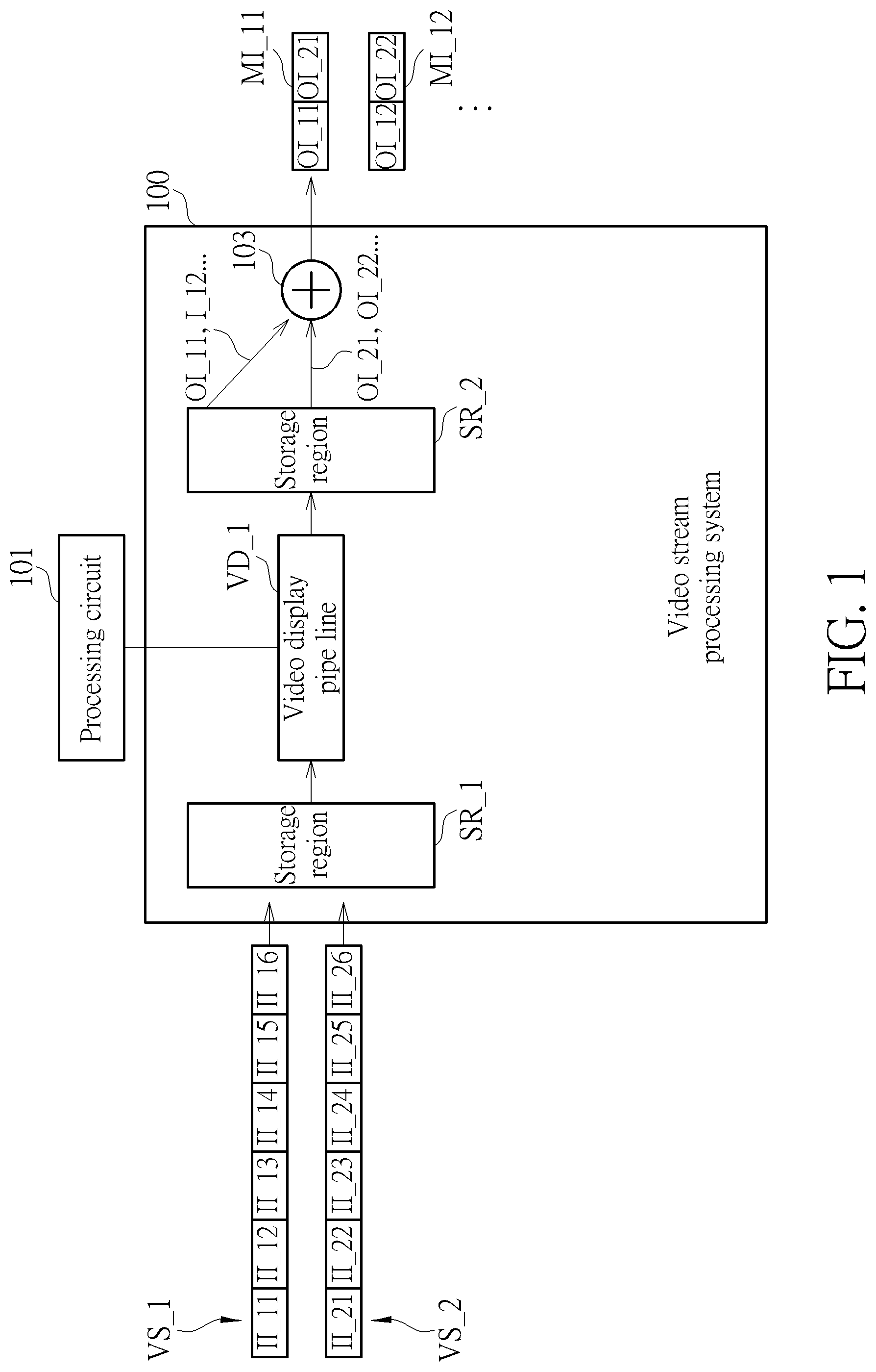
is a schematic diagram illustrating a video stream processing system according to one embodiment of the present application. As shown in , the video stream processing system 100 comprises a first VDP VD_ 1 and an image merging circuit 103 . The first VDP VD_ 1 is configured to process first input images (only first input images II_ 11 , II_ 12 , II_ 13 , II_ 14 , II_ 15 and II_ 16 are shown for examples) of a first video stream VS_ 1 to generate first output images (only first output images OI_ 11 , OI_ 12 are shown for examples), and configured to process second input images (only second input images II_ 21 , II_ 22 , II_ 23 , II_ 24 , II_ 25 and II_ 26 are shown for examples) of a second video stream VS_ 2 to generate second output images (only second output images OI_ 21 , OI_ 22 are shown for examples). The first VDP VD_ 1 can perform various processes to the first input images II_ 11 . . . II_ 16 and the second input images II_ 21 . . . II_ 26 . For example, the first VDP VD_ 1 may perform gradation smoothing, noise reduction, motion compensation, clarity enhancement, contrast enhancement, or color enhancement, but not limited. The first video stream VS_ 1 and the second video stream VS_ 2 may come from any video source, for example, a memory or a website.
The image merging circuit 103 is configured to merge one of the first output images and one of the second output images, to generate a first merged image. For example, the image merging circuit 103 merges the first output image OI_ 11 and the second output image OI_ 21 to generate a first merged image MI_ 11 . Similarly, the image merging circuit 103 merges the first output image OI_ 12 and the second output image OI_ 22 to generate a first merged image MI_ 12 . In other words, the image merging circuit 103 generates a merged video stream corresponding to the first video stream VS_ 1 and the second video stream VS_ 2 . In one embodiment, the first output images OI_ 11 , OI_ 12 and the second output images OI_ 21 , OI_ 22 which are input to the image merging circuit 103 have the same resolutions. In another embodiment, the first output images OI_ 11 , OI_ 12 and the second output images OI_ 21 , OI_ 22 which are input to the image merging circuit 103 have different resolutions.
In the embodiment of , the video stream processing system 100 further comprises a first storage region SR_ 1 and a second storage region SR_ 2 . The first storage region SR_ 1 is coupled to an input of the first VDP VD_ 1 , configured to buffer the first input images II_ 11 . . . II_ 16 and the second input images II_ 21 . . . II_ 26 . The second storage region SR_ 2 is coupled to an output of the first VDP VD_ 1 and an input of the image merging circuit 103 , configured to buffer the first output images OI_ 11 , OI_ 12 and the second output images OI_ 21 , OI_ 22 . In one embodiment, the first storage region SR_ 1 and the second storage region SR_ 2 are different regions of a single storage device (e.g., a DRAM). In another embodiment, the first storage region SR_ 1 and the second storage region SR_ 2 are different storage devices. Please note, the input image illustrated in each of the embodiments may be a partial region of a video frame or a whole video frame, depending on the processing strategy and hardware performance.
In one embodiment, the first video stream VS_ 1 and the second video stream VS_ 2 have identical frame rates. In such case, the first output images OI_ 11 , OI_ 12 and the second output images OI_ 21 , OI_ 22 are sequentially generated by the first VDP VD_ 1 and then merged to generate the first merged images MI_ 11 . MI_ 12 . . . . In another embodiment, the first video stream VS_ 1 and the second video stream VS_ 2 have different frame rates. For example, when the first video stream VS_ 1 has a higher frame rate of 120 FPS (frames per second) and the second video stream VS_ 2 has a lower frame rate of 60 fps, the frame of the second video stream VS_ 2 is updated once every two frames of the first video stream VS_ 1 . Accordingly, the first VDP VD_ 1 has to process 180 frames in one second. In some embodiments, the first VDP VD_ 1 does not necessarily follow the chronological order of the video streams to process the input images. In other words, the first VDP VD_ 1 independently process the input images, and does not necessarily process the second input images once every two first input images based on the frame rates of the video streams. After the input images of the two video streams are processed, output images are obtained, and are output to the image merging circuit 103 to generate merged images based on a frame rate being displayed.
In the embodiment of , the first VDP VD_ 1 is coupled to a processing circuit 101 , which is configured to control the first VDP VD_ 1 . In one embodiment, the processing circuit 101 may further comprises other control functions. For example, if the video stream processing system 100 is provided in a television, the processing circuit 101 can be a processor in the television and can control the operations of the television. For another example, if the video stream processing system 100 is provided in a mobile phone, the processing circuit 101 can be a processor in the mobile phone and can control the operations of the mobile phone. However, the processing circuit 101 can be a circuit specifically designed for the first VDP VD_ 1 .
is a control mechanism of the video stream processing systems illustrated in , according to one embodiment of the present application. In such embodiment, each time the first VDP VD_ 1 processes an image, the first VDP VD_ 1 receives configuration settings from the processing circuit 101 before processing the image, and then processes the image based on the configuration settings. Specifically, as shown in , before processing the first image II_ 11 , the processing circuit 101 transmits configuration settings CS_a (e.g., con A) to the first VDP VD_ 1 and triggers the first VDP VD_ 1 to process the first image II_ 11 . Then, the first VDP VD_ 1 processes the first image II_ 11 according to the configuration settings CS_a.
After the processing of the first image II_ 11 is completed, the first VDP VD_ 1 sends an interrupt IRQ to the processing circuit 101 to inform the processing circuit 101 that the processing of the first image II_ 11 is completed. The processing circuit 101 starts to generate the configuration settings while receiving the interrupt IRQ. Similarly, before processing the second image II_ 21 , the processing circuit 101 transmits configuration settings CS_b to the first VDP VD_ 1 and triggers the first VDP VD_ 1 to process the second image II_ 21 . Then, the first VDP VD_ 1 processes the second image II_ 21 according to the configuration settings (e.g., con B). The first VDP VD_ 1 may process other first images and second images following the same way, as shown in .
The configuration settings in may vary corresponding to the components contained in the first VDP VD_ 1 . In one embodiment, the configuration settings comprises at least one kind of following parameters: a storage region address to be read by the first VDP (e.g., an address of the first storage region SR_ 1 ), a storage region address to be written by the first VDP (e.g., an address of the second storage region SR_ 2 ), and image quality improvement parameters (if the first VDP VD_ 1 comprises a function of image quality improvement).
In the embodiment of , the first VDP VD_ 1 receives configuration settings for one image each time. However, in another embodiment, the first VDP VD_ 1 receives configuration settings for a group of images one time rather than for only one image. is a schematic diagram illustrating a video stream processing system according to another embodiment of the present application. is a control mechanism of the video stream processing systems illustrated in , according to one embodiment of the present application. In the embodiment of , the processing circuit 101 is coupled to a third storage region SR_ 3 . In one embodiment, the first storage region SR_ 1 , the second storage region SR_ 2 and the third storage region SR_ 3 are different regions of a single storage device (e.g., a DRAM). In another embodiment, the first storage region SR_ 1 , the second storage region SR_ 2 and the third storage region SR_ 3 are different storage devices.
The third storage region SR_ 3 is configured to buffer a first group of configuration settings for a first group of images from the processing circuit 101 . The first VDP VD_ 1 reads the first group of configuration settings from the third storage region SR_ 3 before processing the first group of images, and processes the first group of images according to the first group of configuration settings. For example, in the embodiment of , the first VDP VD_ 1 reads the first group of configuration settings CS_ 1 (e.g., Con A, Con B) from the third storage region SR_ 3 before processing the first group of images GI_ 1 (e.g., the first images II_ 11 , II_ 12 and the second images II_ 21 , II_ 22 ). Next, the first VDP VD_ 1 processes images in the first group of images GI_ 1 sequentially according to the first group of configuration settings CS_ 1 . In one embodiment, the processing circuit 101 sets the storage address of the first group of configuration settings CS_ 1 to the first VDP VD_ 1 . Then, the first VDP VD_ 1 sequentially reads required configuration settings from the third storage region SR_ 3 (e.g., II_ 11 's CS_a, II_ 21 's CS_b, II_ 12 's CS_a, II_ 22 's CS_b).
Afterwards, the first VDP VD_ 1 sends an interrupt IRQ to trigger the processing circuit 101 to generate a second group of configuration settings CS_ 2 while processing the first group of images GI_ 1 , and then the processing circuit 101 correspondingly transmits the second group of configuration settings CS_ 2 to the third storage region SR_ 3 . In one embodiment, the first VDP VD_ 1 sends the interrupt IRQ in response to an execution status of the first group of images GI_ 1 . In another embodiment, the first VDP VD_ 1 sends the interrupt IRQ while completing the processing of the first group of images GI_ 1 . Next, the first VDP reads the second group of configuration settings CS_ 2 from the third storage region SR_ 3 before processing a second group of images GI_ 2 , and processes images in the second group of images GI_ 2 sequentially, according to the second group of configuration settings CS_ 2 .
It will be appreciated that the first group of images GI_ 1 and the second group of images GI_ 2 are not limited to have identical image arrangements. For more detail, the first group of images GI_ 1 comprises a plurality of pairs of images. Each of the pairs of images comprises a first image and a second image. For example, the first group of images GI_ 1 comprises two pairs of images. One pair of images comprises the first image II_ 11 and the second image II_ 21 , and the other pair of images comprises the first image II_ 12 and the second image II_ 22 . However, the second group of images GI_ 2 is not limited to comprise such pair of images. In some embodiments, the images from the video streams are not uniformly distributed in the groups of images. For example, the first group of images GI_ 1 may comprise three first input images II_ 11 , II_ 12 and II_ 13 and one second input image II_ 21 and the second group of images GI_ 2 may comprise one first input image II_ 14 and three second input images II_ 22 , II_ 23 and II_ 24 and the third group of images GI 3 may comprise two first input images II_ 15 and II_ 16 . Additionally, the group of configuration settings CS_ 1 , CS_ 2 in may vary corresponding to the components contained in the first VDP VD_ 1 . In one embodiment, the group of configuration settings comprises at least one kind of following parameters: a storage region address to be read by the first VDP (e.g., an address of the first storage region SR_ 1 ), a storage region address to be written by the first VDP (e.g., an address of the second storage region SR_ 2 ), and image quality improvement parameters (if the first VDP VD_ 1 comprises a function of image quality improvement).
In the above-mentioned embodiments, the video stream processing system 100 comprises only one VDP, which can process more than one video streams. However, the video stream processing system 100 may comprise more than one VDP, which can respectively process more than one video streams. is a schematic diagram illustrating a video stream processing system according to another embodiment of the present application. As shown in , the video stream processing system 100 further comprises a second VDP VD_ 2 . The second VDP VD_ 2 is configured to process third input images II_ 31 . . . II_ 36 in a third video stream VS_ 3 to generate third output images OI_ 31 , OI_ 32 , and configured to process fourth input images II_ 41 . . . II_ 46 in a fourth video stream VS_ 4 to generate fourth output images OI_ 41 , OI_ 42 . After that, the image merging circuit 103 is configured to merge one of the third output images II_ 31 . . . II_ 36 and one of the fourth output images II_ 41 . . . II_ 46 , to generate a second merged image. For example, the image merging circuit 103 merges the third output image II_ 31 and the fourth output image II_ 41 to generate the second merged image MI 21 .
One of the first VDP VD_ 1 and the second VDP VD_ 2 may be selected to generate the merged image. If the first VDP VD_ 1 is selected, first merged images corresponding first input images thereof are generated. That is, a first multi-video stream corresponding to the first video steam VS_ 1 and the second video steam VS_ 2 is generated. If the second VDP VD_ 2 is selected, second merged images corresponding second input images thereof are generated. That is, a second multi-video stream corresponding to the third video steam VS_ 3 and the fourth video steam VS_ 4 is generated. The number of the VDP can be reduced in view of above-mentioned embodiments. Accordingly, the first VDP VD_ 1 and the second VDP VD_ 2 can both have high qualities. By this way, the user experience can still be good even if the video stream processing system 100 switches between the first VDP VD_ 1 and the second VDP VD_ 2 .
The multi-video stream generated by the image merging circuit 103 can correspond to more than one VDPs rather than only one VDP. Accordingly, as shown in , a third merged image MI 31 which comprises the first output image OI_ 11 , the second output image OI_ 21 , the third output image OI_ 31 and the fourth output image OI_ 41 can be generated if both of the first VDP VD_ 1 and the second VDP VD_ 2 are selected.
In above-mentioned embodiments, two video streams are processed by a single VDP. However, a single VDP can process more than two video streams. As shown in the embodiment of , the first storage region SR_ 1 further receives the video streams VS_a, VS_b. In such case, the first storage region SR_ 1 buffers the first input images II_ 11 . . . II_ 16 of the first video stream VS_ 1 , the second input images II_ 21 . . . II_ 26 of the second video stream VS_ 2 , the input images II_a 1 . . . II_a 6 of the video stream VS_a and input images II_b 1 . . . II_b 6 of the video stream VS_b. The first VDP VD_ 1 processes the first input images II_ 11 . . . II_ 16 to generate first output images OI_ 11 , OI_ 12 . . . , processes the second input images II_ 21 . . . II_ 26 to generate second output images OI_ 21 , OI_ 22 . . . , processes the input images II_a 1 . . . II_a 6 to generate output images OI_a 1 , OI_a 2 . . . , and processes the input images II_b 1 . . . II_b 6 to generate output images OI_b 1 , OI_b 2 . . . . Also, the second storage region SR_ 2 buffers the first output images OI_ 11 , OI_ 12 , the second output images OI_ 21 , OI_ 22 , the output images OI_a 1 , OI_a 2 . . . and the output images OI_b 1 , OI_b 2 . . . .
The image merging circuit 103 merges one of the first output images OI_ 11 , OI_ 12 . . . , one of the second output images OI_ 21 , OI_ 22 , one of the output images OI_a 1 , OI_a 2 . . . and one of the output images OI_b 1 , OI_b 2 to generate a first merged image. For example, the image merging circuit 103 merges the first output image OI_ 11 , the second output image OI_ 21 , the output image OI_a 1 and the output image OI_b 1 to generate a first merged image MI_ 11 . For another example, the image merging circuit 103 merges the first output image OI_ 12 , the second output image OI_ 22 , the output image OI_a 2 and the output image OI_b 2 to generate a first merged image MI_ 12 . In other words, a merged multi-video stream corresponding to the first video stream VS_ 1 , the second video stream VS_ 2 , the video stream VS_a and the video stream VS_b is generated.
In one embodiment, the first output images OI_ 11 , OI_ 12 , the second output images OI_ 21 , OI_ 22 , the output images OI_a 1 , OI_a 2 , OI_b 1 , OI_b 2 which are input to the image merging circuit 103 have the same resolutions. In another embodiment, the first output images OI_ 11 , OI_ 12 , the second output images OI_ 21 , OI_ 22 , the output images OI_a 1 , OI_a 2 , OI_b 1 , OI_b 2 which are input to the image merging circuit 103 have different resolutions.
is a scenario diagram illustrating a multi-video display which uses the video stream processing system in above-mentioned embodiments. In the embodiment of , the video streams VS_P, VS_Q, VS_X, VS_Y are television programs and the multi-video displays MD_ 1 , MD_ 2 , MD_ 3 are televisions. In one embodiment, the multi-video display MD_ 1 corresponds the embodiment of . That is, the multi-video display MD_ 1 displays a merged video stream corresponding to the video streams VS_P, VS_Q.
In one embodiment, the multi-video displays MD_ 1 , MD_ 2 , MD_ 3 correspond to the embodiment of . That is, the first VDP VD_ 1 or the second VDP VD_ 2 can be selected, such that a merged video stream corresponding to the video streams VS_P, VS_Q can be displayed as shown on the multi-video displays MD_ 1 or a merged video stream corresponding to the video streams VS_X, VS_Y can be displayed as shown on the multi-video displays MD_ 2 or a merged video stream corresponding to the video streams VS_P, VS_Q, VS_X, VS_Y can be displayed as shown on the multi-video displays MD_ 3 . Please note in such embodiment, the multi-video display MD_ 1 , MD_ 2 and MD_ 3 scenarios are the same multi-video display. In one embodiment, the multi-video display MD_ 3 corresponds the embodiment of . That is, the multi-video display MD_ 3 displays a merged video stream corresponding to the video streams VS_P, VS_Q, VS_X and VS_Y. However, the number of video streams to be merged can be adjusted upon the need and the merged video stream can be displayed in other forms (e.g., each video can output different resolution or can overlap each other) rather than the rectangles or squares shown in .
In view of above-mentioned embodiments, a video stream processing method can be acquired. is a flow chart illustrating a video stream processing method according to one embodiment of the present application. The video stream processing method comprises:
Step 801
Process first input images (e.g., II_ 11 . . . II_ 16 ) of a first video stream (e.g., VS_ 1 ) to generate first output images (e.g., OI_ 11 , OI_ 12 ) by a first VDP (e.g., VD_ 1 ).
Step 803
Process second input images (e.g., II_ 21 . . . II_ 26 ) of a second video stream (e.g., VS_ 2 ) to generate second output images (e.g., OI_ 21 , OI_ 22 ) by the first VDP
Step 805
Merge one of the first output images and one of the second output images, to generate a first merged image (e.g., MI_ 11 or MI_ 12 ).
Other detail steps can be acquired in view of above-mentioned embodiments, thus are omitted for brevity here.
In view of above-mentioned embodiments, the number of VDPs can be decreased since a single VDP can process more than one video streams. Also, the transition between VDPs with different image qualities can be avoided.
Those skilled in the art will readily observe that numerous modifications and alterations of the device and method may be made while retaining the teachings of the invention. Accordingly, the above disclosure should be construed as limited only by the metes and bounds of the appended claims.
Figures (8)
Citations
This patent cites (6)
- US8121349
- US2005/0251847
- US2011/0316863
- US2013/0055320
- US2017/0339431
- US201021548