Filtering Method, Filtering Device, and Storage Medium Stored with Filtering Program
Abstract
A filtering method includes: receiving a first audio signal and a second audio signal that include sound emitted from a same sound source at different volumes; generating a filter signal by convoluting adaptive filter coefficients into the second audio signal; removing components of the filter signal from the first audio signal; and limiting a gain of the adaptive filter coefficients to 1.0 or less.
Claims (11)
1. A filtering method comprising: receiving a first audio signal and a second audio signal, wherein: the first audio signal represents first sound emitted from a first sound source and second sound emitted from a second sound source, a volume of the first sound from the first sound source being greater than a volume of the second sound from the second sound source in the first audio signal; and the second audio signal represents the first sound emitted from the first sound source and the second sound emitted from the second source, the volume of the second sound from the second sound source being greater than the volume of the first sound from the first sound source in the second audio signal; transforming the first audio signal to a first transformed audio signal with respect to frequency and the second audio signal to a second transformed audio signal with respect to frequency; calculating first filter coefficients with respect to frequency of a first FIR filter that minimize a level of a first reference signal based on the first and second transformed audio signals, the first FIR filter functioning as a first adaptive filter; calculating second filter coefficients with respect to frequency of a second FIR filter that minimize a level of a second reference signal based on the first and second transformed audio signals, the second FIR filter functioning as a second adaptive filter; limiting gains of the calculated first filter coefficients of the first FIR filter for each frequency component to 1.0 or less, in a state where the gains thereof exceed 1.0; limiting gains of the calculated second filter coefficients of the second FIR filter for each frequency component to 1.0 or less, in a state where the gains thereof exceed 1.0; generating a first filter signal by convoluting the calculated first filter coefficients of the first FIR filter into the second audio signal; generating a second filter signal by convoluting the calculated second filter coefficients of the second FIR filter into the first audio signal; generating the first reference signal by removing components of the first filter signal from the first audio signal; generating the second reference signal by removing components of the second filter signal from the second audio signal, wherein the first filter coefficients are expressed by complex numbers by which each frequency component of the second audio signal is to be multiplied respectively in the first FIR filter, wherein the second filter coefficients are expressed by complex numbers by which each frequency component of the first audio signal is to be multiplied respectively in the second FIR filter, wherein the calculating of the first filter coefficients of the first FIR filter updates the first filter coefficients of the first FIR filter in a state where a volume ratio of the second audio signal to the first audio signal exceeds a first predetermined threshold, and wherein the calculating of the second filter coefficients of the second FIR filter updates the second filter coefficients of the second FIR filter in a state where a volume ratio of the first audio signal to the second audio signal exceeds a second predetermined threshold.
6. A filtering device comprising: a processor configured to: receive a first audio signal and a second audio signal, wherein: the first audio signal represents first sound emitted from a first sound source and second sound emitted from a second sound source, a volume of the first sound from the first sound source being greater than a volume of the second sound from the second sound source in the first audio signal; and the second audio signal represents the first sound emitted from the first sound source and the second sound emitted from the second source, the volume of the second sound from the second sound source being greater than the volume of the first sound from the first sound source in the second audio signal; transform the first audio signal to a first transformed audio signal with respect to frequency and the second audio signal to a second transformed audio signal with respect to frequency; calculate first filter coefficients with respect to frequency of a first FIR filter that minimize a level of a first reference signal based on the first and second transformed audio signals, the first FIR filter functioning as a first adaptive filter; calculate second filter coefficients with respect to frequency of a second FIR filter that minimize a level of a second reference signal based on the first and second transformed audio signals, the second FIR filter functioning as a second adaptive filter; limit gains of the calculated first filter coefficients of the first FIR filter for each frequency component to 1.0 or less, in a state where the gains thereof exceed 1.0; limiting gains of the calculated second filter coefficients of the second FIR filter for each frequency component to 1.0 or less, in a state where the gains thereof exceed 1.0; generate a first filter signal by convoluting the calculated first filter coefficients of the first FIR filter into the second audio signal; generate a second filter signal by convoluting the calculated second filter coefficients of the second FIR filter into the first audio signal; generate the first reference signal by removing components of the first filter signal from the first audio signal; generate the second reference signal by removing components of the second filter signal from the second audio signal, wherein the first filter coefficients are expressed by complex numbers by which each frequency component of the second audio signal is to be multiplied respectively in the first FIR filter, wherein the second filter coefficients are expressed by complex numbers by which each frequency component of the first audio signal is to be multiplied respectively in the second FIR filter, wherein the processor, in calculating the first filter coefficients of the first FIR filter, updates the first filter coefficients of the first FIR filter in a state where a volume ratio of the second audio signal to the first audio signal exceeds a first predetermined threshold, and wherein the processor, in calculating the second filter coefficients of the second FIR filter, updates the second filter coefficients of the second FIR filter in a state where a volume ratio of the first audio signal to the second audio signal exceeds a second predetermined threshold.
11. A non-transitory storage medium storing a program executable by a computer to execute a method comprising: receiving a first audio signal and a second audio signal, wherein: the first audio signal represents first sound emitted from a first sound source and second sound emitted from a second sound source, a volume of the first sound from the first sound source being greater than a volume of the second sound from the second sound source in the first audio signal; and the second audio signal that represents the first sound emitted from the first sound source and the second sound emitted from the second source, the volume of the second sound from the second sound source being greater than the volume of the first sound from the first sound source in the second audio signal; transforming the first audio signal to a first transformed audio signal with respect to frequency and the second audio signal to a second transformed audio signal with respect to frequency; calculating first filter coefficients with respect to frequency of a first FIR filter that minimize a level of a first reference signal based on the first and second transformed audio signals, the first FIR filter functioning as a first adaptive filter; calculating second filter coefficients with respect to frequency of a second FIR filter that minimize a level of a second reference signal based on the first and second transformed audio signals, the second FIR filter functioning as a second adaptive filter; limiting gains of the calculated first filter coefficients of the first FIR filter for each frequency component to 1.0 or less, in a state where the gains thereof exceed 1.0; limiting gains of the calculated second filter coefficients of the second FIR filter for each frequency component to 1.0 or less, in a state where the gains thereof exceed 1.0; generating a first filter signal by convoluting the calculated first filter coefficients of the first FIR filter into the second audio signal; generating a second filter signal by convoluting the calculated second filter coefficients of the second FIR filter into the first audio signal; generating the first reference signal by removing components of the first filter signal from the first audio signal; generating the second reference signal by removing components of the second filter signal from the second audio signal, wherein the first filter coefficients are expressed by complex numbers by which the frequency component of the second audio signal is to be multiplied respectively in the first FIR filter, wherein the second filter coefficients are expressed by complex numbers by which the frequency component of the first audio signal is to be multiplied respectively in the second FIR filter, wherein the calculating of the first filter coefficients of the first FIR filter updates the first filter coefficients of the first FIR filter in a state where a volume ratio of the second audio signal to the first audio signal exceeds a first predetermined threshold, and wherein the calculating of the second filter coefficients of the second FIR filter updates the second filter coefficients of the second FIR filter in a state where a volume ratio of the first audio signal to the second audio signal exceeds a second predetermined threshold.
Show 8 dependent claims
2. The filtering method according to claim 1 , further comprising: performing first voice recognition processing using the first reference signal; and performing second voice recognition processing using the second reference signal.
3. The filtering method according to claim 1 , further comprising: performing first non-linear processing of the first reference signal; and performing second non-linear processing of the second reference signal.
4. The filtering method according to claim 1 , wherein: the second audio signal includes a number N of kinds of second audio signals; the first filter coefficients of the first FIR filter include the same number N of kinds of first filter coefficients; and the first filter signal is generated by convoluting the number N of kinds of the first filter coefficients into the number N of second audio signals.
5. The filtering method according to claim 1 , wherein: the limiting gain of the calculated first filter coefficients limits the gain of each frequency component; and the limiting gain of the calculated second filter coefficients limits the gain of each frequency component.
7. The filtering device according to claim 6 , wherein the processor is further configured to: perform first voice recognition processing using the first reference signal; and perform second voice recognition processing using the second reference signal.
8. The filtering device according to claim 6 , wherein the processor is further configured to perform: first non-linear processing of the first reference signal; and second non-linear processing of the second reference signal.
9. The filtering device according to claim 6 , wherein: the first filter coefficients of the first FIR filter limit the gain of each frequency component, and the second filter coefficients of the second FIR filter limit the gain of each frequency component.
10. The filtering device according to claim 6 , wherein: the second audio signal includes a number N of kinds of second audio signals; the first filter coefficients of the first FIR filter include the same number N of kinds of first filter coefficients; and the first filter signal is generated by convoluting the number N of kinds of the first filter coefficients into the number N of second audio signals.
Full Description
Show full text →
CROSS REFERENCE TO RELATED APPLICATIONS
This Nonprovisional application claims priority under 35 U.S.C. § 119(a) on Patent Application No. 2020-129083 filed in Japan on Jul. 30, 2020, the entire contents of which are hereby incorporated by reference.
BACKGROUND
Technical Field
The present disclosure relates to a filtering method for filtering an audio signal.
Background Information
In the past, there have been suggested sound separation devices that eliminate noise and separate a speaker's voice (target sound) from an audio signal. For example, Japanese Patent Application Publication 2001-100800 discloses a method for eliminating noise by spectral subtraction.
However, when both the target sound and the noise are voices, it is difficult to separate the target sound only by spectral subtraction as disclosed in Japanese Patent Application Publication No. 2001-100800.
International Patent Application Publication No. WO2007-18293A1 discloses a sound separation device that can separate target sound even when both the target sound and the noise are voices. The sound separation device disclosed in International Patent Application Publication No. WO2007-18293A1 calculates the respective power spectrums of a plurality of audio source signals and calculates the power spectrum difference. The sound separation device adjusts the level of each frequency component of each of the audio source signals with a gain based on the calculated power spectrum difference.
SUMMARY
In the method disclosed in International Patent Application Publication No. WO2007-18293A1, non-linear processing, in which different frequency components of each audio source signal are multiplied by different gains, is performed. This method disclosed in International Patent Application Publication No. WO2007-18293A1 may cause a great distortion of the spectrum and may result in severe deterioration of the audio quality. In addition, the method disclosed in International Patent Application Publication No. WO2007-18293A1 deteriorates the accuracy of signal processing based on the envelope (for example, voice recognition processing).
An object of an embodiment of the present disclosure is to provide a filtering method that can separate target sound without causing a distortion of the spectrum.
A filtering method according to an embodiment of the present disclosure includes: receiving a first audio signal and a second audio signal that include sound emitted from a same sound source at different volumes generating a filter signal by convoluting adaptive filter coefficients into the second audio signal removing components of the filter signal from the first audio signal; and limiting a gain of the adaptive filter coefficients to 1.0 or less.
The embodiment of the present disclosure makes it possible to separate target sound without causing a distortion of the spectrum.
BRIEF DESCRIPTION OF THE DRAWINGS
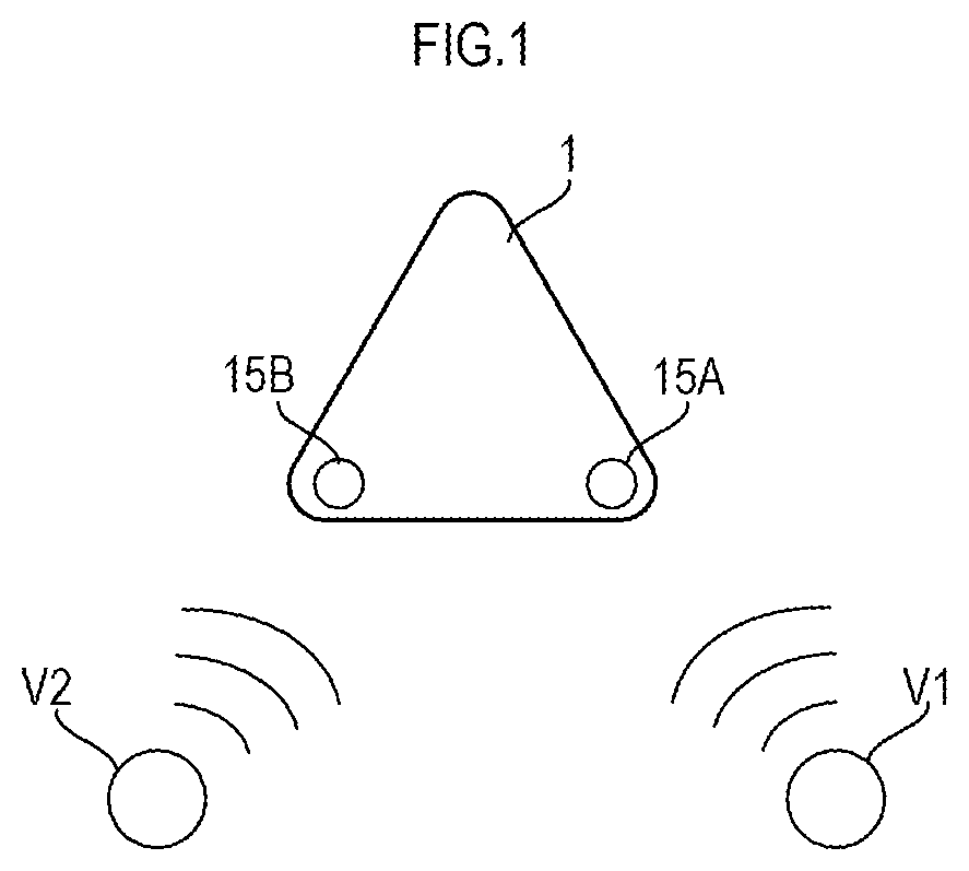
is a schematic external view of a sound pickup device 1 .
is a block diagram showing the configuration of the sound pickup device 1 .
is a block diagram showing the functional configuration of a processor 12 .
is a flowchart showing a filtering procedure.
is a block diagram showing the functional configuration of the processor 12 when the processor 12 additionally performs voice recognition processing.
is a block diagram of the functional configuration of the processor 12 when the processor 12 additionally performs non-linear processing.
is a schematic external view of a sound pickup device 1 A according to a modification.
is a block diagram showing the functional configuration of the processor 12 when an audio signal S 3 is additionally received.
DETAILED DESCRIPTION
is a schematic external view of a sound pickup device 1 . The sound pickup device 1 includes a microphone 15 A and a microphone 15 B. The microphones 15 A and 15 B individually pick up the surrounding sounds. In the example shown in , the microphone 15 A and the microphone 15 B are to pick up the voice of a speaker V 1 and the voice of another speaker V 2 , respectively.
is a block diagram showing the configuration of the sound pickup device 1 . The sound pickup device 1 includes a communicator 11 , a processor 12 , a RAM 13 , a flash memory 14 , a microphone 15 A, and a microphone 15 B.
The sound pickup device 1 is an example of a filtering device according to the present disclosure. The sound pickup device 1 filters the audio signals caught by the microphones 15 A and 15 B. In , the audio signal caught by the microphone 15 A includes the voice of the speaker V 1 and the voice of the speaker V 2 . Similarly, the audio signal caught by the microphone 15 B includes the voice of the speaker V 1 and the voice of the speaker V 2 .
The microphone 15 A is placed near the speaker V 1 , and the microphone 15 B is placed near the speaker V 2 . Accordingly, the microphone 15 A picks up a greater volume (a higher level) of the voice of the speaker V 1 than the voice of the speaker V 2 . The microphone 15 B picks up a higher level of the voice of the speaker V 2 than the level of the voice of the speaker V 1 . Thus, the audio signal caught by the microphone 15 A and the audio signal caught by the microphone 15 B include sounds from the same sound sources, but the volumes of the sounds included in the respective audio signals are different.
The sound pickup device 1 filters the audio signal caught by the microphone 15 A to remove the components of the voice of the speaker V 2 , which are on low levels, from the audio signal. In addition, the sound pickup device 1 filters the audio signal caught by the microphone 15 B to remove the components of the voice of the speaker V 1 , which are on low levels, from the audio signal.
The sound pickup device 1 sends the filtered audio signal to another device, for example, via the communicator 11 . The sound pickup device 1 may further include a speaker. In this case, the speaker emits sound in accordance with an audio signal that the speaker received from another device via the communicator 11 . In this case, for example, the sound pickup device 1 works as a telecommunication device that is connected to other devices located in distant places to send and receive audio data to and from the devices in distant places.
The processor 12 can perform various kinds of processing by reading programs from a flash memory 14 (a storage medium) and storing the programs temporarily on the RAM 13 . Such programs include a filtering program 141 . The flash memory 14 additionally stores operation programs, such as firmware, etc., for operating the processor 12 . The programs to be read by the processor 12 are not necessarily stored in the flash memory 14 in the sound pickup device 1 itself. For example, the programs may be stored in a storage medium in an external device such as a server or the like. In this case, the processor 12 reads a program from the server and stores the program on the RAM 13 to perform the processing when necessary.
The microphone 15 A catches a first audio signal S 1 , and the microphone 15 B catches a second audio signal S 2 . The microphones 15 A and 15 B convert the audio signals into digital signals and output the digital signals to the processor 12 .
The processor 12 filters the audio signal S 1 caught by the microphone 15 A and the audio signal S 2 caught by the microphone 15 B. is a block diagram showing the functional configuration of the processor 12 . is a flowchart showing a procedure for the filtering.
The processor 12 functionally includes a filter bank analyzer 121 A, another filter bank analyzer 121 B, a filter coefficient calculator 122 , a filter coefficient limiter 123 , a FIR (finite impulse response) filter 124 , an adder 125 , and a filter bank synthesizer 126 . These functions are implemented by the filtering program 141 .
First, the processor 12 receives the audio signal S 1 caught by the microphone 15 A and the audio signal S 2 caught by the microphone 15 B (S 11 ). Thus, the processor 12 functions as a receiver. As described above, each of the audio signal S 1 caught by the microphone 15 A and the audio signal caught by the microphone 15 B includes the voice of the speaker V 1 and the voice of the speaker V 2 .
The filter bank analyzer 121 A transforms the audio signal S 1 caught by the microphone 15 A into an audio signal F 1 with respect to frequency and extracts various frequency components separately (S 12 ). Similarly, the filter bank analyzer 121 B transforms the audio signal S 2 caught by the microphone 15 B into an audio signal F 2 with respect to frequency and extracts various frequency components separately (S 12 ).
The filter coefficient calculator 122 calculates filter coefficients C 2 to be used in the FIR filter 124 (S 13 ). The filter coefficients C 2 are coefficients expressed by complex numbers by which the frequency components of the audio signal F 2 are to be multiplied respectively in the FIR filter 124 .
The filter coefficient limiter 123 limits the gains to be achieved by the filter coefficients C 2 calculated by the filter coefficient calculator 122 to 1.0 or less (S 14 ), thereby calculating corrected filter coefficients CT. In this way, the filter coefficient limiter 123 prevents the frequency components of the audio signal F 2 from being amplified.
The FIR filter 124 convolutes the corrected filter coefficient C 2 ′ into the audio signal F 2 , thereby generating a filter signal FT (S 15 ). The filter coefficients C 2 are updated by the filter coefficient calculator 122 , and accordingly, the corrected filter coefficients CT are updated. Thus, the FIR filter 124 functions as an adaptive filter.
The adder 125 subtracts the filter signal F 2 ′ from the audio signal F 1 , thereby removing the components of the filter signal F 2 ′ from the audio signal F 1 (S 16 ). The adder 125 outputs an audio signal F 1 ′ obtained by the subtraction. The adder 125 corresponds to an eliminator of the present disclosure.
The filter bank synthesizer 126 transforms the audio signal F 1 ′ into an audio signal S 1 ′ with respect to time (S 17 ).
The filter coefficient calculator 122 receives the audio signal F 2 and the audio signal F 1 . The filter coefficient calculator 122 updates the filter coefficients by using a specified algorithm, such as LMS (least mean squares) or the like. The filter coefficient calculator 122 generates an update filter signal by convoluting the filter coefficients C 2 into the audio signal F 2 . The filter coefficient calculator 122 subtracts the update filter signal from the audio signal F 1 . The resultant signal is referred to as a reference signal. The filter coefficient calculator 122 updates the filter coefficients C 2 to values that minimize the level of the reference signal. As the time passes, the calculated filter coefficients C 2 are updated so that the update filter signal can remove the voice of the speaker V 2 from the audio signal F 1 . Accordingly, the corrected filter coefficients C 2 ′ used in the FIR filter 124 are updated so that the filter signal F 2 ′ can remove the voice of the speaker V 2 from the audio signal F 1 .
Both the audio signal F 1 and the audio signal F 2 include the voice of the speaker V 1 . The filter coefficient calculator 122 calculates filter coefficients C 2 that minimize the level of the reference signal, and therefore, the filter coefficients C 2 are updated to values that remove not only the voice of the speaker V 2 but also the voice of the speaker V 1 from the audio signal F 1 . However, the level of the voice of the speaker V 1 in the audio signal F 1 is higher than the level of the voice of the speaker V 2 in the audio signal F 1 . Therefore, the filter coefficient calculator 122 calculates coefficients having gains of 1.0 or more, which will reduce the voice of the speaker V 1 in the audio signal F 1 .
On the other hand, the filter coefficient limiter 123 limits the gains to be achieved by the filter coefficients to 1.0 or less. Accordingly, the level of the voice of the speaker V 1 in the filter signal F 2 ′ is lower than the level of the voice of the speaker V 1 in the audio signal F 1 . Therefore, the voice of the speaker V 1 in the audio signal F 1 is not completely removed by the filter signal F 2 ′ and remains in the audio signal F 1 ′.
In this way, the processor 12 removes the voice of the speaker V 2 as noise components and separates the voice of the speaker V 1 as the target sound.
In order to remove the voice of the speaker V 2 and not remove the voice of the speaker V 1 from the audio signal F 1 , it is preferred that the filter coefficient calculator 122 updates the filter coefficients only when the level of the voice of the speaker V 2 in the audio signal F 2 is high. In other words, when the level of the voice of the speaker V 2 in the audio signal F 2 is low, it is preferred that the filter coefficients are not updated. Therefore, the filter coefficient calculator 122 may update the filter coefficients C 2 for only the frequency components in which the volume ratio of the audio signal F 2 to the audio signal F 1 (F 2 /F 1 ) excesses a predetermined threshold.
The threshold may be any value. For example, when the threshold is 1.0, the filter coefficient calculator 122 updates the filter coefficients C 2 for only the frequency components in which the level of the audio signal F 2 is higher than the level of the audio signal F 1 . Accordingly, in the case where the threshold is 1.0, only when the sound viewed as a noise component is picked up by the microphone 15 B at a higher level than the level of the sound picked up by the microphone 15 A, the processor 12 calculates a filter coefficient that removes the sound. In the case where the threshold is greater than 1.0 (for example, about 1.5), only when the sound viewed as a noise component to be removed is at a still higher level, the processor 12 updates the filter coefficient. With this arrangement, updates of the filter coefficients are performed based on the audio signal F 1 and the voice of the speaker V 2 , and the updates are unlikely to be affected by external noise. This heightens the accuracy of the filter coefficients and enhances the filtering effect. Thus, by setting the threshold to an arbitrary value greater than 1.0 depending on how much the voice of the speaker V 2 , which should be removed, is mixed in the audio signal, the effect of removing the sound viewed as noise components can be set arbitrarily.
The audio signal S 2 picked up by the microphone 15 B is subjected to the same processing. The processor 12 subtracts a filter signal generated from the audio signal S 1 from the audio signal F 2 obtained by frequency transformation of the audio signal S 2 . Thereby, the voice of the speaker V 1 is removed, and the voice of the speaker V 2 is separated as the target sound.
In this way, even when the speakers V 1 and V 2 speak at the same time, the sound pickup device 1 with the above-described structure can separate the picked-up sound into the voice of the speaker V 1 and the voice of the speaker V 2 .
The sound pickup device 1 according to the present embodiment separates target sound from an audio signal by performing linear processing, specifically subtracting a filter signal outputted from an adaptive filter from the audio signal. Therefore, the sound pickup device 1 can separate target sound without distorting the spectrum of the audio signal.
The envelope of a spectrum relates to the characteristics of a person's vocal tract and is significantly important for voice recognition processing. Therefore, the separation of target sound according to the present embodiment is suited to be used for voice recognition processing.
is a block diagram showing the functional configuration of the processor 12 when the processor 12 additionally performs voice recognition processing. The processor 12 shown in further includes a voice recognizer 127 . There are no other differences between the functional configuration of the processor 12 shown in and the functional configuration shown by the block diagram in .
The voice recognizer 127 performs voice recognition based on an output signal from the adder 125 . In other words, the voice recognizer 127 performs voice recognition by using the audio signal F 1 ′ into which the voice of the speaker V 1 is extracted. As described above, the sound pickup device 1 according to the present embodiment separates the voice of the speaker V 1 by linear processing, and this processing does not cause a distortion of the envelope of the spectrum. Therefore, the accuracy of voice recognition performed by the voice recognizer 127 is improved.
However, in a case in which the filtered audio signal is sent to another device in a distant place so that a listener in the distant place can listen to the sound, the processor 12 may perform non-linear processing.
is a block diagram showing the functional configuration of the processor 12 when the processor 12 performs non-linear processing. The processor 12 shown in further includes a non-linear processor 128 . There are no other differences between the functional configuration of the processor 12 shown in and the functional configuration shown by the block diagram in .
The non-linear processor 128 performs non-linear processing of the output signal from the adder 125 . The non-linear processing may be any kind of processing. The non-linear processing is processing to remove the frequency components of a filter signal F 2 ′ from the audio signal F 1 ′ by spectrum subtraction or Wiener filtering. Alternatively, the non-linear processing may be processing to remove echo components from the audio signal F 1 ′ by spectrum subtraction or Wiener filtering. Alternatively, the non-linear processing may be processing to remove steady noise components from the audio signal F 1 ′ by spectrum subtraction or Wiener filtering. In this way, the non-linear processor 128 performs processing, for example, to emphasize the voice of the speaker V 1 .
is a schematic external view of a sound pickup device 1 A according to a modification. The sound pickup device 1 A further includes another microphone 15 C. The sound pickup device 1 A has no other differences in structure from the sound pickup device 1 . In the example shown in , the microphone 15 A, the microphone 15 B and the microphone 15 C are to pick up the voice of the speaker V 1 , the voice of the speaker V 2 and the voice of another speaker V 3 , respectively. The microphone 15 C catches an audio signal S 3 . The audio signal S 3 caught by the microphone 15 C includes the voice of the speaker V 1 , the voice of the speaker V 2 and the voice of the speaker V 3 . However, the audio signal S 3 includes the voice of the speaker V 3 at a higher level than the voice of the speaker V 1 and the voice of the speaker V 2 .
is a block diagram showing the functional configuration of the processor 12 when the processor 12 additionally receives the audio signal S 3 . The processor 12 further includes another filter bank analyzer 121 C. The filter bank analyzer 121 C transforms the audio signal S 3 into an audio signal F 3 with respect to frequency and extracts frequency components separately.
The filter coefficient calculator 122 calculates filter coefficients to be used in the FIR filter 124 , based on the audio signals F 2 and F 3 . In this example, the filter coefficient calculator 122 calculates filter coefficients C 2 and filter coefficients C 3 . The filter coefficient limiter 123 limits the gains to be achieved by the filter coefficients C 2 and the filter coefficients C 3 to 1.0 or less (S 14 ), thereby calculating corrected filter coefficients C 2 ′ and corrected filter coefficients C 3 ′. The FIR filter 124 convolutes the corrected filter coefficients C 2 ′ and the corrected filter coefficients C 3 ′ into the audio signal F 2 and the audio signal F 3 , respectively, thereby generating a filter signal F′. More specifically, the filter signal F′ is the sum of the result of the convolution of the corrected filter coefficients C 2 ′ into the audio signal F 2 and the result of the convolution of the corrected filter coefficients C 3 ′ into the audio signal F 3 (F 2 *C 2 ′+F 3 ′*C 3 ′).
The level of the voice of the speaker V 1 in the audio signal S 2 is lower than the level of the voice of the speaker V 1 in the audio signal S 1 . Similarly, the level of the voice of the speaker V 1 in the audio signal S 3 is lower than the level of the voice of the speaker V 1 in the audio signal S 1 . Therefore, the filter coefficient calculator 122 calculates filter coefficients C 2 and C 3 having gains of 1.0 or more, which will reduce the voice of the speaker V 1 in the audio signal S 1 . However, the filter coefficient limiter 123 limits the gains to be achieved by the filter coefficients C 2 and the filter coefficients C 3 to 1.0 or less. Accordingly, the voice of the speaker V 2 and the voice of the speaker V 3 are removed from the audio signal S 1 , and the voice of the speaker V 1 is separated.
The audio signal S 2 and the audio signal S 3 are subjected to the same processing. The voice of the speaker V 1 and the voice of the speaker V 3 are removed from the audio signal S 2 , and the voice of the speaker V 2 is separated. The voice of the speaker V 1 and the voice of the speaker V 2 are removed from the audio signal S 3 , and the voice of the speaker V 3 is separated.
Even when there are more audio signals, the audio signals are subjected to the same processing. When the second signal includes a number N of audio signals, a number N of kinds of filter coefficients are calculated. A filter signal is calculated by summing the results of respective convolutions of the number N of kinds of filter coefficients into the number N of audio signals (F 1 *C 1 ′+F 2 *C 2 ′+ . . . +FN*CN′). From each of the number N of audio signals, the sound included therein at the highest level is separated.
In this way, when still more speakers speak at the same time and a plurality of microphones catch audio signals including the speakers' voices, the processor 12 can set the voice of the speaker who is the nearest to each microphone as target sound and separate the speaker's voice from the audio signal caught by the microphone.
It should be understood that the present embodiment has been described as an example and that the description is not limiting. The scope of the present disclosure is not limited to the embodiment and modifications above and is determined by the claims. Further, the scope of the disclosure shall be deemed to include equivalents of the scope of the claims.
For example, in the embodiment described above, the filter coefficients C 2 ′ are convoluted into the frequency domain signal F 2 ; the resultant signal of the convolution is subtracted from the audio signal F 1 , whereby the audio signal F 1 ′ is obtained; and the audio signal F 1 ′ is transformed into a time domain signal. However, the FIR filter 124 may convolute filter coefficients into the time domain signal S 2 , thereby generating a time domain filter signal. In this case, the adder 125 subtracts the time domain filter signal from the audio signal S 1 . Still in this case, the filter coefficient calculator 122 receives the frequency domain signals F 1 and F 2 and calculate corrected filter coefficients C 2 with respect to frequency. The filter coefficient limiter 123 limits the gains to be achieved by the filter coefficients C 2 with respect to frequency to 1.0 or less. The gain-limited corrected filter coefficients C 2 ′ are transformed into filter coefficients with respect to time. The FIR filter 124 convolutes the filter coefficients with respect to time into the audio signal S 2 , whereby the time domain filter signal is generated.
Figures (8)
Citations
This patent cites (13)
- US5473701
- US5473702
- US5627896
- US9202475
- US10789933
- US2003/0040908
- US2008/0250090
- US2009/0055170
- US2015/0213811
- US2016/0142815
- US2020/0219493
- US2001100800
- US2007018293