Metamaterial Design with Perforated Nozzles for Acoustic Noise Reduction
Abstract
An acoustic-metamaterial acts as a sound reducing filter in that the level of sound that exits the structure is much less than the magnitude of sound that enters the structure. In forming the structure, modular stages of a given geometry are stacked upon one another to create a cell. Each stage of the cell is provided with a nozzle that is acoustically connected to the nozzles of other stages of the cell. The stages have chambers that are positioned radially or laterally outside of the respective nozzles, with the chambers of the cell being acoustically connected to one another. An amalgamation of cells are arranged in an adjacent formation, with chambers of the cells being acoustically connected to one another for purposes of protecting items, components and people from destructive levels of sound.
Claims (14)
1. An acoustic-metamaterial structure for diminishing acoustic noise, comprising: a plurality of cells with each cell of said plurality of cells having a first stage and a second stage stacked upon one another; said first stage of said each cell having a first-stage top surface, a first-stage bottom surface and at least three first-stage planar sidewalls that connect to the first-stage top and bottom surfaces of said each cell; the first stage of said each cell has a first-stage nozzle that extends from the first-stage top surface through the first-stage bottom surface; a plurality of first-stage chambers defined by first-stage chamber-forming walls connecting to the first stage top surface and first stage bottom surface are located in said each cell, said plurality of first-stage chambers being positioned radially outward from said first-stage nozzle, with apertures in a first-stage-nozzle sidewall being located in a middle region between the first-stage top surface and first-stage bottom surface acoustically connecting the first-stage nozzle to the plurality of first-stage chambers; said second stage of said each cell has a second-stage top surface, a second-stage bottom surface, and at least three second-stage planar sidewalls that connect to the second stage top and bottom surfaces; the second stage of said each cell has a second-stage nozzle that extends from the second-stage top surface through the second-stage bottom surface; a plurality of second-stage chambers defined by second-stage chamber-forming walls connected to the second-stage top surface and second-stage bottom surface are located in the second stage of said each cell, said plurality of second-stage chambers being positioned radially outward from said second-stage nozzle, with apertures in a second-stage nozzle sidewall being located in a middle region between the second-stage top surface second stage bottom surface and acoustically connecting the second-stage nozzle to the plurality of second-stage chambers; each of said plurality of chambers of said first stage is provided with an outer chamber passage that extends through the first-stage bottom surface; each of said plurality of chambers of said second stage is provided with an outer chamber passage that extends through the second-stage top surface, with each outer chamber passage of said second-stage top surface directly connecting and aligning with a corresponding outer chamber passage in the bottom surface of said first stage; each of the at least three first-stage planar sidewalls of said each cell makes a flush connection with an adjacent first-stage planar sidewall of a corresponding adjacent cell, with each of the at least three first-stage planar sidewalls of said each cell having an aperture directly connecting and aligned with an aperture of the adjacent first-stage planar sidewall of the corresponding adjacent cell; and each of the at least three second-stage planar sidewalls of said each cell makes a flush connection with a respective adjacent second-stage planar sidewall of a corresponding adjacent cell, with each of the at least three second-stage planar sidewalls of said each cell having an aperture directly connecting with and aligned with an aperture of the respective adjacent second-stage planar sidewall of the corresponding adjacent cell.
Show 13 dependent claims
2. The acoustic-metamaterial structure for diminishing acoustic noise according to claim 1 , wherein: said plurality of cells form an amalgamation of cells.
3. The acoustic-metamaterial structure for diminishing acoustic noise according to claim 1 , wherein: said first-stage nozzle of said each cell is cylindrical in shape.
4. The acoustic-metamaterial structure for diminishing acoustic noise according to claim 1 , wherein: said second-stage nozzle of each cell is conical in shape.
5. The acoustic-metamaterial structure for diminishing acoustic noise according to claim 2 , wherein: said amalgamation of cells form and surround an inner chamber.
6. The acoustic-metamaterial structure for diminishing acoustic noise according to claim 1 , wherein: said first stage of said each cell is stacked upon the second stage of said each cell such that the bottom surface of said first stage of said each cell is flush with and connects to the top surface of said second stage of said each cell.
7. The acoustic-metamaterial structure for diminishing acoustic noise according to claim 1 , wherein: each of the first-stage chamber-forming walls connect to a respective first-stage sidewall that connects to a first-stage separating wall that separates respective first-stage inner chambers from respective first-stage outer chambers.
8. The acoustic-metamaterial structure for diminishing acoustic noise according to claim 7 , wherein: a passage in the first-stage separating wall acoustically connects the respective first stage outer chambers with the respective first-stage inner chambers.
9. The acoustic-metamaterial structure for diminishing acoustic noise according to claim 1 , wherein: each of the second-stage chamber-forming walls connects to a respective first-stage sidewall that connects to a second-stage separating wall that separates respective second-stage inner chambers from respective second-stage outer chambers.
10. The acoustic-metamaterial structure for diminishing acoustic noise according to claim 9 , wherein: a passage in the second-stage separating wall of each cell acoustically connects the respective second-stage outer chambers with the respective second- stage inner chambers.
11. The acoustic-metamaterial structure for diminishing acoustic noise according to claim 8 , wherein: a passage in the first-stage separating wall acoustically connects the respective first-stage outer chambers with the respective first-stage inner chambers.
12. The acoustic-metamaterial structure for diminishing acoustic noise according to claim 1 , wherein: each said cell has six first-stage sidewalls and six second-stage sidewalls forming a hexagonal structure connecting to identically shaped adjacent cells to form an amalgamation.
13. The acoustic-metamaterial structure for diminishing acoustic noise according to claim 1 , wherein: each cell of said plurality of cells has an initial stage having an initial stage nozzle that connects to the first-stage nozzle of the first stage.
14. The acoustic-metamaterial structure for diminishing acoustic noise according to claim 1 , wherein: said each cell has respective inner passages connecting the respective inner chambers of the first stage with the respective inner chambers of the second stage.
Full Description
Show full text →
Priority is claimed to Provisional Application No. 63/220,541 filed on Jul. 11, 2021 which is hereby incorporated by reference.
GOVERNMENT RIGHTS
All rights in the invention have been assigned to the U.S. Government.
BACKGROUND OF THE INVENTION
1. Field of Invention
The present invention pertains to acoustic metamaterial structures. More particularly, the present invention pertains to an acoustic metamaterial structure having a nozzle having axial and radially oriented passageways extending into various chambers. Stages of acoustic metamaterial structures are stacked upon one another to form cells such that sound waves are diminished in amplitude as they pass in and then out of the cells.
2. Discussion of the Background
A common environment found in aerospace, military, industrial and commercial applications is that of high frequency, high amplitude acoustic noise. Such high noise environments can prove hazardous to equipment and personnel.
SUMMARY OF THE INVENTION
The present invention includes a cell that has stages. A first main stage has a nozzle that extends through the top of the first main stage and extends through the bottom of the first main stage. The top and bottom opening of the nozzle create an axial path for sound waves to travel. In addition, the wall or walls that form the nozzle of the first main stage are provided with passages that lead to first-main stage chambers located radially outward or laterally outward from the walls of the nozzle of the first main stage.
A second main stage (intermediate main stage) has a nozzle that extends through the top of the intermediate main stage and extends through the bottom of the intermediate main stage, with the nozzle of the intermediate main stage being acoustically connected to the nozzle of the first main stage. The top and bottom opening of the second-main stage nozzle create an axial path for sound waves to travel. In addition, the wall or walls that form the nozzle of the intermediate main stage are provided with passages that lead to intermediate main stage chambers located radially outward or laterally outward from the walls of the nozzle of the intermediate main stage. The top surface of the intermediate main stage has passages which connect to passages located in the bottom surface of the first main stage so as to connect the chambers of the first main stage with the chambers of the intermediate main stage. The bottom surface of the intermediate main stage has passages which connect to passages located in the top surface of the final main stage so as to connect the chambers of the intermediate main stage with the chambers of the final main stage.
A final main stage has a nozzle that extends through the top of the final main stage and extends through the bottom of the final main stage, with the nozzle of the final main stage being acoustically connected to the nozzle of the intermediate main stage. The top and bottom openings of the final main stage nozzle create an axial path for sound waves to travel. In addition, the wall or walls that form the nozzle of the final main stage are provided with passages that lead to final main stage chambers located radially outward or laterally outward from the walls of the nozzle of the final main stage. The top surface of the final main stage has passages which connect to passages located in the bottom surface of the intermediate main stage so as to connect the chambers of the intermediate main stage with the chambers of the final main stage.
An optional initial stage has a nozzle that extends from the top of the initial stage through the bottom of the initial stage. The initial stage has chambers that are located radially or laterally outward form the nozzle; however, the nozzle of the initial stage is not provided with lateral or radial passages for connecting the nozzle of the initial stage to the chambers located in the initial stage.
The chambers of the initial stage are connected to the chambers of the first main stage by passages located in the bottom surface of the initial stage which connect to passages located in the top surface of the first main stage which connect the chambers of the initial stage to the chambers of the first main stage.
The respective stages of a cell are of a given geometry so as to be able to be effectively stacked upon and securely connected to one another in a modular manner. Multiple cells of the present invention can be connected to adjacent cells. Holes in the sidewalls of the respective stages of a cell connect to holes in adjacent sidewalls of an adjacent cell such that the adjacent chambers of adjacent cells are connected to one another. The construction of adjacent cells can be formed into a structure that protects a desired object from damaging sound wave levels. The number of stages for the cell structures will be dependent upon the degree of sound-level filtering needed for a given situation.
DESCRIPTION OF THE DRAWINGS
A more complete appreciation of the invention and many of the attendant advantages thereof will be readily obtained by reference to the following detailed description when considered in connection with the accompanying drawings.
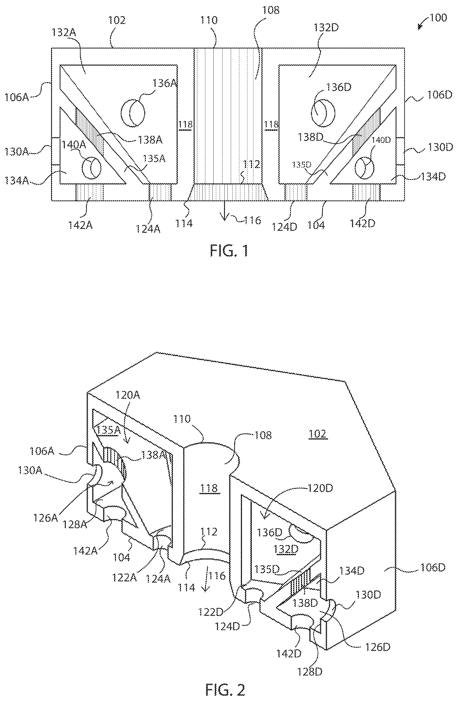
is a side, cross-sectional view of an optional initial stage 100 in accordance with the present invention taken along line AA of .
is a perspective cross-sectional view of the optional initial stage 100 .
is a top perspective view of the optional initial stage 100 .
is a bottom perspective view of the optional initial stage 100 .
is a side, cross-sectional view of first main stage 200 , in accordance with the present invention, taken along line BB of .
is a perspective cross-sectional view of first main stage 200 .
is a top perspective view of the first main stage 200 .
is a bottom perspective view of the first main stage 200 .
is a cross-sectional view of cell 10 , in accordance with the present invention, taken along line CC of , with cell 10 consisting of optional initial stage 100 , first main stage 200 , second main stage (intermediate main stage) 300 , and final main stage 400 .
is a perspective, cross-sectional view of cell 10 in accordance with the present invention.
is a top, perspective view of cell 10 .
is a bottom, perspective view of cell 10 .
is a top, perspective view of an amalgamation of cells 50 in accordance with the present invention.
is a bottom, perspective view of the amalgamation of cells 50 of .
is a perspective view of a sphere 1000 in accordance with the present invention consisting of cells, with the including an x-ray view of an inner chamber Q in which components 500 are located.
is a graphical illustration depicting the sound level L that surrounds sphere 1000 and the sound level in inner chamber Q.
DETAILED DESCRIPTION
With reference to , initial Stage 100 has a top surface 102 and a bottom surface 104 . Top surface 102 and bottom surface 104 connect to sidewalls 106 A and 106 D. A nozzle 108 has an entrance opening 110 , with nozzle 108 being defined by surrounding wall 118 , with surrounding wall 118 connecting to the top surface 102 and to bottom surface 104 of nozzle 108 . The nozzle 108 is cylindrical in shape, with wall 118 tapering outward between cylindrical rings 112 and 114 . Ring 114 at the bottom surface 104 defines an outlet 116 for the exit of sound waves from the initial stage 100 .
Still with reference to , inner chamber wall 132 A and inner chamber wall 132 D are respectively provided with inner chamber passages or holes 136 A, 136 D which acoustically connect the respective inner chambers 120 A, 120 D ( ) with other inner chambers (not shown) of the initial stage 100 . Respective outer chamber walls 134 A, 134 D serve to separate respective outer chambers 126 A, 126 D ( ) from other outer chambers (not shown) that lie within initial stage 100 .
Connecting passage or hole 140 A in outer chamber wall 134 A, and connecting passage or hole 140 D in outer chamber 1324 D respectively connect the outer chamber 126 A and 126 D to other outer chambers within the initial stage 100 . A separating wall 135 A separates inner chamber 120 A from outer chamber 126 A. Inner chamber 120 A and outer chamber 126 A are acoustically connected by hole or passage 138 A which extends through separating wall 135 A. Inner chamber 120 D and outer chamber 126 D are acoustically connected by hole or passage 138 D which extends through separating wall 135 D.
A separating wall 135 D separates inner chamber 120 D from outer chamber 126 D. Inner chamber 120 D and outer chamber 126 D are acoustically connected by hole or passage 138 D which extends through separating wall 135 D. The respective separating walls (e.g. walls 135 A, 135 D) form an oblique angle (i.e., less than 90 degrees) with the floors (floors 122 A, 122 D) of the respective inner chambers.
An outer chamber passage or hole 142 A ( ) extends through the bottom 104 of initial stage 100 for purposes of connecting outer chamber 126 A with a chamber in a subsequent stage to which the initial stage 100 is stacked upon. Outer chamber passage or hole 142 D extends through the bottom 104 of initial stage 100 for purposes of connecting outer chamber 126 D with a chamber in a subsequent stage to which the initial stage 100 is stacked upon.
An inner chamber passage or hole 124 A at the floor 122 A of the inner chamber 126 A extends through the bottom 104 of initial stage 100 for purposes of connecting inner chamber 120 A with a chamber in a subsequent stage to which initial stage 100 is stacked upon. Inner chamber passage or hole 124 D at the floor 122 D of inner chamber 120 D extends through the bottom 104 of initial stage 100 for purposes of connecting inner chamber 120 D with a chamber in a subsequent stage to which initial stage 100 is stacked upon.
is a perspective cross-sectional view that provides additional clarity for the features discussed in respect to . From the top 102 of the initial stage 100 , it can be appreciated that initial stage 100 has a hexagonal shape, with the cylindrical form of the nozzle 108 being fully appreciated. Separating wall 135 A is connected to sidewall 106 A and slopes at an angle to connect with the bottom 104 of the initial stage 100 at a location which is located radially outward from hole 124 A. Separating wall 135 D is connected to sidewall 106 D and slopes at an angle to connect to the bottom 104 of the initial stage 100 at a location located radially outward from hole 124 D. Outer chambers 126 A, 126 D have respective outer floors 128 A, 128 D.
Inner chamber 120 A is acoustically connected to outer chamber 126 A through hole 138 A which is formed in separating wall 135 A, and inner chamber 120 D is acoustically connected to outer chamber 126 D through hole 138 D which is formed in separating wall 135 D. Inner chamber 120 A acoustically connects to a chamber in a subsequent stage through hole 124 A, and inner chamber 120 D acoustically connects to a chamber in a subsequent stage through hole 124 D.
The cylindrical rings 112 and 114 that define the tapered section of the nozzle 108 allow for easy connection to a nozzle section of a subsequent stage upon which the initial stage 100 is stacked. Hole 130 A connects outer chamber 126 A to an adjacent chamber of an adjacent stage of an adjacent cell and, in a like manner, hole 130 D is for purposes of connecting outer chamber 126 D to an adjacent chamber of an adjacent stage of an adjacent cell. Hole 142 A in the bottom of initial stage 100 connects outer stage 126 A to a chamber in a subsequent stage to which initial stage 100 is stacked upon, and hole 142 D in the bottom of initial stage 100 connects outer stage 126 D to a chamber in a subsequent stage to which initial stage 100 is stacked upon.
The hexagonal shape of the initial stage 100 is further appreciated in the top perspective view of and fully visualizes the top edge or ring 110 of the nozzle 108 on top surface 102 . Outer chamber connecting holes 130 A, 130 E and 130 F are positioned in the respective sidewalls and allow sound waves to exit the respective outer chambers and enter the respective outer chambers of an adjacent stage of an adjacent cell.
The bottom perspective view of shows outer chamber connecting holes or passages 142 A, 142 B, 142 C, 142 D, 142 E, 142 F that connect respective outer chambers in the initial stage 100 to respective chambers in a subsequent main stage to which the initial stage is stacked upon. Inner chamber connecting holes or passages 124 A, 124 B, 124 C, 124 D, 124 E, 124 F connect respective inner chambers in the initial stage 100 to respective chambers in a subsequent main stage to which the initial stage is stacked upon.
Attention is now directed to which is a cross-sectional view of first main stage 200 taken along line BB of and to which is a perspective view of the cross-sectional view of . First main stage 200 has a top surface 202 and a bottom surface 204 . Sidewalls 206 A and 206 D connect to top surface 202 and bottom surface 204 . Top surface 202 is provided with holes or passages 215 A, 215 D that acoustically connect to holes 142 A, 142 D, respectively, of the initial stage 100 ( ). Holes 215 A and 215 D acoustically connect to inner chambers 220 A and 220 D, respectively. In a like manner, holes 217 A and 217 D, which are located radially inward from holes 215 A and 215 D, respectively connect to holes 124 A and 124 D of the initial stage 100 , with holes 215 A and 215 D connecting to inner chambers 220 A and 220 D ( ), respectively.
A conically-shaped nozzle 208 is formed by a conical wall 218 . Conical wall 218 forms an entrance opening 210 at the top surface 202 of the first main stage 200 . Conical wall 218 connects to bottom surface 204 of first main stage 200 . Located radially within the bottom outer radius 222 of conical wall 218 are holes 224 A, 224 B, 224 C, 224 D which acoustically connect soundwaves from the nozzle 208 to respective holes or passages in a second main stage (intermediate main stage) 300 .
Holes 224 A, 224 B, 224 C, 224 D are positioned within a peripheral bottom region 223 of nozzle 208 , with peripheral bottom region 223 being formed between outer bottom ring 222 and inner bottom ring 226 which forms outlet hole 216 . Outlet hole 216 is tapered in that lower bottom ring 214 is of a greater radial distance from the axial center of outlet hole 216 than the radial distance of upper-bottom ring 219 so as to allow for a secure connection with a like-shaped intermediate main stage.
Inner chamber dividing walls 232 A, 232 D respectively separate inner chambers 220 A, 220 D from adjacent inner chambers of the first main stage 200 , with the respective holes 236 A, 236 D acoustically connecting adjacent inner chambers (not shown). Separating walls 245 A, 245 D respectively separate inner chamber 220 A from outer chamber 236 A and inner chamber 220 D from outer chamber 236 D.
Holes 238 A, 238 D acoustically connect inner chamber 220 A with outer chamber 226 A and to inner chamber 220 D and outer chamber, respectively. The floor 237 A of the outer chamber 226 A has a hole or passage 242 A that connects to a passage in an intermediate main stage 300 . In a like manner, the floor 237 D of the outer chamber 226 D has a hole or passage 242 D that connects to a passage in the intermediate main stage 300 ( ).
Still with reference to , holes 236 A and 236 D are located in inner chamber dividing walls 232 A and 232 D, respectively, so as to connect respective inner chambers 220 A, 220 D with adjacent inner chambers in main stage 200 . Holes or passages 233 A, 233 D connect respective inner chambers 220 A, 220 D with the upper region of conical nozzle 208 and holes or passages 235 A, 235 D connect the respective inner chambers 220 A, 220 D with the lower region of conical nozzle 208 . Separating walls 245 A, 245 D, respectively separate inner chamber 220 A from outer chamber 226 A and inner chamber 220 D from outer chamber 226 D.
In forming inner chamber 220 A, and lower chamber 226 A, separating wall 245 A connects to sidewall 206 A and slopes at an angle before connecting to conical wall 218 .
In a like manner, in forming inner chamber 220 D, and lower chamber 226 D, separating wall 245 D connects to sidewall 206 D and slopes at an angle before connecting to conical wall 218 . Sidewall 206 A has a hole 230 A for purposes of connecting the outer chamber 226 A to a an adjacent chamber in an adjacent cell and sidewall 206 D has a hole 230 D for purposes of connecting the outer chamber 226 D to a corresponding adjacent chamber in an adjacent cell.
In , the top perspective view of first main stage 200 clearly visualizes top surface 202 . Top surface 202 has holes or passages 215 A, 215 B, 215 C, 215 D, 215 E, 215 F for purposes of connecting to holes or passages 142 A, 142 B, 142 C, 142 D, 142 E, 142 F of the initial stage 100 , so as to acoustically connect the respective outer chambers of the initial stage to the respective inner chambers of the first main stage. In addition, top surface 202 has passages 217 A, 217 B, 217 C, 217 D, 217 E, 217 F that are located radially inward from passages 215 A, 215 B, 215 C, 215 D, 215 E, 215 F.
Passages 217 A, 217 B, 217 C, 217 D, 217 E, 217 F are for purposes of connecting to holes or passages 124 A, 124 B, 124 C, 124 D, 124 E, 124 F located at the bottom of the initial stage 100 so as to acoustically connect the outer chambers of the initial stage to respective inner chambers of the first main stage. further demonstrates exit holes 230 A, 230 E, 230 F located in the respective sidewalls 206 A, 206 E, 206 F.
In the perspective bottom view of , the bottom surface 204 of the first main stage 200 can be clearly appreciated. The bottom surface 204 has 242 A, 242 B, 242 C, 242 D, 242 E, 242 F for purposes of connecting to corresponding holes 315 A, etc., ( ), in the intermediate main stage so as to connect the outer chambers 226 A, 226 D, etc., to the inner chambers 320 A, 320 D, etc., of the intermediate main stage ( ).
Holes 224 A, 224 B, 224 C, 224 D, 224 E, 224 F which are located at the bottom surface 204 of first main stage 200 connect the nozzle 208 to respective holes (e.g., hole 317 A, 317 E, etc.,) of the intermediate main stage. This results in the nozzle 208 of the first main stage 200 being acoustically connected to the respective inner chambers of the intermediate main stage.
is a cross-sectional view of cell 10 that is taken along line CC of . Initial stage 100 is stacked upon first main stage 200 which is stacked upon intermediate main stage 300 which is stacked upon final main stage 400 to form cell 10 . Final stage 400 has a bottom surface 404 , with the bottom edge 414 of nozzle 408 forming the sole acoustic bottom exit from bottom surface 404 of final stage 400 . The geometries of the nozzles of the initial stage, first main stage, intermediate main stage, and final stage allow for a secure and snug modular connection between stages.
In , the perspective view of the cross-section of demonstrates that cell 10 is formed from initial stage 100 which is stacked upon first main stage 200 which is stacked upon intermediate main stage 300 which is stacked upon final stage 400 . From , it is can be fully appreciated that nozzle 208 fits within nozzle 108 and nozzle 308 fits within nozzle 208 and nozzle 408 fits within nozzle 308 for secure assembly of the modular configuration of cell 10 .
In , the top perspective view of cell 10 visualizes three sidewalls of the respective stages 100 , 200 , 300 , and 400 . Holes 130 A, 130 E, 130 F, 230 A, 230 E, 230 F, 330 A, 330 E, 430 A, and 430 F are positioned to connect respective outer chambers with adjacent stages of adjacent cells.
In , the bottom perspective view of cell 10 demonstrates shows bottom surface 404 of the final stage 400 . Sidewall holes 130 A, 130 E, 130 F, 230 A, 230 E, 230 F, 330 A, 330 E, 330 F, 430 A, 430 E, and 430 F acoustically connect the respective outer chambers of cell 10 with adjacent stages of adjacent cells.
In , the top perspective view shows an amalgamation of cells 50 in which cells 10 A, 10 B, 10 C, 10 D, 10 E connect to other cells of the amalgamation of cells.
In , the bottom perspective view shows amalgamation of cells 50 in which cells 10 A, 10 B, 10 C, 10 D, 10 E connect to other cells of the amalgamation of cells.
In , a sphere 1000 is located within an atmosphere that is surrounded by sound waves L. The sphere is constructed from cells 10 A′, 10 B′, 10 C′ which connect to other cells to construct the sphere 1000 . The cells form an interior chamber Q in which is located components 500 . As a result of the cells of the sphere surrounding the chamber Q, the components 500 experience a much reduced sound level than sound level L that is present outside of the sphere.
In , nozzle 108 is shown to be cylindrical in shape and in , nozzles 208 , 308 , 408 are demonstrated to be conical in shape. However, it is understood that the nozzles can take other shapes so long as axial flow of sound waves from one stage to the next stage are accommodated by the nozzle. The nozzle 108 of the optional initial stage does not have holes or passages in the defining wall 118 so that sound waves entering the nozzle 108 are directed to the first stage nozzle 208 . Nozzle 208 of the first main stage 200 has nozzles (e.g. nozzle passages 233 A, 233 D, 235 A, 235 D) that are located radially outward from an axial axis of the nozzle 208 . However, in that the invention does not require the respective nozzles to be cylindrical or conical in shape (with such nozzle shapes having radially-oriented passages), the nozzle passages or holes can be understood as being on the lateral side or sides of the nozzle.
The stages, such as stages 100 , 200 , 300 , 400 can be of virtually any geometric shape so long as the respective modules which constitute the respective stages can be fit together. Also, the nozzles do not necessarily have to be in the geometric center of the respective stages, but can be offset from the geometric center. The number of stages needed for a given cell can be determined by the given circumstances. In one situation a single stage might be sufficient, while situations may call for two, three, four or more stages to adequately filter and reduce the exiting sound waves to a desired level.
The governing equations of the invention can be derived using the fundamental acoustic equations which are as follows. The Conservation of Mass/Continuity equation, Conservation of Momentum Equation and the Isentropic Relationship of an Ideal Gas can be used to derive the wave equation for the final design.
The Conservation of Mass/Continuity Equation is defined as:
∂ ∂ t ( ρ V ) = m . in - m . out ( 1 )
where ρ is density, V is volume, {dot over (m)} is the mass flow rate.
The Conservation of Momentum Equation is defined as:
∂ ∂ t ( ρ u ) = ∇ · ( ρ uu ) = - ∇ P ( 2 )
where ρ is density, u is velocity, P is the pressure.
The Isentropic Relationship of an Ideal Gas is: dP=c 2 dρ (3) where P is the pressure, c is the speed of sound, and ρ is density.
The general form of the wave equation is:
∂ 2 P ∂ t 2 - C 2 ∂ 2 P ∂ x 2 = 0 ( 4 ) where P is the pressure, c is the speed of sound, t is the time, and x is the one dimensional position vector.
The prototype of the present invention was constructed by using a three-dimensional printer with a stage length of 0.25 inches. However, other methods of construction can be used such as traditional machine shop equipment or advanced manufacturing methods
Experimentation has demonstrated that the present invention reduces acoustic noise in both directions, i.e., whether the noise originates from the top or bottom of a cell. In addition, in that the different cells can be formed into various geometric shapes, the invention can provide acoustical protection in all directions.
Still further, since the nozzles of the present invention are not closed off to atmosphere, stored heat can escape a sound-protected space or chamber giving further protection to items, components or personnel.
The stages of the present invention may have no chambers, one chamber, or multiple chambers within a given stage. The number of chambers for the cell structures will be dependent upon the degree of sound-level filtering needed for a given situation. So too, the number of stages for the cell structures will be dependent upon the degree of sound-level filtering needed for a given situation. Some situations may not require an intermediate main stage, while other situations might require one intermediate main stage, or multiple iterations of the intermediate main stage. The outer geometry for the stages and subsequent cells will be dependent upon the given situation.
Various modifications and embodiments of the invention may be made by those skilled in the art without departing from the scope and spirit of the foregoing disclosure. Accordingly, the scope of the invention is limited only by the following claims.
Figures (9)
Citations
This patent cites (5)
- US11835315
- US2016/0071507
- US106205590
- USH-08183122
- USWO-2021194419