Optical System, Optical Apparatus and Method for Manufacturing the Optical System, and Zoom Optical System, Optical Apparatus and Method for Manufacturing the Zoom Optical System
Abstract
This optical system (LS) has an aperture diaphragm (S) and a negative lens (L 4 ) disposed closer to an object side than the aperture diaphragm (S) and satisfies the following conditional expression. −0.010< ndN 1−(2.015−0.0068×ν dN 1), 50.00<ν dN 1<65.00, 0.545<θ gFN 1, −0.010<θ gFN 1−(0.6418−0.00168×ν dN 1). Where, ndN1 is a refractive index of the negative lens with respect to a d-line, νdN1 is an Abbe number of the negative lens based on the d-line, and θgFN1 is a partial dispersion ratio of the negative lens.
Claims (20)
1. An optical system, comprising: an aperture stop; and a negative lens disposed in a lens group having negative refractive power, the lens group being disposed closer to an object than the aperture stop, wherein the negative lens satisfies the following conditional expressions: 50.00<ν dN 1<65.00, 0.545<θ gFN 1≤0.55837, −0.010< θgFN 1−(0.6418−0.00168 ×νdN 1), where νdN1: an Abbe number of the negative lens with reference to d-line, and θgFN1: a partial dispersion ratio of the negative lens, defined by a following expression when a refractive index of the negative lens for g-line is ngN1, a refractive index of the negative lens for F-line is nFN1, and a refractive index of the negative lens for C-line is nCN1: θ gFN 1=( ngN 1− nFN 1)/( nFN 1− nCN 1).
10. A method for manufacturing an optical system, the method comprises a step of arranging, in a lens barrel, an aperture stop, and a lens group having negative refractive power and including a negative lens, the lens group being disposed closer to an object than the aperture stop, the negative lens satisfying the following conditional expressions: 50.00<ν dN 1<65.00, 0.545<θ gFN 1≤0.55837, −0.010< θgFN 1−(0.6418−0.00168 ×νdN 1), where νdN1: an Abbe number of the negative lens with reference to d-line, and θgFN1: a partial dispersion ratio of the negative lens, defined by a following expression when a refractive index of the negative lens for g-line is ngN1, a refractive index of the negative lens for F-line is nFN1, and a refractive index of the negative lens for C-line is nCN1: θ gFN 1=( ngN 1− nFN 1)/( nFN 1− nCN 1).
11. A zoom optical system, comprising a plurality of lens groups that include lens groups having negative refractive powers, wherein upon zooming, a distance between the lens groups adjacent to each other changes, and an object-side negative lens group disposed closest to an object among the lens groups having the negative refractive powers includes a negative lens that satisfies the following conditional expressions: 50.00<ν dN 3<65.00, 0.545<θ gFN 3≤0.55837, −0.010< θgFN 3−(0.6418−0.00168 ×νdN 3), where νdN3: an Abbe number of the negative lens with reference to d-line, and θgFN3: a partial dispersion ratio of the negative lens, defined by a following expression when a refractive index of the negative lens for g-line is ngN3, a refractive index of the negative lens for F-line is nFN3, and a refractive index of the negative lens for C-line is nCN3: θ gFN 3=( ngN 3− nFN 3)/( nFN 3− nCN 3).
20. A method for manufacturing a zoom optical system that includes a plurality of lens groups including lens groups having negative refractive powers, the method comprises a step of arranging the plurality of lens groups in a lens barrel so that upon zooming, a distance between the lens groups adjacent to each other changes, and an object-side negative lens group disposed closest to an object among the lens groups having the negative refractive powers includes a negative lens that satisfies the following conditional expressions: 50.00<ν dN 3<65.00, 0.545<θ gFN 3≤0.55837, −0.010< θgFN 3−(0.6418−0.00168 ×νdN 3), where νdN3: an Abbe number of the negative lens with reference to d-line, and θgFN3: a partial dispersion ratio of the negative lens, defined by a following expression when a refractive index of the negative lens for g-line is ngN3, a refractive index of the negative lens for F-line is nFN3, and a refractive index of the negative lens for C-line is nCN3: θ gFN 3=( ngN 3− nFN 3)/( nFN 3− nCN 3).
Show 16 dependent claims
2. The optical system according to claim 1 , consisting of: the aperture stop; a front group disposed closer to the object than the aperture stop; and a rear group disposed closer to an image than the aperture stop, wherein the front group includes the negative lens and satisfies the following conditional expression: −10.00<(− fN 1)/ fF< 10.00, where fN1: a focal length of the negative lens, and fF: a focal length of the front group; in a case where the optical system is a zoom optical system, the focal length of the front group in a wide angle end state.
3. The optical system according to claim 1 , wherein the negative lens satisfies the following conditional expression: 0.10<(− fN 1)/ f< 15.00, where fN1: the focal length of the negative lens, and f: a focal length of the optical system; in a case where the optical system is a zoom optical system, the focal length of the optical system in a wide angle end state.
4. The optical system according to claim 1 , wherein the negative lens satisfies the following conditional expression: 0.010<θ gFN 1−(0.6418−0.00168×ν dN 1).
5. The optical system according to claim 1 , wherein the negative lens satisfies the following conditional expression: DN 1>0.400 [mm] where DN1: a thickness of the negative lens on an optical axis.
6. The optical system according to claim 1 , wherein the negative lens is a single lens, or one lens of two lenses of a cemented lens consisting of the two lenses cemented to each other.
7. The optical system according to claim 1 , wherein at least one lens surface of an object-side lens surface and an image-side lens surface of the negative lens is in contact with air.
8. The optical system according to claim 1 , wherein the negative lens is a glass lens.
9. An optical apparatus comprising the optical system according to claim 1 .
12. The zoom optical system according to claim 11 , wherein the negative lens satisfies the following conditional expression: 0.50< fN 3/ fGa< 7.00 where fN3: the focal length of the negative lens, and fGa: a focal length of the object-side negative lens group.
13. The zoom optical system according to claim 11 , wherein the object-side negative lens group satisfies the following conditional expression: 0.20<(− fGa )/ f< 3.50 where fGa: a focal length of the object-side negative lens group, and f: a focal length of the zoom optical system in a wide angle end state.
14. The zoom optical system according to claim 11 , wherein the negative lens satisfies the following conditional expression: 0.010<θ gFN 3−(0.6418−0.00168×ν dN 3).
15. The zoom optical system according to claim 11 , wherein the negative lens satisfies the following conditional expression: DN 3>0.400 [mm] where DN3: a thickness of the negative lens on an optical axis.
16. The zoom optical system according to claim 11 , wherein the negative lens is a single lens, or one lens of two lenses of a cemented lens consisting of the two lenses cemented to each other.
17. The zoom optical system according to claim 11 , wherein at least one lens surface of an object-side lens surface and an image-side lens surface of the negative lens is in contact with air.
18. The zoom optical system according to claim 11 , wherein the negative lens is a glass lens.
19. An optical apparatus comprising the zoom optical system according to claim 11 .
Full Description
Show full text →
TECHNICAL FIELD
The present invention relates to an optical system, an optical apparatus and a method for manufacturing the optical system, and a zoom optical system, an optical apparatus, and a method for manufacturing the zoom optical system.
TECHNICAL BACKGROUND
In recent years, the image resolutions of imaging elements included in imaging apparatuses, such as digital cameras and video cameras, have been improved. It is desired that a photographing lens provided in an imaging apparatus including such an imaging element be a lens of which not only the reference aberrations (aberrations for single-wavelength aberrations), such as the spherical aberration and the coma aberration, be favorably corrected, but also chromatic aberrations be favorably corrected so as not to cause color bleeding for a white light source, and which have a high resolution. In particular, for correction of the chromatic aberrations, it is desirable that not only primary achromatism be achieved but also secondary spectrum be favorably corrected. As means for correcting the chromatic aberrations, for example, a method of using a resin material having anomalous dispersion characteristics (for example, see Patent literature 1) has been known. As described above, accompanied by the recent improvement in imaging element resolution, a photographing lens with various aberrations being favorably corrected has been desired.
PRIOR ARTS LIST
Patent Document
Patent literature 1: Japanese Laid-Open Patent Publication No. 2016-194609(A)
SUMMARY OF THE INVENTION
The optical system according to the present invention comprises: an aperture stop; and a negative lens that is disposed closer to an object than the aperture stop. The negative lens satisfies the following conditional expressions, −0.010< ndN 1−(2.015−0.0068 ×νdN 1), 50.00<ν dN 1<65.00, 0.545<θ gFN 1, −0.010< θgFN 1−(0.6418−0.00168 ×νdN 1),
•
• where ndN1: a refractive index of the negative lens for d-line, • νdN1: an Abbe number of the negative lens with reference to d-line, and • θgFN1: a partial dispersion ratio of the negative lens, defined by a following expression when a refractive index of the negative lens for g-line is ngN1, a refractive index of the negative lens for F-line is nFN1, and a refractive index of the negative lens for C-line is nCN1: θ gFN 1=( ngN 1 −nFN 1)/( nFN 1 −nCN 1).
The optical apparatus according to the present invention comprises the optical system described above.
A method for manufacturing an optical system according to the present invention comprises a step of arranging each lens in a lens barrel so that the optical system comprises: an aperture stop; and a negative lens that is disposed closer to an object than the aperture stop, the negative lens satisfying the following conditional expressions, −0.010< ndN 1−(2.015−0.0068 ×νdN 1), 50.00<ν dN 1<65.00, 0.545<θ gFN 1, −0.010< θgFN 1−(0.6418−0.00168 ×νdN 1),
•
• where ndN1: a refractive index of the negative lens for d-line, • νdN1: an Abbe number of the negative lens with reference to d-line, and • θgFN1: a partial dispersion ratio of the negative lens, defined by a following expression when a refractive index of the negative lens for g-line is ngN1, a refractive index of the negative lens for F-line is nFN1, and a refractive index of the negative lens for C-line is nCN1: θ gFN 1=( ngN 1 −nFN 1)/( nFN 1 −nCN 1).
A zoom optical system according to the present invention comprises: a plurality of lens groups that include lens groups having negative refractive powers, wherein upon zooming, a distance between the lens groups adjacent to each other changes, and an object-side negative lens group disposed closest to an object among the lens groups having the negative refractive powers includes a negative lens that satisfies the following conditional expressions, −0.010< ndN 3−(2.015−0.0068 ×νdN 3), 50.00<ν dN 3<65.00, 0.545<θ gFN 3, −0.010< θgFN 3−(0.6418−0.00168 ×νdN 3),
•
• where ndN3: a refractive index of the negative lens for d-line, • νdN3: an Abbe number of the negative lens with reference to d-line, and • θgFN3: a partial dispersion ratio of the negative lens, defined by a following expression when a refractive index of the negative lens for g-line is ngN3, a refractive index of the negative lens for F-line is nFN3, and a refractive index of the negative lens for C-line is nCN3: θ gFN 3=( ngN 3 −nFN 3)/( nFN 3 −nCN 3).
The optical apparatus according to the present invention comprises the zoom optical system described above.
A method for manufacturing a zoom optical system that includes a plurality of lens groups including lens groups having negative refractive powers according to the present invention. The method comprises a step of arranging each lens in a lens barrel so that upon zooming, a distance between the lens groups adjacent to each other changes, and an object-side negative lens group disposed closest to an object among the lens groups having the negative refractive powers includes a negative lens that satisfies the following conditional expressions, −0.010< ndN 3−(2.015−0.0068 ×νdN 3), 50.00<ν dN 3<65.00, 0.545<θ gFN 3, −0.010< θgFN 3−(0.6418−0.00168 ×νdN 3),
•
• where ndN3: a refractive index of the negative lens for d-line, • νdN3: an Abbe number of the negative lens with reference to d-line, and • θgFN3: a partial dispersion ratio of the negative lens, defined by a following expression when a refractive index of the negative lens for g-line is ngN3, a refractive index of the negative lens for F-line is nFN3, and a refractive index of the negative lens for C-line is nCN3: θ gFN 3=( ngN 3 −nFN 3)/( nFN 3 −nCN 3).
BRIEF DESCRIPTION OF THE DRAWINGS
is a lens configuration diagram of an optical system in a state upon focusing on infinity according to First Example;
A, 2 B and 2 C are graphs respectively showing various aberrations of the optical system according to First Example upon focusing on infinity, upon focusing on an intermediate distant object and upon focusing on a short distant object;
is a lens configuration diagram of an optical system in a state upon focusing on infinity according to Second Example;
A, 4 B and 4 C are graphs respectively showing various aberrations of the optical system according to Second Example upon focusing on infinity in the wide-angle end state, the intermediate focal length state and the telephoto end state;
is a lens configuration diagram of an optical system in a state upon focusing on infinity according to Third Example;
A, 6 B and 6 C are graphs respectively showing various aberrations of the optical system according to Third Example upon focusing on infinity in the wide-angle end state, the intermediate focal length state and the telephoto end state;
is a lens configuration diagram of an optical system in a state upon focusing on infinity according to Fourth Example;
A, 8 B and 8 C are graphs respectively showing various aberrations of the optical system according to Fourth Example upon focusing on infinity in the wide-angle end state, the intermediate focal length state and the telephoto end state;
is a lens configuration diagram of an optical system in a state upon focusing on infinity according to Fifth Example;
A, 10 B and 10 C are graphs respectively showing various aberrations of the optical system according to Fifth Example upon focusing on infinity in the wide-angle end state, the intermediate focal length state and the telephoto end state;
is a lens configuration diagram of an optical system in a state upon focusing on infinity according to Sixth Example;
A, 12 B and 12 C are graphs respectively showing various aberrations of the optical system according to Sixth Example upon focusing on infinity in the wide-angle end state, the intermediate focal length state and the telephoto end state;
is a lens configuration diagram of an optical system in a state upon focusing on infinity according to Seventh Example;
A, 14 B and 14 C are graphs respectively showing various aberrations of the optical system according to Seventh Example upon focusing on infinity in the wide-angle end state, the intermediate focal length state and the telephoto end state;
is a lens configuration diagram of an optical system in a state upon focusing on infinity according to Eighth Example;
A, 16 B and 16 C are graphs respectively showing various aberrations of the optical system according to Eighth Example upon focusing on infinity in the wide-angle end state, the intermediate focal length state and the telephoto end state;
is a lens configuration diagram of an optical system in a state upon focusing on infinity according to Ninth Example;
A, 18 B and 18 C are graphs respectively showing various aberrations of the optical system according to Ninth Example upon focusing on infinity in the wide-angle end state, the intermediate focal length state and the telephoto end state;
is a lens configuration diagram of an optical system in a state upon focusing on infinity according to Tenth Example;
A, 20 B and 20 C are graphs respectively showing various aberrations of the optical system according to Tenth Example upon focusing on infinity in the wide-angle end state, the intermediate focal length state and the telephoto end state;
is a lens configuration diagram of an optical system in a state upon focusing on infinity according to Eleventh Example;
A, 22 B and 22 C are graphs respectively showing various aberrations of the optical system according to Eleventh Example upon focusing on infinity in the wide-angle end state, the intermediate focal length state and the telephoto end state;
shows a configuration of a camera that includes the optical system according to each embodiment;
is a flowchart showing a method of manufacturing the optical system according to a first embodiment; and
is a flowchart showing a method of manufacturing the optical system (zoom optical system) according to a second embodiment.
DESCRIPTION OF THE EMBODIMENTS
Hereinafter, preferable embodiments according to the present invention are described. First, a camera (optical apparatus) that includes an optical system according to each embodiment is described with reference to . As shown in , the camera 1 is a digital camera that includes the optical system according to each embodiment, as a photographing lens 2 . In the camera 1 , light from an object (photographic subject), not shown, is collected by the photographing lens 2 , and reaches an imaging element 3 . Accordingly, the light from the photographic subject is captured by the imaging element 3 , and is recorded as a photographic subject image in a memory, not shown. As described above, a photographer can take the image of the photographic subject through the camera 1 . Note that this camera may be a mirrorless camera, or a single-lens reflex camera that includes a quick return mirror.
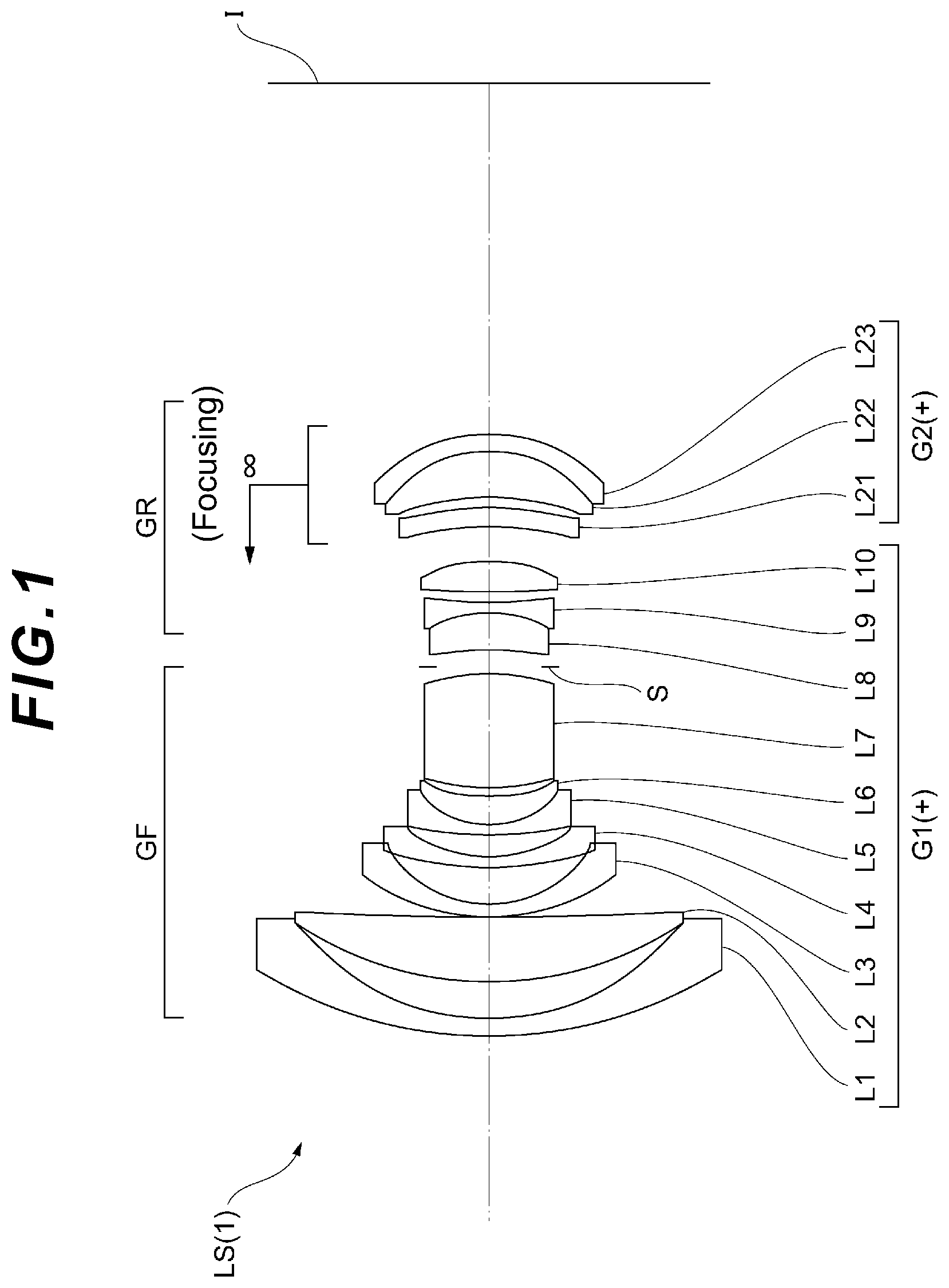
Next, the optical system according to a first embodiment is described. As shown in , an optical system LS( 1 ) as an example of an optical system (photographing lens) LS according to the first embodiment comprises: an aperture stop S; and a negative lens (L 4 ) that is disposed closer to an object than the aperture stop S, and satisfies following conditional expressions (1) to (4). −0.010< ndN 1−(2.015−0.0068 ×νdN 1), (1) 50.00<ν dN 1<65.00, (2) 0.545<θ gFN 1, (3) −0.010< θgFN 1−(0.6418−0.00168 ×νdN 1), (4)
•
• where ndN1: is a refractive index of the negative lens for d-line, • νdN1: an Abbe number of the negative lens with reference to d-line, and • θgFN1: a partial dispersion ratio of the negative lens, defined by a following expression when a refractive index of the negative lens for g-line is ngN1, a refractive index of the negative lens for F-line is nFN1, and a refractive index of the negative lens for C-line is nCN1: θ gFN 1=( ngN 1 −nFN 1)/( nFN 1 −nCN 1).
Note that the Abbe number νdN1 of the negative lens with reference to d-line is defined by the following expression: ν dN 1=( ndN 1−1)/( nFN 1 −nCN 1).
According to the first embodiment, the optical system where for correction of chromatic aberrations, in addition to primary achromatization, the secondary spectrum is favorably corrected, and the optical apparatus that includes this optical system can be achieved. The optical system LS according to the first embodiment may be an optical system LS( 2 ) shown in , an optical system LS( 3 ) shown in , an optical system LS( 4 ) shown in , an optical system LS( 5 ) shown in , or an optical system LS( 6 ) shown in . The optical system LS according to the first embodiment may be an optical system LS( 7 ) shown in , an optical system LS( 8 ) shown in , an optical system LS( 9 ) shown in , an optical system LS( 10 ) shown in , or an optical system LS( 11 ) shown in .
The conditional expression (1) defines an appropriate relationship between the refractive index of the negative lens for d-line and the Abbe number with reference to d-line. By satisfying the conditional expression (1), correction of the reference aberrations, such as the spherical aberration and the coma aberration, and correction of the primary chromatic aberration can be favorably performed.
If the corresponding value of the conditional expression (1) falls outside of the range, the correction of the chromatic aberrations becomes difficult. By setting the lower limit value of the conditional expression (1) to −0.005, the advantageous effects of this embodiment can be further secured. To further secure the advantageous effects of this embodiment, the lower limit value of the conditional expression (1) may be set to −0.001, 0.000, 0.003, 0.005 or 0.007, or further to 0.008.
Note that the upper limit value of the conditional expression (1) may be set to less than 0.150. Accordingly, correction of the reference aberrations, such as the spherical aberration and the coma aberration, and correction of the primary chromatic aberration (achromatization) can be favorably performed. In this case, by setting the upper limit value of the conditional expression (1) to 0.100, the advantageous effects of this embodiment can be further secured. To further secure the advantageous effects of this embodiment, the upper limit value of the conditional expression (1) may be set to 0.080, 0.060 or 0.050, or further to 0.045.
The conditional expression (2) defines an appropriate range of the Abbe number of the negative lens with reference to d-line. By satisfying the conditional expression (2), correction of the reference aberrations, such as the spherical aberration and the coma aberration, and correction of the primary chromatic aberration (achromatization) can be favorably performed.
If the corresponding value of the conditional expression (2) falls outside of the range, the correction of the chromatic aberrations becomes difficult. By setting the lower limit value of the conditional expression (2) to 50.50, the advantageous effects of this embodiment can be further secured. To further secure the advantageous effects of this embodiment, the lower limit value of the conditional expression (2) may be set to 51.00, 51.50 or 52.00, or further to 52.40.
By setting the upper limit value of the conditional expression (2) to 64.00, the advantageous effects of this embodiment can be further secured. To further secure the advantageous effects of this embodiment, the upper limit value of the conditional expression (2) may be set to 63.00, 62.50, 62.00, 61.50, 61.00 or 60.00, or further to 59.50.
The conditional expression (3) appropriately defines the anomalous dispersion characteristics of the negative lens. By satisfying the conditional expression (3), for correction of chromatic aberrations, in addition to primary achromatization, the secondary spectrum can be favorably corrected.
If the corresponding value of the conditional expression (3) falls outside of the range, the correction of the chromatic aberrations becomes difficult. By setting the lower limit value of the conditional expression (3) to 0.547, the advantageous effects of this embodiment can be further secured. To further secure the advantageous effects of this embodiment, the lower limit value of the conditional expression (3) may be set to 0.548 or 0.549, or further to 0.550.
The conditional expression (4) appropriately defines the anomalous dispersion characteristics of the negative lens. By satisfying the conditional expression (4), for correction of chromatic aberrations, in addition to primary achromatization, the secondary spectrum can be favorably corrected.
If the corresponding value of the conditional expression (4) falls outside of the range, the correction of the chromatic aberrations becomes difficult. By setting the lower limit value of the conditional expression (4) to −0.005, the advantageous effects of this embodiment can be further secured. To further secure the advantageous effects of this embodiment, the lower limit value of the conditional expression (4) may be set to −0.001.
Note that the upper limit value of the conditional expression (4) may be set to less than 0.040. Accordingly, correction of the reference aberrations, such as the spherical aberration and the coma aberration, and correction of the primary chromatic aberration (achromatization) can be favorably performed. In this case, by setting the upper limit value of the conditional expression (4) to 0.030, the advantageous effects of this embodiment can be further secured. To further secure the advantageous effects of this embodiment, the upper limit value of the conditional expression (4) may be set to 0.025, or further to 0.020.
Preferably, the optical system LS according to the first embodiment consists of: the aperture stop S; a front group GF disposed closer to the object than the aperture stop S; and a rear group GR disposed closer to an image than the aperture stop S, wherein the front group GF, which includes the negative lens, satisfies the following conditional expression (5), −10.00<(− fN 1)/ fF< 10.00, (5)
where fN1: the focal length of the negative lens, and
fF: a focal length of the front group GF; the focal length of the front group GF in the wide angle end state in a case where the optical system LS is a zoom optical system.
The conditional expression (5) defines an appropriate relationship between the focal length of the negative lens and the focal length of the front group GF. By satisfying the conditional expression (5), the reference aberrations, such as the spherical aberration and the coma aberration, can be favorably corrected.
If the corresponding value of the conditional expression (5) falls outside of the range, the correction of the reference aberrations, such as the spherical aberration and the coma aberration, becomes difficult. By setting the lower limit value of the conditional expression (5) to −9.50, the advantageous effects of this embodiment can be further secured. To further secure the advantageous effects of this embodiment, the lower limit value of the conditional expression (5) may be set to −9.00, −8.50, −8.00, −7.00, −5.00, −3.00, −1.50, −0.05 or 0.05, or further to 0.10.
By setting the upper limit value of the conditional expression (5) to 8.50, the advantageous effects of this embodiment can be further secured. To further secure the advantageous effects of this embodiment, the upper limit value of the conditional expression (5) may be set to 7.50, 6.50, 5.00 or 4.00, or further to 3.00.
In the optical system LS according to the first embodiment, preferably, the negative lens satisfies the following conditional expression (6), 0.10<(− fN 1)/ f< 15.00 (6)
where fN1: the focal length of the negative lens, and
f: a focal length of the optical system; the focal length of the optical system LS in the wide angle end state in a case where the optical system LS is a zoom optical system.
The conditional expression (6) defines an appropriate relationship between the focal length of the negative lens and the focal length of the optical system LS. By satisfying the conditional expression (6), the reference aberrations, such as the spherical aberration and the coma aberration, can be favorably corrected.
If the corresponding value of the conditional expression (6) falls outside of the range, the correction of the reference aberrations, such as the spherical aberration and the coma aberration, becomes difficult. By setting the lower limit value of the conditional expression (6) to 0.20, the advantageous effects of this embodiment can be further secured. To further secure the advantageous effects of this embodiment, the lower limit value of the conditional expression (6) may be set to 0.30, 0.40 or 0.45, or further to 0.50.
By setting the upper limit value of the conditional expression (6) to 14.20, the advantageous effects of this embodiment can be further secured. To further secure the advantageous effects of this embodiment, the upper limit value of the conditional expression (6) may be set to 12.00, 10.00 or 8.50, or further to 7.50.
In the optical system LS according to the first embodiment, the negative lens may satisfy the following conditional expression (3-1), 0.555<θ gFN 1. (3-1)
The conditional expression (3-1) is an expression similar to the conditional expression (3), and can exert advantageous effects similar to those of the conditional expression (3). By setting the lower limit value of the conditional expression (3-1) to 0.556, the advantageous effects of this embodiment can be further secured. To further secure the advantageous effects of this embodiment, it is preferable to set the lower limit value of the conditional expression (3-1) to 0.557.
In the optical system LS according to the first embodiment, the negative lens may satisfy the following conditional expression (4-1), 0.010< θgFN 1−(0.6418−0.00168 ×νdN 1). (4-1)
The conditional expression (4-1) is an expression similar to the conditional expression (4), and can exert advantageous effects similar to those of the conditional expression (4). By setting the lower limit value of the conditional expression (4-1) to 0.011, the advantageous effects of this embodiment can be further secured. To further secure the advantageous effects of this embodiment, it is preferable to set the lower limit value of the conditional expression (4-1) to 0.012.
Note that the upper limit value of the conditional expression (4-1) may be set to less than 0.030. Accordingly, advantageous effects similar to those of the conditional expression (4) can be achieved. In this case, by setting the upper limit value of the conditional expression (4-1) to 0.028, the advantageous effects of this embodiment can be further secured. To further secure the advantageous effects of this embodiment, the upper limit value of the conditional expression (4-1) may be set to 0.025 or 0.023, or further to 0.020.
In the optical system LS according to the first embodiment, preferably, the negative lens satisfies the following conditional expression (7), DN 1>0.400 [mm] (7)
where DN1: a thickness of the negative lens on an optical axis.
The conditional expression (7) appropriately defines the thickness of the negative lens on the optical axis. By satisfying the conditional expression (7), the various aberrations, such as the coma aberration, the chromatic aberrations (the longitudinal chromatic aberration and the chromatic aberration of magnification), can be favorably corrected.
If the corresponding value of the conditional expression (7) falls outside of the range, the correction of the various aberrations, such as the coma aberration and the chromatic aberrations (the longitudinal chromatic aberration and the chromatic aberration of magnification), becomes difficult. By setting the lower limit value of the conditional expression (7) to 0.450 [mm], the advantageous effects of this embodiment can be further secured. To further secure the advantageous effects of this embodiment, the lower limit value of the conditional expression (7) may be set to 0.490 [mm], 0.550 [mm], 0.580 [mm], 0.650 [mm], 0.680 [mm], 0.750 [mm], 0.800 [mm], 0.850 [mm], 0.880 [mm], 0.950 [mm], 0.980 [mm], 1.050 [mm], 1.100 [mm], 1.140 [mm], 1.250 [mm], or further to 1.350 [mm].
In the optical system LS according to the first embodiment, preferably, the negative lens is a single lens, or one lens of two lenses of a cemented lens consisting of the two lenses cemented to each other. Use of glass as the material of the lens has smaller variation in optical characteristics due to temperature than that of resin. In this embodiment, glass can be used as a material of the negative lens. Accordingly, even in the case where the negative lens has a lens surface in contact with air (i.e., a single lens, or one lens of two lenses of a cemented lens consisting of the two lenses cemented to each other), it is preferable because variation in optical characteristics due to temperature is small.
In the optical system LS according to the first embodiment, it is desirable that at least one lens surface of an object-side lens surface and an image-side lens surface of the negative lens be in contact with air. Use of glass as the material of the lens has smaller variation in optical characteristics due to temperature than that of resin. In this embodiment, glass can be used as a material of the negative lens. Accordingly, even in a case where a lens surface of the negative lens is in contact with air, it is preferable because the variation in optical characteristics due to temperature is small.
In the optical system LS according to the first embodiment, it is desirable that the negative lens be a glass lens. The secular change of the negative lens that is a glass lens is smaller than that of a resin lens. Accordingly, it is preferable because the variation in optical characteristics due to temperature is small.
Subsequently, referring to , a method for manufacturing the optical system LS according to the first embodiment is schematically described. First, an aperture stop S, and a negative lens closer to an object than the aperture stop S are arranged (step ST 1 ). At this time, each lens is arranged in a lens barrel so that at least one of the negative lenses arranged closer to the object than the aperture stop S satisfies the conditional expressions (1) to (4) and the like (step ST 2 ). According to such a manufacturing method, the optical system where for correction of chromatic aberrations, in addition to primary achromatization, the secondary spectrum is favorably corrected can be manufactured.
Next, the optical system according to a second embodiment is described. As shown in , the optical system LS( 2 ) as an example of the optical system (photographing lens) LS according to the second embodiment includes a plurality of lens groups that include lens groups having negative refractive powers. Upon zooming, the distance between the lens groups adjacent to each other changes. An object-side negative lens group (a first lens group G 1 ) disposed closest to an object among the lens groups having the negative refractive powers includes a negative lens (L 13 ) that satisfies the following conditional expressions (11) to (14). −0.010< ndN 3−(2.015−0.0068 ×νdN 3), (11) 50.00<ν dN 3<65.00, (12) 0.545<θ gFN 3, (13) −0.010< θgFN 3−(0.6418−0.00168 ×νdN 3), (14)
•
• where ndN3: a refractive index of the negative lens for d-line, • νdN3: an Abbe number of the negative lens with reference to d-line, and • θgFN3: a partial dispersion ratio of the negative lens, defined by a following expression when a refractive index of the negative lens for g-line is ngN3, a refractive index of the negative lens for F-line is nFN3, and a refractive index of the negative lens for C-line is nCN3: θ gFN 3=( ngN 3 −nFN 3)/( nFN 3 −nCN 3).
Note that the Abbe number νdN3 of the negative lens with reference to d-line is defined by the following expression: ν dN 3=( ndN 3−1)/( nFN 3 −nCN 3).
The optical system LS according to the second embodiment is a zoom optical system that performs zooming by changing the distance between lens groups adjacent to each other. According to the second embodiment, the zoom optical system where for correction of chromatic aberrations, in addition to primary achromatization, the secondary spectrum is favorably corrected, and the optical apparatus that includes this zoom optical system can be achieved. The optical system LS (zoom optical system) according to the second embodiment may be an optical system LS( 3 ) shown in , an optical system LS( 4 ) shown in , an optical system LS( 5 ) shown in , or an optical system LS( 6 ) shown in . The optical system LS (zoom optical system) according to the second embodiment may be an optical system LS( 7 ) shown in , an optical system LS( 8 ) shown in , an optical system LS( 9 ) shown in , an optical system LS( 10 ) shown in , or an optical system LS( 11 ) shown in .
The conditional expression (11) defines an appropriate relationship between the refractive index of the negative lens for d-line and the Abbe number with reference to d-line. By satisfying the conditional expression (11), correction of the reference aberrations, such as the spherical aberration and the coma aberration, and correction of the primary chromatic aberration (achromatization) can be favorably performed.
If the corresponding value of the conditional expression (11) falls outside of the range, the correction of the chromatic aberrations becomes difficult. By setting the lower limit value of the conditional expression (11) to −0.005, the advantageous effects of this embodiment can be further secured. To further secure the advantageous effects of this embodiment, the lower limit value of the conditional expression (11) may be set to −0.001, 0.000, 0.003, 0.005 or 0.007, or further to 0.008.
Note that the upper limit value of the conditional expression (11) may be set to less than 0.150. Accordingly, correction of the reference aberrations, such as the spherical aberration and the coma aberration, and correction of the primary chromatic aberration (achromatization) can be favorably performed. In this case, by setting the upper limit value of the conditional expression (11) to 0.100, the advantageous effects of this embodiment can be further secured. To further secure the advantageous effects of this embodiment, the upper limit value of the conditional expression (11) may be set to 0.080, 0.060 or 0.050, or further to 0.045.
The conditional expression (12) defines an appropriate range of the Abbe number of the negative lens with reference to d-line. By satisfying the conditional expression (12), correction of the reference aberrations, such as the spherical aberration and the coma aberration, and correction of the primary chromatic aberration (achromatization) can be favorably performed.
If the corresponding value of the conditional expression (12) falls outside of the range, the correction of the chromatic aberrations becomes difficult. By setting the lower limit value of the conditional expression (12) to 50.50, the advantageous effects of this embodiment can be further secured. To further secure the advantageous effects of this embodiment, the lower limit value of the conditional expression (12) may be set to 51.00, 51.50 or 52.00, or further to 52.40.
By setting the upper limit value of the conditional expression (12) to 64.00, the advantageous effects of this embodiment can be further secured. To further secure the advantageous effects of this embodiment, the upper limit value of the conditional expression (12) may be set to 63.00, 62.50, 62.00, 61.50, 61.00 or 60.00, or further to 59.50.
The conditional expression (13) appropriately defines the anomalous dispersion characteristics of the negative lens. By satisfying the conditional expression (13), for correction of chromatic aberrations, in addition to primary achromatization, the secondary spectrum can be favorably corrected.
If the corresponding value of the conditional expression (13) falls outside of the range, the correction of the chromatic aberrations becomes difficult. By setting the lower limit value of the conditional expression (13) to 0.547, the advantageous effects of this embodiment can be further secured. To further secure the advantageous effects of this embodiment, the lower limit value of the conditional expression (13) may be set to 0.548 or 0.549, or further to 0.550.
The conditional expression (14) appropriately defines the anomalous dispersion characteristics of the negative lens. By satisfying the conditional expression (14), for correction of chromatic aberrations, in addition to primary achromatization, the secondary spectrum can be favorably corrected.
If the corresponding value of the conditional expression (14) falls outside of the range, the correction of the chromatic aberrations becomes difficult. By setting the lower limit value of the conditional expression (14) to −0.005, the advantageous effects of this embodiment can be further secured. To further secure the advantageous effects of this embodiment, the lower limit value of the conditional expression (14) may be set to −0.001.
Note that the upper limit value of the conditional expression (14) may be set to less than 0.040. Accordingly, correction of the reference aberrations, such as the spherical aberration and the coma aberration, and correction of the primary chromatic aberration (achromatization) can be favorably performed. In this case, by setting the upper limit value of the conditional expression (14) to 0.030, the advantageous effects of this embodiment can be further secured. To further secure the advantageous effects of this embodiment, the upper limit value of the conditional expression (14) may be set to 0.025, or further to 0.020.
In the optical system LS (zoom optical system) according to the second embodiment, preferably, the negative lens satisfies the following conditional expression (15), 0.50< fN 3/ fGa< 7.00 (15)
where fN3: the focal length of the negative lens, and
fGa: a focal length of the object-side negative lens group.
The conditional expression (15) defines an appropriate relationship between the focal length of the negative lens and the focal length of the object-side negative lens group. By satisfying the conditional expression (15), the reference aberrations, such as the spherical aberration and the coma aberration, can be favorably corrected.
If the corresponding value of the conditional expression (15) falls outside of the range, the correction of the reference aberrations, such as the spherical aberration and the coma aberration, becomes difficult. By setting the lower limit value of the conditional expression (15) to 0.55, the advantageous effects of this embodiment can be further secured. To further secure the advantageous effects of this embodiment, the lower limit value of the conditional expression (15) may be set to 0.60, 0.65, 0.70, 0.75, 0.80, 0.85, 0.90, 0.95, 1.00 or 1.05, or further to 1.10.
By setting the upper limit value of the conditional expression (15) to 6.50, the advantageous effects of this embodiment can be further secured. To further secure the advantageous effects of this embodiment, the upper limit value of the conditional expression (15) may be set to 6.20, 5.50, 5.00, 4.50, 4.00, 3.80, 3.30, 3.00 or 2.80, or further to 2.30.
In the optical system LS (zoom optical system) according to the second embodiment, preferably, the object-side negative lens group satisfies the following conditional expression (16), 0.20<(− fGa )/ f< 3.50 (16)
where fGa: a focal length of the object-side negative lens group, and
f: a focal length of the zoom optical system LS (zoom optical system) in a wide angle end state.
The conditional expression (16) defines an appropriate relationship between the focal length of the object-side negative lens group and the focal length of the optical system LS (zoom optical system). By satisfying the conditional expression (16), the reference aberrations, such as the spherical aberration and the coma aberration, can be favorably corrected.
If the corresponding value of the conditional expression (16) falls outside of the range, the correction of the reference aberrations, such as the spherical aberration and the coma aberration, becomes difficult. By setting the lower limit value of the conditional expression (16) to 0.25, the advantageous effects of this embodiment can be further secured. To further secure the advantageous effects of this embodiment, the lower limit value of the conditional expression (16) may be set to 0.30, 0.35, 0.40, 0.45 or 0.50, or further to 0.55.
By setting the upper limit value of the conditional expression (16) to 3.30, the advantageous effects of this embodiment can be further secured. To further secure the advantageous effects of this embodiment, the upper limit value of the conditional expression (16) may be set to 3.00, 2.80, 2.65, 2.45 or 2.15, or further to 2.00.
In the optical system LS (zoom optical system) according to the second embodiment, the negative lens may satisfy the following conditional expression (13-1), 0.555<θ gFN 3. (13-1)
The conditional expression (13-1) is an expression similar to the conditional expression (13), and can exert advantageous effects similar to those of the conditional expression (13). By setting the lower limit value of the conditional expression (13-1) to 0.556, the advantageous effects of this embodiment can be further secured. To further secure the advantageous effects of this embodiment, it is preferable to set the lower limit value of the conditional expression (13-1) to 0.557.
In the optical system LS (zoom optical system) according to the second embodiment, the negative lens may satisfy the following conditional expression (14-1), 0.010< θgFN 3−(0.6418−0.00168 ×νdN 3). (14-1)
The conditional expression (14-1) is an expression similar to the conditional expression (14), and can exert advantageous effects similar to those of the conditional expression (14). By setting the lower limit value of the conditional expression (14-1) to 0.011, the advantageous effects of this embodiment can be further secured. To further secure the advantageous effects of this embodiment, it is preferable to set the lower limit value of the conditional expression (14-1) to 0.012.
Note that the upper limit value of the conditional expression (14-1) may be set to less than 0.030. Accordingly, advantageous effects similar to those of the conditional expression (14) can be achieved. In this case, by setting the upper limit value of the conditional expression (14-1) to 0.028, the advantageous effects of this embodiment can be further secured. To further secure the advantageous effects of this embodiment, the upper limit value of the conditional expression (14-1) may be set to 0.025 or 0.023, or further to 0.020.
In the optical system LS (zoom optical system) according to the second embodiment, preferably, the negative lens satisfies the following conditional expression (17), DN 3>0.400 [mm] (17)
where DN3: a thickness of the negative lens on an optical axis.
The conditional expression (17) appropriately defines the thickness of the negative lens on the optical axis. By satisfying the conditional expression (17), the various aberrations, such as the coma aberration, the chromatic aberrations (the longitudinal chromatic aberration and the chromatic aberration of magnification), can be favorably corrected.
If the corresponding value of the conditional expression (17) falls outside of the range, the correction of the various aberrations, such as the coma aberration and the chromatic aberrations (the longitudinal chromatic aberration and the chromatic aberration of magnification), becomes difficult. By setting the lower limit value of the conditional expression (17) to 0.450 [mm], the advantageous effects of this embodiment can be further secured. To further secure the advantageous effects of this embodiment, the lower limit value of the conditional expression (17) may be set to 0.490 [mm], 0.550 [mm], 0.580 [mm], 0.650 [mm], 0.680 [mm], 0.750 [mm], 0.800 [mm], 0.850 [mm], 0.880 [mm], 0.950 [mm], 0.980 [mm], 1.050 [mm], 1.100 [mm], 1.140 [mm] or 1.250 [mm], or further to 1.350 [mm].
In the optical system LS (zoom optical system) according to the second embodiment, preferably, the negative lens is a single lens, or one lens of two lenses of a cemented lens consisting of the two lenses cemented to each other. Use of glass as the material of the lens has smaller variation in optical characteristics due to temperature than that of resin. In this embodiment, glass can be used as a material of the negative lens. Accordingly, even in the case where the negative lens has a lens surface in contact with air (i.e., a single lens, or one lens of two lenses of a cemented lens consisting of the two lenses cemented to each other), it is preferable because variation in optical characteristics due to temperature is small.
In the optical system LS (zoom optical system) according to the second embodiment, at least one lens surface of an object-side lens surface and an image-side lens surface of the negative lens is in contact with air. Use of glass as the material of the lens has smaller variation in optical characteristics due to temperature than that of resin. In this embodiment, glass can be used as a material of the negative lens. Accordingly, even in a case where a lens surface of the negative lens is in contact with air, it is preferable because the variation in optical characteristics due to temperature is small.
In the optical system LS (zoom optical system) according to the second embodiment, it is desirable that the negative lens be a glass lens. The secular change of the negative lens that is a glass lens is smaller than that of a resin lens. Accordingly, it is preferable because the variation in optical characteristics due to temperature is small.
Subsequently, referring to , a method for manufacturing the optical system LS (zoom optical system) according to the second embodiment is schematically described. First, a plurality of lens groups including lens groups having negative refractive powers are arranged (step ST 11 ). The configuration is made so that the distance between lens groups adjacent to each other changes upon zooming (step ST 12 ). Each lens is arranged in the lens barrel so that the object-side negative lens group disposed closest to the object among the lens groups having negative refractive powers includes the negative lens satisfying the conditional expressions (11) to (14) and the like (step ST 13 ). According to such a manufacturing method, the zoom optical system where for correction of chromatic aberrations, in addition to primary achromatization, the secondary spectrum is favorably corrected can be manufactured.
EXAMPLES
Optical systems LS according to Examples of each embodiment are described with reference to the drawings. Note that Examples corresponding to the first embodiment are First to Eleventh Examples, and Examples corresponding to the second embodiment are Second to Eleventh Examples. , 3 , 5 , 7 , 9 , 11 , 13 , 15 , 17 , 19 and 21 are sectional views showing the configurations and refractive power allocations of optical systems LS {LS ( 1 ) to LS ( 11 )} according to First to Eleventh Examples. In the sectional views of the optical systems LS( 1 ) to LS( 11 ) according to First to Eleventh Examples, the moving direction upon focusing by each focusing lens group from the infinity to a short-distance object is indicated by an arrow accompanied by characters “FOCUSING”. The optical system LS( 2 ) to ( 11 ) according to Second to Eleventh Examples are zoom optical systems that perform zooming by changing the distance between lens groups adjacent to each other. In the sectional views of the optical systems LS( 2 ) to LS( 11 ) according to Second to Eleventh Examples, the moving direction of each lens group along the optical axis upon zooming from the wide angle end state (W) to the telephoto end state (T) is indicated by an arrow.
In , 3 , 5 , 7 , 9 , 11 , 13 , 15 , 17 , 19 and 21 , each lens group is represented by a combination of a symbol G and a numeral, and each lens is represented by a combination of a symbol L and a numeral. In this case, to prevent complication due to increase in the types and numbers of symbols and numerals, the lens groups and the like are represented using the combinations of symbols and numerals independently on an Example-by-Example basis. Accordingly, even when the same combination of a symbol and a numeral is used among Examples, such usage does not mean the same configuration.
Tables 1 to 11 are shown below. Among the drawings, Table 1 is a table showing each data item in First Example, Table 2 is that in Second Example, Table 3 is that in Third Example, Table 4 is that in Fourth Example, Table 5 is that in Fifth Example, Table 6 is that in Sixth Example, Table 7 is that in Seventh Example, Table 8 is that in Eighth Example, Table 9 is that in Ninth Example, Table 10 is that in Tenth Example, and Table 11 is that in Eleventh Example. In each Example, as targets of calculation of aberration characteristics, d-line (wavelength λ=587.6 nm), g-line (wavelength λ=435.8 nm), C-line (wavelength λ=656.3 nm), and F-line (wavelength λ=486.1 nm) are selected.
In the table of [General Data], f indicates the focal length of the entire lens system, FNO indicates the f-number, 2ω indicates the angle of view (the unit is ° (degrees), and ω is the half angle of view), and Y indicates the image height. TL indicates a distance obtained by adding BF to the distance from the lens foremost surface to the lens last surface on the optical axis upon focusing on infinity. BF indicates the distance (back focus) from the lens last surface to the image surface I on the optical axis upon focusing on infinity. fF indicates the focal length of the front group, and fR indicates the focal length of the rear group. Note that in a case where the optical system is a zoom optical system, these values are indicated for each of zoom states at the wide-angle end (W), the intermediate focal length (M) and the telephoto end (T).
In the table of [Lens Data], Surface Number indicates the order of the optical surface from the object side along the direction in which the ray travels, R indicates the radius of curvature (the surface whose center of curvature resides on the image side is regarded to have a positive value) of each optical surface, D indicates the surface distance which is the distance to the next lens surface (or the image surface) from each optical surface on the optical axis, nd is the refractive index of the material of the optical member for d-line, νd indicates the Abbe number of the material of the optical member with respect to d-line, and θgF indicates the partial dispersion ratio of the material of the optical member. The radius of curvature “∞” indicates a plane or an opening. (Aperture Stop S) indicates an aperture stop S. The description of the air refractive index nd=1.00000 is omitted. In a case where the optical surface is an aspherical surface, the surface number is assigned * symbol, and the field of the radius of curvature R indicates the paraxial radius of curvature.
The refractive index of the optical member for g-line (wavelength λ=435.8 nm) is indicated by ng. The refractive index of the optical member for F-line (wavelength λ=486.1 nm) is indicated by nF. The refractive index of the optical member for C-line (wavelength λ=656.3 nm) is indicated by nC. Here, the partial dispersion ratio θgF of the material of the optical member is defined by the following expression (A). θ gF =( ng−nF )/( nF−nC ). (A)
In the table of [Aspherical Data], the shape of the aspherical surface indicated in [Lens Data] is indicated by the following expression (B). X(y) indicates the distance (sag amount) from the tangent plane at the vertex of the aspherical surface to the position on the aspherical surface at the height y along the optical axis direction. R indicates the radius of curvature (paraxial radius of curvature) of the reference spherical surface. κ indicates the conic constant. Ai indicates the i-th aspherical coefficient. “E-n” indicates “×10 −n ”. For example, 1.234E−05=1.234×10 −5 . Note that the second-order aspherical coefficient A2 is zero, and the description thereof is omitted. X ( y )=( y 2 /R )/{1+(1 −κ×y 2 /R 2 ) 1/2 }+A 4 ×y 4 +A 6 ×y 6 +A 8 ×y 8 +A 10 ×y 10 +A 12 ×y 12 . (B)
In a case where the optical system is not a zoom optical system, f indicates the focal length of the entire lens system, and β indicates the photographing magnification, as [Variable Distance Data on Short-Distance Photographing]. The table of [Variable Distance Data on Short-Distance Photographing] indicates the surface distance at the surface number where the surface distance is “Variable” in [Lens Data] corresponding to each focal length and photographing magnification.
In the case where the optical system is the zoom optical system, the surface distance at the surface number where the surface distance is “Variable” in [Lens Data] corresponding to each of zooming states at the wide angle end (W), the intermediate focal length (M) and the telephoto end (T) are indicated as [Variable Distance Data on Zoom Photographing].
The table of [Lens Group Data] shows the first surface (the surface closest to the object) and the focal length of each lens group.
The table of [Conditional Expression Corresponding Value] shows the value corresponding to each conditional expression.
Hereinafter, at all the data values, the listed focal length f, the radius of curvature R, the surface distance D, other lengths and the like are represented with “mm” if not otherwise specified. However, even after subjected to proportional scaling in or out, the optical system can achieve equivalent optical performance. Accordingly, the representation is not limited thereto.
The descriptions of the tables so far are common to all the Examples. Redundant descriptions are hereinafter omitted.
First Example
First Example is described with reference to A, 2 B and 2 C and Table 1. is a diagram showing a lens configuration of an optical system in a state upon focusing on infinity according to First Example. The optical system LS( 1 ) according to First Example consists of, in order from the object: a first lens group G 1 having a positive refractive power; and a second lens group G 2 having a positive refractive power. Upon focusing from the infinity object to the short-distant (finite distant) object, the second lens group G 2 moves toward the object along the optical axis. The aperture stop S is disposed in the first lens group G 1 . A sign (+) or (−) assigned to each lens group symbol indicates the refractive power of each lens group. This indication similarly applies to all the following Examples.
The first lens group G 1 consists of, in order from the object: a negative meniscus lens L 1 having a convex surface facing the object; a positive meniscus lens L 2 having a convex surface facing the object; a negative meniscus lens L 3 having a convex surface facing the object; negative meniscus lens L 4 having a convex surface facing an object; a cemented lens consisting of a negative meniscus lens L 5 having a convex surface facing an object, and a positive meniscus lens L 6 having a convex surface facing the object; a biconvex positive lens L 7 ; a cemented lens consisting of a positive meniscus lens L 8 having a concave surface facing the object, and a biconcave negative lens L 9 ; and a biconvex positive lens L 10 . An aperture stop S is disposed between a positive lens L 7 and a positive meniscus lens L 8 (of the cemented lens) in the first lens group G 1 . In this Example, the negative meniscus lens L 4 of the first lens group G 1 corresponds to a negative lens that satisfies the conditional expressions (1) to (4) and the like.
The second lens group G 2 consists of, in order from the object: a positive meniscus lens L 21 having a concave surface facing the object; and a cemented lens consisting of a positive meniscus lens L 22 having a concave surface facing the object, and a negative meniscus lens L 23 having a concave surface facing the object. An image surface I is disposed on the image side of the second lens group G 2 . The positive meniscus lens L 21 has an image-side lens surface that is an aspherical surface.
In this Example, the negative meniscus lens L 1 , the positive meniscus lens L 2 , the negative meniscus lens L 3 , the negative meniscus lens L 4 , the cemented lens consisting of the negative meniscus lens L 5 and the positive meniscus lens L 6 , and the positive lens L 7 constitute the front group GF disposed closer to the object than the aperture stop S. The cemented lens consisting of the positive meniscus lens L 8 and the negative lens L 9 , the positive lens L 10 , the positive meniscus lens L 21 , the cemented lens consisting of the positive meniscus lens L 22 and the negative meniscus lens L 23 having a concave surface facing the object constitute the rear group GR disposed closer to the image than the aperture stop S.
The following Table 1 lists values of data on the optical system according to First Example.
TABLE 1
[General Data]
f 18.427
FNO 2.925
2ω 100.785
Y 21.700
TL 102.549
BF 37.769
fF 332.090
fR 33.732
[Lens Data]
Surface
Number R D nd νd θgF
1 47.34020 1.800 1.84042 43.34 0.5621
2 25.82350 4.000
3 37.48750 6.900 1.65160 58.54 0.5436
4 363.46330 0.100
5 22.64200 1.300 1.79668 45.37 0.5592
6 12.39830 3.900
7 31.60920 1.150 1.62731 59.30 0.5584
8 13.95370 2.500
9 45.71850 1.000 1.62041 60.12 0.5417
10 9.13380 3.000 1.59507 35.51 0.5913
11 15.12450 1.000
12 23.56840 12.300 1.69911 27.83 0.6107
13 −23.38780 0.700
14 ∞ 1.850 (Aperture
Stop S)
15 −38.67920 4.000 1.62588 35.70 0.5847
16 −13.61320 1.200 1.86074 23.01 0.6195
17 72.75580 1.000
18 78.27770 3.400 1.66755 41.96 0.5745
19 −15.39400 D19(Variable)
20 −33.19360 2.000 1.51680 64.12 0.5360
21* −30.04030 1.200
22 −26.81950 5.000 1.59319 67.87 0.5435
23 −13.53970 1.800 1.86074 23.01 0.6195
24 −16.60140 BF
[Aspherical Surface Data]
21st Surface
κ = 1.000, A4 = 5.0910E−05, A6 = 1.2580E−07
A8 = −9.2250E−10, A10 = 5.5330E−12, A12 = 0.0000E+00
[Variable distance data on short-distance photographing]
Upon focusing Upon focusing
Upon focusing on an intermediate on a short-
on infinity distance object distance object
f = 18.427 β = −0.033 β = −0.110
D19 3.681 2.861 1.035
[Lens Group Data]
Group First surface Focal length
G1 1 36.330
G2 20 61.320
[Conditional Expression Corresponding Value]
<Negative meniscus lens L4(fN1 = −40.849)>
Conditional Expression(1)
ndN1 − (2.015 − 0.0068 × νdN1) = 0.016
Conditional Expression(2)νdN1 = 59.30
Conditional Expression(3), (3-1)θgFN1 = 0.5584
Conditional Expression(4), (4-1)
θgFN1 − (0.6418 − 0.00168 × νdN1) = 0.0162
Conditional Expression(5)(−fN1)/fF = 0.123
Conditional Expression(6)(−fN1)/f = 2.217
Conditional Expression(7)DN1 = 1.150
A shows various aberration graphs of the optical system according to First Example upon focusing on infinity. B shows various aberration graphs of the optical system according to First Example upon focusing on an intermediate distant object. C shows various aberration graphs of the optical system according to First Example upon focusing on a short-distant (very short distance) object. In each graph upon focusing on infinity, FNO indicates the f-number, and Y indicates the image height. In each aberration graph upon focusing on the intermediate distant object or focusing on the short distant object, NA indicates the numerical aperture, and Y indicates the image height. The spherical aberration graph indicates the value of the f-number or the numerical aperture that corresponds to the maximum diameter. The astigmatism graph and the distortion graph each indicate the maximum value of the image height. The coma aberration graph indicates the value of the corresponding image height. d indicates d-line (wavelength λ=587.6 nm), g indicates g-line (wavelength λ=435.8 nm), C indicates C-line (wavelength λ=656.3 nm), and F indicates F-line (wavelength λ=486.1 nm). In the astigmatism graph, a solid line indicates a sagittal image surface, and a broken line indicates a meridional image surface. Note that also in the following aberration graphs in each Example, symbols similar to those in this Example are used. Redundant description is omitted.
The various aberration graphs show that the optical system according to First Example has favorably corrected various aberrations, and exerts excellent imaging performance.
Second Example
Second Example is described with reference to A, 4 B and 4 C and Table 2. is a diagram showing a lens configuration of an optical system (zoom optical system) in a state upon focusing on infinity according to Second Example. The optical system LS( 2 ) according to Second Example consists of, in order from the object: a first lens group G 1 having a negative refractive power; a second lens group G 2 having a positive refractive power; a third lens group G 3 having a negative refractive power; and a fourth lens group G 4 having a positive refractive power. Upon zooming from the wide-angle end state (W) to the telephoto end state (T), the first to fourth lens groups G 1 to G 4 move in directions indicated by arrows in . The aperture stop S is disposed in the second lens group G 2 .
The first lens group G 1 consists of, in order from the object: a negative meniscus lens L 11 having a convex surface facing the object; a negative meniscus lens L 12 having a convex surface facing the object; a biconcave negative lens L 13 ; and a biconvex positive lens L 14 . In this Example, the negative lens L 13 of the first lens group G 1 corresponds to a negative lens that satisfies the conditional expressions (1) to (4) and the like. In this Example, the first lens group G 1 corresponds to an object-side negative lens group, and the negative lens L 13 of the first lens group G 1 corresponds to a negative lens that satisfies the conditional expressions (11) to (14) and the like. The negative meniscus lens L 11 is a hybrid type lens that includes a lens main body made of glass, and a resin layer provided on the image-side surface of the lens main body. The image-side surface of the resin layer is an aspherical surface. The negative meniscus lens L 11 is a composite type aspherical surface lens. In [Lens Data] described later, the surface number 1 indicates the object-side surface of the lens main body, the surface number 2 indicates the image-side surface of the lens main body and the object-side surface of the resin layer (a surface on which both the elements are in contact), and the surface number 3 indicates the image-side surface of the resin layer. The negative meniscus lens L 12 is a hybrid type lens that includes a lens main body made of glass, and a resin layer provided on the object-side surface of the lens main body. The object-side surface of the resin layer is an aspherical surface. The negative meniscus lens L 12 is a composite type aspherical surface lens. In [Lens Data] described later, the surface number 4 indicates the object-side surface of the resin layer, the surface number 5 indicates the image-side surface of the resin layer and the object-side surface of the lens main body (a surface on which both the elements are in contact), and the surface number 6 indicates the image-side surface of the lens main body.
The second lens group G 2 consists of, in order from the object: a cemented lens consisting of a biconvex positive lens L 21 and a biconcave negative lens L 22 ; a positive meniscus lens L 23 having a concave surface facing the object; and a cemented lens consisting of the biconvex positive lens L 24 and the negative meniscus lens L 25 having a concave surface facing the object. An aperture stop S is disposed between the positive meniscus lens L 23 and the positive lens L 24 (of the cemented lens) of the second lens group G 2 . The positive meniscus lens L 23 of the second lens group G 2 constitutes a vibration-proof lens group (partial group) that is movable in a direction perpendicular to the optical axis, and corrects variation in imaging position due to a camera shake and the like (image blur on the image surface I).
The third lens group G 3 consists of, in order from the object: a biconcave negative lens L 31 ; and a positive meniscus lens L 32 having a convex surface facing the object. Upon focusing from the infinity object to the short-distant (finite distant) object, the third lens group G 3 moves toward the image along the optical axis.
The fourth lens group G 4 consists of, in order from the object: a positive meniscus lens L 41 having a concave surface facing the object; and a cemented lens consisting of the biconcave negative lens L 42 and the biconvex positive lens L 43 . An image surface I is disposed on the image side of the fourth lens group G 4 . The positive meniscus lens L 41 has an image-side lens surface that is an aspherical surface.
In this Example, the negative meniscus lens L 11 , the negative meniscus lens L 12 , the negative lens L 13 , the positive lens L 14 , the cemented lens consisting of the positive lens L 21 and the negative lens L 22 ; and the positive meniscus lens L 23 constitute the front group GF disposed closer to the object than the aperture stop S. The cemented lens consisting of the positive lens L 24 and the negative meniscus lens L 25 , the negative lens L 31 , the positive meniscus lens L 32 , the positive meniscus lens L 41 , and the cemented lens consisting of the negative lens L 42 and the positive lens L 43 constitute the rear group GR disposed closer to the image than the aperture stop S.
The following Table 2 lists values of data on the optical system according to Second Example. Note that the eleventh surface is a virtual surface.
TABLE 2
[General Data]
Zooming ratio = 1.881
W M T
f 10.310 14.992 19.394
FNO 4.625 5.233 5.828
2ω 55.344 43.833 36.393
Y 14.250 14.250 14.250
TL 127.176 118.440 118.247
BF 38.107 45.676 53.470
fF −25.207 −22.363 −21.191
fR 35.566 35.133 34.930
[Lens Data]
Surface
Number R D nd νd θgF
1 72.21520 2.400 1.77250 49.62 0.5518
2 18.07840 0.200 1.56093 36.64 0.5931
3* 12.80980 13.500
4* 38.72530 0.200 1.55389 38.09 0.5928
5 33.77930 1.500 1.80610 40.97 0.5688
6 15.49570 6.413
7 −222.76580 1.300 1.68348 54.80 0.5501
8 47.03490 0.100
9 25.72760 4.150 1.71736 29.57 0.6036
10 −234.96610 D10(Variable)
11 ∞ 1.100
12 24.59470 2.550 1.72825 28.38 0.6069
13 −16.15400 0.800 1.91082 35.25 0.5824
14 27.17750 1.920
15 −248.17450 1.580 1.51680 63.88 0.5360
16 −25.45380 1.455
17 ∞ 1.802 (Aperture
Stop S)
18 21.50780 3.280 1.53172 48.78 0.5622
19 −15.09980 0.900 1.91082 35.25 0.5824
20 −23.42430 D20(Variable)
21 −112.18850 0.800 1.91082 35.25 0.5824
22 28.22450 0.697
23 18.60970 1.830 1.51680 63.88 0.5360
24 78.16100 D24(Variable)
25 −60.82670 1.350 1.53110 55.91 0.5684
26* −34.60170 0.600
27 −134.59820 0.800 1.91082 35.25 0.5824
28 21.04650 5.600 1.48749 70.31 0.5291
29 −15.26510 BF
[Aspherical Surface Data]
3rd Surface
κ = 0.039, A4 = −1.10E−05, A6 = −2.98E−08
A8 = 1.59E−10, A10 = 2.68E−13, A12 = 0.00E+00
4th Surface
κ = 0.208,A4 = −3.60E−06, A6 = 8.87E−08
A8 = 2.10E−10, A10 = −2.30E−13, A12 = 0.00E+00
26th Surface
κ = 1.000, A4 = 5.66E−05, A6 = 5.08E−08
A8 = −2.05E−09, A10 = 3.50E−11, A12 = 0.00E+00
[Variable distance data on zoom photographing]
W M T
D10 25.062 8.757 0.770
D20 1.457 2.644 3.179
D24 5.723 4.536 4.001
[Lens Group Data]
Group First surface Focal length
G1 1 −16.381
G2 11 24.075
G3 21 −53.290
G4 25 70.213
[Conditional Expression Corresponding Value]
<Negative lens L13(fN1 = −56.709)>
Conditional Expression(1)
ndN1 − (2.015 − 0.0068 × νdN1) = 0.041
Conditional Expression(2)νdN1 = 54.80
Conditional Expression(3), (3-1)θgFN1 = 0.5501
Conditional Expression(4), (4-1)
θgFN1 − (0.6418 − 0.00168 × νdN1) = 0.0004
Conditional Expression(5)(−fN1)/fF = −2.250
Conditional Expression(6)(−fN1)/f = 5,500
Conditional Expression(7)DN1 = 1.300
<Negative lens L13(fN3 = −56.709)>
Conditional Expression(11)
ndN3 − (2.015 − 0.0068 × νdN3) = 0.041
Conditional Expression(12)
νdN3 = 54.80
Conditional Expression(13), (13-1)
θgFN3 = 0.5501
Conditional Expression(14), (14-1)
θgFN3 − (0.6418 − 0.00168 × νdN3) = 0.0004
Conditional Expression(15)
fN3/fGa = 3.462
Conditional Expression(16)
(−fGa)/f = 1.589
Conditional Expression(17)DN3 = 1.300
A shows various aberration graphs of the optical system according to Second Example upon focusing on infinity in the wide angle end state. B shows various aberration graphs of the optical system according to Second Example upon focusing on infinity in the intermediate focal length state. C shows various aberration graphs of the optical system according to Second Example upon focusing on infinity in the telephoto end state. The various aberration graphs show that the optical system according to Second Example has favorably corrected various aberrations, and exerts excellent imaging performance.
Third Example
Third Example is described with reference to A, 6 B and 6 C and Table 3. is a diagram showing a lens configuration of an optical system (zoom optical system) in a state upon focusing on infinity according to Third Example. The optical system LS( 3 ) according to Third Example consists of, in order from the object: a first lens group G 1 having a negative refractive power; a second lens group G 2 having a positive refractive power; a third lens group G 3 having a positive refractive power; a fourth lens group G 4 having a negative refractive power; and a fifth lens group G 5 having a positive refractive power. Upon zooming from the wide-angle end state (W) to the telephoto end state (T), the first to fifth lens groups G 1 to G 5 move in directions indicated by arrows in . The aperture stop S is disposed between the second lens group G 2 and the third lens group G 3 .
The first lens group G 1 consists of, in order from the object: a negative meniscus lens L 11 having a convex surface facing the object; a negative meniscus lens L 12 having a convex surface facing the object; a biconcave negative lens L 13 ; and a biconvex positive lens L 14 . In this Example, the negative meniscus lens L 11 , the negative meniscus lens L 12 and the negative lens L 13 of the first lens group G 1 correspond to a negative lens that satisfies the conditional expressions (1) to (4) and the like. In this Example, the first lens group G 1 corresponds to the object-side negative lens group, and the negative meniscus lens L 11 , the negative meniscus lens L 12 and the negative lens L 13 of the first lens group G 1 correspond to a negative lens that satisfies the conditional expressions (11) to (14) and the like. The negative meniscus lens L 11 has an image-side lens surface that is an aspherical surface. The negative meniscus lens L 12 has an image-side lens surface that is an aspherical surface.
The second lens group G 2 consists of, in order from the object: a positive meniscus lens L 21 having a convex surface facing the object; and a cemented lens consisting of a negative meniscus lens L 22 having a convex surface facing the object, and a positive meniscus lens L 23 having a convex surface facing the object. The aperture stop S is disposed adjacent to the image side of the positive meniscus lens L 23 , and moves with the second lens group G 2 upon zooming.
The third lens group G 3 consists of, in order from the object: a cemented lens consisting of a biconcave negative lens L 31 and a biconvex positive lens L 32 ; and a biconvex positive lens L 33 . The positive lens L 32 has an image-side lens surface that is an aspherical surface.
The fourth lens group G 4 consists of a biconcave negative lens L 41 . Upon focusing from the infinity object to the short-distant (finite distant) object, the fourth lens group G 4 moves toward the image along the optical axis.
The fifth lens group G 5 consists of a positive meniscus lens L 51 having a concave surface facing the object. An image surface I is disposed on the image side of the fifth lens group G 5 . The positive meniscus lens L 51 has an image-side lens surface that is an aspherical surface.
In this Example, the negative meniscus lens L 11 , the negative meniscus lens L 12 , the negative lens L 13 , the positive lens L 14 , the positive meniscus lens L 21 , and the cemented lens consisting of the negative meniscus lens L 22 and the positive meniscus lens L 23 constitute the front group GF disposed closer to the object than the aperture stop S. The cemented lens consisting of the negative lens L 31 and the positive lens L 32 , the positive lens L 33 , the negative lens L 41 , and the positive meniscus lens L 51 constitute the rear group GR disposed closer to the image than the aperture stop S.
The following Table 3 lists values of data on the optical system according to Third Example.
TABLE 3
[General Data]
Zooming ratio = 2.018
W M T
f 14.420 20.000 29.100
FNO 4.073 4.072 4.066
2ω 115.788 91.602 67.988
Y 20.500 20.500 20.500
TL 121.803 110.314 103.827
BF 15.000 23.093 30.403
fF 12.336 18.020 29.688
fR −249.182 −357.800 −1948.200
[Lens Data]
Surface
Number R D nd νd θgF
1 92.62990 3.000 1.68348 54.80 0.5501
2* 15.67070 4.579
3 28.37140 2.900 1.68348 54.80 0.5501
4* 21.12170 12.704
5 −37.55490 1.900 1.68348 54.80 0.5501
6 88.75380 0.100
7 98.47090 5.412 1.86109 34.82 0.5864
8 −53.58090 D8(Variable)
9 20.49420 4.232 1.59349 67.00 0.5358
10 164.24190 3.859
11 16.69960 1.200 1.88300 40.66 0.5668
12 8.68950 4.536 1.52748 56.00 0.5481
13 180.51560 2.500
14 ∞ D14(Variable) (Aperture
Stop S)
15 −357.35260 1.100 1.81600 46.59 0.5567
16 14.59730 3.507 1.49782 82.57 0.5386
17* −561.45740 1.192
18 36.97580 6.029 1.49782 82.57 0.5386
19 −12.85510 D19(Variable)
20 −20.05630 1.000 1.55199 62.60 0.5377
21 48.74520 D21(Variable)
22 −64.12910 1.200 1.51680 63.88 0.5360
23* −53.18510 BF
[Aspherical Surface Data]
2nd Surface
κ = 0.000, A4 = −9.16E−07, A6 = 3.00E−08
A8 = −1.16E−10, A10 = 1.53E−13, A12 = 0.00E+00
4th Surface
κ = 0.000, A4 = 3.15E−05, A6 = −2.15E−08
A8 = 4.46E−10, A10 = −1.10E−12, A12 = 2.22E−15
17th Surface
κ = 1.000, A4 = 5.91E−05, A6 = 1.04E−07
A8 = 3.02E−09, A10 = −4.09E−11, A12 = 0.00E+00
23rd Surface
κ = 1.000, A4 = 3.06E−05, A6 = 2.73E−08
A8 = −4.72E−11, A10 = 7.08E−13, A12 = 0.00E+00
[Variable distance data on zoom photographing]
W M T
D8 33.229 16.105 1.500
D14 2.125 2.115 2.279
D19 2.000 2.982 4.774
D21 8.500 5.069 3.922
[Lens Group Data]
Group First surface Focal length
G1 1 −23.700
G2 9 28.300
G3 15 28.700
G4 20 −25.600
G5 22 581.300
[Conditional Expression Corresponding Value]
<Negative meniscus lens L11(fN1 = −28.041)>
Conditional Expression(1)
ndN1 − (2.015 − 0.0068 × νdN1) = 0.041
Conditional Expression(2)νdN1 = 54.80
Conditional Expression(3), (3-1)θgFN1 = 0.5501
Conditional Expression(4), (4-1)
θgFN1 − (0.6418 − 0.00168 × νdN1) = 0.0004
Conditional Expression(5)(−fN1)/fF = 2.273
Conditional Expression(6)(−fN1)/f = 1.945
Conditional Expression(7)DN1 = 3.000
<Negative meniscus lens L12(fN1 = −144.389)>
Conditional Expression(1)
ndN1 − (2.015 − 0.0068 × νdN1) = 0.041
Conditional Expression(2)νdN1 = 54.80
Conditional Expression(3), (3-1)θgFN1 = 0.5501
Conditional Expression(4), (4-1)
θgFN1 − (0.6418 − 0.00168 × νdN1) = 0.0004
Conditional Expression(5)(−fN1)/fF = 11.705
Conditional Expression(6)(−fN1)/f = 10.013
Conditional Expression(7)DN1 = 2.900
<Negative lens L13(fN1 = −38.375)>
Conditional Expression(1)
ndN1 − (2.015 − 0.0068 × νdN1) = 0.041
Conditional Expression(2)νdN1 = 54.80
Conditional Expression(3), (3-1)θgFN1 = 0.5501
Conditional Expression(4), (4-1)
θgFN1 − (0.6418 − 0.00168 × νdN1) = 0.0004
Conditional Expression(5)(−fN1)/fF = 3.111
Conditional Expression(6)(−fN1)/f = 2.661
Conditional Expression(7)DN1 = 1.900
<Negative meniscus lens L11(fN3 = −28.041)>
Conditional Expression(11)
ndN3 − (2.015 − 0.0068 × νdN3) = 0.041
Conditional Expression(12)νdN3 = 54.80
Conditional Expression(13), (13-1)θgFN3 = 0.5501
Conditional Expression(14), (14-1)
θgFN1 − (0.6418 − 0.00168 × νdN3) = 0.0004
Conditional Expression(15)fN3/fGa = 1.183
Conditional Expression(16)(−fGa)/f = 1.644
Conditional Expression(17)DN3 = 3.000
<Negative meniscus lens L12(fN3 = −144.389)>
Conditional Expression(11)
ndN3 − (2.015 − 0.0068 × νdN3) = 0.041
Conditional Expression(12)νdN3 = 54.80
Conditional Expression(13), (13-1)θgFN3 = 0.5501
Conditional Expression(14), (14-1)
θgFN1 − (0.6418 − 0.00168 × νdN3) = 0.0004
Conditional Expression(15)fN3/fGa = 6.092
Conditional Expression(16)(−fGa)/f = 1.644
Conditional Expression(17)DN3 = 2.900
<Negative lens L13(fN3 = −38.375)>
Conditional Expression(11)
ndN3 − (2.015 − 0.0068 × νdN3) = 0.041
Conditional Expression(12)νdN3 = 54.80
Conditional Expression(13), (13-1)θgFN3 = 0.5501
Conditional Expression(14), (14-1)
θgFN1 − (0.6418 − 0.00168 × νdN3) = 0.0004
Conditional Expression(15)fN3/fGa = 1.619
Conditional Expression(16)(−fGa)/f = 1.644
Conditional Expression(17)DN3 = 1.900
A shows various aberration graphs of the optical system according to Third Example upon focusing on infinity in the wide angle end state. B shows various aberration graphs of the optical system according to Third Example upon focusing on infinity in the intermediate focal length state. C shows various aberration graphs of the optical system according to Third Example upon focusing on infinity in the telephoto end state. The various aberration graphs show that the optical system according to Third Example has favorably corrected various aberrations, and exerts excellent imaging performance.
Fourth Example
Fourth Example is described with reference to A, 8 B and 8 C and Table 4. is a diagram showing a lens configuration of an optical system (zoom optical system) in a state upon focusing on infinity according to Fourth Example. The optical system LS( 4 ) according to Fourth Example consists of, in order from the object: a first lens group G 1 having a positive refractive power; a second lens group G 2 having a negative refractive power; a third lens group G 3 having a positive refractive power; a fourth lens group G 4 having a negative refractive power; and a fifth lens group G 5 having a positive refractive power. Upon zooming from the wide-angle end state (W) to the telephoto end state (T), the first to fifth lens groups G 1 to G 5 move in directions indicated by arrows in . The aperture stop S is disposed in the third lens group G 3 .
The first lens group G 1 consists of, in order from the object: a cemented lens consisting of a negative meniscus lens L 11 having a convex surface facing the object, and a biconvex positive lens L 22 ; and a positive meniscus lens L 13 having a convex surface facing the object.
The second lens group G 2 consists of, in order from the object: a negative meniscus lens L 21 having a convex surface facing the object; biconcave negative lens L 22 ; a biconvex positive lens L 23 ; and a negative meniscus lens L 24 having a concave surface facing the object. Upon focusing from the infinity object to the short-distant (finite distant) object, the second lens group G 2 moves toward the object along the optical axis. In this Example, the negative lens L 22 and the negative meniscus lens L 24 of the second lens group G 2 correspond to a negative lens that satisfies the conditional expressions (1) to (4) and the like. In this Example, the second lens group G 2 corresponds to an object-side negative lens group, and the negative lens L 22 and the negative meniscus lens L 24 of the second lens group G 2 correspond to a negative lens that satisfies the conditional expressions (11) to (14) and the like. The negative meniscus lens L 21 has an object-side lens surface that is an aspherical surface. The negative meniscus lens L 24 has an image-side lens surface that is an aspherical surface.
The third lens group G 3 consists of, in order from the object: a biconvex positive lens L 31 ; a cemented lens consisting of a negative meniscus lens L 32 having a convex surface facing the object, and a biconvex positive lens L 33 ; and a biconvex positive lens L 34 . An aperture stop S is disposed between the positive lens L 31 and the negative meniscus lens L 32 (of the cemented lens) of the third lens group G 3 .
The fourth lens group G 4 consists of, in order from the object: a cemented lens consisting of a positive meniscus lens L 41 having a concave surface facing the object, and a negative meniscus lens L 42 having a concave surface facing the object; and a biconcave negative lens L 43 .
The fifth lens group G 5 consists of, in order from the object: a biconvex positive lens L 51 ; and a cemented lens consisting of a biconvex positive lens L 52 , and a biconcave negative lens L 53 . An image surface I is disposed on the image side of the fifth lens group G 5 . The positive lens L 51 has an object-side lens surface that is an aspherical surface.
In this Example, the cemented lens consisting of the negative meniscus lens L 11 and the positive lens L 22 , the positive meniscus lens L 13 , the negative meniscus lens L 21 , the negative lens L 22 , the positive lens L 23 , the negative meniscus lens L 24 , and the positive lens L 31 constitute the front group GF disposed closer to the object than the aperture stop S. The cemented lens consisting of the negative meniscus lens L 32 and the positive lens L 33 , the positive lens L 34 , the cemented lens consisting of the positive meniscus lens L 41 and the negative meniscus lens L 42 , the negative lens L 43 , the positive lens L 51 , and the cemented lens consisting of the positive lens L 52 and the negative lens L 53 constitute the rear group GR disposed closer to the image than the aperture stop S.
The following Table 4 lists values of data on the optical system according to Fourth Example.
TABLE 4
[General Data]
Zooming ratio = 4.708
W M T
f 24.721 50.047 116.396
FNO 4.061 4.089 4.154
2ω 86.421 43.929 19.678
Y 21.600 21.600 21.600
TL 147.200 161.419 192.191
BF 32.363 42.319 54.282
fF 130.487 −421.097 −283.255
fR 64.879 65.108 63.558
[Lens Data]
Surface
Number R D nd νd θgF
1 200.00000 1.200 1.80090 23.50 0.6172
2 104.14190 7.444 1.49782 82.57 0.5138
3 −307.28920 0.100
4 57.34930 5.648 1.59593 53.79 0.5519
5 128.95340 D5(Variable)
6* 71.49190 1.050 1.90795 33.46 0.5892
7 17.08640 6.423
8 −51.62780 1.200 1.68348 54.80 0.5501
9 41.08490 0.100
10 39.55730 6.320 1.85168 23.41 0.6176
11 −44.35580 0.786
12 −28.66820 1.200 1.68348 54.80 0.5501
13* −263.12090 D13(Variable)
14 43.24040 3.754 1.61063 51.59 0.5558
15 −90.35860 0.100
16 ∞ 0.100 (Aperture
Stop S)
17 39.53750 1.200 1.93504 24.35 0.6140
18 18.91420 5.342 1.49801 82.47 0.5140
19 −147.86550 0.100
20 48.40300 2.948 1.59761 53.52 0.5524
21 −295.39370 D21(Variable)
22 −35.36590 3.889 1.92286 20.88 0.6287
23 18.36590 1.200 1.67449 44.60 0.5682
24 −175.62470 2.444
25 −58.08520 1.200 1.69893 42.67 0.5717
26 870.88710 D26(Variable)
27* 157.96590 5.992 1.49782 82.57 0.5138
28 −24.48700 0.100
29 65.91830 7.455 1.69249 43.15 0.5709
30 −25.49740 5.017 1.88686 29.29 0.5989
31 75.48320 BF
[Aspherical Surface Data]
6th Surface
k = 1.000, A4 = −2.91E−06, A6 = −1.03E−08
A8 = 2.57E−11, A10 = −6.80E−14, A12 = 0.00E+00
13th Surface
κ = 1.000, A4 = −1.06E−05, A6 = −1.03E−08
A8 = −3.07E−11, A10 = 0.00E+00, A12 = 0.00E+00
27th Surface
κ = 1.000, A4−1.53E−05, A6 = 9.72E−09
A8 = −2.61E−11, A10 = 3.55E−14, A12 = 0.00E+00
[Variable distance data on zoom photographing]
W M T
D5 1.500 19.695 47.327
D13 24.246 10.310 1.500
D21 2.853 9.990 14.771
D26 13.928 6.794 2.000
[Lens Group Data]
Group First surface Focal length
G1 1 115.700
G2 6 −18.700
G3 14 27.100
G4 22 −46.200
G5 27 54.900
[Conditional Expression Corresponding Value]
<Negative lens L22(fN1 = −33.299)>
Conditional Expression(1)
ndN1 − (2.015 − 0.0068 × νdN1) = 0.041
Conditional Expression(2)νdN1 = 54.80
Conditional Expression(3), (3-1)θgFN1 = 0.5501
Conditional Expression(4), (4-1)
θgFN1 − (0.6418 − 0.00168 × νdN1) = 0.0004
Conditional Expression(5)(−fN1)/fF = 0.255
Conditional Expression(6)(−fN1)/f = l.347
Conditional Expression(7)DN1 = 1.200
<Negative meniscus lens L24(fN1 = −47.172)>
Conditional Expression(1)
ndN1 − (2.015 − 0.0068 × νdN1) = 0.041
Conditional Expression(2)νdN1 = 54.80
Conditional Expression(3), (3-1)θgFN1 = 0.5501
Conditional Expression(4), (4-1)
θgFN1 − (0.6418 − 0.00168 × νdN1) = 0.0004
Conditional Expression(5)(−fN1)/fF = 0.362
Conditional Expression(6)(−fN1)/f = 1.908
Conditional Expression(7)DN1 = 1.200
<Negative lens L22(fN3 = −33.299)>
Conditional Expression(11)
ndN3 − (2.015 − 0.0068 × νdN3) = 0.041
Conditional Expression(12)νdN3 = 54.80
Conditional Expression(13), (13-1)θgFN3 = 0.5501
Conditional Expression(14), (14-1)
θgFN1 − (0.6418− 0.00168 × νdN3) = 0.0004
Conditional Expression(15)fN3/fGa = 1.781
Conditional Expression(16)(−fGa)/f = 0.756
Conditional Expression(17)DN3 = 1.200
<Negative meniscus lens L24(fN3 = −47.172)>
Conditional Expression(11)
ndN3 − (2.015 − 0.0068 × νdN3) = 0.041
Conditional Expression(12)νdN3 = 54.80
Conditional Expression(13), (13-1)θgFN3 = 0.5501
Conditional Expression(14), (14-1)
θgFN1 − (0.6418 − 0.00168 × νdN3) = 0.0004
Conditional Expression(15)fN3/fGa = 2.523
Conditional Expression(16)(−fGa)/f = 0.756
Conditional Expression(17)DN3 = 1.200
A shows various aberration graphs of the optical system according to Fourth Example upon focusing on infinity in the wide angle end state. B shows various aberration graphs of the optical system according to Fourth Example upon focusing on infinity in the intermediate focal length state. C shows various aberration graphs of the optical system according to Fourth Example upon focusing on infinity in the telephoto end state. The various aberration graphs show that the optical system according to Fourth Example has favorably corrected various aberrations, and exerts excellent imaging performance.
Fifth Example
Fifth Example is described with reference to A, 10 B and 10 C and Table 5. is a diagram showing a lens configuration of an optical system (zoom optical system) in a state upon focusing on infinity according to Fifth Example. The optical system LS( 5 ) according to Fifth Example consists of, in order from the object: a first lens group G 1 having a positive refractive power; a second lens group G 2 having a negative refractive power; a third lens group G 3 having a positive refractive power; a fourth lens group G 4 having a positive refractive power; and a fifth lens group G 5 having a negative refractive power. Upon zooming from the wide-angle end state (W) to the telephoto end state (T), the second lens groups G 2 and the fourth lens group G 4 move in directions indicated by arrows in . The aperture stop S is disposed between the second lens group G 2 and the third lens group G 3 .
The first lens group G 1 consists of, in order from the object: a cemented lens consisting of a negative meniscus lens L 11 having a convex surface facing the object, and a biconvex positive lens L 12 ; and a positive meniscus lens L 13 having a convex surface facing the object.
The second lens group G 2 consists of, in order from the object: a negative meniscus lens L 21 having a convex surface facing the object; a biconcave negative lens L 22 ; a positive meniscus lens L 23 having a convex surface facing the object; and a biconcave negative lens L 24 . In this Example, the negative meniscus lens L 21 , the negative lens L 22 and the negative lens L 24 of the second lens group G 2 correspond to a negative lens that satisfies the conditional expressions (1) to (4) and the like. In this Example, the second lens group G 2 corresponds to the object-side negative lens group, and the negative meniscus lens L 21 , the negative lens L 22 and the negative lens L 24 of the second lens group G 2 correspond to a negative lens that satisfies the conditional expressions (11) to (14) and the like.
The third lens group G 3 consists of, in order from the object: a biconvex positive lens L 31 ; a plano-convex positive lens L 32 having a convex surface facing the object; a positive meniscus lens L 33 having a convex surface facing the object; a biconcave negative lens L 34 ; and a cemented lens consisting of a biconvex positive lens L 35 , and a biconcave negative lens L 36 . The aperture stop S is disposed adjacent to the object side of the positive lens L 31 , and moves with the third lens group G 3 upon zooming.
The fourth lens group G 4 consists of, in order from the object: a biconvex positive lens L 41 ; and a cemented lens consisting of a negative meniscus lens L 42 having a convex surface facing the object, and a positive meniscus lens L 43 having a convex surface facing the object. Upon focusing from the infinity object to the short-distant (finite distant) object, the fourth lens group G 4 moves toward the object along the optical axis.
The fifth lens group G 5 consists of, in order from the object: a negative meniscus lens L 51 having a convex surface facing the object; a cemented lens consisting of a biconvex positive lens L 52 , and a biconcave negative lens L 53 ; a plano-concave negative lens L 54 having a concave surface facing the image; a biconvex positive lens L 55 ; and a positive meniscus lens L 56 having a convex surface facing the object. An image surface I is disposed on the image side of the fifth lens group G 5 . The cemented lens consisting of the positive lens L 52 and the negative lens L 53 , and the negative lens L 54 of the fifth lens group G 5 constitute a vibration-proof lens group (partial group) that is movable in a direction perpendicular to the optical axis, and corrects variation in imaging position due to a camera shake and the like (image blur on the image surface I).
In this Example, the cemented lens consisting of the negative meniscus lens L 11 and the positive lens L 12 , the positive meniscus lens L 13 , the negative meniscus lens L 21 , the negative lens L 22 , the positive meniscus lens L 23 , and the negative lens L 24 constitute the front group GF disposed closer to the object than the aperture stop S. The positive lens L 31 , the positive lens L 32 , the positive meniscus lens L 33 , the negative lens L 34 , the cemented lens consisting of the positive lens L 35 and the negative lens L 36 , the positive lens L 41 , the cemented lens consisting of the negative meniscus lens L 42 and the positive meniscus lens L 43 , the negative meniscus lens L 51 , the cemented lens consisting of the positive lens L 52 and the negative meniscus lens L 53 , the negative lens L 54 , the positive lens L 55 , and the positive meniscus lens L 56 constitute the rear group GR disposed closer to the image than the aperture stop S.
The following Table 5 lists values of data on the optical system according to Fifth Example.
TABLE 5
[General Data]
Zooming ratio = 2.745
W M T
f 71.400 140.000 196.000
FNO 2.865 2.937 2.862
2ω 33.666 17.094 12.198
Y 21.600 21.600 21.600
TL 245.880 245.880 245.880
BF 53.818 53.818 53.818
fF −86.769 −153.380 −238.187
fR 67.044 63.889 67.044
[Lens Data]
Surface
Number R D nd νd θgF
1 120.99680 2.800 1.95000 29.37 0.6002
2 87.12840 9.900 1.49782 82.57 0.5386
3 −1437.70340 0.100
4 97.36390 7.700 1.45600 91.37 0.5342
5 657.25840 D5(Variable)
6 73.32110 2.400 1.68348 54.80 0.5501
7 33.43260 10.250
8 −134.27600 2.000 1.62731 59.30 0.5584
9 104.31770 2.000
10 55.93640 4.400 1.84666 23.78 0.6192
11 193.35670 3.550
12 −72.87930 2.200 1.62731 59.30 0.5584
13 610.02530 D13(Variable)
14 ∞ 2.500 (Aperture
Stop S)
15 667.50610 3.700 1.83481 42.73 0.5648
16 −127.34870 0.200
17 91.74030 3.850 1.59319 67.90 0.5440
18 ∞ 0.200
19 52.70200 4.900 1.49782 82.57 0.5386
20 340.98300 2.120
21 −123.54810 2.200 2.00100 29.13 0.5995
22 172.97240 4.550
23 104.97670 5.750 1.90265 35.72 0.5804
24 −70.95230 2.200 1.58144 40.98 0.5763
25 42.96180 D25(Variable)
26 69.69710 4.800 1.49782 82.57 0.5386
27 −171.29750 0.100
28 43.33010 2.000 1.95000 29.37 0.6002
29 28.62160 5.550 1.59319 67.90 0.5440
30 175.11530 D30(Variable)
31 59.19620 1.800 1.80400 46.60 0.5575
32 33.42540 5.150
33 127.38170 3.350 1.84666 23.78 0.6192
34 −127.38220 1.600 1.68348 54.80 0.5501
35 43.09820 2.539
36 ∞ 1.600 1.95375 32.32 0.5901
37 71.19380 3.750
38 107.03200 3.850 1.59319 67.90 0.5440
39 −166.05150 0.150
40 49.83700 3.900 1.71999 50.27 0.5527
41 161.11230 BF
[Variable distance data on zoom photographing]
W M T
D5 2.882 35.671 50.879
D13 50.300 17.511 2.303
D25 17.270 14.466 17.270
D30 2.000 4.804 2.000
[Lens Group Data]
Group First surface Focal length
G1 1 143.763
G2 6 −45.569
G3 14 90.760
G4 26 60.061
G5 31 −112.026
[Conditional Expression Corresponding Value]
<Negative meniscus lens L21(fN1 = −92.166)>
Conditional Expression(1)
ndN1 − (2.015 − 0.0068 × νdN1) = 0.041
Conditional Expression(2)νdN1 = 54.80
Conditional Expression(3), (3-1)θgFN1 = 0.5501
Conditional Expression(4), (4-1)
θgFN1 − (0.6418 − 0.00168 × νdN1) = 0.0004
Conditional Expression(5)(−fN1)/fF = −1.062
Conditional Expression(6)(−fN1)/f = 1.291
Conditional Expression(7)DN1 = 2.400
<Negative lens L22 (fN1 = −93.285)>
Conditional Expression(1)
ndN1 − (2.015 − 0.0068 × νdN1) = 0.016
Conditional Expression(2)νdN1 = 59.30
Conditional Expression(3), (3-1)θgFN1 = 0.5584
Conditional Expression(4), (4-1)
θgFN1 − (0.6418 − 0.00168 × νdN1) = 0.0162
Conditional Expression(5)(−fN1)/fF = −1.075
Conditional Expression(6)(−fN1)/f = 1.307
Conditional Expression(7)DN1 = 2.000
<Negative lens L24(fN1 = −103.650)>
Conditional Expression(1)
ndN1 − (2.015 − 0.0068 × νdN1) = 0.016
Conditional Expression(2)νdN1 = 59.30
Conditional Expression(3), (3-1)θgFN1 = 0.5584
Conditional Expression(4), (4-1)
θgFN1 − (0.6418 − 0.00168 × νdN1) = 0.0162
Conditional Expression(5)(−fN1)/fF = −1.195
Conditional Expression(6)(−fN1)/f = 1.452
Conditional Expression(7)DN1 = 2.200
<Negative meniscus lens L21(fN3 = −92.166)>
Conditional Expression(11)
ndN3 − (2.015 − 0.0068 × νdN3) = 0.041
Conditional Expression(12)νdN3 = 54.80
Conditional Expression(13), (13-1)θgFN3 = 0.5501
Conditional Expression(14), (14-1)
θgFN1 − (0.6418 − 0.00168 × νdN3) = 0.0004
Conditional Expression(15)fN3/fGa = 2.023
Conditional Expression(16)(−fGa)/f = 0.638
Conditional Expression(17)DN3 = 2.400
<Negative lens L22(fN3 = −93.285)>
Conditional Expression(11)
ndN3 − (2.015 − 0.0068 × νdN3) = 0.016
Conditional Expression(12)νdN3 = 59.30
Conditional Expression(13), (13-1)θgFN3 = 0.5584
Conditional Expression(14), (14-1)
θgFN1 − (0.6418 − 0.00168 × νdN3) = 0.0162
Conditional Expression(15)fN3/fGa = 2.047
Conditional Expression(16)(−fGa)/f = 0.638
Conditional Expression(17)DN3 = 2.000
<Negative lens L24(fN3 = −103.650)>
Conditional Expression(11)
ndN3 − (2.015 − 0.0068 × νdN3) = 0.016
Conditional Expression(12)νdN3 = 59.30
Conditional Expression(13), (13-1)θgFN3 = 0.5584
Conditional Expression(14), (14-1)
θgFN1 − (0.6418 − 0.00168 × νdN3) = 0.0162
Conditional Expression(15)fN3/fGa = 2.274
Conditional Expression(16)(−fGa)/f = 0.638
Conditional Expression(17)DN3 = 2.200
A shows various aberration graphs of the optical system according to Fifth Example upon focusing on infinity in the wide angle end state. B shows various aberration graphs of the optical system according to Fifth Example upon focusing on infinity in the intermediate focal length state. C shows various aberration graphs of the optical system according to Fifth Example upon focusing on infinity in the telephoto end state. The various aberration graphs show that the optical system according to Fifth Example has favorably corrected various aberrations, and exerts excellent imaging performance.
Sixth Example
Sixth Example is described with reference to A, 12 B and 12 C and Table 6. is a diagram showing a lens configuration of an optical system (zoom optical system) in a state upon focusing on infinity according to Sixth Example. The optical system LS( 6 ) according to Sixth Example consists of, in order from the object: a first lens group G 1 having a positive refractive power; a second lens group G 2 having a negative refractive power; a third lens group G 3 having a positive refractive power; a fourth lens group G 4 having a positive refractive power; and a fifth lens group G 5 having a negative refractive power. Upon zooming from the wide-angle end state (W) to the telephoto end state (T), the second lens group G 2 and the fourth lens group G 4 move in directions indicated by arrows in . The aperture stop S is disposed in the fifth lens group G 5 .
The first lens group G 1 consists of, in order from the object: a cemented lens consisting of a negative meniscus lens L 11 having a convex surface facing the object, and a biconvex positive lens L 12 ; and a plano-convex positive lens L 13 having a convex surface facing the object.
The second lens group G 2 consists of, in order from the object: a positive meniscus lens L 21 having a convex surface facing the object; a cemented lens consisting of biconvex positive lens L 22 , and a biconcave negative lens L 23 ; a cemented lens consisting of a biconcave negative lens L 24 , and a positive meniscus lens L 25 having a convex surface facing the object; and a negative meniscus lens L 26 having a concave surface facing the object. In this Example, the negative lens L 23 of the second lens group G 2 corresponds to a negative lens that satisfies the conditional expressions (1) to (4) and the like. In this Example, the second lens group G 2 corresponds to an object-side negative lens group, and the negative lens L 23 of the second lens group G 2 corresponds to a negative lens that satisfies the conditional expressions (11) to (14) and the like.
The third lens group G 3 consists of, in order from the object: a biconvex positive lens L 31 ; a biconvex positive lens L 32 ; a biconcave negative lens L 33 ; and a biconvex positive lens L 34 .
The fourth lens group G 4 consists of, in order from the object: a plano-convex positive lens L 41 having a convex surface facing the image; and a cemented lens consisting of the biconvex positive lens L 42 , and a biconcave negative lens L 43 . Upon focusing from the infinity object to the short-distant (finite distant) object, the fourth lens group G 4 moves toward the object along the optical axis.
The fifth lens group G 5 consists of, in order from the object: a biconcave negative lens L 51 ; a biconvex positive lens L 52 ; a negative meniscus lens L 53 having a convex surface facing the object; a cemented lens consisting of a positive meniscus lens L 54 having a concave surface facing the object, and a biconcave negative lens L 55 ; a biconvex positive lens L 56 ; a cemented lens consisting of a negative meniscus lens L 57 having a convex surface facing the object, and a biconvex positive lens L 58 ; and a biconcave negative lens L 59 . An image surface I is disposed on the image side of the fifth lens group G 5 . An aperture stop S is disposed between the negative lens L 51 and the positive lens L 52 of the fifth lens group G 5 . Note that a fixed aperture stop (flare cut stop) Sa is disposed between the negative lens L 55 (of the cemented lens) and the positive lens L 56 .
In this Example, the cemented lens consisting of the negative meniscus lens L 11 and the positive lens L 12 , the positive lens L 13 , the positive meniscus lens L 21 , the cemented lens consisting of the positive lens L 22 and the negative lens L 23 , the cemented lens consisting of the negative lens L 24 and the positive meniscus lens L 25 , the negative meniscus lens L 26 , the positive lens L 31 , the positive lens L 32 , the negative lens L 33 , the positive lens L 34 , the positive lens L 41 , the cemented lens consisting of the positive lens L 42 and the negative lens L 43 , and the negative lens L 51 constitute the front group GF disposed closer to the object than the aperture stop S. The positive lens L 52 , the negative meniscus lens L 53 , the cemented lens consisting of the positive meniscus lens L 54 and the negative lens L 55 , the positive lens L 56 , the cemented lens consisting of the negative meniscus lens L 57 and the positive lens L 58 , and the negative lens L 59 constitute the rear group GR disposed closer to the image than the aperture stop S.
The following Table 6 lists values of data on the optical system according to Sixth Example.
TABLE 6
[General Data]
Zooming ratio = 2.354
W M T
f 123.600 200.000 291.000
FNO 2.910 2.910 2.911
2ω 19.564 12.076 8.292
Y 21.630 21.630 21.630
TL 341.394 341.394 341.394
BF 54.819 54.819 54.819
fF 1986.248 3213.999 4676.377
fR 102.747 102.747 102.747
[Lens Data]
Surface
Number R D nd νd θgF
1 319.23390 5.200 1.90265 35.77 0.5815
2 151.34780 13.400 1.49782 82.57 0.5386
3 −783.35470 0.100
4 136.11850 13.200 1.43385 95.23 0.5386
5 ∞ D5(Variable)
6 122.06030 7.600 1.72047 34.71 0.5834
7 1981.86560 13.000
8 303.62550 4.700 1.71736 29.57 0.6036
9 −303.62550 2.850 1.65240 55.27 0.5607
10 100.55440 3.315
11 −1987.36830 2.650 1.80400 46.60 0.5575
12 51.73610 3.700 1.66382 27.35 0.6319
13 100.83750 6.065
14 −83.24470 2.500 1.87071 40.73 0.5682
15 −665.86980 D15(Variable)
16 601.42740 4.700 1.75500 52.33 0.5475
17 −159.25800 0.100
18 93.67070 6.800 1.43385 95.23 0.5386
19 −253.82990 1.564
20 −113.21580 5.000 1.65412 39.68 0.5738
21 87.15300 0.975
22 116.35500 5.000 1.91082 35.25 0.5822
23 −377.46590 D23(Variable)
24 ∞ 4.000 1.80400 46.60 0.5575
25 −119.18440 0.100
26 63.25160 6.800 1.59349 67.00 0.5366
27 −196.14820 1.800 1.84666 23.78 0.6192
28 196.14820 D28(Variable)
29 −128.97450 1.900 2.00100 29.13 0.5995
30 94.21930 4.866
31 ∞ 8.000 (Aperture
Stop S)
32 416.97790 5.000 1.72916 54.61 0.5443
33 −76.00320 4.000
34 163.99730 2.000 1.80611 40.73 0.5672
35 69.61920 3.496
36 −129.19950 3.600 1.90200 25.26 0.6165
37 −52.57870 1.900 1.62731 59.30 0.5583
38 177.27800 5.206
39 ∞ 9.390
40 78.30600 5.000 2.00100 29.13 0.5995
41 1628.46070 0.100
42 63.86980 3.000 1.80400 46.60 0.5575
43 33.62860 10.000 1.48749 70.32 0.5291
44 −75.31750 6.047
45 −67.14290 2.000 1.90043 37.37 0.5772
46 216.78070 BF
[Variable distance data on zoom photographing]
W M T
D5 5.100 40.193 66.953
D15 63.457 28.364 1.603
D23 21.296 17.639 18.670
D28 6.100 9.757 8.725
[Lens Group Data]
Group First surface Focal length
G1 1 252.497
G2 6 −70.230
G3 16 107.659
G4 24 91.176
G5 29 −145.483
[Conditional Expression Corresponding Value]
<Negative lens L23(fN1 = −115.463)>
Conditional Expression(1)
ndN1 − (2.015 − 0.0068 × νdN1) = 0.013
Conditional Expression(2)νdN1 = 55.27
Conditional Expression(3), (3-1)θgFN1 = 0.5607
Conditional Expression(4), (4-1)
θgFN1 − (0.6418 − 0.00168 × νdN1) = 0.0118
Conditional Expression(5)(−fN1)/fF = 0.058
Conditional Expression(6)(−fN1)/f = 0.934
Conditional Expression(7)DN1 = 2.850
<Negative lens L23(fN3 = −115.463)>
Conditional Expression(11)
ndN3 − (2.015 − 0.0068 × νdN3) = 0.013
Conditional Expression(12)νdN3 = 55.27
Conditional Expression(13), (13-1)θgFN3 = 0.5607
Conditional Expression(14), (14-1)
θgFN1 − (0.6418 − 0.00168 × νdN3) = 0.0118
Conditional Expression(15)fN3/fGa = 1.644
Conditional Expression(16)(−fGa)/f = 0.568
Conditional Expression(17)DN3 = 2.850
A shows various aberration graphs of the optical system according to Sixth Example upon focusing on infinity in the wide angle end state. B shows various aberration graphs of the optical system according to Sixth Example upon focusing on infinity in the intermediate focal length state. C shows various aberration graphs of the optical system according to Sixth Example upon focusing on infinity in the telephoto end state. The various aberration graphs show that the optical system according to Sixth Example has favorably corrected various aberrations, and exerts excellent imaging performance.
Seventh Example
Seventh Example is described with reference to A, 14 B and 14 C and Table 7. is a diagram showing a lens configuration of an optical system (zoom optical system) in a state upon focusing on infinity according to Seventh Example. The optical system LS( 7 ) according to Seventh Example consists of, in order from the object: a first lens group G 1 having a positive refractive power; a second lens group G 2 having a negative refractive power; a third lens group G 3 having a positive refractive power; a fourth lens group G 4 having a positive refractive power; a fifth lens group G 5 having a negative refractive power; and a sixth lens group G 6 having a negative refractive power. Upon zooming from the wide-angle end state (W) to the telephoto end state (T), the first to sixth lens groups G 1 to G 6 move in directions indicated by arrows in . The aperture stop S is disposed between the second lens group G 2 and the third lens group G 3 .
The first lens group G 1 consists of, in order from the object: a negative meniscus lens L 11 having a convex surface facing the object; a biconvex positive lens L 12 ; and a positive meniscus lens L 13 having a convex surface facing the object.
The second lens group G 2 consists of, in order from the object: a negative meniscus lens L 21 having a convex surface facing the object; biconcave negative lens L 22 ; a biconvex positive lens L 23 ; and a negative meniscus lens L 24 having a concave surface facing the object. In this Example, the negative lens L 22 of the second lens group G 2 corresponds to a negative lens that satisfies the conditional expressions (1) to (4) and the like. In this Example, the second lens group G 2 corresponds to an object-side negative lens group, and the negative lens L 22 of the second lens group G 2 corresponds to a negative lens that satisfies the conditional expressions (11) to (14) and the like.
The third lens group G 3 consists of, in order from the object: a biconvex positive lens L 31 ; a cemented lens consisting of a negative meniscus lens L 32 having a convex surface facing the object, and a biconvex positive lens L 33 ; and a negative meniscus lens L 34 having a concave surface facing the object. The aperture stop S is disposed adjacent to the object side of the positive lens L 31 , and moves with the third lens group G 3 upon zooming. The cemented lens consisting of the negative meniscus lens L 32 and the positive lens L 33 of the third lens group G 3 constitutes a vibration-proof lens group (partial group) that is movable in a direction perpendicular to the optical axis, and corrects variation in imaging position due to a camera shake and the like (image blur on the image surface I).
The fourth lens group G 4 consists of, in order from the object: a cemented lens consisting of a biconvex positive lens L 41 , and a negative meniscus lens L 42 having a concave surface facing the object; and a cemented lens consisting of a negative meniscus lens L 43 having a convex surface facing the object, and a biconvex positive lens L 44 . The positive lens L 44 has an image-side lens surface that is an aspherical surface.
The fifth lens group G 5 consists of, in order from the object: a cemented lens consisting of a biconvex positive lens L 51 , and a biconcave negative lens L 52 . Upon focusing from the infinity object to the short-distant (finite distant) object, the fifth lens group G 5 moves toward the image along the optical axis. The negative lens L 52 has an image-side lens surface that is an aspherical surface.
The sixth lens group G 6 consists of, in order from the object: a negative meniscus lens L 61 having a concave surface facing the object; and a biconvex positive lens L 62 . An image surface I is disposed on the image side of the sixth lens group G 6 . The negative meniscus lens L 61 has an image-side lens surface that is an aspherical surface.
In this Example, the negative meniscus lens L 11 , the positive lens L 12 , the positive meniscus lens L 13 , the negative meniscus lens L 21 , the negative lens L 22 , the positive lens L 23 , and the negative meniscus lens L 24 constitute the front group GF disposed closer to the object than the aperture stop S. The positive lens L 31 , the cemented lens consisting of the negative meniscus lens L 32 and the positive lens L 33 , the negative meniscus lens L 34 , the cemented lens consisting of the positive lens L 41 and the negative meniscus lens L 42 , the cemented lens consisting of the negative meniscus lens L 43 and the positive lens L 44 , the cemented lens consisting of the positive lens L 51 and the negative lens L 52 , the negative meniscus lens L 61 , and the positive lens L 62 constitute the rear group GR disposed closer to the image than the aperture stop S.
The following Table 7 lists values of data on the optical system according to Seventh Example.
TABLE 7
[General Data]
Zooming ratio = 7.882
W M T
f 24.616 105.000 194.013
FNO 4.120 6.306 6.504
2ω 86.537 22.101 12.176
Y 21.039 21.700 21.700
TL 126.886 169.749 190.789
BF 11.756 31.173 39.042
fF −22.178 −43.419 −73.532
fR 26.333 23.348 25.057
[Lens Data]
Surface
Number R D nd νd θgF
1 198.37380 1.700 1.90366 31.27 0.5948
2 78.64770 0.867
3 81.68370 6.232 1.59319 67.90 0.5440
4 −439.34990 0.100
5 64.30820 5.536 1.59319 67.90 0.5440
6 450.30050 D6(Variable)
7 223.68080 1.100 1.90265 35.72 0.5804
8 19.06430 5.167
9 −52.46300 1.000 1.68348 54.80 0.5501
10 49.37630 0.579
11 34.85960 3.123 1.92286 20.88 0.6390
12 −79.48030 0.778
13 −33.96090 0.902 1.81600 46.59 0.5567
14 −2925.82960 D14(Variable)
15 ∞ 2.000 (Aperture
Stop S)
16 42.72150 2.329 1.90265 35.72 0.5804
17 −223.01850 0.500
18 36.53960 1.000 2.00100 29.12 0.5996
19 20.75820 3.544 1.57957 53.74 0.5519
20 −71.54230 1.387
21 −37.29020 1.001 1.95375 32.33 0.5905
22 −437.70110 D22(Variable)
23 37.71780 4.779 1.83481 42.73 0.5648
24 −37.71780 1.000 1.90366 31.27 0.5948
25 −338.61890 0.100
26 31.18000 3.102 1.95375 32.33 0.5905
27 15.34670 8.806 1.49710 81.49 0.5377
28* −42.86350 D28(Variable)
29 490.77490 3.221 1.84666 23.80 0.6215
30 −34.21660 1.001 1.85135 40.13 0.5685
31* 31.39620 D31(Variable)
32 −18.58490 1.400 1.85135 40.13 0.5685
33* −25.93960 0.100
34 179.9029 3.8234 1.68376 37.57 0.5782
35 −92.9069 BF
[Aspherical Surface Data]
28th Surface
κ = 1.000,A4 = 2.86E−05, A6 = −1.68E−07
A8 = 2.77E−09, A10 = −2.49E−11, A12 = 7.74E−14
31st Surface
κ = 1.000, A4 = −7.57279E−06, A6 = 1.58867E−07
A8 = −2.59261E−09, A10 = 2.08033E−11, A12 = −5.7658E−14
33rd Surface
κ = 1.000, A4 = −7.21237E−07, A6 = −1.27431E−08
A8 = 8.85331E−11, A10 = −2.09373E−13, A12 = 0.0000E+00
[Variable distance data on zoom photographing]
W M T
D6 1.562 40.013 56.454
D14 19.428 4.423 1.154
D22 13.086 3.754 1.522
D28 4.931 5.545 1.907
D31 9.947 18.665 24.534
[Lens Group Data]
Group First surface Focal length
G1 1 103.121
G2 7 −16.904
G3 15 48.856
G4 23 29.282
G5 29 −39.335
G6 32 −6290.822
[Conditional Expression Corresponding Value]
<Negative lens L22(fN1 = −37.069)>
Conditional Expression(1)
ndN1 − (2.015 − 0.0068 × νdN1) = 0.041
Conditional Expression(2)νdN1 = 54.80
Conditional Expression(3), (3-1)θgFN1 = 0.5501
Conditional Expression(4), (4-1)
θgFN1 − (0.6418 − 0.00168 × νdN1) = 0.0004
Conditional Expression(5)(−fN1)/fF = −1.671
Conditional Expression(6)(−fN1)/f = 1.506
Conditional Expression(7)DN1 = 1.000
<Negative lens L22(fN3 = −37.069)>
Conditional Expression(11)
ndN3 − (2.015 − 0.0068 × νdN3) = 0.041
Conditional Expression(12)νdN3 = 54.80
Conditional Expression(13), (13-1)θgFN3 = 0.5501
Conditional Expression(14), (14-1)
θgFN1 − (0.6418 − 0.00168 × νdN3) = 0.0004
Conditional Expression(15)fN3/fGa = 2.193
Conditional Expression(16)(−fGa)/f = 0.687
Conditional Expression(17)DN3 = 1.000
A shows various aberration graphs of the optical system according to Seventh Example upon focusing on infinity in the wide angle end state. B shows various aberration graphs of the optical system according to Seventh Example upon focusing on infinity in the intermediate focal length state. C shows various aberration graphs of the optical system according to Seventh Example upon focusing on infinity in the telephoto end state. The various aberration graphs show that the optical system according to Seventh Example has favorably corrected various aberrations, and exerts excellent imaging performance.
Eighth Example
Eighth Example is described with reference to A, 16 B and 16 C and Table 8. is a diagram showing a lens configuration of an optical system (zoom optical system) in a state upon focusing on infinity according to Eighth Example. The optical system LS( 8 ) according to Eighth Example consists of, in order from the object: a first lens group G 1 having a positive refractive power; a second lens group G 2 having a negative refractive power; a third lens group G 3 having a positive refractive power; a fourth lens group G 4 having a negative refractive power; and a fifth lens group G 5 having a positive refractive power. Upon zooming from the wide-angle end state (W) to the telephoto end state (T), the first to fifth lens groups G 1 to G 5 move in directions indicated by arrows in . The aperture stop S is disposed between the second lens group G 2 and the third lens group G 3 .
The first lens group G 1 consists of, in order from the object: a cemented lens consisting of a negative meniscus lens L 11 having a convex surface facing the object, and a biconvex positive lens L 12 ; a positive meniscus lens L 13 having a convex surface facing the object; and a positive meniscus lens L 14 having a convex surface facing the object.
The second lens group G 2 consists of, in order from the object: a negative meniscus lens L 21 having a convex surface facing the object; a biconcave negative lens L 22 ; a biconvex positive lens L 23 ; and a biconcave negative lens L 24 . In this Example, the negative lens L 24 of the second lens group G 2 corresponds to a negative lens that satisfies the conditional expressions (1) to (4) and the like. In this Example, the second lens group G 2 corresponds to an object-side negative lens group, and the negative lens L 24 of the second lens group G 2 corresponds to a negative lens that satisfies the conditional expressions (11) to (14) and the like.
The third lens group G 3 consists of, in order from the object: a biconvex positive lens L 31 ; a negative meniscus lens L 32 having a convex surface facing the object; and a cemented lens consisting of a negative meniscus lens L 33 having a convex surface facing the object, and a biconvex positive lens L 34 . The third lens group G 3 constitutes a vibration-proof lens group that is movable in a direction perpendicular to the optical axis, and corrects variation in imaging position due to a camera shake and the like (image blur on the image surface I). The aperture stop S is disposed adjacent to the object side of the positive lens L 31 , and moves with the third lens group G 3 upon zooming. The positive lens L 31 has opposite lens surfaces that are aspherical surfaces.
The fourth lens group G 4 consists of, in order from the object: a cemented lens consisting of a positive meniscus lens L 41 having a concave surface facing the object, and a biconcave negative lens L 42 . Upon focusing from the infinity object to the short-distant (finite distant) object, the fourth lens group G 4 moves toward the image along the optical axis.
The fifth lens group G 5 consists of, in order from the object: a cemented lens consisting of biconvex positive lens L 51 , and a negative meniscus lens L 52 having a concave surface facing the object. An image surface I is disposed on the image side of the fifth lens group G 5 . The positive lens L 51 has an object-side lens surface that is an aspherical surface. An optical filter FL is disposed between the fifth lens group G 5 and the image surface I. The optical filter FL may be, for example, an NC filter (neutral color filter), a color filter, a polarizing filter, an ND filter (neutral density filter), an IR filter (infrared cutoff filter) or the like.
In this Example, the cemented lens consisting of the negative meniscus lens L 11 and the positive lens L 22 , the positive meniscus lens L 13 , the positive meniscus lens L 14 , the negative meniscus lens L 21 , the negative lens L 22 , the positive lens L 23 , and the negative lens L 24 constitute the front group GF disposed closer to the object than the aperture stop S. The positive lens L 31 , the negative lens L 32 , the cemented lens consisting of the negative meniscus lens L 33 and the positive lens L 34 , the cemented lens consisting of the positive meniscus lens L 41 and the negative lens L 42 , and the cemented lens consisting of the positive lens L 51 and the negative meniscus lens L 52 constitute the rear group GR disposed closer to the image than the aperture stop S.
The following Table 8 lists values of data on the optical system according to Eighth Example.
TABLE 8
[General Data]
Zooming ratio = 78.219
W M T
f 4.430 13.187 346.510
FNO 2.746 3.489 6.835
2ω 86.498 33.500 1.299
Y 3.350 4.000 4.000
TL 131.989 135.543 198.671
BF 0.400 0.400 0.400
fF −12.191 −16.895 −161.406
fR 24.512 28.996 −59.326
[Lens Data]
Surface
Number R D nd νd θgF
1 635.18304 2.300 1.78590 44.17 0.5626
2 88.21131 7.500 1.43700 95.10 0.5336
3 −295.14033 0.100
4 87.82570 6.100 1.49782 82.57 0.5386
5 1219.65670 0.100
6 90.98562 4.700 1.49782 82.57 0.5386
7 353.92110 D7(Variable)
8 61.45834 1.000 1.83481 42.73 0.5648
9 11.78636 5.700
10 −21.52038 0.800 1.83481 42.73 0.5648
11 108.15181 0.100
12 28.80632 3.150 1.92286 20.88 0.6390
13 −40.21061 1.090
14 −18.76071 0.700 1.65167 56.24 0.5536
15 322.64495 D15(Variable)
16 ∞ 0.750 (Aperture
Stop S)
17* 12.55338 3.000 1.55332 71.68 0.5404
18* −98.92515 2.600
19 23.66805 1.000 1.90366 31.31 0.5947
20 12.27040 1.750
21 16.93839 0.500 1.78590 44.17 0.5626
22 11.18664 3.500 1.49782 82.57 0.5386
23 −27.12612 D23(Variable)
24 −553.37396 2.500 1.53172 48.78 0.5622
25 −25.28953 0.500 1.49782 82.57 0.5386
26 15.03788 D26(Variable)
27* 18.69956 2.100 1.58913 61.22 0.5401
28 −19.90834 0.500 1.71736 29.57 0.6036
29 −53.24372 D29(Variable)
30 ∞ 0.210 1.51680 63.88 0.5360
31 ∞ 0.850
32 ∞ 0.500 1.51680 63.88 0.5360
33 ∞ BF
[Aspherical Surface Data]
17th Surface
κ = 1.000, A4 = −3.03829E−05, A6 = −3.11384E−07
A8 = 8.41204E−09, A10 = 0.00000E+00, A12 = 0.00000E+00
18th Surface
κ = 1.000, A4 = 5.13608E−05, A6 = −3.72416E−07
A8 = 1.42105E−08, A10 = −5.31468E−11, A12 = 0.00000E+00
27th Surface
κ = 1.000, A4 = −7.86909E−06, A6 = 2.69411E−07
A8 = −4.51379E−09, A10 = 0.00000E+00, A12 = 0.00000E+00
[Variable distance data on zoom photographing]
W M T
D7 0.750 29.576 96.457
D15 58.597 27.038 1.750
D23 1.000 10.725 20.681
D26 8.328 7.495 24.390
D29 9.314 6.709 1.392
[Lens Group Data]
Group First surface Focal length
G1 1 121.894
G2 8 −10.354
G3 16 19.925
G4 24 −30.515
G5 27 26.216
[Conditional Expression Corresponding Value]
<Negative lens L24(fN1 = −27.185)>
Conditional Expression(1)
ndN1 − (2.015 − 0.0068 × νdN1) = 0.019
Conditional Expression(2)νdN1 = 56.24
Conditional Expression(3), (3-1)θgFN1 = 0.5536
Conditional Expression(4), (4-1)
θgFN1 − (0.6418 − 0.00168 × νdN1) = 0.0063
Conditional Expression(5)(−fN1)/fF = −2.230
Conditional Expression(6)(−fN1)/f = 6.137
Conditional Expression(7)DN1 = 0.700
<Negative lens L24(fN3 = −27.185)>
Conditional Expression(11)
ndN3 − (2.015 − 0.0068 × νdN3) = 0.019
Conditional Expression(12)νdN3 = 56.24
Conditional Expression(13), (13-1)θgFN3 = 0.5536
Conditional Expression(14), (14-1)
θgFN1 − (0.6418 − 0.00168 × νdN3) = 0.0063
Conditional Expression(15)fN3/fGa = 2.626
Conditional Expression(16)(−fGa)/f = 2.337
Conditional Expression(17)DN3 = 0.700
A shows various aberration graphs of the optical system according to Eighth Example upon focusing on infinity in the wide angle end state. B shows various aberration graphs of the optical system according to Eighth Example upon focusing on infinity in the intermediate focal length state. C shows various aberration graphs of the optical system according to Eighth Example upon focusing on infinity in the telephoto end state. The various aberration graphs show that the optical system according to Eighth Example has favorably corrected various aberrations, and exerts excellent imaging performance.
Ninth Example
Ninth Example is described with reference to A, 18 B and 18 C and Table 9. is a diagram showing a lens configuration of an optical system (zoom optical system) in a state upon focusing on infinity according to Ninth Example. The optical system LS( 9 ) according to Ninth Example consists of, in order from the object: a first lens group G 1 having a positive refractive power; a second lens group G 2 having a negative refractive power; a third lens group G 3 having a positive refractive power; a fourth lens group G 4 having a negative refractive power; and a fifth lens group G 5 having a positive refractive power. Upon zooming from the wide-angle end state (W) to the telephoto end state (T), the first to fifth lens groups G 1 to G 5 move in directions indicated by arrows in . The aperture stop S is disposed between the second lens group G 2 and the third lens group G 3 .
The first lens group G 1 consists of, in order from the object: a cemented lens consisting of a negative meniscus lens L 11 having a convex surface facing the object, and a biconvex positive lens L 12 ; a positive meniscus lens L 13 having a convex surface facing the object; and a positive meniscus lens L 14 having a convex surface facing the object.
The second lens group G 2 consists of, in order from the object: a negative meniscus lens L 21 having a convex surface facing the object; a biconcave negative lens L 22 ; and a cemented lens consisting of a biconvex positive lens L 23 , and a biconcave negative lens L 24 . In this Example, the negative meniscus lens L 21 of the second lens group G 2 corresponds to a negative lens that satisfies the conditional expressions (1) to (4) and the like. In this Example, the second lens group G 2 corresponds to an object-side negative lens group, and the negative meniscus lens L 21 of the second lens group G 2 corresponds to a negative lens that satisfies the conditional expressions (11) to (14) and the like.
The third lens group G 3 consists of, in order from the object: a biconvex positive lens L 31 ; a cemented lens consisting of a biconvex positive lens L 32 , and a biconcave negative lens L 33 ; and a biconvex positive lens L 34 . The third lens group G 3 constitutes a vibration-proof lens group that is movable in a direction perpendicular to the optical axis, and corrects variation in imaging position due to a camera shake and the like (image blur on the image surface I). The aperture stop S is disposed adjacent to the object side of the positive lens L 31 , and moves with the third lens group G 3 upon zooming. The positive lens L 31 has opposite lens surfaces that are aspherical surfaces.
The fourth lens group G 4 consists of, in order from the object: a cemented lens consisting of a biconvex positive lens L 41 , and a biconcave negative lens L 42 .
The fifth lens group G 5 consists of, in order from the object: a cemented lens consisting of biconvex positive lens L 51 , and a negative meniscus lens L 52 having a concave surface facing the object. Upon focusing from the infinity object to the short-distant (finite distant) object, the fifth lens group G 5 moves toward the object along the optical axis. An image surface I is disposed on the image side of the fifth lens group G 5 . The positive lens L 51 has an object-side lens surface that is an aspherical surface. Similar to the Eighth Example, an optical filter FL is disposed between the fifth lens group G 5 and the image surface I.
In this Example, the cemented lens consisting of the negative meniscus lens L 11 and the positive lens L 12 , the positive meniscus lens L 13 , the positive meniscus lens L 14 , the negative meniscus lens L 21 , the negative lens L 22 , the cemented lens consisting of the positive lens L 23 and the negative lens L 24 constitute the front group GF disposed closer to the object than the aperture stop S. The positive lens L 31 , the cemented lens consisting of the positive lens L 32 and the negative lens L 33 , the positive lens L 34 , the cemented lens consisting of positive lens L 41 and the negative lens L 42 , and the cemented lens consisting of the positive lens L 51 and the negative meniscus lens L 52 constitute the rear group GR disposed closer to the image than the aperture stop S.
The following Table 9 lists values of data on the optical system according to Ninth Example.
TABLE 9
[General Data]
Zooming ratio = 56.908
W M T
f 4.397 12.677 250.201
FNO 3.492 4.324 7.259
2ω 87.204 34.976 1.799
Y 3.400 4.000 4.000
TL 102.372 105.195 145.381
BF 0.600 0.600 0.600
fF −10.013 −13.902 −140.788
fR 20.171 20.847 115.149
[Lens Data]
Surface
Number R D nd νd θgF
1 273.18981 1.800 1.80440 39.61 0.5719
2 65.52782 5.650 1.43700 95.10 0.5336
3 −246.12543 0.200
4 75.42445 3.500 1.49782 82.57 0.5386
5 483.55234 0.200
6 54.82234 4.100 1.49782 82.57 0.5386
7 376.10491 D7(Variable)
8 4953.19040 1.000 1.67769 52.63 0.5546
9 7.50793 4.500
10 −23.16393 0.900 1.83481 42.73 0.5648
11 47.61347 0.200
12 16.11916 3.000 1.92286 20.88 0.6390
13 −143.49864 0.900 1.91082 35.25 0.5822
14 37.59639 D14(Variable)
15 ∞ 0.750 (Aperture
Stop S)
16* 12.15820 2.500 1.55332 71.68 0.5404
17* −58.02211 0.200
18 11.49728 2.100 1.49782 82.57 0.5386
19 −77.93882 0.800 1.88300 40.66 0.5668
20 11.77346 0.650
21 137.02945 1.900 1.48749 70.32 0.5291
22 −12.01805 D22(Variable)
23 40.61484 1.200 1.79504 28.69 0.6065
24 −53.39104 0.600 1.79952 42.09 0.5667
25 14.78044 D25(Variable)
26* 7.45330 3.050 1.62299 58.12 0.5438
27 −12.70314 0.800 1.83400 37.18 0.5778
28 −65.93420 D28(Variable)
29 ∞ 0.210 1.51680 63.88 0.5360
30 ∞ 1.348
31 ∞ 0.500 1.51680 63.88 0.5360
32 ∞ BF
[Aspherical Surface Data]
16th Surface
κ = 1.366, A4 = −3.45996E−05, A6 = 4.67304E−07
A8 = 0.00000E+00,A10 = 0.00000E+00, A12 = 0.00000E+00
17th Surface
κ = 1.000, A4 = 1.57317E−04, A6 = 8.62777E−07
A8 = 0.00000E+00, A10 = 0.00000E+00, A12 = 0.00000E+00
26th Surface
κ = 1.000, A4 = 2.30650E−05, A6 = 1.26895E−07
A8 = 0.00000E+00, A10 = 0.00000E+00, A12 = 0.00000E+00
[Variable distance data on zoom photographing]
W M T
D7 0.500 18.937 61.732
D14 42.310 18.734 0.200
D22 1.000 3.984 8.357
D25 9.814 9.840 28.250
D28 5.590 10.542 3.684
[Lens Group Data]
Group First surface Focal length
G1 1 79.847
G2 8 −8.267
G3 15 15.573
G4 23 −29.814
G5 26 31.361
[Conditional Expression Corresponding Value]
<Negative meniscus lens L21(fN1 = −11.061)>
Conditional Expression(1)
ndN1 − (2.015 − 0.0068 × νdN1) = 0.021
Conditional Expression(2)νdN1 = 52.63
Conditional Expression(3), (3-1)θgFN1 = 0.5546
Conditional Expression(4), (4-1)
θgFN1 − (0.6418 − 0.00168 × νdN1) = 0.0012
Conditional Expression(5)(−fN1)/fF = −1.105
Conditional Expression(6)(−fN1)/f = 2.516
Conditional Expression(7)DN1 = 1.000
<Negative meniscus lens L21(fN3 = −11.061)>
Conditional Expression(11)
ndN3 − (2.015 − 0.0068 × νdN3) = 0.021
Conditional Expression(12)νdN3 = 52.63
Conditional Expression(13), (13-1)θgFN3 = 0.5546
Conditional Expression(14), (14-1)
θgFN1 − (0.6418 − 0.00168 × νdN3) = 0.0012
Conditional Expression(15)fN3/fGa = 1.338
Conditional Expression(16)(−fGa)/f = 1.880
Conditional Expression(17)DN3 = 1.000
A shows various aberration graphs of the optical system according to Ninth Example upon focusing on infinity in the wide angle end state. B shows various aberration graphs of the optical system according to Ninth Example upon focusing on infinity in the intermediate focal length state. C shows various aberration graphs of the optical system according to Ninth Example upon focusing on infinity in the telephoto end state. The various aberration graphs show that the optical system according to Ninth Example has favorably corrected various aberrations, and exerts excellent imaging performance.
Tenth Example
Tenth Example is described with reference to A, 20 B and 20 C and Table 10. is a diagram showing a lens configuration of an optical system (zoom optical system) in a state upon focusing on infinity according to Tenth Example. The optical system LS( 10 ) according to Tenth Example consists of, in order from the object: a first lens group G 1 having a positive refractive power; a second lens group G 2 having a negative refractive power; a third lens group G 3 having a positive refractive power; a fourth lens group G 4 having a negative refractive power; and a fifth lens group G 5 having a positive refractive power. Upon zooming from the wide-angle end state (W) to the telephoto end state (T), the first to fourth lens groups G 1 to G 4 move in directions indicated by arrows in . The aperture stop S is disposed between the second lens group G 2 and the third lens group G 3 .
The first lens group G 1 consists of, in order from the object: a cemented lens consisting of a negative meniscus lens L 11 having a convex surface facing the object, and a biconvex positive lens L 12 ; and a positive meniscus lens L 13 having a convex surface facing the object.
The second lens group G 2 consists of, in order from the object: a negative meniscus lens L 21 having a convex surface facing the object; biconcave negative lens L 22 ; a biconvex positive lens L 23 ; and a negative meniscus lens L 24 having a concave surface facing the object. In this Example, the negative meniscus lens L 21 of the second lens group G 2 corresponds to a negative lens that satisfies the conditional expressions (1) to (4) and the like. In this Example, the second lens group G 2 corresponds to an object-side negative lens group, and the negative meniscus lens L 21 of the second lens group G 2 corresponds to a negative lens that satisfies the conditional expressions (11) to (14) and the like.
The third lens group G 3 consists of, in order from the object: a biconvex positive lens L 31 ; a cemented lens consisting of a positive meniscus lens L 32 having a convex surface facing the object, and a negative meniscus lens L 33 having a convex surface facing the object; and a biconvex positive lens L 34 . The third lens group G 3 constitutes a vibration-proof lens group that is movable in a direction perpendicular to the optical axis, and corrects variation in imaging position due to a camera shake and the like (image blur on the image surface I). The aperture stop S is disposed adjacent to the object side of the positive lens L 31 , and moves with the third lens group G 3 upon zooming. The positive lens L 31 has opposite lens surfaces that are aspherical surfaces.
The fourth lens group G 4 consists of a negative meniscus lens L 41 having a convex surface facing the object. Upon focusing from the infinity object to the short-distant (finite distant) object, the fourth lens group G 4 moves toward the image along the optical axis.
The fifth lens group G 5 consists of a biconvex positive lens L 51 . An image surface I is disposed on the image side of the fifth lens group G 5 . The positive lens L 51 has an object-side lens surface that is an aspherical surface. Similar to the Eighth Example, an optical filter FL is disposed between the fifth lens group G 5 and the image surface I.
In this Example, the cemented lens consisting of the negative meniscus lens L 11 and the positive lens L 12 , the positive meniscus lens L 13 , the negative meniscus lens L 21 , the negative lens L 22 , the positive lens L 23 , and the negative meniscus lens L 24 constitute the front group GF disposed closer to the object than the aperture stop S. The positive lens L 31 , the cemented lens consisting of the positive meniscus lens L 32 and the negative meniscus lens L 33 , the positive lens L 34 , the negative meniscus lens L 41 , and the positive lens L 51 constitute the rear group GR disposed closer to the image than the aperture stop S.
The following Table 10 lists values of data on the optical system according to Tenth Example.
TABLE 10
[General Data]
Zooming ratio = 32.853
W M T
f 4.432 10.612 145.611
FNO 3.567 4.361 7.435
2ω 85.001 40.168 3.043
Y 3.300 4.000 4.000
TL 68.023 68.790 99.945
BF 0.400 0.400 0.400
fF −7.660 −9.862 −59.394
fR 21.418 26.678 −30.263
[Lens Data]
Surface
Number R D nd νd θgF
1 102.43988 0.950 1.80100 34.92 0.5853
2 36.00812 3.750 1.49700 81.73 0.5371
3 −149.20420 0.100
4 34.83218 2.650 1.60300 65.44 0.5389
5 280.45373 D5(Variable)
6 60.18046 0.500 1.62731 59.30 0.5584
7 6.30550 3.715
8 −12.51258 0.550 1.90366 31.31 0.5947
9 30.14088 0.100
10 15.65323 2.400 1.92286 20.88 0.639
11 −15.92321 0.400
12 −10.47990 0.550 1.80610 40.97 0.5688
13 −89.27818 D13(Variable)
14 ∞ 0.700 (Aperture
Stop S)
15* 7.22087 2.200 1.49710 81.56 0.5385
16* −25.69859 0.100
17 9.11323 2.200 1.53172 48.78 0.5622
18 75.26227 0.400 1.91082 35.25 0.5822
19 6.37325 0.650
20 14.90902 1.700 1.49700 81.73 0.5371
21 −16.93987 D21(Variable)
22 18.44495 0.600 1.49700 81.73 0.5371
23 6.77356 D23(Variable)
24* 11.50000 2.200 1.53113 55.75 0.5628
25 −35.52133 0.600
26 ∞ 0.210 1.51680 63.88 0.5360
27 ∞ 0.450
28 ∞ 0.500 1.51680 63.88 0.5360
29 ∞ BF
[Aspherical Surface Data]
15th Surface
κ = −1.173, A4 = 4.61200E−04, A6 = −1.72721E−06
A8 = 0.00000E+00, A10 = 0.00000E+00, A12 = 0.00000E+00
16th Surface
κ = 1.000, A4 = 1.73828E−04, A6 = 8.92317E−07
A8 = −5.35697E−08, A10 = 0.00000E+00, A12 = 0.00000E+00
24th Surface
κ = 2.877, A4 = −1.20577E−04, A6 = 2.62458E−06
A8 = 0.00000E+00, A10 = 0.00000E+00, A12 = 0.00000E+00
[Variable distance data on zoom photographing]
W M T
D5 0.278 10.454 39.970
D13 26.913 13.530 1.598
D21 2.982 8.797 15.299
D23 9.275 7.435 14.504
[Lens Group Data]
Group First surface Focal length
G1 1 55.798
G2 6 −6.256
G3 14 11.856
G4 22 −21.912
G5 24 16.626
[Conditional Expression Corresponding Value]
<Negative meniscus lens L21(fN1 = −11.268)>
Conditional Expression(1)
ndN1 − (2.015 − 0.0068 × νdN1) = 0.016
Conditional Expression(2)νdN1 = 59.30
Conditional Expression(3), (3-1)θgFN1 = 0.5584
Conditional Expression(4), (4-1)
θgFN1 − (0.6418 − 0.00168 × νdN1) = 0.0162
Conditional Expression(5)(−fN1)/fF = −1.471
Conditional Expression(6)(−fN1)/f = 2.542
Conditional Expression(7)DN1 = 0.500
<Negative meniscus lens L21(fN3 = −11.268)>
Conditional Expression(11)
ndN3 − (2.015 − 0.0068 × νdN3) = 0.016
Conditional Expression(12)νdN3 = 59.30
Conditional Expression(13), (13-1)θgFN3 = 0.5584
Conditional Expression(14), (14-1)
θgFN1 − (0.6418 − 0.00168 × νdN3) = 0.0162
Conditional Expression(15)fN3/fGa = 1.801
Conditional Expression(16)(−fGa)/f = 1.411
Conditional Expression(17)DN3 = 0.500
A shows various aberration graphs of the optical system according to Tenth Example upon focusing on infinity in the wide angle end state. B shows various aberration graphs of the optical system according to Tenth Example upon focusing on infinity in the intermediate focal length state. C shows various aberration graphs of the optical system according to Tenth Example upon focusing on infinity in the telephoto end state. The various aberration graphs show that the optical system according to Tenth Example has favorably corrected various aberrations, and exerts excellent imaging performance.
Eleventh Example
Eleventh Example is described with reference to A, 22 B and 22 C and Table 11. is a diagram showing a lens configuration of an optical system (zoom optical system) in a state upon focusing on infinity according to Eleventh Example. The optical system LS( 11 ) according to Eleventh Example consists of, in order from the object: a first lens group G 1 having a positive refractive power; a second lens group G 2 having a negative refractive power; a third lens group G 3 having a positive refractive power; a fourth lens group G 4 having a negative refractive power; and a fifth lens group G 5 having a positive refractive power. Upon zooming from the wide-angle end state (W) to the telephoto end state (T), the first to fifth lens groups G 1 to G 5 move in directions indicated by arrows in . The aperture stop S is disposed between the second lens group G 2 and the third lens group G 3 .
The first lens group G 1 consists of, in order from the object: a cemented lens consisting of a negative meniscus lens L 11 having a convex surface facing the object, and a biconvex positive lens L 12 ; a positive meniscus lens L 13 having a convex surface facing the object; and a positive meniscus lens L 14 having a convex surface facing the object.
The second lens group G 2 consists of, in order from the object: a negative meniscus lens L 21 having a convex surface facing the object; a biconcave negative lens L 22 ; a biconvex positive lens L 23 ; and a cemented lens consisting of a biconcave negative lens L 24 , and a positive meniscus lens L 25 having a convex surface facing the object. In this Example, the negative lens L 24 of the second lens group G 2 corresponds to a negative lens that satisfies the conditional expressions (1) to (4) and the like. In this Example, the second lens group G 2 corresponds to an object-side negative lens group, and the negative lens L 24 of the second lens group G 2 corresponds to a negative lens that satisfies the conditional expressions (11) to (14) and the like.
The third lens group G 3 consists of, in order from the object: a biconvex positive lens L 31 ; a negative meniscus lens L 32 having a convex surface facing the object; and a cemented lens consisting of a negative meniscus lens L 33 having a convex surface facing the object, and a biconvex positive lens L 34 . The third lens group G 3 constitutes a vibration-proof lens group that is movable in a direction perpendicular to the optical axis, and corrects variation in imaging position due to a camera shake and the like (image blur on the image surface I). The aperture stop S is disposed adjacent to the object side of the positive lens L 31 , and moves with the third lens group G 3 upon zooming. The positive lens L 31 has opposite lens surfaces that are aspherical surfaces.
The fourth lens group G 4 consists of, in order from the object: a cemented lens consisting of a biconvex positive lens L 41 , and a biconcave negative lens L 42 . Upon focusing from the infinity object to the short-distant (finite distant) object, the fourth lens group G 4 moves toward the image along the optical axis.
The fifth lens group G 5 consists of, in order from the object: a cemented lens consisting of biconvex positive lens L 51 , and a negative meniscus lens L 52 having a concave surface facing the object. An image surface I is disposed on the image side of the fifth lens group G 5 . The positive lens L 51 has an object-side lens surface that is an aspherical surface. Similar to the Eighth Example, an optical filter FL is disposed between the fifth lens group G 5 and the image surface I.
In this Example, the cemented lens consisting of the negative meniscus lens L 11 and the positive lens L 12 , the positive meniscus lens L 13 , the positive meniscus lens L 14 , the negative meniscus lens L 21 , the negative lens L 22 , the positive lens L 23 , and the cemented lens consisting of the negative lens L 24 and the positive meniscus lens L 25 constitute the front group GF disposed closer to the object than the aperture stop S. The positive lens L 31 , the negative meniscus lens L 32 , the cemented lens consisting of the negative meniscus lens L 33 and the positive lens L 34 , the cemented lens consisting of the positive lens L 41 and the negative lens L 42 , and the cemented lens consisting of the positive lens L 51 and the negative meniscus lens L 52 constitute the rear group GR disposed closer to the image than the aperture stop S.
The following Table 11 lists values of data on the optical system according to Eleventh Example. Note that the sixth surface, and the nineteenth surface are virtual surfaces.
TABLE 11
[General Data]
Zooming ratio = 118.076
W M T
f 4.429 14.376 523.001
FNO 2.820 3.650 8.128
2ω 85.436 30.806 0.863
Y 3.350 4.000 4.000
TL 167.110 170.132 264.500
BF 0.540 0.540 0.540
fF −12.897 −17.631 −239.375
fR 32.087 42.873 −80.219
[Lens Data]
Surface
Number R D nd νd OgF
1 825.93933 2.900 1.80400 46.60 0.5575
2 112.39133 7.800 1.43700 95.10 0.5336
3 −453.66816 0.100
4 115.49170 6.300 1.49782 82.57 0.5386
5 9088.66420 0.100
6 ∞ 0.000
7 133.81125 4.700 1.49782 82.57 0.5386
8 571.60343 D8(Variable)
9 55.85227 1.300 1.87071 40.73 0.5682
10 13.94864 7.000
11 −32.19593 1.200 1.80420 46.50 0.5572
12 57.84873 0.100
13 28.64191 3.800 1.90200 25.26 0.6165
14 −70.26333 1.600
15 −20.59922 1.000 1.68348 54.80 0.5501
16 39.38825 1.800 1.92286 20.88 0.6390
17 139.67089 D17(Variable)
18 ∞ 0.600 (Aperture
Stop S)
19 ∞ 1.106
20* 13.03513 4.100 1.49710 81.56 0.5385
21* −80.65458 2.800
22 26.48603 1.200 1.91082 35.25 0.5822
23 11.88277 2.000
24 14.86421 1.200 1.77250 49.62 0.5518
25 11.87360 3.600 1.49782 82.57 0.5386
26 −35.53498 D26(Variable)
27 509.89664 1.200 1.53172 48.78 0.5622
28 −22.32829 0.700 1.49700 81.61 0.5389
29 17.44965 D29(Variable)
30* 18.42875 2.000 1.58913 61.22 0.5401
31 −31.60931 0.600 1.75520 27.57 0.6092
32 −241.53196 D32(Variable)
33 ∞ 0.400 1.51680 63.88 0.5360
34 ∞ 0.700
35 ∞ 0.500 1.51680 63.88 0.5360
36 ∞ BF
[Aspherical Surface Data]
20th Surface
κ = 1.000, A4 = −3.21091E−05, A6 = −8.68271E−08
A8 = 0.00000E+00, A10 = 0.00000E+00, A12 = 0.00000E+00
21st Surface
κ = 1.000, A4 = 3.10451E−05, A6 = −2.93413E−08
A8 = 7.59720E−10, A10 = 0.00000E+00, A12 = 0.00000E+00
30th Surface
κ = 1.000, A4 = −1.73347E−06, A6 = 0.00000E+00
A8 = 0.00000E+00, A10 = 0.00000E+00, A12 = 0.00000E+00
[Variable distance data on zoom photographing]
W M T
D8 0.750 41.177 143.201
D17 80.493 34.159 1.024
D26 2.275 10.638 22.193
D29 14.580 16.417 33.124
D32 6.065 4.795 2.012
[Lens Group Data]
Group First surface Focal length
G1 1 170.892
G2 9 −11.362
G3 18 22.993
G4 27 −38.719
G5 30 33.447
[Conditional Expression Corresponding Value]
<Negative lens L24(fN1 = −19.656)>
Conditional Expression(1)
ndN1 − (2.015 − 0.0068 × νdN1) = 0.041
Conditional Expression(2)νdN1 = 54.80
Conditional Expression(3), (3-1)θgFN1 = 0.5501
Conditional Expression(4), (4-1)
θgFN1 − (0.6418 − 0.00168 × νdN1) = 0.0004
Conditional Expression(5)(−fN1)/fF = −1.524
Conditional Expression(6)(−fN1)/f = 4.438
Conditional Expression(7)DN1 = 1.000
<Negative lens L24(fN3 = −19.656)>
Conditional Expression(11)
ndN3 − (2.015 − 0.0068 × νdN3) = 0.041
Conditional Expression(12)νdN3 = 54.80
Conditional Expression(13), (13-1)θgFN3 = 0.5501
Conditional Expression(14), (14-1)
θgFN1 − (0.6418 − 0.00168 × νdN3) = 0.0004
Conditional Expression(15)fN3/fGa = 1.730
Conditional Expression(16)(−fGa)/f = 2.565
Conditional Expression(17)DN3 = 1.000
A shows various aberration graphs of the optical system according to Eleventh Example upon focusing on infinity in the wide angle end state. B shows various aberration graphs of the optical system according to Eleventh Example upon focusing on infinity in the intermediate focal length state. C shows various aberration graphs of the optical system according to Eleventh Example upon focusing on infinity in the telephoto end state. The various aberration graphs show that the optical system according to Eleventh Example has favorably corrected various aberrations, and exerts excellent imaging performance.
According to each Example, the optical system or the zoom optical system where for correction of chromatic aberrations, in addition to primary achromatization, the secondary spectrum is favorably corrected can be achieved.
Here, Examples described above show specific examples of the invention of the present application. The invention of the present application is not limited to these Examples.
Note that the following content can be adopted in a range without impairing the optical performance of the optical system of this embodiment.
The focusing lens group is assumed to indicate a portion that includes at least one lens separated by air distances changing upon focusing. That is, a focusing lens group may be adopted that moves a single or multiple lens groups, or a partial lens group in the optical axis direction to achieve focusing from the infinity object to the short-distant object. The focusing lens group is also applicable to autofocusing, and is suitable also for motor drive for autofocusing (using an ultrasonic motor).
In Second, Fifth, and Seventh to Eleventh Examples, the configurations having the vibration-proof function are described. However, the present application is not limited thereto, and may adopt a configuration having no vibration-proof function. The other Examples having no vibration-proof function may have a configuration having the vibration-proof function.
The lens surface may be made of a spherical surface or a planar surface, or an aspherical surface. A case where the lens surface is a spherical surface or a planar surface is preferable because lens processing, and assembling and adjustment are facilitated, and the optical performance degradation due to errors caused by processing and assembling and adjustment can be prevented. Furthermore, it is preferable because the degradation in representation performance even with the image surface being misaligned is small.
In a case where the lens surface is an aspherical surface, the aspherical surface may be any of an aspherical surface made by a grinding process, a glass mold aspherical surface made by forming glass into an aspherical shape with a mold, and a composite type aspherical surface made by forming a resin on a surface of glass into an aspherical shape. The lens surface may be a diffractive surface. The lens may be a gradient-index lens (GRIN lens), or a plastic lens.
An antireflection film having a high transmissivity in a wide wavelength region may be applied onto each lens surface in order to reduce flares and ghosts and achieve optical performances having a high contrast. Accordingly, flares and ghosts can be reduced, and high optical performances having a high contrast can be achieved.
EXPLANATION OF NUMERALS AND CHARACTERS
G1 First lens group G2 Second lens group
G3 Third lens group G4 Fourth lens group
G5 Fifth lens group G6 Sixth lens group
I Image surface S Aperture stop
Figures (20)
Citations
This patent cites (19)
- US5157550
- US8114796
- US10852535
- US2004/0259714
- US2019/0094533
- US2019/0293907
- US2020/0018937
- US2021/0011256
- US108689599
- US208818913
- US61-40839
- USH03-158817
- US2009-150970
- US2011-180218
- US2016-155745
- US2016-194609
- US2019-113576
- US2020-012911
- US2019/116564