Abstract
The present invention discloses a camera optical lens including, from an object side to an image side in sequence: a first lens having a negative refractive power, a second lens having a negative refractive power, a third lens having a positive refractive power, a fourth lens having a negative refractive power, and a fifth lens having a positive refractive power. The camera optical lens satisfies the following conditions: 12.00≤TTL/f≤15.00, 2.00≤f45/f≤6.00, 0≤(R3+R4)/(R3−R4)<1.00, and 8.00≤d4/d6≤30.00. The camera optical lens according to the present invention has excellent optical characteristics, such as large aperture, wide angle, and ultra-thin.
Claims (9)
1. A camera optical lens comprising, from an object side to an image side in sequence: a first lens having a negative refractive power, a second lens having a negative refractive power, a third lens having a positive refractive power, a fourth lens having a negative refractive power, and a fifth lens having a positive refractive power; wherein the camera optical lens satisfies the following conditions: 12.00 TTL/f 15.00; TTL/IH 7.15; 2.00 f 45/ f 6.00; 0 ( R 3+ R 4)/( R 3− R 4)<1.00; and 8.00 d 4/ d 6 30.00; where, f: a focal length of the camera optical lens; TTL: a total optical length of the camera optical lens; IH: an image height of the camera optical lens; f45: a combined focal length of the fourth lens and the fifth lens; R3: a central curvature radius of an object side surface of the second lens; R4: a central curvature radius of an image side surface of the second lens; d4: an on-axis distance from an image side surface of the second lens to an object side surface of the third lens; d6: an on-axis distance from an image side surface of the third lens to an object side surface of the fourth lens.
Show 8 dependent claims
2. The camera optical lens according to claim 1 further satisfying the following condition: 1.50 R7/R8 8.00, where, R7: a central curvature radius of an object side surface of the fourth lens; R8: a central curvature radius of an image side surface of the fourth lens.
3. The camera optical lens according to claim 1 , wherein, the first lens has an object side surface being convex in a paraxial region and the first lens has an image side surface being concave in a paraxial region; the camera optical lens further satisfies the following conditions: −12.74 f 1/ f − 3.46; 0.78 ( R 1+ R 2)/( R 1− R 2) 2.77; and 0.04 d 1/ TTL 0.14; where, f1: a focal length of the first lens; R1: a central curvature radius of an object side surface of the first lens; R2: a central curvature radius of the image side surface of the first lens; and d1: an on-axis thickness of the first lens.
4. The camera optical lens according to claim 1 , wherein, the second lens has an object side surface being concave in a paraxial region and the second lens has an image side surface being concave in a paraxial region; the camera optical lens further satisfying the following conditions: −6.08 f 2/ f −1.43; and 0.03 d 3/ TTL 0.12; where, f2: a focal length of the second lens; d3: an on-axis thickness of the second lens.
5. The camera optical lens according to claim 1 wherein, the third lens has an object side surface being convex in a paraxial region; the camera optical lens further satisfying the following conditions: 1.50 f 3/ f 6.64; −15.66 ( R 5+ R 6)/( R 5− R 6) 0.21; and 0.05 d 5/ TTL 0.32; where, f3: a focal length of the third lens; R5: denotes a central curvature radius of an object side surface of the third lens; R6: denotes a central curvature radius of an image side surface of the third lens, d5: an on-axis thickness of the third lens.
6. The camera optical lens according to claim 1 , wherein, the object side surface of the fourth lens is convex in a paraxial region and the image side surface of the fourth lens is concave in the paraxial region; the camera optical lens further satisfies the following conditions: −19.86 f 4/ f −0.91; and 0.03 d 7/ TTL 0.10; where, f4: a focal length of the fourth lens; d7: an on-axis thickness of the fourth lens.
7. The camera optical lens according to claim 1 , wherein, the object side surface of the fifth lens is convex in a paraxial region and the image side surface of the fifth lens is convex in the paraxial region; the camera optical lens further satisfies the following conditions: 0.60 f 5/ f 2.22; −1.26 ( R 9+ R 10)/( R 9− R 10) −0.21; and 0.06 d 9/ TTL 0.19; where, f5: a focal length of the fifth lens; R9 denotes a central curvature radius of an object side surface of the fifth lens; R10 denotes a central curvature radius of an image side surface of the fifth lens; d9: an on-axis thickness of the fifth lens.
8. The camera optical lens according to claim 1 , the first lens is made from glass material and the third lens is made from glass material.
9. The camera optical lens according to claim 1 further satisfying the following condition: FOV≥190.00°; where, FOV: a field of view of the camera optical lens in a diagonal direction.
Full Description
Show full text →
TECHNICAL FIELD
The present invention relates to the field of optical lens, and more particularly, to a camera optical lens suitable for handheld terminal devices, such as smart phones and digital cameras, and imaging devices, such as monitors, PC lenses and car lenses.
BACKGROUND
In recent years, with the rise of various smart devices, the demand for miniaturized camera optics has been increasing, and the pixel size of photosensitive devices has shrunk, coupled with the development trend of electronic products with good functions, thin and portable appearance. Therefore, miniaturized imaging optical lenses with good image quality have become the mainstream in the current market. In order to obtain better imaging quality, a multi-piece lenses structure is often used. Moreover, with the development of technology and the increase of diversified needs of users, as the pixel area of the photosensitive device continues to shrink and the system's requirements for image quality continue to increase, the five-element lenses structure gradually appears in the lens design. There is an urgent need for a wide-angle imaging lens with excellent optical characteristics, small size, and fully corrected aberrations.
SUMMARY
In the present invention, a cameral optical lens has excellent optical characteristics with large aperture, long focal length and low distortion.
According to one aspect of the present invention, a camera optical lens comprises, from an object side to an image side in sequence, a first lens having a negative refractive power, a second lens having a negative refractive power, a third lens having a positive refractive power, a fourth lens having a negative refractive power, and a fifth lens having a positive refractive power. The camera optical lens satisfies the following conditions: 12.00 TTL/f 15.00, 2.00 f45/f 6.00, 0 (R3+R4)/(R3−R4)<1.00 and 8.00 d4/d6 30.00. f denotes a focal length of the camera optical lens, TTL denotes a total optical length of the camera optical lens, f45 denotes a combined focal length of the fourth lens and the fifth lens, R3 denotes a central curvature radius of an object side surface of the second lens, R4 denotes a central curvature radius of an image side surface of the second lens, d4 denotes an on-axis distance from an image side surface of the second lens to an object side surface of the third lens, d6 denotes an on-axis distance from an image side surface of the third lens to an object side surface of the fourth lens.
As an improvement, the camera optical lens further satisfies the following condition: 1.50 R7/R8 8.00, R7 denotes a central curvature radius of an object side surface of the fourth lens, R8 denotes a central curvature radius of an image side surface of the fourth lens.
As an improvement, the first lens has an object side surface being convex in a paraxial region and the first lens has an image side surface being concave in a paraxial region. The camera optical lens further satisfies the following conditions: −12.74 f1/f −3.46, 0.78 (R1+R2)/(R1−R2) 2.77 and 0.04 d1/TTL 0.14, f1 denotes a focal length of the first lens, R1 denotes a central curvature radius of an object side surface of the first lens, R2 denotes a central curvature radius of the image side surface of the first lens, and d1 denotes an on-axis thickness of the first lens.
As an improvement, the second lens has an object side surface being concave in a paraxial region and the second lens has an image side surface being concave in a paraxial region. The camera optical lens further satisfies the following conditions: −6.08 f2/f −1.43, and 0.03 d3/TTL 0.12, f2 denotes a focal length of the second lens, and d3 denotes an on-axis thickness of the second lens.
As an improvement, the third lens has an object side surface being convex in a paraxial region. The camera optical lens further satisfies the following conditions: 1.50 f3/f 6.64, −15.66 (R5+R6)/(R5−R6) 0.21, and 0.05 d5/TTL 0.32, f3 denotes a focal length of the third lens, R5 denotes a central curvature radius of an object side surface of the third lens, R6 denotes a central curvature radius of an image side surface of the third lens, and d5 denotes an on-axis thickness of the third lens.
As an improvement, the object side surface of the fourth lens is convex in a paraxial region and the image side surface of the fourth lens is concave in the paraxial region. The camera optical lens further satisfies the following conditions: −19.86 f4/f −0.91 and 0.03 d7/TTL 0.10, f4 denotes a focal length of the fourth lens, d7 denotes an on-axis thickness of the fourth lens.
As an improvement, the object side surface of the fifth lens is convex in a paraxial region and the image side surface of the fifth lens is convex in the paraxial region. The camera optical lens further satisfies the following conditions: 0.60 f5/f 2.22, −1.26 (R9+R10)/(R9−R10) −0.21 and 0.06 d9/TTL 0.19, f5 denotes a focal length of the fifth lens, R9 denotes a central curvature radius of an object side surface of the fifth lens, R10 denotes a central curvature radius of an image side surface of the fifth lens, and d9 denotes an on-axis thickness of the fifth lens.
As an improvement, the first lens is made from glass material, and the third lens is made from glass material.
As an improvement, the camera optical lens further satisfies the following condition: FOV 190.00°, FOV denotes a field of view of the camera optical lens in a diagonal direction.
As an improvement, the camera optical lens further satisfies following condition: TTL/IH 7.15, IH denotes an image height of the camera optical lens.
The present disclosure is advantageous in follows.
According to the present disclosure, the camera optical lens is provided, which is suitable for a front camera using imaging elements such as CCD or CMOS for high pixel, etc., and which has excellent optical performance with large aperture, long focal length and low distortion.
BRIEF DESCRIPTION OF DRAWINGS
In order to explain the technical solutions in the embodiments of the present invention more clearly, the following will briefly introduce the drawings that need to be used in the description of the embodiments. Obviously, the drawings in the following description are only some embodiments of the present invention. For those of ordinary skill in the art, without creative work, other drawings can be obtained based on these drawings, among which:
is a schematic diagram of a structure of a camera optical lens in accordance with Embodiment 1 of the present invention;
is a schematic diagram of a longitudinal aberration of the camera optical lens shown in ;
is a schematic diagram of a lateral color of the camera optical lens shown in ;
is a schematic diagram of a field curvature and a distortion of the camera optical lens shown in ;
is a schematic diagram of a structure of a camera optical lens in accordance with Embodiment 2 of the present invention;
is a schematic diagram of a longitudinal aberration of the camera optical lens shown in ;
is a schematic diagram of a lateral color of the camera optical lens shown in ;
is a schematic diagram of a field curvature and a distortion of the camera optical lens shown in ;
is a schematic diagram of a structure of a camera optical lens in accordance with Embodiment 3 of the present invention;
is a schematic diagram of a longitudinal aberration of the camera optical lens shown in ;
is a schematic diagram of a lateral color of the camera optical lens shown in ; and
is a schematic diagram of a field curvature and a distortion of the camera optical lens shown in .
is a schematic diagram of a structure of a camera optical lens in accordance with Embodiment 4 of the present invention;
is a schematic diagram of a longitudinal aberration of the camera optical lens shown in ;
is a schematic diagram of a lateral color of the camera optical lens shown in ;
is a schematic diagram of a field curvature and a distortion of the camera optical lens shown in .
is a schematic diagram of a structure of a camera optical lens in accordance with Embodiment 5 of the present invention;
is a schematic diagram of a longitudinal aberration of the camera optical lens shown in ;
is a schematic diagram of a lateral color of the camera optical lens shown in ;
is a schematic diagram of a field curvature and a distortion of the camera optical lens shown in .
is a schematic diagram of a structure of a camera optical lens in accordance with Embodiment 6 of the present invention;
is a schematic diagram of a longitudinal aberration of the camera optical lens shown in ;
is a schematic diagram of a lateral color of the camera optical lens shown in ;
is a schematic diagram of a field curvature and a distortion of the camera optical lens shown in ;
is a schematic diagram of a structure of a camera optical lens in accordance with Embodiment 7 of the present invention;
is a schematic diagram of a longitudinal aberration of the camera optical lens shown in ;
is a schematic diagram of a lateral color of the camera optical lens shown in ;
is a schematic diagram of a field curvature and a distortion of the camera optical lens shown in ;
is a schematic diagram of a structure of a camera optical lens in accordance with comparative Embodiment;
is a schematic diagram of a longitudinal aberration of the camera optical lens shown in ;
is a schematic diagram of a lateral color of the camera optical lens shown in ; and
is a schematic diagram of a field curvature and a distortion of the camera optical lens shown in .
DETAILED DESCRIPTION OF EMBODIMENTS
In order to make the objects, technical solutions, and advantages of the present invention more apparent, the embodiments of the present invention will be described in detail below. However, it will be apparent to the one skilled in the art that, in the various embodiments of the present invention, a number of technical details are presented in order to provide the reader with a better understanding of the invention. However, the technical solutions claimed in the present invention can be implemented without these technical details and various changes and modifications based on the following embodiments.
Embodiment 1
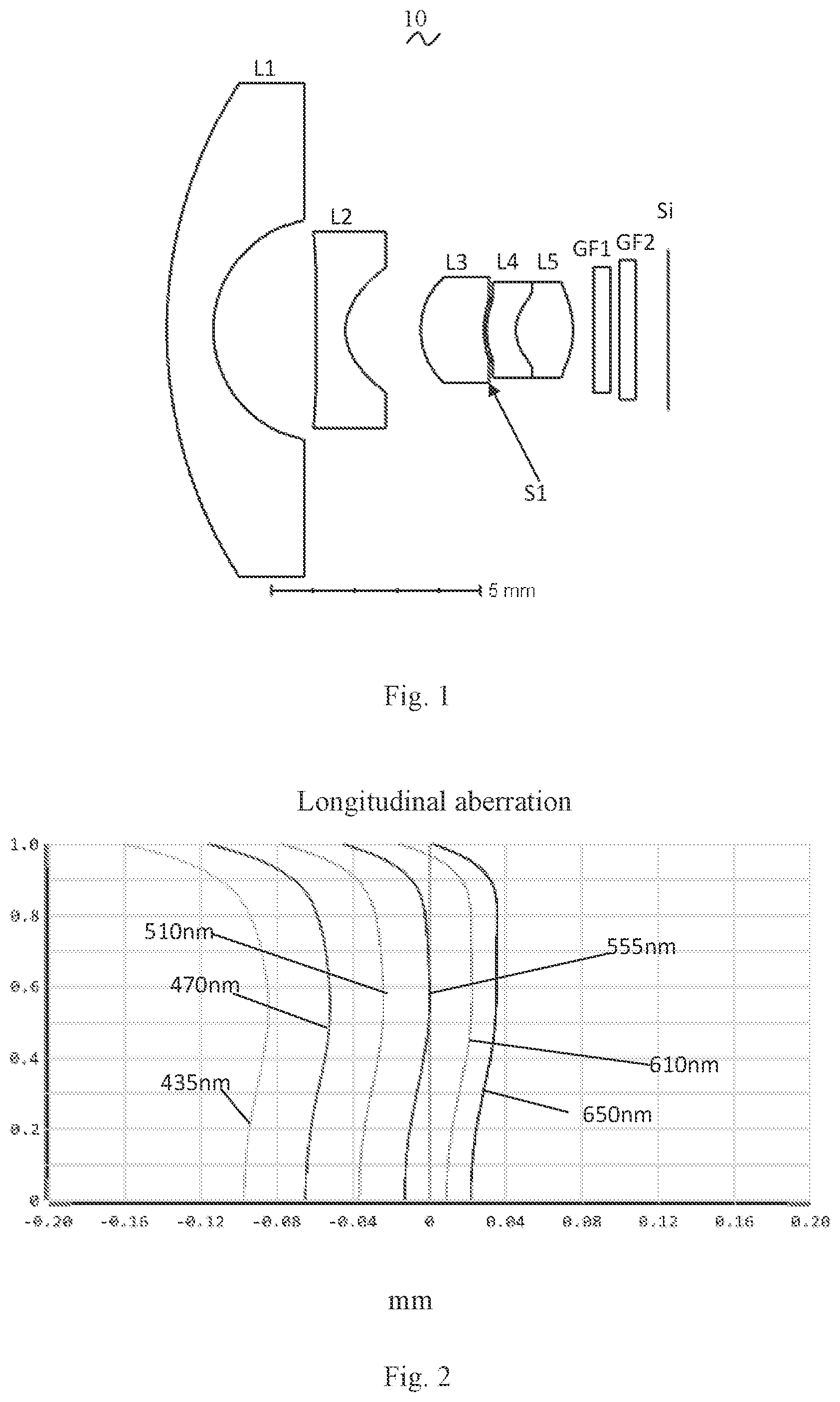
As referring to the accompanying drawings, the present invention provides a camera optical lens 10 . shows the camera optical lens 10 according to Embodiment 1 of the present invention. The camera optical lens 10 comprises five lenses. Specifically, from an object side to an image side, the camera optical lens 10 comprises in sequence: an aperture S1, a first lens L1, a second lens L2, a third lens L3, a fourth lens L4 and a fifth lens L5. Optical elements like optical filter GF can be arranged between the fifth lens L5 and an image surface S1. In this embodiment, two filters are included: GF1, GF2.
The first lens L1 is made of glass material, the second lens L2 is made of plastic material, the third lens L3 is made of glass material, the fourth lens L4 is made of plastic material and the fifth lens L5 is made of plastic material. Proper selection of glass lenses can improve the optical performance of camera optical lens. In other optional embodiments, each lens may also be made of other materials.
Object-side surfaces and image-side surfaces of the first lens L1 and the third lens L3 are spherical, and the rest of the lenses are all aspherical lenses. Designing the surfaces of some of the lenses to be spherical can reduce manufacturing difficulty.
A focal length of the camera optical lens 10 is defined as f, and a total optical length of the camera optical lens 10 is defined as TTL. The camera optical lens 10 further satisfies the following condition: 12.00≤TTL/f≤15.00, which specifies a ratio of the total optical length TTL of the camera optical lens 10 and the focal length f of the camera optical lens 10 . When the value is within this range, it benefits for realizing the ultra-thin effect.
A combined focal length of the fourth lens L4 and the fifth lens L5 is defined as f45, and the fourth lens L4 and the fifth lens L5 are cemented and connected. The camera optical lens 10 further satisfies the following condition: 2.00 f45/f 6.00, which specifies a ratio of the combined focal length f45 of the fourth lens L4 and the fifth lens L5 and the focal length f of the camera optical lens 10 . Through the reasonable distribution of focal length, the camera optical lens has better imaging quality and lower sensitivity.
A central curvature radius of the object side surface of the second lens L2 is defined as R3, and a central curvature radius of the image side surface of the second lens L2 is defined as R4. The camera optical lens 10 further satisfies the following condition: 0 (R3+R4)/(R3−R4) 1.00, which specifies a shape of the second lens L2. When the value is within this range, it can reduce a deflection of light and effectively correct a chromatism, so that the chromatism |LC|≤10 μm.
An on-axis distance from an image side surface of the second lens to an object side surface of the third lens is defined as d4, an on-axis distance from an image side surface of the third lens to an object side surface of the fourth lens is defined as d6. The camera optical lens 10 further satisfies the following condition: 8.00 d4/d6 30.00, which specifies a ratio of the on-axis distance between the second lens and the third lens and the on-axis distance between the third lens and the fifth lens. When the value is within this range, it is helpful to compress the total length of the camera optical lens and realize the ultra-thin effect.
A central curvature radius of an object side surface of the fourth lens is defined as R7, and a central curvature radius of an image side surface of the fourth lens is defined as R8. The camera optical lens 10 further satisfies the following condition: 1.50 R7/R8 8.00, a shape of the fourth lens L4. When the value is within this range, it is beneficial for correcting astigmatism and distortion of the camera optical lens, so that |Distortion|≤35.0%, and brightness or saturation can be maintained.
In the present embodiment, an object side surface of the first lens L1 is convex in a paraxial region, an image side surface of the first lens L1 is concave in the paraxial region and the first lens L1 has a negative refractive power. In other optional embodiments, the object side surface and the image side surface of the first lens L1 can also be set to other concave and convex distribution situations.
A focal length of the first lens L1 is defined as f1. The camera optical lens 10 further satisfies the following condition: −12.74 f1/f −3.46, which specifies a ratio of the focal length f1 of the first lens L1 to the focal length f of the camera optical lens 10 . When the value is within this range, it is helpful to realize ultra wide angle. Preferably, the following condition shall be satisfied, −7.97 f1/f −4.33.
A central curvature radius of an object side surface of the first lens L1 is defined as R1, and a central curvature radius of an image side surface of the first lens L1 is defined as R2. The camera optical lens 10 further satisfies the following condition: 0.78 (R1+R2)/(R1−R2) 2.77, when the value is within this range, it is helpful to realize ultra wide angle. Preferably, the following condition shall be satisfied, 1.25 (R1+R2)/(R1−R2) 2.22.
A total optical length from the object side surface of the first lens L1 to the image surface S1 of the camera optical lens 10 along an optical axis is defined as TTL. An on-axis thickness of the first lens L1 is defined as d1. The camera optical lens 10 further satisfies the following condition: 0.04 d1/TTL 0.14, which specifies a ratio of the on-axis thickness of the first lens L1 to the total optical length of the camera optical lens 10 . When the value is within this range, it benefits for realizing the ultra wide angle. Preferably, the following condition shall be satisfied, 0.06≤d1/TTL≤0.11.
In the present embodiment, the object side surface of the second lens L2 is convave in the paraxial region, the image side surface of the second lens L2 is concave in the paraxial region, and the second lens L2 has a negative refractive power. In other optional embodiments, the object side surface and the image side surface of the second lens L2 can also be set to other concave and convex distribution situations.
The focal length of the camera optical lens 10 is defined as f, and a focal length of the second lens L2 is defined as f2. The camera optical lens 10 further satisfies the following condition: −6.08 f2/f 1.43, which specifies a ratio of the focal length f2 of the second lens L2 to the focal length f of the camera optical lens 10 . When the value is within this range, it can effectively balance the field curvature of the optical system. Preferably, the following condition shall be satisfied, −3.80≤f2/f≤−1.78.
An on-axis thickness of the second lens L2 is defined as d3. The total optical length from the object side surface of the first lens L1 to the image surface S1 of the camera optical lens 10 along the optical axis is defined as TTL. The camera optical lens 10 further satisfies the following condition: 0.03 d3/TTL 0.12. When the value is within this range, it benefits for realizing the ultra-thin effect. Preferably, the following condition shall be satisfied, 0.05≤d3/TTL≤0.10.
In the present embodiment, the object side surface of the third lens L3 is convex in the paraxial region, the image side surface of the third lens L3 is concave in the paraxial region and the third lens L3 has a positive refractive power. In other optional embodiments, the object side surface and the image side surface of the third lens L3 can also be set to other concave and convex distribution situations.
The focal length of the camera optical lens 10 is defined as f, and a focal length of the third lens L3 is defined as f3. The camera optical lens 10 further satisfies the following condition: 1.50 f3/f 6.64, which specifies a ratio of the focal length of the third lens L3 to the focal length of the camera optical lens 10 . Through the reasonable distribution of optical power, the system has better imaging quality and lower sensitivity. Preferably, the following condition shall be satisfied, 2.40≤f3/f≤0.31.
The central curvature radius of the object side surface of the third lens L3 is defined as R5, and the central curvature radius of the image side surface of the third lens L3 is defined as R6. The camera optical lens 10 further satisfies the following condition: −15.66 (R5+R6)/(R5−R6) 0.21, which specifies a shape of the third lens L3. When the value is within this range, a degree of deflection of light passing through the lens can be alleviated, and the aberration can be reduced effectively. Preferably, the following condition shall be satisfied, −9.78≤(R5+R6)/(R5−R6)≤0.17.
An on-axis thickness of the third lens L3 is defined as d5. The total optical length from the object side surface of the first lens L1 to the image surface S1 of the camera optical lens 10 along the optical axis is defined as TTL. The camera optical lens 10 further satisfies the following condition: 0.05 d5/TTL 0.32, which benefits for realizing the miniaturization effect. Preferably, the following condition shall be satisfied, 0.08≤d5/TTL≤0.26.
In the present embodiment, the object side surface of the fourth lens L4 is convex in the paraxial region, the image side surface of the fourth lens L4 is concave in the paraxial region and the fourth lens L4 has a negative refractive power. In other optional embodiments, the object side surface and the image side surface of the fourth lens L4 can also be set to other concave and convex distribution situations.
The focal length of the camera optical lens 10 is defined as f, and a focal length of the fourth lens L4 is defined as f4. The camera optical lens 10 further satisfies the following condition: −19.86 f4/f 0.91. By a reasonable distribution of the refractive power, which makes it is possible that the camera optical lens 10 has an excellent imaging quality and a lower sensitivity. Preferably, the following condition shall be satisfied, −12.41≤f4/f≤−1.13.
An on-axis thickness of the fourth lens L4 is defined as d7. The total optical length from the object side surface of the first lens L1 to the image surface S1 of the camera optical lens 10 along the optical axis is defined as TTL. The camera optical lens 10 further satisfies the following condition: 0.03 d7/TTL 0.10, which benefits for realizing the miniaturization effect. Preferably, the following condition shall be satisfied, 0.05≤d7/TTL≤0.08.
In the present embodiment, the object side surface of the fifth lens L5 is convex in the paraxial region, the image side surface of the fifth lens L5 is convex in the paraxial region and the fifth lens L5 has a positive refractive power. In other optional embodiments, the object side surface and the image side surface of the fifth lens L5 can also be set to other concave and convex distribution situations.
The focal length of the camera optical lens 10 is defined as f, and a focal length of the fifth lens L5 is defined as f5. The camera optical lens 10 further satisfies the following condition: 0.60 f5/f 2.22, a light angle of the camera optical lens 10 can be smoothed effectively and the sensitivity of the tolerance can be reduced. Preferably, the following condition shall be satisfied, 0.96≤f5/f≤1.78.
The central curvature radius of the object side surface of the fifth lens L5 is defined as R9, and the central curvature radius of the image side surface of the fifth lens L5 is defined as R10. The camera optical lens further satisfies the following condition: −1.26 (R9+R10)/(R9−R10) −0.21, which specifies a shape of the fifth lens L5. When the value is within this range, as the development of the ultra-thin and telephoto lenses, it benefits for solving the problems such as correcting the off-axis aberration. Preferably, the following condition shall be satisfied, −0.79≤(R9+R10)/(R9−R10)≤−0.26.
An on-axis thickness of the fifth lens L5 is defined as d9. The total optical length from the object side surface of the first lens L1 to the image surface S1 of the camera optical lens 10 along the optical axis is defined as TTL. The camera optical lens 10 further satisfies the following condition: 0.06 d9/TTL 0.19. When the value is within this range, it benefits for realizing the miniaturization effect. Preferably, the following condition shall be satisfied, 0.09≤d9/TTL≤0.15.
In the present embodiment, a field of view of the camera optical lens 10 in a diagonal direction is defined as FOV. The FOV is greater than or equal to 190.00°, thereby achieving the wide-angle performance. Preferably, the FOV is greater than or equal to 192.00°.
In the present embodiment, an image height of the camera optical lens 10 is defined as IH. The total optical length from the object side surface of the first lens L1 to the image surface S1 of the camera optical lens 10 along an optical axis is defined as TTL. The camera optical lens 10 further satisfies the following condition: TTL/IH≤7.15, thereby achieving the miniaturization performance. Preferably, the following condition shall be satisfied, TTL/IH≤6.95.
In the present embodiment, an F number (FNO) of the camera optical lens 10 is smaller than or equal to 2.13, thereby achieving a large aperture and good imaging performance. Preferably, the FNO of the camera optical lens 10 is smaller than or equal to 2.10.
When satisfying above conditions, which makes it is possible that the camera optical lens has excellent optical performances, and meanwhile can meet design requirements of the ultra-thin, wide-angle lenses having large aperture.
According the characteristics of the camera optical lens 10 , it is particularly suitable for a mobile camera lens component and a WEB camera lens composed of high pixel CCD, CMOS.
The following examples will be used to describe the camera optical lens 10 of the present invention. The symbols recorded in each example will be described as follows. The focal length, on-axis distance, central curvature radius, on-axis thickness, inflection point position, and stationary point position are all in units of mm.
TTL: the total optical length from the object side surface of the first lens L1 to the image surface S1 of the camera optical lens 10 along the optical axis, the unit of TTL is mm.
F number (FNO): the ratio of an effective focal length of the camera optical lens 10 to an entrance pupil diameter (ENPD).
Preferably, inflection points and/or stationary points can also be arranged on the object side surface and/or image side surface of the lens, so that the demand for high quality imaging can be satisfied, the description below can be referred for specific implementable scheme.
The design information of the camera optical lens 10 in Embodiment 1 of the present invention is shown in the tables 1 and 2.
TABLE 1
R d nd vd
S1 ∞ d0= −7.742
R1 10.915 d1= 1.107 nd1 1.7246 v1 49.08
R2 2.673 d2= 2.456
R3 −243.710 d3= 0.700 nd2 1.5440 v2 55.90
R4 1.225 d4= 1.795
R5 1.700 d5= 1.516 nd3 1.7368 v3 26.66
R6 2.198 d6= 0.060
R7 1.549 d7= 0.700 nd4 1.6613 v4 76.27
R8 1.028 d8= 0.000
R9 1.028 d9= 1.363 nd5 1.5440 v5 55.90
R10 −1.969 d10= 0.500
R11 ∞ d11= 0.400 ndg1 1.5233 vg1 54.52
R12 ∞ d12= 0.200
R13 ∞ d13= 0.400 ndg2 1.5168 vg2 64.17
R14 ∞ d14= 0.773
Where, the meaning of the various symbols is as follows.
•
• S1: aperture; • R: curvature radius of an optical surface, a central curvature radius for a lens; • R1: central curvature radius of the object side surface of the first lens L1; • R2: central curvature radius of the image side surface of the first lens L1; • R3: central curvature radius of the object side surface of the second lens L2; • R4: central curvature radius of the image side surface of the second lens L2; • R5: central curvature radius of the object side surface of the third lens L3; • R6: central curvature radius of the image side surface of the third lens L3; • R7: central curvature radius of the object side surface of the fourth lens L4; • R8: central curvature radius of the image side surface of the fourth lens L4; • R9: central curvature radius of the object side surface of the fifth lens L5; • R10: central curvature radius of the image side surface of the fifth lens L5; • R11: central curvature radius of an object side surface of the optical filter GF1; • R12: central curvature radius of an image side surface of the optical filter GF1; • R11: central curvature radius of an object side surface of the optical filter GF2; • R12: central curvature radius of an image side surface of the optical filter GF2; • d: on-axis thickness of a lens and an on-axis distance between lenses; • d0: on-axis distance from the aperture S1 to the object side surface of the first lens L1; • d1: on-axis thickness of the first lens L1; • d2: on-axis distance from the image side surface of the first lens L1 to the object side surface of the second lens L2; • d3: on-axis thickness of the second lens L2; • d4: on-axis distance from the image side surface of the second lens L2 to the object side surface of the third lens L3; • d5: on-axis thickness of the third lens L3; • d6: on-axis distance from the image side surface of the third lens L3 to the object side surface of the fourth lens L4; • d7: on-axis thickness of the fourth lens L4; • d8: on-axis distance from the image side surface of the fourth lens L4 to the object side surface of the fifth lens L5; • d9: on-axis thickness of the fifth lens L5; • d10: on-axis distance from the image side surface of the fifth lens L5 to the object side surface of the optical filter GF1; • d11: on-axis thickness of the optical filter GF1; • d12: on-axis distance from the image side surface of the optical filter GF1 to the optical filter GF2; • d13: on-axis thickness of the optical filter GF2; • d14: on-axis distance from the image side surface of the optical filter GF2 to the image surface; • nd: refractive index of d line (d-line is green light with a wavelength of 550 nm); • nd1: refractive index of d line of the first lens L1; • nd2: refractive index of d line of the second lens L2; • nd3: refractive index of d line of the third lens L3; • nd4: refractive index of d line of the fourth lens L4; • nd5: refractive index of d line of the fifth lens L5; • ndg1: refractive index of d line of the optical filter GF1; • ndg2: refractive index of d line of the optical filter GF2; • vd: abbe number; • v1: abbe number of the first lens L1; • v2: abbe number of the second lens L2; • v3: abbe number of the third lens L3; • v4: abbe number of the fourth lens L4; • v5: abbe number of the fifth lens L5; • vg1: abbe number of the optical filter GF1; • vg2: abbe number of the optical filter GF2;
Table 2 shows the aspheric data of the camera optical lens 10 in Embodiment 1 of the present invention.
TABLE 2
Conic coefficient Aspheric coefficients
k A4 A6 A8 A10 A12
R3 9.0000E+01 7.4225E−03 −5.0567E−03 5.3425E−04 1.9863E−04 −5.9518E−05
R4 −8.3469E−01 4.5627E−02 −1.2312E−01 2.3638E−01 −2.8092E−01 1.7973E−01
R7 6.1592E−01 −1.1332E−01 5.9641E−02 −3.8632E−01 3.8441E−01 −1.5125E−01
R8 −8.8024E+00 1.0039E+00 −1.6537E+00 1.5821E+00 −1.3035E+00 9.6251E−01
R9 −8.8024E+00 1.0039E+00 −1.6537E+00 1.5821E+00 −1.3035E+00 9.6251E−01
R10 −3.2815E−01 4.2514E−02 −6.0786E−02 1.2775E−01 −1.5381E−01 1.0371E−01
Conic coefficient Aspheric coefficients
k A14 A16
R3 9.0000E+01 6.0128E−06 −2.3539E−07
R4 −8.3469E−01 −5.7018E−02 7.0433E−03
R7 6.1592E−01 5.7395E−02 −8.3677E−03
R8 −8.8024E+00 −6.0045E−01 1.3520E−01
R9 −8.8024E+00 −6.0045E−01 1.3520E−01
R10 −3.2815E−01 −2.8589E−02 3.1232E−03
For convenience, an aspheric surface of each lens surface uses the aspheric surfaces shown in the below condition (1). However, the present invention is not limited to the aspheric polynomials form shown in the condition (1). z =( cr 2 )/{1+[1−( k +1)( c 2 r 2 )] 1/2 }+A 4 r 4 +A 6 r 6 +A 8 r 8 +A 10 r 10 +A 12 r 12 +A 14 r 14 +A 16 r 16 (1)
Where, K is a conic coefficient, A4, A6, A8, A10, A12, A14, A16 are aspheric surface coefficients. c is the curvature at the center of the optical surface. r is a vertical distance between a point on an aspheric curve and the optic axis, and z is an aspheric depth (a vertical distance between a point on an aspheric surface, having a distance of r from the optic axis, and a surface tangent to a vertex of the aspheric surface on the optic axis).
Table 3 and Table 4 show design data of inflection points and stationary points of respective lens in the camera optical lens 10 according to Embodiment 1 of the present invention. P1R1 and P1R2 represent the object side surface and the image side surface of the first lens L1, P2R1 and P2R2 represent the object side surface and the image side surface of the second lens L2, P3R1 and P3R2 represent the object side surface and the image side surface of the third lens L3, P4R1 and P4R2 represent the object side surface and the image side surface of the fourth lens L4, and P5R1 and P5R2 represent the object side surface and the image side surface of the fifth lens L5. The data in the column named “inflection point position” refers to vertical distances from inflection points arranged on each lens surface to the optical axis of the camera optical lens 10 . The data in the column named “stationary point position” refers to vertical distances from stationary points arranged on each lens surface to the optical axis of the camera optical lens 10 .
TABLE 3
Number of Inflection Inflection
inflection point point
points position 1 position 2
P1R1 0 / /
P1R2 0 / /
P2R1 2 0.225 0.815
P2R2 0 / /
P3R1 0 / /
P3R2 0 / /
P4R1 1 0.685 /
P4R2 1 0.705 /
P5R1 1 0.705 /
P5R2 1 0.925 /
TABLE 4
Number of Stationary Stationary
stationary point point
points position 1 position 2
P1R1 0 / /
P1R2 0 / /
P2R1 2 0.405 1.035
P2R2 0 / /
P3R1 0 / /
P3R2 0 / /
P4R1 0 / /
P4R2 1 0.945 /
P5R1 1 0.945 /
P5R2 0 / /
and respectively illustrate a longitudinal aberration and a lateral color of light with wavelengths of 650 nm, 610 nm, 555 nm, 510 nm, 470 nm and 435 nm after passing the camera optical lens 10 according to Embodiment 1. illustrates a field curvature and a distortion of light with a wavelength of 555 nm after passing the camera optical lens 10 according to Embodiment 1, in which a field curvature S is a field curvature in a sagittal direction and T is a field curvature in a tangential direction.
Table 33 in the following lists values corresponding to the respective conditions. Obviously, the camera optical lens 10 of the present embodiment satisfies the above-mentioned conditions. As shown in Table 33, Embodiment 1 satisfies the above conditions.
In the present embodiment, the entrance pupil diameter (ENPD) of the camera optical lens 10 is 0.497 mm. The image height of 1.0H is 1.92 mm. The FOV is 195.60°. Thus, the camera optical lens 10 satisfies design requirements of large aperture, ultra-thin and ultra-wide-angle while the on-axis and off-axis aberrations are sufficiently corrected, thereby achieving excellent optical characteristics.
Embodiment 2
Embodiment 2 is basically the same as Embodiment 1, the meaning of its symbols is the same as that of Embodiment 1, in the following, only the differences are listed.
In this embodiment, an image side surface of a third lens L3 is convex in a paraxial region.
shows a schematic diagram of a structure of a camera optical lens 20 according to Embodiment 2 of the present invention. Table 5 and table 6 show the design data of a camera optical lens 20 in Embodiment 2 of the present invention.
TABLE 5
R d nd vd
S1 ∞ d0= −7.432
R1 9.402 d1= 1.000 nd1 1.8557 v1 41.94
R2 2.799 d2= 2.060
R3 −10.920 d3= 0.700 nd2 1.5440 v2 55.90
R4 1.213 d4= 1.500
R5 2.526 d5= 2.010 nd3 1.7913 v3 24.60
R6 −35.060 d6= 0.060
R7 1.958 d7= 0.700 nd4 1.6613 v4 76.27
R8 0.771 d8= 0.000
R9 0.771 d9= 1.417 nd5 1.5440 v5 55.90
R10 −2.307 d10= 0.500
R11 ∞ d11= 0.400 ndg1 1.5233 vg1 54.52
R12 ∞ d12= 0.300
R13 ∞ d13= 0.400 ndg2 1.5168 vg2 64.17
R14 ∞ d14= 0.404
Table 6 shows aspheric data of each lens of the camera optical lens 20 in Embodiment 2 of the present invention.
TABLE 6
Conic
coefficient Aspheric coefficients
k A4 A6 A8 A10 A12 A14 A16
R3 −5.3385E+00 2.5335E−02 −7.0095E−03 3.2252E−04 2.3630E−04 −5.9518E−05 6.0128E−06 −2.3539E−07
R4 −4.4212E+00 2.9664E−01 −2.4729E−01 2.4551E−01 −1.8543E−01 8.2815E−02 −1.8832E−02 1.6342E−03
R7 −1.0122E+00 −1.3115E−02 3.5738E−02 −1.3924E−01 2.0801E−01 −1.5125E−01 5.7395E−02 −8.3677E−03
R8 −6.9839E−01 1.1546E−01 −3.2478E−01 5.9919E−01 −8.9274E−01 9.6251E−01 −6.0045E−01 1.3520E−01
R9 −6.9839E−01 1.1546E−01 −3.2478E−01 5.9919E−01 −8.9274E−01 9.6251E−01 −6.0045E−01 1.3520E−01
R10 −1.9614E+00 4.8855E−02 −5.0578E−02 1.5968E−01 −1.8588E−01 1.0371E−01 −2.8589E−02 3.1232E−03
Table 7 and table 8 show design data of inflection points and stationary points of respective lens in the camera optical lens 20 according to Embodiment 2 of the present invention.
TABLE 7
Number of Inflection Inflection
inflection point point
points position 1 position 2
P1R1 0 / /
P1R2 0 / /
P2R1 2 0.635 1.335
P2R2 0 / /
P3R1 0 / /
P3R2 0 / /
P4R1 0 / /
P4R2 0 / /
P5R1 0 / /
P5R2 1 0.745 /
TABLE 8
Number of
stationary
points
Embodiment 2 0
and respectively illustrate a longitudinal aberration and a lateral color of light with wavelengths of 650 nm, 610 nm, 555 nm, 510 nm, 470 nm and 435 nm after passing the camera optical lens 20 according to Embodiment 2. illustrates a field curvature and a distortion of light with a wavelength of 555 nm after passing the camera optical lens 10 according to Embodiment 2, in which a field curvature S is a field curvature in a sagittal direction and T is a field curvature in a tangential direction.
Table 33 in the following lists values corresponding to the respective conditions. Obviously, the camera optical lens 20 of the present embodiment satisfies the above-mentioned conditions.
In the present embodiment, an entrance pupil diameter (ENPD) of the camera optical lens is 0.447 mm. An image height of 1.0H is 1.920 mm. Diagonal FOV is 195.60°. Thus, the camera optical lens 20 satisfies design requirements of large aperture, ultra-thin and ultra-wide-angle while the on-axis and off-axis aberrations are sufficiently corrected, thereby achieving excellent optical characteristics.
Embodiment 3
Embodiment 3 is basically the same as Embodiment 1 and involves symbols having the same meanings as Embodiment 1, and only differences will be described in the following.
In this embodiment, an image-side surface of a third lens L3 is convex in a paraxial region.
shows a schematic diagram of a structure of a camera optical lens 30 according to Embodiment 3 of the present invention. Table 9 and table 10 show the design data of the camera optical lens 30 in Embodiment 3 of the present invention.
TABLE 9
R d nd vd
S1 ∞ d0= −7.965
R1 12.342 d1= 1.000 nd1 1.6886 v1 52.10
R2 2.905 d2= 2.252
R3 −6.921 d3= 0.700 nd2 1.5440 v2 55.90
R4 1.731 d4= 2.178
R5 3.433 d5= 1.639 nd3 1.8986 v3 21.88
R6 −9.208 d6= 0.121
R7 3.223 d7= 0.700 nd4 1.6613 v4 76.27
R8 0.658 d8= 0.000
R9 0.658 d9= 1.561 nd5 1.5440 v5 55.90
R10 −2.137 d10= 0.500
R11 ∞ d11= 0.400 ndg1 1.5233 vg1 54.52
R12 ∞ d12= 0.300
R13 ∞ d13= 0.400 ndg2 1.5168 vg2 64.17
R14 ∞ d14= 0.659
Table 10 shows aspheric data of each lens of the camera optical lens 30 in Embodiment 3 of the present invention.
TABLE 10
Conic
coefficient Aspheric coefficients
k A4 A6 A8 A10 A12 A14 A16
R3 −9.0000E+01 3.2078E−02 −8.6737E−03 5.0947E−04 2.2766E−04 −5.9518E−05 6.0128E−06 −2.3539E−07
R4 −3.7431E−02 1.1550E−01 −1.5271E−01 2.1083E−01 −1.8102E−01 8.2815E−02 −1.8832E−02 1.6342E−03
R7 −4.6439E+00 −3.0140E−02 3.5109E−02 −1.0336E−01 1.7430E−01 −1.5125E−01 5.7395E−02 −8.3677E−03
R8 −6.8018E−01 −2.2182E−01 −1.4676E−01 3.8488E−01 −8.4103E−01 9.6251E−01 −6.0045E−01 1.3520E−01
R9 −6.8018E−01 −2.2182E−01 −1.4676E−01 3.8488E−01 −8.4103E−01 9.6251E−01 −6.0045E−01 1.3520E−01
R10 −1.5826E+00 3.1419E−02 −6.3135E−02 1.5606E−01 −1.7839E−01 1.0371E−01 −2.8589E−02 3.1232E−03
Table 11 and table 12 show Embodiment 3 design data of inflection points and stationary points of respective lens in the camera optical lens 30 according to Embodiment 3 of the present invention.
TABLE 11
Number of Inflection Inflection
inflection point point
points position 1 position 2
P1R1 0 / /
P1R2 0 / /
P2R1 2 0.505 1.735
P2R2 1 1.565 /
P3R1 0 / /
P3R2 0 / /
P4R1 0 / /
P4R2 0 / /
P5R1 0 / /
P5R2 1 0.995 /
TABLE 12
Number of Stationary Stationary
stationary point point
points position 1 position 2
P2R1 2 1.025 2.505
and respectively illustrate a longitudinal aberration and a lateral color of light with wavelengths of 650 nm, 610 nm, 555 nm, 510 nm, 470 nm and 435 nm after passing the camera optical lens 30 according to Embodiment 3. illustrates a field curvature and a distortion of light with a wavelength of 555 nm after passing the camera optical lens 30 according to Embodiment 3, in which a field curvature S is a field curvature in a sagittal direction and T is a field curvature in a tangential direction.
Table 33 in the following lists values corresponding to the respective conditions. Obviously, the camera optical lens 30 of the present embodiment satisfies the above-mentioned conditions.
In the present embodiment, an entrance pupil diameter (ENPD) of the camera optical lens is 0.46 mm. An image height of 1.0H is 1.920 mm. A diagonal FOV is 195.60°. Thus, the camera optical lens 30 satisfies design requirements of large aperture, ultra-thin and ultra-wide-angle while the on-axis and off-axis aberrations are sufficiently corrected, thereby achieving excellent optical characteristics.
Embodiment 4
Embodiment 4 is basically the same as Embodiment 1 and involves symbols having the same meanings as Embodiment 1, and only differences therebetween will be described in the following.
In this embodiment, an image side surface of a third lens L3 is convex in a paraxial region.
shows a schematic diagram of a structure of a camera optical lens 40 according to Embodiment 4 of the present invention. A third lens L3 has a positive refractive power. The third lens L3 has an object side surface being convex in a paraxial position, and an image side surface being concave in the paraxial position. Tables 13 and 14 show the design data of a camera optical lens 40 in Embodiment 4 of the present invention.
TABLE 13
R d nd vd
S1 ∞ d0= −8.296
R1 12.711 d1= 1.000 nd1 1.7175 v1 49.62
R2 3.008 d2= 2.352
R3 −4.704 d3= 0.861 nd2 1.5440 v2 55.90
R4 2.016 d4= 2.463
R5 3.368 d5= 1.656 nd3 1.8887 v3 24.74
R6 −6.648 d6= 0.205
R7 4.166 d7= 0.733 nd4 1.6613 v4 76.27
R8 0.636 d8= 0.000
R9 0.636 d9= 1.681 nd5 1.5440 v5 55.90
R10 −2.166 d10= 0.500
R11 ∞ d11= 0.400 ndg1 1.5233 vg1 54.52
R12 ∞ d12= 0.300
R13 ∞ d13= 0.400 ndg2 1.5168 vg2 64.17
R14 ∞ d14= 0.531
Table 14 shows aspheric data of each lens of the camera optical lens 40 in Embodiment 4 of the present invention.
TABLE 14
Conic
coefficient Aspheric coefficients
k A4 A6 A8 A10 A12 A14 A16
R3 −9.0000E+01 3.2182E−02 −8.1052E−03 4.0479E−04 2.3396E−04 −5.9518E−05 6.0128E−06 −2.3539E−07
R4 3.6190E−01 1.5621E−01 −1.9030E−01 2.2794E−01 −1.8374E−01 8.2815E−02 −1.8832E−02 1.6342E−03
R7 −9.7521E−01 −5.7188E−02 4.9728E−02 −1.2366E−01 1.8877E−01 −1.5125E−01 5.7395E−02 −8.3677E−03
R8 −7.4890E−01 −2.9034E−01 6.9228E−02 1.2308E−01 −6.8529E−01 9.6251E−01 −6.0045E−01 1.3520E−01
R9 −7.4890E−01 −2.9034E−01 6.9228E−02 1.2308E−01 −6.8529E−01 9.6251E−01 −6.0045E−01 1.3520E−01
R10 −2.1875E+00 3.8298E−02 −1.0043E−01 1.8856E−01 −1.8975E−01 1.0371E−01 −2.8589E−02 3.1232E−03
Table 15 and table 16 show Embodiment 4 design data of inflection points and stationary points of respective lens in the camera optical lens 40 according to Embodiment 4 of the present invention.
TABLE 15
Number of Inflection Inflection
inflection point point
points position 1 position 2
P1R1 0 / /
P1R2 0 / /
P2R1 2 0.495 2.035
P2R2 0 / /
P3R1 0 / /
P3R2 0 / /
P4R1 1 0.695
P4R2 0 / /
P5R1 0 / /
P5R2 1 1.125 /
TABLE 16
Number of Stationary Stationary
stationary point point
points position 1 position 2
P2R1 2 1.065 2.665
and respectively illustrate a longitudinal aberration and a lateral color of light with wavelengths of 650 nm, 610 nm, 555 nm, 510 nm, 470 nm and 435 nm after passing the camera optical lens 30 according to Embodiment 4. illustrates a field curvature and a distortion of light with a wavelength of 555 nm after passing the camera optical lens 40 according to Embodiment 4, in which a field curvature S is a field curvature in a sagittal direction and T is a field curvature in a tangential direction.
Table 33 in the following lists values corresponding to the respective conditions. Obviously, the camera optical lens 40 of the present embodiment satisfies the above-mentioned conditions.
In the present embodiment, an entrance pupil diameter (ENPD) of the camera optical lens is 0.437 mm. An image height of 1.0H is 1.920 mm. An FOV is 195.60°. Thus, the camera optical lens 40 satisfies design requirements of large aperture, ultra-thin and ultra-wide-angle while the on-axis and off-axis aberrations are sufficiently corrected, thereby achieving excellent optical characteristics.
Embodiment 5
Embodiment 5 is basically the same as Embodiment 1 and involves symbols having the same meanings as Embodiment 1, and only differences therebetween will be described in the following.
An image side surface of a third lens L3 is convex in a paraxial region.
shows a schematic diagram of a structure of a camera optical lens 50 according to Embodiment 5 of the present invention. Tables 17 and 18 show the design data of a camera optical lens 50 in Embodiment 5 of the present invention.
TABLE 17
R d nd vd
S1 ∞ d0= −8.233
R1 13.464 d1= 1.000 nd1 1.7125 v1 50.02
R2 2.941 d2= 2.315
R3 −3.060 d3= 1.042 nd2 1.5440 v2 55.90
R4 2.999 d4= 2.677
R5 3.339 d5= 1.247 nd3 1.8697 v3 29.90
R6 −6.530 d6= 0.334
R7 3.446 d7= 0.815 nd4 1.6613 v4 76.27
R8 0.626 d8= 0.000
R9 0.626 d9= 1.645 nd5 1.5440 v5 55.90
R10 −2.746 d10= 0.500
R11 ∞ d11= 0.400 ndg1 1.5233 vg1 54.52
R12 ∞ d12= 0.300
R13 ∞ d13= 0.400 ndg2 1.5168 vg2 64.17
R14 ∞ d14= 0.199
Table 18 shows aspheric data of each lens of the camera optical lens 50 in Embodiment 5 of the present invention.
TABLE 18
Conic
coefficient Aspheric coefficients
k A4 A6 A8 A10 A12 A14 A16
R3 −4.7071E+01 3.0611E−02 −6.6133E−03 1.9298E−04 2.4398E−04 −5.9518E−05 6.0128E−06 −2.3539E−07
R4 2.1906E+00 1.9822E−01 −2.2371E−01 2.4851E−01 −1.8754E−01 8.2815E−02 −1.8832E−02 1.6342E−03
R7 2.4244E−01 −5.3074E−02 4.8626E−02 −1.2358E−01 1.8772E−01 −1.5125E−01 5.7395E−02 −8.3677E−03
R8 −7.5973E−01 −2.3356E−01 6.7644E−02 1.3177E−01 −6.8367E−01 9.6251E−01 −6.0045E−01 1.3520E−01
R9 −7.5973E−01 −2.3356E−01 6.7644E−02 1.3177E−01 −6.8367E−01 9.6251E−01 −6.0045E−01 1.3520E−01
R10 −7.2671E+00 4.7968E−02 −1.1986E−01 2.1027E−01 −1.9767E−01 1.0371E−01 −2.8589E−02 3.1232E−03
Table 19 and table 20 show Embodiment 5 design data of inflection points and stationary points of respective lens in the camera optical lens 50 according to Embodiment 5 of the present invention.
TABLE 19
Number of Inflection Inflection
inflection point point
points position 1 position 2
P1R1 0 / /
P1R2 0 / /
P2R1 2 0.535 2.455
P2R2 0 / /
P3R1 0 / /
P3R2 0 / /
P4R1 1 0.825 /
P4R2 0 / /
P5R1 0 / /
P5R2 2 0.885 1.165
TABLE 20
Number of Stationary
stationary point
points position 1
P2R1 1 1.255
and respectively illustrate a longitudinal aberration and a lateral color of light with wavelengths of 650 nm, 610 nm, 555 nm, 510 nm, 470 nm and 435 nm after passing the camera optical lens 50 according to Embodiment 5. illustrates a field curvature and a distortion of light with a wavelength of 555 nm after passing the camera optical lens 50 according to Embodiment 5, in which a field curvature S is a field curvature in a sagittal direction and T is a field curvature in a tangential direction.
Table 33 in the following lists values corresponding to the respective conditions. Obviously, the camera optical lens 50 of the present embodiment satisfies the above-mentioned conditions.
In the present embodiment, an entrance pupil diameter (ENPD) of the camera optical lens is 0.417 mm. An image height of 1.0H is 1.920 mm. An diagonal FOV is 195.60°. Thus, the camera optical lens 50 satisfies design requirements of large apertures, ultra-thin and wide-angle.
Embodiment 6
Embodiment 6 is basically the same as Embodiment 1 and involves symbols having the same meanings as Embodiment 1, and only differences therebetween will be described in the following.
An image side surface of a third lens L3 is convex in a paraxial region.
shows a schematic diagram of a structure of a camera optical lens 50 according to Embodiment 5 of the present invention. Tables 21 and 22 show the design data of a camera optical lens 60 in Embodiment 6 of the present invention.
TABLE 21
R d nd vd
S1 ∞ d0= −7.975
R1 10.970 d1= 1.000 nd1 1.8040 v1 46.57
R2 2.927 d2= 2.177
R3 −2.884 d3= 0.894 nd2 1.5444 v2 56.43
R4 2.424 d4= 1.019
R5 6.359 d5= 2.758 nd3 1.9229 v3 20.88
R6 −4.784 d6= 0.070
R7 3.052 d7= 0.842 nd4 1.6613 v4 76.80
R8 0.746 d8= 0.000
R9 0.746 d9= 1.659 nd5 1.5444 v5 56.43
R10 −1.823 d10= 0.500
R11 ∞ d11= 0.400 ndg1 1.5233 vg1 54.52
R12 ∞ d12= 0.500
R13 ∞ d13= 0.400 ndg2 1.5168 vg2 64.17
R14 ∞ d14= 0.601
Table 22 shows aspheric data of each lens of the camera optical lens 60 in Embodiment 6 of the present invention.
TABLE 18
Conic
coefficient Aspheric coefficients
k A4 A6 A8 A10 A12 A14 A16
R3 −2.6361E+01 3.9879E−02 −1.5349E−02 3.6604E−03 −5.9678E−04 6.3199E−05 −3.7941E−06 9.0933E−08
R4 6.8710E−01 1.7532E−01 −1.3827E−01 1.3839E−01 −1.1542E−01 5.8198E−02 −1.5011E−02 1.4686E−03
R7 −6.2438E+00 −1.1484E−02 1.9383E−01 −1.3403E+00 4.9301E+00 −9.8740E+00 1.0084E+01 −4.0882E+00
R8 −6.1996E−01 −1.8632E−01 6.9675E−02 −6.6477E−01 1.5033E+00 −1.8591E+00 1.1943E+00 −3.3261E−01
R9 −6.1996E−01 −1.8632E−01 6.9675E−02 −6.6477E−01 1.5033E+00 −1.8591E+00 1.1943E+00 −3.3261E−01
R10 −1.6836E+00 4.9032E−02 −1.9371E−01 4.9821E−01 −7.0544E−01 5.7102E−01 −2.4482E−01 4.3333E−02
Table 23 and table 24 show Embodiment 6 design data of inflection points and stationary points of respective lens in the camera optical lens 60 according to Embodiment 6 of the present invention.
TABLE 23
Number of Inflection Inflection
inflection point point
points position 1 position 2
P1R1 0 / /
P1R2 0 / /
P2R1 2 0.595 1.905
P2R2 1 1.475 /
P3R1 0 / /
P3R2 0 / /
P4R1 0 / /
P4R2 1 0.915 /
P5R1 1 0.915 /
P5R2 1 1.005 /
TABLE 24
Number of
stationary
points
Embodiment 6 0
and respectively illustrate a longitudinal aberration and a lateral color of light with wavelengths of 650 nm, 610 nm, 555 nm, 510 nm, 470 nm and 435 nm after passing the camera optical lens 60 according to Embodiment 6. illustrates a field curvature and a distortion of light with a wavelength of 555 nm after passing the camera optical lens 60 according to Embodiment 6, in which a field curvature S is a field curvature in a sagittal direction and T is a field curvature in a tangential direction.
Table 33 in the following lists values corresponding to the respective conditions. Obviously, the camera optical lens 60 of the present embodiment satisfies the above-mentioned conditions.
In the present embodiment, an entrance pupil diameter (ENPD) of the camera optical lens is 0.455 mm. An image height of 1.0H is 1.920 mm. An diagonal FOV is 194.40°. Thus, the camera optical lens 50 satisfies design requirements of large apertures, ultra-thin and wide-angle and has excellent optical performance.
Embodiment 7
Embodiment 7 is basically the same as Embodiment 1 and involves symbols having the same meanings as Embodiment 1, and only differences therebetween will be described in the following.
An image side surface of a third lens L3 is convex in a paraxial region.
shows a schematic diagram of a structure of a camera optical lens 50 according to Embodiment 7 of the present invention. Tables 25 and 26 show the design data of a camera optical lens 70 in Embodiment 7 of the present invention.
TABLE 25
R d nd vd
S1 ∞ d0= −8.084
R1 10.970 d1= 1.000 nd1 1.8040 v1 46.57
R2 2.927 d2= 2.097
R3 −3.271 d3= 0.777 nd2 1.5365 v2 55.98
R4 2.224 d4= 1.315
R5 6.359 d5= 2.758 nd3 1.9229 v3 20.88
R6 −4.784 d6= 0.066
R7 3.119 d7= 0.822 nd4 1.6613 v4 76.36
R8 0.709 d8= 0.000
R9 0.709 d9= 1.632 nd5 1.5365 v5 55.98
R10 −1.835 d10= 0.500
R11 ∞ d11= 0.400 ndg1 1.5233 vg1 54.52
R12 ∞ d12= 0.300
R13 ∞ d13= 0.400 ndg2 1.5168 vg2 64.17
R14 ∞ d14= 0.851
Table 26 shows aspheric data of each lens of the camera optical lens 70 in Embodiment 7 of the present invention.
TABLE 26
Conic
coefficient Aspheric coefficients
k A4 A6 A8 A10 A12 A14 A16
R3 −4.4987E+01 3.3895E−02 −8.5162E−03 4.2888E−04 2.3341E−04 −5.9518E−05 6.0128E−06 −2.3539E−07
R4 5.7908E−01 1.8728E−01 −1.9530E−01 2.2924E−01 −1.8399E−01 8.2815E−02 −1.8832E−02 1.6342E−03
R7 −3.8065E+00 −2.7585E−02 5.6153E−02 −1.4190E−01 2.0033E−01 −1.5125E−01 5.7395E−02 −8.3677E−03
R8 −6.2768E−01 −2.2255E−01 −1.4640E−01 3.4768E−01 −8.1532E−01 9.6251E−01 −6.0045E−01 1.3520E−01
R9 −6.2768E−01 −2.2255E−01 −1.4640E−01 3.4768E−01 −8.1532E−01 9.6251E−01 −6.0045E−01 1.3520E−01
R10 −3.1698E+00 8.9559E−04 −8.3883E−02 1.8214E−01 −1.8635E−01 1.0371E−01 −2.8589E−02 3.1232E−03
Table 27 and table 28 show Embodiment 7 design data of inflection points and stationary points of respective lens in the camera optical lens 70 according to Embodiment 7 of the present invention.
TABLE 27
Number of Inflection Inflection
inflection point point
points position 1 position 2
P1R1 0 / /
P1R2 0 / /
P2R1 2 0.535 1.845
P2R2 1 1.525
P3R1 0 / /
P3R2 0 / /
P4R1 0 / /
P4R2 1 0.935 /
P5R1 1 0.935 /
P5R2 1 1.045 /
TABLE 28
Number of Stationary Stationary
stationary point point
points position 1 position 2
P2R1 2 1.275 2.435
and respectively illustrate a longitudinal aberration and a lateral color of light with wavelengths of 650 nm, 610 nm, 555 nm, 510 nm, 470 nm and 435 nm after passing the camera optical lens 70 according to Embodiment 7. illustrates a field curvature and a distortion of light with a wavelength of 555 nm after passing the camera optical lens 70 according to Embodiment 7, in which a field curvature S is a field curvature in a sagittal direction and T is a field curvature in a tangential direction.
Table 33 in the following lists values corresponding to the respective conditions. Obviously, the camera optical lens 70 of the present embodiment satisfies the above-mentioned conditions.
In the present embodiment, an entrance pupil diameter (ENPD) of the camera optical lens is 0.455 mm. An image height of 1.0H is 1.920 mm. An diagonal FOV is 195.20°. Thus, the camera optical lens 50 satisfies design requirements of large apertures, ultra-thin and wide-angle, and has excellent optical performance.
Comparative Embodiment
Comparative Embodiment is basically the same as Embodiment 1 and involves symbols having the same meanings as Embodiment 1, and only differences therebetween will be described in the following.
shows a schematic diagram of a structure of a camera optical lens 80 according to Comparative Embodiment. Tables 29 and 30 show the design data of a camera optical lens 80 in Comparative Embodiment.
TABLE 29
R d nd vd
S1 ∞ d0= −7.696
R1 12.964 d1= 1.000 nd1 1.7125 v1 50.02
R2 2.801 d2= 2.606
R3 −2.542 d3= 1.272 nd2 1.5440 v2 55.90
R4 2.491 d4= 1.894
R5 3.928 d5= 1.000 nd3 1.8697 v3 29.90
R6 −3.629 d6= 0.095
R7 5.109 d7= 1.113 nd4 1.6613 v4 76.27
R8 0.653 d8= 0.000
R9 0.653 d9= 1.496 nd5 1.5440 v5 55.90
R10 −2.048 d10= 0.500
R11 ∞ d11= 0.400 ndg1 1.5233 vg1 54.52
R12 ∞ d12= 0.300
R13 ∞ d13= 0.400 ndg2 1.5168 vg2 64.17
R14 ∞ d14= 0.300
Table 30 shows aspheric data of each lens of the camera optical lens 80 in Comparative Embodiment of the present invention.
TABLE 30
Conic
coefficient Aspheric coefficients
k A4 A6 A8 A10 A12 A14 A16
R3 −5.0371E+01 3.0806E−02 −6.6726E−03 1.8962E−04 2.4439E−04 −5.9518E−05 6.0128E−06 −2.3539E−07
R4 2.2483E+00 2.0332E−01 −2.2890E−01 2.5159E−01 −1.8828E−01 8.2815E−02 −1.8832E−02 1.6342E−03
R7 −5.5655E−01 −4.4396E−02 4.0147E−02 −1.0594E−01 1.7518E−01 −1.5125E−01 5.7395E−02 −8.3677E−03
R8 −7.5239E−01 −1.9465E−01 −7.0878E−04 2.2385E−01 −7.2858E−01 9.6251E−01 −6.0045E−01 1.3520E−01
R9 −7.5239E−01 −1.9465E−01 −7.0878E−04 2.2385E−01 −7.2858E−01 9.6251E−01 −6.0045E−01 1.3520E−01
R10 −5.7875E+00 6.3848E−02 −1.2903E−01 2.2197E−01 −2.0292E−01 1.0371E−01 −2.8589E−02 3.1232E−03
Table 31 and table 32 show Comparative Embodiment design data of inflection points and stationary points of respective lens in the camera optical lens 80 according to Comparative Embodiment of the present invention.
TABLE 31
Number of Inflection Inflection
inflection point point
points position 1 position 2
P1R1 0 / /
P1R2 0 / /
P2R1 2 0.505 2.395
P2R2 0 / /
P3R1 0 / /
P3R2 0 / /
P4R1 1 0.715 /
P4R2 1 1.025 /
P5R1 1 1.025 /
P5R2 2 0.775 1.115
TABLE 32
Number of Stationary
stationary point
points position 1
P2R1 1 1.245
and respectively illustrate a longitudinal aberration and a lateral color of light with wavelengths of 650 nm, 610 nm, 555 nm, 510 nm, 470 nm and 435 nm after passing the camera optical lens 80 according to Comparative Embodiment. illustrates a field curvature and a distortion of light with a wavelength of 555 nm after passing the camera optical lens 80 according to Comparative Embodiment, in which a field curvature S is a field curvature in a sagittal direction and T is a field curvature in a tangential direction.
Table 33 in the following lists values corresponding to the respective conditions. The camera optical lens 80 according to Comparative Embodiment does not satisfy the above condition 12.00≤TTL/f≤15.00.
In the present embodiment, an entrance pupil diameter (ENPD) of the camera optical lens 80 is 0.390 mm. An image height of 1.0H is 1.920 mm. An diagonal FOV is 196.40°. Thus, the camera optical lens 80 does not satisfy design requirements of large aperture, ultra-thin and wide-angle. The on-axis and off-axis chromatic aberrations are not sufficiently corrected.
TABLE 33
Parameters and Comparative
conditions Embodiment 1 Embodiment 2 Embodiment 3 Embodiment 4 Embodiment 5 Embodiment
TTL/f 12.042 12.501 12.995 14.503 14.970 13.755
(R3 + R4)/(R3 − R4) 0.990 0.800 0.600 0.400 0.010 0.087
f45/f 2.099 2.999 3.998 5.002 5.989 3.387
d4/d6 29.917 25.000 18.000 12.015 8.015 14.557
R7/R8 1.507 2.540 4.898 6.550 5.505 4.091
f 0.994 0.916 0.955 0.902 0.860 0.932
f1 −5.159 −4.988 −5.746 −5.719 −5.480 −5.238
f2 −2.231 −1.961 −2.466 −2.474 −2.616 −2.276
f3 4.402 3.028 2.942 2.709 2.683 3.330
f4 −9.872 −2.497 −1.392 −1.226 −1.296 −1.732
f5 1.474 1.265 1.149 1.142 1.128 1.256
FNO 2.001 2.051 2.075 2.064 2.065 2.048
TTL 11.970 11.451 12.410 13.082 12.874 12.820
IH 1.920 1.920 1.920 1.920 1.920 1.920
FOV 195.60 195.60 195.60 195.60 195.60 194.40
It is to be understood, however, that even though numerous characteristics and advantages of the present exemplary embodiments have been set forth in the foregoing description, together with details of the structures and functions of the embodiments, the disclosure is illustrative only, and changes may be made in detail, especially in matters of shape, size, and arrangement of parts within the principles of the invention to the full extent indicated by the broad general meaning of the terms where the appended claims are expressed.
Figures (16)
Citations
This patent cites (13)
- US2009/0052057
- US2010/0188757
- US2010/0254025
- US2011/0102541
- US2012/0275037
- US2014/0204478
- US2015/0116569
- US2015/0185445
- US2017/0010446
- US2017/0184812
- US2018/0017766
- US2019/0094492
- US2020/0081229