Abstract
The present invention relates to a field of optical lens, and discloses a camera lens with six-piece lenses including a first lens having a positive refractive power, a second lens having a negative refractive power, a third lens, a fourth lens having a positive refractive power, a fifth lens, and a sixth lens having a negative refractive power. The camera lens satisfies following conditions: in an imaging status TTL/LB≤2.40, 0.20≤R1/R2≤0.35, 0.20≤R1/R2≤0.35, 0.02≤d5/f≤0.04, and −0.90≤f2/f≤−0.70. The present invention has a small height in a retraction status, and a narrow angle as well as good optical properties in the imaging status.
Claims (3)
1. A camera lens with six-piece lens, comprising, from an object side to an image side in sequence: a first lens having a positive refractive power, a second lens having a negative refractive power, a third lens, a fourth lens having a positive refractive power, a fifth lens, and a sixth lens having a negative refractive power, and the camera lens satisfies following conditions: in an imaging status, TTL/LB≤2.40; 0.20≤R1/R2≤0.35; 0.02≤d5/f≤0.04; −0.90≤f2/f≤−0.70; and 0.10≤R7/R8≤0.55, where TTL denotes an on-axis distance from an object side surface of the first lens to an image surface of the camera lens along an optical axis, LB denotes a back focal length of the camera lens, R1 denotes a central curvature radius of the object side surface of the first lens, R2 denotes a central curvature radius of an image side surface of the first lens, d5 denotes a center thickness of the third lens, f denotes a focal length of the camera lens, f2 denotes a focal length of the second lens, R7 denotes a central curvature radius of an object side surface of the fourth lens, and R8 denotes a central curvature radius of an image side surface of the fourth lens.
Show 2 dependent claims
2. The camera lens according to claim 1 , wherein, the camera lens further satisfies a following condition: 0.29≤DL36/TTL (in the imaging status)≤0.33, where DL36 denotes an on-axis distance from an object side surface of the third lens to an image side surface of the sixth lens.
3. The camera lens according to claim 1 , wherein, the camera lens further satisfies a following condition: 0.52≤f1/f≤0.58, where f1 denotes a focal length of the first lens.
Full Description
Show full text →
FIELD OF THE PRESENT INVENTION
The present invention relates to a camera lens, and more particularly, to an invention of a camera lens suitable for camera assemblies, digital cameras, or the like for smartphones, which adopt camera elements such as CCDs and CMOS for high pixels. The camera lens in the invention is a camera lens in an imaging status with a narrow angle of 50° or less at full viewing angle (hereinafter referred as 2ω) and having good optical properties, while in a retraction status, the camera lens has a TTL/IH of 1.50 or less, and involves a small height in the retraction status. The camera lens consists of six-piece lenses.
DESCRIPTION OF RELATED ART
As in the camera lens, the TTL (total optical length of the camera lens) becomes longer and the field of view gets narrower, in recent years such a camera lens is needed that: the camera lens could possess a narrow angle and good optical properties in the imaging status, while in the retraction status the lens barrel could be contracted into the camera for obtaining a shorter TTL and a lower height during retraction.
There is a technology development of a camera lens is being promoted, the camera lens consisting of six-piece lenses and including a narrow angle and good optical properties. As a camera lens of a six-piece lenses structure, the camera lens in a related art consists of six-piece lenses, including from an object side to an image side in sequence: a first lens with a positive refractive power, a second lens with a negative refractive power, a third lens with a negative refractive power, a fourth lens with a positive refractive power, a fifth lens with a negative refractive power, and a sixth lens with a negative refractive power.
Although the 2ω of the camera lens the related art is narrowed to 46.6° or less, the ratio of TTL in the imaging status to LB in the imaging status is still not sufficient, and therefore the height in the retraction status is also not reduced sufficiently.
SUMMARY
In the present invention, a camera lens is provided. The camera lens has a small height in a retraction status, while in an imaging status, the camera lens could have a narrow angle and good optical properties, and the camera lens consists of six-piece lenses.
Inventors of the present invention carefully studied a ratio of TTL to LB (back focus length) in the imaging status, a ratio of a central curvature radius of an object side surface of a first lens to a central curvature radius of an image side surface of the first lens, a ratio of a center thickness of a third lens to a focal length of the whole camera lens, and a ratio of a focal length of a second lens to the focal length of the whole camera lens, it was found that a camera lens that can resolve the problems of the related art could be obtained, and the present invention is thus acquired.
According to one aspect of the present invention, a camera lens with six-piece lens is provided, comprising, from an object side to an image side in sequence: a first lens having a positive refractive power, a second lens having a negative refractive power, a third lens, a fourth lens having a positive refractive power, a fifth lens, and a sixth lens having a negative refractive power; and the camera lens satisfies the following conditions: in a imaging status, TTL/LB≤2.40, 0.20≤R1/R2≤0.35, 0.02 d5/f≤0.04, and −0.90≤f2/≤f≤−0.70. TTL denotes a total optical length (an on-axis distance from an object side surface of the first lens to an image surface of the camera lens along an optical axis), LB denotes a back focal length of the camera lens, R1 denotes a central curvature radius of the object side surface of the first lens, R2 denotes a central curvature radius of an image side surface of the first lens, d5 denotes a center thickness of the third lens, f denotes a focal length of the camera lens, and f2 denotes a focal length of the second lens.
As an improvement, the camera lens further satisfies a following condition: 0.29≤DL36/TTL(in the imaging status) 0.33, where DL36 denotes an on-axis distance from an object side surface of the third lens to an image side surface of the sixth lens.
As an improvement, the camera lens further satisfies a following condition: 0.10≤R7/R8≤0.55, where R7 denotes a central curvature radius of an object side surface of the fourth lens, and R8 denotes a central curvature radius of an image side surface of the fourth lens.
As an improvement, the camera lens further satisfies a following condition: 0.52≤f1/f≤0.58, where f denotes the focal length of the camera lens, and f1 denotes a focal length of the first lens.
Beneficial effects of the present invention are that: according to the present invention, a camera lens is particularly related, which is suitable for camera assemblies, digital cameras, or the like, for smartphones, which adopt camera elements such as CCDs and CMOS for high pixels. The camera lens in the invention, in an imaging status is a camera lens, with a narrow angle 2ω≤50° and having good optical properties, while in a retraction status, TTL/IH≤1.50, and a small height in the retraction status is obtained, and the camera lens consists of six-piece lenses.
BRIEF DESCRIPTION OF THE DRAWINGS
In order to explain the technical solutions in the embodiments of the present invention more clearly, the following will briefly introduce the drawings that need to be used in the description of the embodiments. Obviously, the drawings in the following description are only some embodiments of the present invention. For those of ordinary skill in the art, without creative efforts, other drawings can be obtained based on these drawings, among which:
is a schematic diagram of a general structure of a camera lens in accordance with Embodiment 1 of the present invention;
is a schematic diagram of a longitudinal aberration, an astigmatism field curvature and a distortion of the camera lens shown in ;
is a schematic diagram of a general structure of a camera lens in accordance with Embodiment 2 of the present invention;
is a schematic diagram of a longitudinal aberration, an astigmatism field curvature and a distortion of the camera lens shown in ;
is a schematic diagram of a general structure of a camera lens in accordance with Embodiment 3 of the present invention;
is a schematic diagram of a longitudinal aberration, an astigmatism field curvature and a distortion of the camera lens shown in .
is a schematic diagram of a general structure of a camera lens in accordance with Embodiment 4 of the present invention;
is a schematic diagram of a longitudinal aberration, an astigmatism field curvature and a distortion of the camera lens shown in .
DETAILED DESCRIPTION OF THE EXEMPLARY EMBODIMENTS
The present invention is further illustrated with reference to the accompanying drawings and embodiments. To make the objects, technical solutions, and advantages of the present disclosure clearer, the embodiments of the present invention are described in detail with reference to the accompanying drawings below. A person of ordinary skill in the related art can understand that, in the embodiments of the present disclosure, many technical details are provided to make readers better understand this application. However, even without these technical details and any changes and modifications based on the following embodiments, technical solutions required to be protected by this application can be implemented.
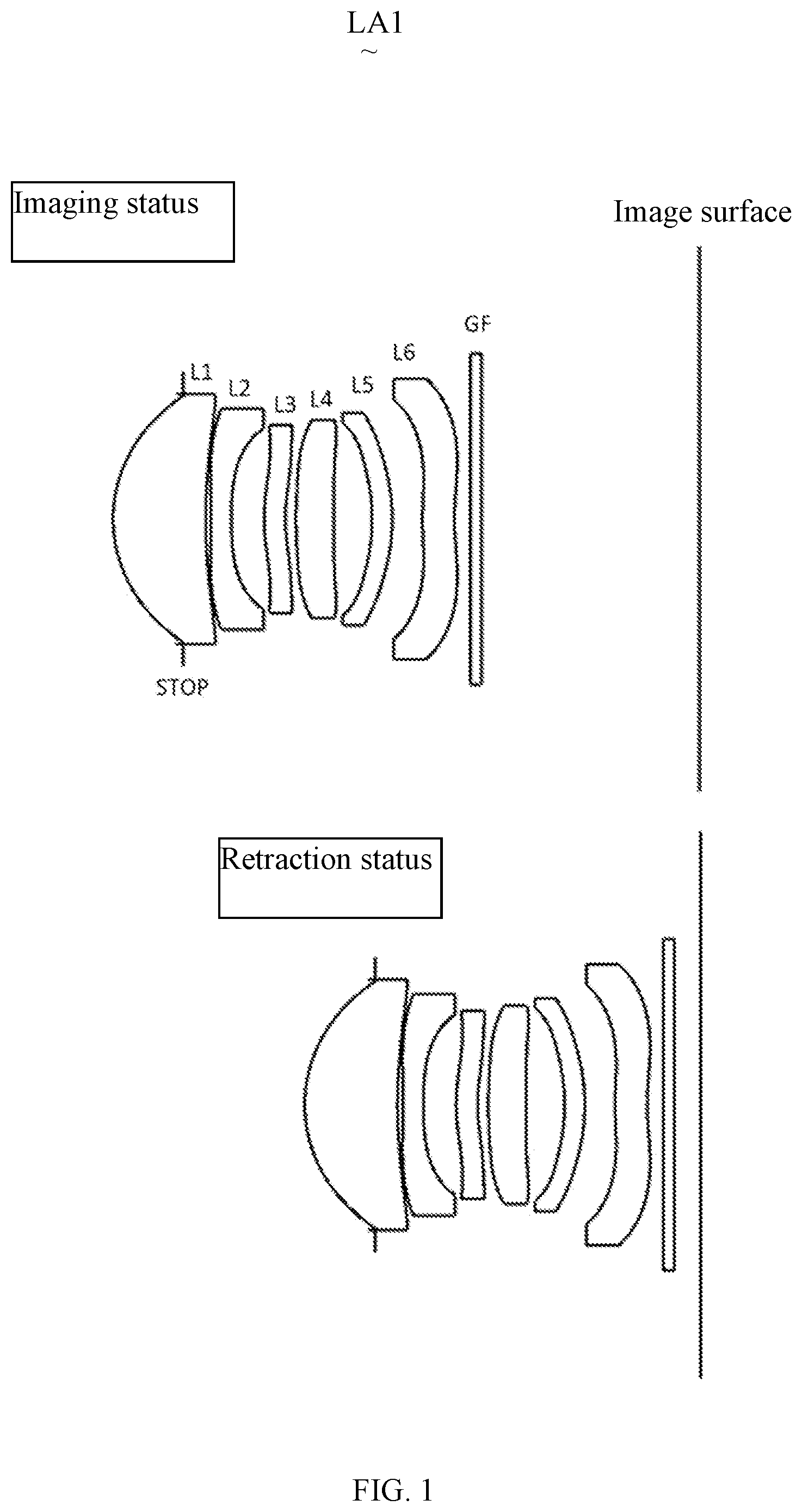
Embodiments of the camera lens in the present invention are described below. The camera lens LA 1 has lens system of a six-piece lens structure. The six-piece lens structure, includes from an object side to an image side in sequence, a first lens L 1 , a second lens L 2 , a third lens L 3 , a fourth lens L 4 , a fifth lens L 5 , and a sixth lens L 6 . A glass plate GF is provided between the sixth lens L 6 and an image surface. The glass plate GF can be a glass cover plate or an optical filter. In the present invention, the glass plate GF can be provided at different positions, or can be omitted.
The first lens L 1 has a positive refractive power, the second lens L 2 has a negative refractive power, the third lens L 3 has a positive or negative refractive power, the fourth lens L 4 has a positive refractive power, the fifth lens L 5 has a positive or negative refractive power, and the sixth lens L 6 has a negative refractive power. In order to correct various aberrations, it is desirable to design all surfaces of these six-piece lenses as aspherical surfaces.
The camera lens LA 1 satisfies a following condition (1): in an imaging status, TTL/LB≤ 2.40 (1)
The condition (1) specifies a ratio of a total optical length (an on-axis distance from an object side surface of the first lens to an image surface of the camera lens along an optical axis) TTL in an imaging status to a back focal length (an on-axis distance from an image side surface S 12 of the sixth lens to the image surface) LB in the imaging status. If it is within the range of condition (1), a lowered height in a retraction status can be easily achieved, which is an improvement.
The camera lens LA 1 further satisfies a following condition (2): 0.20≤ R 1/ R≤ 20.35 (2)
The condition (2) specifies a ratio of a central curvature radius R1 of an object side surface S 1 of the first lens L 1 to a central curvature radius R2 of an image side surface S 2 of the first lens L 1 . If it is within the range of condition (2), the lowered height in the retraction status can be easily achieved and correction of various aberrations is easily realized with the narrowing of the field of view in the imaging status, which is an improvement.
The camera lens LA 1 further satisfies a following condition (3): 0.02≤ d 5/ f≤ 0.04 (3)
The condition (3) specifies a ratio of a center thickness d5 of the third lens L 3 to a focal length f of the whole camera lens LA 1 . If it is within the range of condition (3), the lowered height in the retraction status can be easily achieved and correction of various aberrations is easily realized with the narrowing of the field of view in the imaging status, which is an improvement.
The camera lens LA 1 further satisfies a following condition (4): −0.90≤ f 2/ f≤− 0.70 (4)
The condition (4) specifies a ratio of a focal length f2 of the second lens to the focal length f of the whole camera lens LA 1 . If it is within the range of condition (4), the lowered height in the retraction status can be easily achieved and correction of various aberrations is easily realized with the narrowing of the field of view in the imaging status, which is an improvement.
The camera lens LA 1 further satisfies a following condition (5): 0.29≤ DL 36/ TTL (in the imaging status)≤0.33 (5)
The condition (5) specifies a ratio of an on-axis distance from an object side surface S 5 of the third lens L 3 to an image side surface S 12 of the sixth lens L 6 to the total optical length TTL of the camera lens in the imaging status. If it is within the range of condition (5), the lowered height in the retraction status can be easily achieved and correction of various aberrations is easily realized with the narrowing of the field of view in the imaging status, which is an improvement.
The camera lens LA 1 further satisfies a following condition (6): 10≤ R 7/ R 8≤0.55 (6)
The condition (6) specifies a ratio of a central curvature radius R7 of an object side surface S 7 of the fourth lens L 4 to a central curvature radius R8 of an image side surface S 8 of the fourth lens L 4 . If it is within the range of condition (6), the lowered height in the retraction status can be easily achieved and correction of various aberrations is easily realized with the narrowing of the field of view in the imaging status, which is an improvement.
The camera lens LA 1 further satisfies a following condition (7): 0.52≤ f 1/ f≤ 0.58 (7)
The condition (7) specifies a ratio of a focal length f1 of the third lens L 1 to the focal length f of the whole camera lens LA 1 . If it is within the range of condition (7), the lowered height in the retraction status can be easily achieved and correction of various aberrations is easily realized with the narrowing of the field of view in the imaging status, which is an improvement.
The six-piece lenses of the camera lens LA 1 satisfy the above construction and conditions, so as to obtain the camera lens consisting of six-piece lenses, and in the imaging status the camera lens has a narrow angle 2ω≤50° and good optical properties, while in the retraction status, TTL/IH≤1.50, and a small height in the retraction status is obtained.
The camera lens LA 1 of the present invention will be described with reference to the embodiments below. The reference signs described in the embodiments are listed below. In addition, the distance, radius and center thickness are all in a unit of mm.
•
• f: focal length of the camera lens LA 1 ; • f1: focal length of the first lens L 1 ; • f2: focal length of the second lens L 2 ; • f3: focal length of the third lens L 3 ; • f4: focal length of the fourth lens L 4 ; • f5: focal length of the fifth lens L 5 ; • f6: focal length of the sixth lens L 6 ; • FNO: F number; • 2ω: full field of view; • STOP: aperture; • R: curvature radius of an optical surface, or a central curvature radius for a lens; • R1: curvature radius of the object side surface S 1 of the first lens L 1 ; • R2: curvature radius of the image side surface S 2 of the first lens L 1 ; • R3: curvature radius of an object side surface S 3 of the second lens L 2 ; • R4: curvature radius of an image side surface S 4 of the second lens L 2 ; • R5: curvature radius of the object side surface S 5 of the third lens L 3 ; • R6: curvature radius of an image side surface S 6 of the third lens L 3 ; • R7: curvature radius of the object side surface S 7 of the fourth lens L 4 ; • R8: curvature radius of the image side surface S 8 of the fourth lens L 4 ; • R9: curvature radius of an object side surface S 9 of the fifth lens L 5 ; • R10: curvature radius of an image side surface S 10 of the fifth lens L 5 ; • R11: curvature radius of an object side surface S 11 of the sixth lens L 6 ; • R12: curvature radius of the image side surface S 12 of the sixth lens L 6 ; • R13: curvature radius of an object side surface S 13 of the glass plate GF; • R14: curvature radius of an image side surface S 14 of the glass plate GF; • d: center thickness or distance between lenses; • d0: on-axis distance from the aperture STOP to the object side surface S 1 of the first lens L 1 ; • d1: center thickness of the first lens L 1 ; • d2: on-axis distance from the image side surface S 2 of the first lens L 1 to the object side surface S 3 of the second lens L 2 ; • d3: center thickness of the second lens L 2 ; • d4: on-axis distance from the image side surface S 4 of the second lens L 2 to the object side surface S 5 of the third lens L 3 ; • d5: center thickness of the third lens L 3 ; • d6: on-axis distance from the image side surface S 6 of the third lens L 3 to the object side surface S 7 of the fourth lens L 4 ; • d7: center thickness of the fourth lens L 4 ; • d8: on-axis distance from the image side surface S 8 of the fourth lens L 4 to the object side surface S 9 of the fifth lens L 5 ; • d9: center thickness of the fifth lens L 5 ; • d10: on-axis distance from the image side surface S 10 of the fifth lens L 5 to the object side surface S 11 of the sixth lens L 6 ; • d11: center thickness of the sixth lens L 6 ; • d12: on-axis distance from the image side surface S 12 of the sixth lens L 6 to the object side surface S 13 of the glass plate GF; • d13: center thickness of the glass plate GF; • d14: on-axis distance from the image side S 14 surface S 14 of the glass plate GF to the image surface; • DL36: on-axis distance from the object side surface S 5 of the third lens L 3 to the image side surface S 12 of the sixth lens L 6 ; • nd: refractive index of d line; • nd1: refractive index of d line of the first lens L 1 ; • nd2: refractive index of d line of the second lens L 2 ; • nd3: refractive index of d line of the third lens L 3 ; • nd4: refractive index of d line of the fourth lens L 4 ; • nd5: refractive index of d line of the fifth lens L 5 ; • nd6: refractive index of d line of the sixth lens L 6 ; • ndg: refractive index of d line of the glass plate GF; • v: abbe number; • v1: abbe number of the first lens L 1 ; • v2: abbe number of the second lens L 2 ; • v3: abbe number of the third lens L 3 ; • v4: abbe number of the fourth lens L 4 ; • v5: abbe number of the fifth lens L 5 ; • v6: abbe number of the sixth lens L 6 ; • vg: abbe number of the glass plate GF; • TTL: on-axis distance from the object side surface of the first lens to an image surface of the camera lens along the optical axis; • LB: back focal length of the camera lens (on-axis distance from the image side surface S 12 of the sixth lens L 6 to the image surface); and • IH denotes an image height.
Embodiment 1
is a schematic diagram of a camera lens LA 1 according to Embodiment 1 of the present invention. Central curvature radiuses R of the image side surfaces and object side surfaces of the first lens L 1 to the sixth lens L 6 of the camera lens LA 1 according to the Embodiment 1, the center thicknesses of the lenses, or distances d between the lenses, refractive indexes nd, abbe numbers vd are shown in Table 1; values of A are shown in Table 2; conic coefficients k and aspheric coefficients are shown in Table 3; and 2ω, FNO, f, f1, f2, f3, f4, f5, f6, TTL, and IH are shown in Table 4.
TABLE 1
Effective
R d nd νd radius (mm)
Stop ∞ d0= −1.327 2.396
S1 R1 2.64718 d1= 1.750 nd1 1.5444 ν1 55.82 2.401
S2 R2 7.67299 d2= 0.108 2.193
S3 R3 −16.55940 d3= 0.380 nd2 1.6359 ν2 23.82 2.124
S4 R4 7.55284 d4= 0.620 1.729
S5 R5 3.20191 d5= 0.402 nd3 1.6501 ν3 21.44 1.720
S6 R6 2.76999 d6= 0.204 1.794
S7 R7 7.04221 d7= 0.716 nd4 1.6152 ν4 25.94 1.900
S8 R8 67.06866 d8= 0.726 1.878
S9 R9 −3.85523 d9= 0.381 nd5 1.6700 ν5 19.39 1.850
S10 R10 −4.25262 d10= 0.573 2.029
S11 R11 6.00986 d11= 0.606 nd6 1.5444 ν6 55.82 2.285
S12 R12 4.72250 d12= 0.300 2.687
S13 R13 ∞ d13= 0.210 ndg 1.5168 νg 64.20 3.106
S14 R14 ∞ d14= A 3.171
Reference wavelength = 588 nm
TABLE 2
In an imaging status In a retraction status
A 4.125 0.500
TABLE 3
Cone
coefficient Aspheric surface coefficients
k A4 A6 A8 A10 A12
S1 0.0000E+00 −6.3252E−04 −1.0710E−03 9.6084E−04 −5.6415E−04 1.9911E−04
S2 0.0000E+00 −3.2063E−02 2.6470E−02 −1.6289E−02 7.2976E−03 −2.2248E−03
S3 0.0000E+00 7.4586E−03 2.8174E−02 −2.5240E−02 1.1947E−02 −3.2779E−03
S4 0.0000E+00 3.0858E−02 3.1749E−02 −4.7021E−02 4.3470E−02 −2.8808E−02
S5 0.0000E+00 −8.4964E−02 4.4509E−02 −4.2074E−02 3.5385E−02 −2.3450E−02
S6 0.0000E+00 −1.3353E−01 5.1467E−02 −8.1885E−03 −7.4375E−03 9.4545E−03
S7 0.0000E+00 −5.0260E−02 2.0827E−02 1.3185E−02 −1.1161E−02 2.3284E−03
S8 0.0000E+00 −9.2341E−03 1.7666E−02 −6.2964E−03 4.0090E−03 −5.5211E−03
S9 0.0000E+00 −2.9818E−02 6.7097E−02 −7.0067E−02 5.8413E−02 −3.6968E−02
S10 0.0000E+00 −4.9073E−02 6.6455E−02 −4.8545E−02 2.7667E−02 −1.2246E−02
S11 0.0000E+00 −1.0229E−01 4.5060E−02 −1.6157E−02 3.2462E−03 1.1640E−04
S12 0.0000E+00 −7.5377E−02 2.7944E−02 −1.0316E−02 3.0242E−03 −6.5577E−04
Cone
coefficient Aspheric surface coefficients
k A14 A16 A18 A20
S1 0.0000E+00 −4.3335E−05 5.3764E−06 −3.2080E−07 4.1313E−09
S2 0.0000E+00 4.3210E−04 −5.0574E−05 3.2480E−06 −8.8235E−08
S3 0.0000E+00 4.8539E−04 −2.6745E−05 −1.5267E−06 1.9167E−07
S4 0.0000E+00 1.3481E−02 −4.0696E−03 6.9956E−04 −5.1361E−05
S5 0.0000E+00 1.1486E−02 −3.7046E−03 6.8178E−04 −5.3736E−05
S6 0.0000E+00 −5.4968E−03 1.7645E−03 −2.9679E−04 2.0357E−05
S7 0.0000E+00 3.5129E−04 −2.5064E−04 4.5220E−05 −2.9845E−06
S8 0.0000E+00 3.5506E−03 −1.1632E−03 1.9486E−04 −1.3300E−05
S9 0.0000E+00 1.5462E−02 −4.0164E−03 5.8691E−04 −3.6634E−05
S10 0.0000E+00 3.6617E−03 −6.7289E−04 6.8606E−05 −2.9688E−06
S11 0.0000E+00 −2.8553E−04 8.1420E−05 −1.0535E−05 5.3475E−07
S12 0.0000E+00 9.7944E−05 −9.2638E−06 4.8312E−07 −1.0121E−08
Herein, k is a conic coefficient, A4, A6, A8, A10, A12, A14, A16, A18 and A20 are aspheric surface coefficients. y =( x 2 /R )/[1+{1−( k+ 1)( x 2 /R 2 )} 1/2 ]+A 4 x 4 +A 6 x 6 +A 8 x 8 +A 10 x 10 +A 12 x 12 +A 14 x 14 +A 16 x 16 +A 18 x 18 +A 20 x 20 (8)
Herein, x is a vertical distance between a point on an aspherical curve and the optical axis, and y is an aspherical depth (a vertical distance between a point on an aspherical surface, having a distance of x from the optical axis, and a surface tangent to a vertex of the aspherical surface on the optical axis).
For convenience, an aspheric surface of each lens surface adopts the aspheric surfaces shown in the condition (8). However, the present invention is not limited to the aspherical polynomials form shown in the condition (8).
TABLE 4
2ω (°) 47.25
FNO 2.40
f (mm) 11.500
f1 (mm) 6.613
f2 (mm) −8.108
f3 (mm) −49.912
f4 (mm) 12.732
f5 (mm) −100.000
f6 (mm) −48.559
TTL (mm) in the imaging status 11.100
TTL (mm) in the retraction status 7.475
IH (mm) 5.120
TTL/IH in the imaging status 2.168
TTL/IH in the retraction status 1.460
The following Table 17 shows corresponding values of the parameters defined in the conditions (1) to (7) of Embodiments 1-4.
As shown in Table 17, Embodiment 1 satisfies the conditions (1) to (7).
illustrates a spherical aberration, an astigmatism field curvature, and a distortion of the camera lens LA 1 according to Embodiment 1. In addition, in , S is a field curvature for a sagittal image plane, and T is a field curvature for a meridional image surface, which are the same for Embodiments 2-4. As shown in , the camera lens LA 1 according to Embodiment 1 has a narrow angle of 2ω=47.25°, and a small height in the retraction status, i.e., TTL/IH=1.460, and good optical properties.
Embodiment 2
is a schematic diagram of a camera lens LA 2 according to Embodiment 2 of the present invention, which illustrates the configurations of the camera lens LA 2 in an imaging status and a retraction status separately. Central curvature radiuses R of an image side surfaces and object side surfaces of a first lens L 1 to a sixth lens L 6 of the camera lens LA 2 according to the Embodiment 2, center thicknesses of the lenses, or distances d between the lenses, refractive indexes nd, abbe numbers vd are shown in Table 5; values of A are shown in Table 6; conic coefficients k and aspheric coefficients are shown in Table 7; and 2ω, FNO, f, f1, f2, f3, f4, f5, f6, TTL, and IH are shown in Table 8.
TABLE 5
Effective
R d nd νd radius (mm)
Stop ∞ d0= −1.258 2.436
S1 R1 2.81234 d1= 1.808 nd1 1.5444 ν1 55.82 2.436
S2 R2 13.71873 d2= 0.093 2.204
S3 R3 −43.88017 d3= 0.350 nd2 1.6359 ν2 23.82 2.111
S4 R4 7.86986 d4= 0.634 1.799
S5 R5 4.04515 d5= 0.292 nd3 1.6501 ν3 21.44 1.720
S6 R6 3.54740 d6= 0.132 1.748
S7 R7 16.28474 d7= 0.424 nd4 1.6152 ν4 25.94 1.783
S8 R8 29.88025 d8= 0.949 1.711
S9 R9 −4.14052 d9= 0.649 nd5 1.6700 ν5 19.39 1.730
S10 R10 −4.69071 d10= 0.346 2.069
S11 R11 3.59453 d11= 0.483 nd6 1.5444 ν6 55.82 2.387
S12 R12 3.21210 d12= 0.300 2.679
S13 R13 ∞ d13= 0.210 ndg 1.5168 νg 64.20 3.086
S14 R14 ∞ d14= A 3.147
Reference wavelength = 588 nm
TABLE 6
In an imaging status In a retraction status
A 4.431 0.500
TABLE 7
Cone
coefficient Aspheric surface coefficients
k A4 A6 A8 A10 A12
S1 0.0000E+00 −7.7775E−04 −7.6229E−04 8.5745E−04 −5.5542E−04 2.0217E−04
S2 0.0000E+00 −3.0837E−02 2.6168E−02 −1.6239E−02 7.3156E−03 −2.2242E−03
S3 0.0000E+00 −4.9720E−03 2.9577E−02 −2.5261E−02 1.1927E−02 −3.2761E−03
S4 0.0000E+00 2.4540E−02 1.8011E−02 −2.8480E−02 2.1555E−02 −1.1561E−02
S5 0.0000E+00 −7.1775E−02 3.0009E−02 −1.3874E−02 −2.1920E−02 3.2451E−02
S6 0.0000E+00 −1.3087E−01 5.1248E−02 1.6108E−02 −4.7340E−02 3.8062E−02
S7 0.0000E+00 −4.7573E−02 2.4783E−02 6.9020E−02 −8.8645E−02 5.1323E−02
S8 0.0000E+00 5.9768E−03 2.4952E−02 −6.5957E−05 −1.4352E−02 9.5323E−03
S9 0.0000E+00 −7.4208E−03 2.0765E−02 −2.3968E−02 1.8627E−02 −1.1160E−02
S10 0.0000E+00 −6.4596E−02 7.9102E−02 −6.2716E−02 3.5799E−02 −1.4686E−02
S11 0.0000E+00 −1.7516E−01 1.0203E−01 −5.0571E−02 1.8804E−02 −5.0196E−03
S12 0.0000E+00 −1.2187E−01 5.3180E−02 −2.1236E−02 6.3406E−03 −1.3513E−03
Cone
coefficient Aspheric surface coefficients
k A14 A16 A18 A20
S1 0.0000E+00 −4.3318E−05 5.2903E−06 −3.3181E−07 7.4062E−09
S2 0.0000E+00 4.3177E−04 −5.0646E−05 3.2436E−06 −8.6424E−08
S3 0.0000E+00 4.8621E−04 −2.6722E−05 −1.5502E−06 1.8942E−07
S4 0.0000E+00 4.6093E−03 −1.2568E−03 2.0139E−04 −1.4044E−05
S5 0.0000E+00 −1.8031E−02 5.1932E−03 −7.7463E−04 4.7459E−05
S6 0.0000E+00 −1.6639E−02 4.2281E−03 −5.8849E−04 3.4805E−05
S7 0.0000E+00 −1.7330E−02 3.5090E−03 −3.9304E−04 1.8485E−05
S8 0.0000E+00 −2.7668E−03 3.1234E−04 1.7840E−05 −5.2113E−06
S9 0.0000E+00 4.3379E−03 −1.0057E−03 1.1588E−04 −4.0102E−06
S10 0.0000E+00 4.0956E−03 −7.3338E−04 7.5836E−05 −3.4173E−06
S11 0.0000E+00 9.1638E−04 −1.0809E−04 7.4427E−06 −2.2746E−07
S12 0.0000E+00 1.9529E−04 −1.7993E−05 9.4322E−07 −2.1127E−08
TABLE 8
2ω (°) 46.54
FNO 2.40
f (mm) 11.695
f1 (mm) 6.140
f2 (mm) −10.467
f3 (mm) −57.700
f4 (mm) 57.492
f5 (mm) −100.000
f6 (mm) −100.000
TTL (mm) in the imaging status 11.100
TTL (mm) in the imaging status 7.169
IH (mm) 5.120
TTL/IH in the imaging status 2.168
TTL/IH in the imaging status 1.400
As shown in Table 13, Embodiment 2 satisfies the conditions (1) to (8).
illustrates a spherical aberration, an astigmatism field curvature, and a distortion of the camera lens LA 2 according to Embodiment 2. As shown in , The camera lens LA 2 according to Embodiment 2 has a narrow angle of 2ω=46.54°, and a small height in the retraction status, i.e., TTL/IH=1.400, and good optical properties.
Embodiment 3
is a schematic diagram of a camera lens LA 3 according to Embodiment 3 of the present invention, which illustrates the configurations of the camera lens LA 3 in an imaging status and a retraction status separately. Central curvature radiuses R of an image side surfaces and object side surfaces of a first lens L 1 to a sixth lens L 6 of the camera lens LA 3 according to the Embodiment 2, center thicknesses of the lenses, or distances d between the lenses, refractive indexes nd, abbe numbers vd are shown in Table 9; values of A are shown in Table 10; conic coefficients k and aspheric coefficients are shown in Table 11; and 2ω, FNO, f, f1, f2, f3, f4, f5, f6, TTL, and IH are shown in Table 12.
TABLE 9
Effective
R d nd νd radius (mm)
Stop ∞ d0= −1.286 2.380
S1 R1 2.69142 d1= 1.721 nd1 1.5444 ν1 55.82 2.382
S2 R2 9.78699 d2= 0.100 2.171
S3 R3 −60.11203 d3= 0.350 nd2 1.6359 ν2 23.82 2.097
S4 R4 6.44692 d4= 0.731 1.751
S5 R5 10.89617 d5= 0.343 nd3 1.6501 ν3 21.44 1.720
S6 R6 7.24839 d6= 0.117 1.726
S7 R7 5.86785 d7= 0.658 nd4 1.6152 ν4 25.94 1.787
S8 R8 13.80671 d8= 0.772 1.750
S9 R9 −3.74872 d9= 0.533 nd5 1.6700 ν5 19.39 1.800
S10 R10 −4.21732 d10= 0.348 2.051
S11 R11 5.78764 d11= 0.670 nd6 1.5444 ν6 55.82 2.274
S12 R12 4.62466 d12= 0.300 2.696
S13 R13 ∞ d13= 0.210 ndg 1.5168 νg 64.20 3.054
S14 R14 ∞ d14= A 3.119
Reference wavelength = 588 nm
TABLE 10
In an imaging status In a retraction status
A 4.247 0.500
TABLE 11
Cone
coefficient Aspheric surface coefficients
k A4 A6 A8 A10 A12
S1 0.0000E+00 −4.8278E−04 −9.8016E−04 9.4468E−04 −5.6686E−04 2.0094E−04
S2 0.0000E+00 −2.8501E−02 2.6020E−02 −1.6320E−02 7.3106E−03 −2.2234E−03
S3 0.0000E+00 −8.2781E−04 2.9475E−02 −2.5384E−02 1.1920E−02 −3.2725E−03
S4 0.0000E+00 2.8969E−02 2.3519E−02 −4.0580E−02 4.0149E−02 −2.8386E−02
S5 0.0000E+00 −4.4774E−02 5.2474E−02 −6.3920E−02 4.7643E−02 −2.5136E−02
S6 0.0000E+00 −1.1428E−01 1.3820E−01 −1.2966E−01 7.5046E−02 −2.5992E−02
S7 0.0000E+00 −8.3372E−02 1.0506E−01 −8.5607E−02 4.2344E−02 −1.0748E−02
S8 0.0000E+00 −1.5014E−02 1.7904E−02 −1.7576E−02 1.1131E−02 −5.7054E−03
S9 0.0000E+00 2.4161E−04 1.8437E−02 −2.5934E−02 1.9825E−02 −1.1533E−02
S10 0.0000E+00 −3.1941E−02 4.5445E−02 −3.3888E−02 1.6242E−02 −5.4221E−03
S11 0.0000E+00 −1.0512E−01 5.8852E−02 −3.2106E−02 1.3364E−02 −3.9724E−03
S12 0.0000E+00 −6.8805E−02 2.5103E−02 −9.6501E−03 2.9611E−03 −6.6330E−04
Cone
coefficient Aspheric surface coefficients
k A14 A16 A18 A20
S1 0.0000E+00 −4.3161E−05 5.3308E−06 −3.3117E−07 6.0227E−09
S2 0.0000E+00 4.3211E−04 −5.0601E−05 3.2400E−06 −8.7879E−08
S3 0.0000E+00 4.8695E−04 −2.6708E−05 −1.5646E−06 1.8858E−07
S4 0.0000E+00 1.3836E−02 −4.2627E−03 7.3742E−04 −5.4114E−05
S5 0.0000E+00 9.6775E−03 −2.5112E−03 3.8371E−04 −2.5885E−05
S6 0.0000E+00 5.1073E−03 −3.9489E−04 −3.2764E−05 6.1583E−06
S7 0.0000E+00 5.3294E−04 4.0886E−04 −9.8543E−05 7.1627E−06
S8 0.0000E+00 2.2765E−03 −6.2336E−04 1.0026E−04 −7.0051E−06
S9 0.0000E+00 4.5669E−03 −1.1473E−03 1.6476E−04 −1.0210E−05
S10 0.0000E+00 1.1920E−03 −1.5366E−04 9.2898E−06 −1.0239E−07
S11 0.0000E+00 7.9513E−04 −9.9343E−05 6.7732E−06 −1.8239E−07
S12 0.0000E+00 1.0178E−04 −9.9993E−06 5.6045E−07 −1.3487E−08
TABLE 12
2ω (°) 47.53
FNO 2.40
f (mm) 11.422
f1 (mm) 6.282
f2 (mm) −9.138
f3 (mm) −34.586
f4 (mm) 16.080
f5 (mm) −92.607
f6 (mm) −53.051
TTL (mm) in the imaging status 11.100
TTL (mm) in the retraction status 7.353
IH (mm) 5.120
TTL/IH in the imaging status 2.168
TTL/IH in the retraction status 1.436
As shown in Table 17, Embodiment 3 satisfies the conditions (1) to (7).
illustrates a spherical aberration, an astigmatism field curvature, and a distortion of the camera lens LA 3 according to Embodiment 3. As shown in , The camera lens LA 3 according to Embodiment 3 has a narrow angle of 2ω=47.53°, and a small height in the retraction status, i.e., TTL/IH=1.436, and good optical properties.
Embodiment 4
is a schematic diagram of a camera lens LA 4 according to Embodiment 4 of the present invention, which illustrates the configurations of the camera lens LA 4 in an imaging status and a retraction status separately. Central curvature radiuses R of an image side surfaces and object side surfaces of a first lens L 1 to a sixth lens L 6 of the camera lens LA 4 according to the Embodiment 2, center thicknesses of the lenses, or distances d between the lenses, refractive indexes nd, abbe numbers vd are shown in Table 13; values of A are shown in Table 14; conic coefficients k and aspheric coefficients are shown in Table 15; and 2ω, FNO, f, f1, f2, f3, f4, f5, f6, TTL, and IH are shown in Table 16.
TABLE 13
Effective
R d nd νd radius (mm)
Stop ∞ d0= −1.396 2.472
S1 R1 2.69948 d1= 1.894 nd1 1.5444 ν1 55.82 2.477
S2 R2 9.81630 d2= 0.090 2.252
S3 R3 −38.33633 d3= 0.350 nd2 1.6359 ν2 23.82 2.144
S4 R4 6.83565 d4= 0.691 1.728
S5 R5 10.38012 d5= 0.341 nd3 1.6700 ν3 19.39 1.720
S6 R6 12.12128 d6= 0.158 1.690
S7 R7 30.09932 d7= 0.677 nd4 1.5661 ν4 37.71 1.700
S8 R8 70.82193 d8= 0.785 1.874
S9 R9 −4.70461 d9= 0.642 nd5 1.6610 ν5 20.53 1.939
S10 R10 −4.63041 d10= 0.310 2.247
S11 R11 4.89784 d11= 0.528 nd6 1.5444 ν6 55.82 2.442
S12 R12 3.75987 d12= 0.300 2.840
S13 R13 ∞ d13= 0.210 ndg 1.5168 νg 64.20 3.178
S14 R14 ∞ d14= A 3.240
Reference wavelength = 588 nm
TABLE 14
In an imaging status In a retraction status
A 4.125 0.500
TABLE 15
Cone
coefficient Aspheric surface coefficients
k A4 A6 A8 A10 A12
S1 0.0000E+00 −4.2561E−04 −9.1881E−04 9.0985E−04 −5.6550E−04 2.0137E−04
S2 0.0000E+00 −2.8214E−02 2.5726E−02 −1.6318E−02 7.3164E−03 −2.2226E−03
S3 0.0000E+00 2.4869E−03 2.9728E−02 −2.5456E−02 1.1913E−02 −3.2711E−03
S4 0.0000E+00 3.3333E−02 2.2697E−02 −3.3896E−02 3.1511E−02 −2.0902E−02
S5 0.0000E+00 −3.1270E−02 4.1317E−02 −5.2861E−02 4.6982E−02 −2.9937E−02
S6 0.0000E+00 −3.8961E−02 5.2129E−02 −4.6876E−02 1.9736E−02 −1.8805E−03
S7 0.0000E+00 −1.0574E−02 2.3692E−02 −1.7144E−02 −4.7760E−03 1.1922E−02
S8 0.0000E+00 2.1706E−03 −4.0322E−03 3.6476E−03 −9.8730E−03 8.9522E−03
S9 0.0000E+00 1.3319E−02 −3.0821E−03 −5.8292E−03 2.9843E−03 −8.3447E−04
S10 0.0000E+00 −1.0922E−02 2.2746E−02 −1.9150E−02 8.6882E−03 −2.6397E−03
S11 0.0000E+00 −9.3845E−02 4.8261E−02 −2.3968E−02 8.8153E−03 −2.2599E−03
S12 0.0000E+00 −7.7042E−02 2.8856E−02 −1.0934E−02 3.2147E−03 −6.7956E−04
Cone
coefficient Aspheric surface coefficients
k A14 A16 A18 A20
S1 0.0000E+00 −4.3178E−05 5.3155E−06 −3.3259E−07 6.5684E−09
S2 0.0000E+00 4.3203E−04 −5.0657E−05 3.2291E−06 −8.4694E−08
S3 0.0000E+00 4.8699E−04 −2.6807E−05 −1.5804E−06 1.9566E−07
S4 0.0000E+00 9.6890E−03 −2.8429E−03 4.6498E−04 −3.1448E−05
S5 0.0000E+00 1.3367E−02 −3.8668E−03 6.4516E−04 −4.7088E−05
S6 0.0000E+00 −1.3934E−03 5.1980E−04 −5.1800E−05 −1.0588E−06
S7 0.0000E+00 −6.7461E−03 1.9083E−03 −2.7498E−04 1.5945E−05
S8 0.0000E+00 −4.3026E−03 1.1836E−03 −1.7687E−04 1.1191E−05
S9 0.0000E+00 −2.9933E−05 9.2357E−05 −2.3873E−05 2.0838E−06
S10 0.0000E+00 5.2278E−04 −6.0547E−05 3.2142E−06 −2.3989E−08
S11 0.0000E+00 3.8232E−04 −3.9422E−05 2.1124E−06 −3.9529E−08
S12 0.0000E+00 9.7992E−05 −9.0784E−06 4.8305E−07 −1.1134E−08
TABLE 16
2ω (°) 47.73
FNO 2.30
f (mm) 11.370
f1 (mm) 6.253
f2 (mm) −9.096
f3 (mm) 100.000
f4 (mm) 91.919
f5 (mm) 100.000
f6 (mm) −35.537
TTL (mm) in the imaging status 11.100
TTL (mm) in the retraction status 7.475
IH (mm) 5.120
TTL/IH in the imaging status 2.168
TTL/IH in the retraction status 1.460
illustrates a spherical aberration, an astigmatism field curvature, and a distortion of the camera lens LA 4 according to Embodiment 4. As shown in , The camera lens LA 4 according to Embodiment 4 has a narrow angle of 2ω=47.73°, and a small height in the retraction status, i.e., TTL/IH=1.460, and good optical properties.
The Table 17 shows the corresponding values of the parameters defined in the conditions (1) to (7) of Embodiments 1-4.
TABLE 17
Embodiment 1 Embodiment 2 Embodiment 3 Embodiment 4 Notes
Imaging status 2.395 2.246 2.333 2.395 Condition (1)
(TTL/LB)
R1/R2 0.345 0.205 0.275 0.275 Condition (2)
d5/f 0.035 0.025 0.030 0.030 Condition (3)
f2/f −0.705 −0.895 −0.800 −0.800 Condition (4)
DL36/ TTL (Imaging 0.325 0.295 0.310 0.310 Condition (5)
status)
R7/R8 0.105 0.545 0.425 0.425 Condition (6)
f1/f 0.575 0.525 0.550 0.550 Condition (7)
It can be appreciated by one having ordinary skills in the art that the description above is only embodiments of the present invention. In practice, the one having ordinary skills in the art can make various modifications to these embodiments in forms and details without departing from the scope of the present invention.
Figures (8)
Citations
This patent cites (9)
- US8743482
- US8885268
- US9958650
- US11782245
- US2012/0194726
- US2014/0192422
- US2014/0320981
- US2020/0409047
- US2022/0308316