Ultrashort Pulses in Lidar Systems
Abstract
LiDAR system and methods discussed herein use ultrafast light pulses. Use of ultrafast light pulses can result in reduced power consumption compared to longer length or conventional light pulses.
Claims (22)
1. A light detection and ranging (LiDAR) system comprising: a light source configured to output a plurality of light pulses; a controller configured to: control pulse duration of each of the light pulses, control a plurality of time delays including variable time delays such that at least two of the plurality of time delays are different among successive light pulses, and select, in a pseudo-random manner, the plurality of time delays between the successive light pulses, wherein the pulse duration of each of the light pulses is substantially the same and is characterized as an ultrashort light pulse, and wherein at least one ultrashort light pulse of the light pulses is emitted during a span of one non-ultrashort light pulse having a pulse duration on the order of nanosecond; a steering system configured to control a scanning direction of each ultrashort light pulse to a particular location within a LiDAR field-of-view (FOV); and a detection system configured to monitor for returned ultrashort pulses and determine one or more time durations between successive outputs of a detector of the detection system, wherein the controller is further configured to correlate the determined one or more time durations with the variable time delays to distinguish between noise and the returned ultrashort pulses.
12. A method for using a light detection and ranging (LiDAR) system, comprising: transmitting a plurality of ultrashort light pulses to a steering system that redirects the ultrashort light pulses to a field of view of the LiDAR system, wherein pulse duration of each of the ultrashort light pulses is substantially the same and is controlled by a controller of the LIDAR system, wherein a plurality of time delays between successive ultrashort light pulses are variable time delays controlled by the controller of the LiDAR system such that at least two of the time delays are different among the successive ultrashort light pulses, wherein the plurality of time delays between the successive ultrashort light pulses are selected by the controller of the LiDAR system in a pseudo-random manner, and wherein at least one ultrashort light pulse of the plurality of ultrashort light pulses is emitted during a span of one non-ultrashort light pulse having a pulse duration on the order of nanosecond; receiving, via a detection system, light energy signals comprising at least one of noise and returned ultrashort pulses; determining one or more time intervals between successively received light energy signals; and correlating the determined one or more time intervals with the plurality of variable time delays to distinguish between noise and returned ultrashort pulses.
15. A method for using a light detection and ranging (LiDAR) system, comprising: transmitting a plurality of ultrashort light pulses to a steering system that redirects the ultrashort light pulses to a field of view of the LiDAR system, wherein pulse duration of each of the ultrashort light pulses is substantially the same and is controlled by a controller of the LIDAR system, wherein a plurality of time delays between successive ultrashort light pulses are variable time delays controlled by the controller of the LiDAR system such that at least two of the time delays are different among the successive ultrashort light pulses, wherein the plurality of time delays between the successive ultrashort light pulses are selected by the controller of the LiDAR system in a pseudo-random manner, and wherein at least one ultrashort light pulse of the plurality of ultrashort light pulses is emitted during a span of one non-ultrashort light pulse having a pulse duration on the order of nanosecond; receiving, via a detection system, light energy signals comprising noise and returned ultrashort pulses, wherein each of the received light energy signal produces an analog intensity level; converting the analog intensity level to a digital intensity level; and distinguishing between noise and returned ultrashort pulses based on the digital intensity level and the variable time delays.
18. A method for using a light detection and ranging (LiDAR) system, comprising: transmitting a plurality of ultrashort light pulses to a steering system that redirects the light pulses to a field of view of the LiDAR system, wherein pulse duration of each of the ultrashort light pulses is substantially the same and is controlled by a controller of the LIDAR system, wherein each of the transmitted ultrashort light pulse corresponds to a reference clock, wherein a plurality of time delays between successive ultrashort light pulses are variable time delays controlled by a controller of the LiDAR system such that at least two of the time delays are different among the successive ultrashort light pulses, wherein the plurality of time delays between the successive ultrashort light pulses are selected by the controller of the LiDAR system in a pseudo-random manner, and wherein at least one ultrashort light pulse of the plurality of ultrashort light pulses is emitted during a span of one non-ultrashort light pulse having a pulse duration on the order of nanosecond; receiving, via a detection system, light energy signals, and wherein each of the received light energy signals produces a current level; converting the current level to a square wave signal; and obtaining, based on the square wave signal and the variable time delays, a time delay between transmission of an ultrashort light pulse and a corresponding return light pulse.
Show 18 dependent claims
2. The LiDAR system of claim 1 , wherein the detection system comprises: at least one receiving lens; the detector comprising a single photon avalanche diode (SPAD) detector; and a time-to-digital converter (TDC).
3. The LiDAR system of claim 2 , wherein the SPAD detector is configured to generate one or more output signals in response to light energy received through the at least one receiving lens, and wherein the TDC is configured to determine one or more time durations between successive outputs of the SPAD detector.
4. The LiDAR system of claim 1 , wherein the pulse duration of an ultrashort light pulse is on the order of picoseconds.
5. The LiDAR system of claim 1 , wherein the pulse duration of an ultrashort light pulse ranges between 10 picoseconds and 900 picoseconds.
6. The LiDAR system of claim 1 , wherein the pulse duration of an ultrashort light pulse ranges between 100 picoseconds and 200 picoseconds.
7. The LiDAR system of claim 1 , wherein the detection system comprises: at least one receiving lens; the detector comprising an avalanche photo diode (APD) detector; and an analog-to-digital converter (ADC).
8. The LiDAR system of claim 7 , wherein the APD detector is configured to generate an output signal proportional to light energy received through the at least one receiving lens, and wherein the ADC is configured to convert the output signal to a digital signal.
9. The LiDAR system of claim 8 , wherein the controller is configured to compare the digital signal to a threshold to determine whether a returned ultrashort pulse has been received.
10. The LiDAR system of claim 1 , wherein the detection system comprises: at least one receiving lens; the detector comprising an avalanche photo diode (APD) detector, wherein the APD detector produces a current signal in response to a returned ultrashort pulse; a limiting transimpedance amplifier (LTA) configured to generate a square wave signal based on the current signal; and a time-to-digital converter (TDC).
11. The LiDAR system of claim 10 , wherein at least one of the plurality of time delays between the successive light pulses is provided with a reference clock to the TDC, and wherein the TDC determines a time delay between the reference clock and the square wave signal that is used to determine a distance to an object that returned the returned ultrashort pulse.
13. The method of claim 12 , wherein the ultrashort light pulses range between 10 picoseconds and 900 picoseconds.
14. The method of claim 12 , wherein the ultrashort light pulses range between 100 picoseconds and 200 picoseconds.
16. The method of claim 15 , wherein the ultrashort light pulses range between 10 picoseconds and 900 picoseconds.
17. The method of claim 15 , wherein the ultrashort light pulses range between 100 picoseconds and 200 picoseconds.
19. The method of claim 18 , wherein the ultrashort light pulses range between 10 picoseconds and 900 picoseconds.
20. The method of claim 18 , wherein the ultrashort light pulses range between 100 picoseconds and 200 picoseconds.
21. The LiDAR system of claim 1 , wherein the controller is further configured to control the pulse duration of each of the light pulses to be ultrashort such that a size of a receiving aperture of the steering system is reduced compared to if the light pulses are non-ultrashort pulse.
22. The LiDAR system of claim 1 , wherein the controller is further configured to control the pulse duration of each of the light pulses to be ultrashort such that average power consumption by the light source is reduced compared to if the light pulses are non-ultrashort pulse.
Full Description
Show full text →
This application claims the benefit of U.S. Provisional Application No. 62/743,367, filed Oct. 9, 2018, the disclosure of which is incorporated herein in its entirety.
FIELD
This disclosure relates generally to laser scanning and, more particularly, to using ultrashort light pulses in laser scanning systems.
BACKGROUND
Light detection and ranging (LiDAR) systems use light pulses to create an image or point cloud of the external environment. Some typical LiDAR systems include a light source, a pulse steering system, and light detector. The light source generates light pulses that are directed by the pulse steering system in particular directions when being transmitted from the LiDAR system. When a transmitted light pulse is scattered by an object, some of the scattered light is returned to the LiDAR system as a returned pulse. The light detector detects the returned pulse. Using the time it took for the returned pulse to be detected after the light pulse was transmitted and the speed of light, the LiDAR system can determine the distance to the object along the path of the transmitted light pulse. The pulse steering system can direct light pulses along different paths to allow the LiDAR system to scan the surrounding environment and produce an image or point cloud. LiDAR systems can also use techniques other than time-of-flight and scanning to measure the surrounding environment.
SUMMARY
LiDAR system and methods discussed herein use ultrafast light pulses. Use of ultrafast light pulses can result in reduced power consumption compared to longer length or conventional light pulses.
In one embodiment, a LiDAR system is provided that can include a light source operative to output a plurality of light pulses; a controller operative to control pulse duration of each of the light pulses and to control a time delay between successively output light pulses, wherein the pulse duration of each of the light pulses is characterized as an ultrashort pulse; a steering system operative to control a scanning direction of each ultrashort light pulse to particular location within a LiDAR FOV; and a detection system operative to monitor for returned ultrashort pulses.
In another embodiment, a method for using a LIDAR system is provided for transmitting a plurality of ultrashort light pulses to a steering system that redirects the light pulses to a LiDAR field of view, wherein a time delay between successively ultrashort light pulses is varied; receiving, via a detection system, light energy signals comprising noise and returned ultrashort pulses; determining a time interval between successively received light energy signals; and correlating the determined time interval with the time delay to distinguish between noise and returned ultrashort pulses.
In yet another embodiment, a method for using a LiDAR system is provided for transmitting a plurality of ultrashort light pulses to a steering system that redirects the light pulses to a LiDAR field of view; receiving, via a detection system, light energy signals comprising noise and returned ultrashort pulses, wherein each received light energy signal produces an analog intensity level; converting the analog intensity level to a digital intensity level; and comparing the digital intensity level to a threshold to distinguish between noise and returned ultrashort pulses.
In yet another embodiment, a method for using a LiDAR system is provided for transmitting a plurality of ultrashort light pulses to a steering system that redirects the light pulses to a LiDAR field of view; receiving, via a detection system, light energy signals comprising noise and returned ultrashort pulses, wherein each received light energy signal produces an analog intensity level; converting the analog intensity level to a digital intensity level; and comparing the digital intensity level to a threshold to distinguish between noise and returned ultrashort pulses.
In yet another embodiment, a method for using a LiDAR system is provided for transmitting a plurality of ultrashort light pulses to a steering system that redirects the light pulses to a LIDAR field of view, wherein each transmitted ultrashort light pulse corresponds to a reference clock; receiving, via a detection system, light energy signals, wherein each received light energy signal produces a current level; converting the current level to a square wave signal; and comparing the square wave signal to the reference clock pulse to obtain a time delay between transmission of an ultrashort light pulse and a return of that particular ultrashort light pulse.
BRIEF DESCRIPTION OF THE DRAWINGS
The present application can be best understood by reference to the figures described below taken in conjunction with the accompanying drawing figures, in which like parts may be referred to by like numerals.
illustrate an exemplary LiDAR system using pulse signal to measure distances to points in the outside environment.
depicts a logical block diagram of the exemplary LiDAR system.
depicts a light source of the exemplary LiDAR system.
depicts a light detector of the exemplary LiDAR system.
shows illustrative laser pulses according to an embodiment.
shows an illustrative LiDAR system according to an embodiment.
shows illustrative return beam detection system according to an embodiment.
shows another illustrative return beam detection system according to an embodiment.
shows an illustrate sequence of ultrashort pulses according to an embodiment.
shows a correlated return pulse signal surround by noise signals according to an embodiment.
shows an illustrative process according to an embodiment.
shows an illustrative process according to an embodiment.
shows yet another illustrative return beam detection system according to an embodiment.
shows an illustrative timing diagram according to an embodiment.
shows illustrative process according to an embodiment.
DETAILED DESCRIPTION
In the following description of examples, reference is made to the accompanying drawings which form a part hereof, and in which it is shown by way of illustration specific examples that can be practiced. It is to be understood that other examples can be used and structural changes can be made without departing from the scope of the disclosed examples.
Some light detection and ranging (LiDAR) systems using a single light source to produce pulse of a single wavelength that scan the surrounding environment. The pulses are scanned using steering systems direct the pulses in one or two dimensions to cover an area of the surround environment (the scan area). When these systems use mechanical means to direct the pulses, the system complexity increases because more moving parts are required. Additionally, only a single pulse can be emitted at any one time because two or more identical pulses would introduce ambiguity in returned pulses. In some embodiments of the present technology, these disadvantages and/or others are overcome.
For example, some embodiments of the present technology use two light sources that produce pulses of different wavelengths. These light sources provide the pulses to a pulse steering system at different angles so that the scan area for each light source is different. This allows for tuning the light source to appropriate powers and the possibility of having overlapping scan areas that cover scans of different distances. Longer ranges can be scanned with pulses having higher power and/or slower repetition rate. Shorter ranges can be scanned with pulses having lower power and/or high repetition rate to increase point density.
As another example, some embodiments of the present technology use pulse steering systems with one or more dispersion elements (e.g., gratings, optical combs, prisms, etc.) to direct pulses based on the wavelength of the pulse. A dispersion element can make fine adjustments to a pulse's optical path, which may be difficult or impossible with mechanical systems. Additionally, using one or more dispersion elements allows the pulse steering system to use few mechanical components to achieve the desired scanning capabilities. This results in a simpler, more efficient (e.g., lower power) design that is potentially more reliable (due to few moving components).
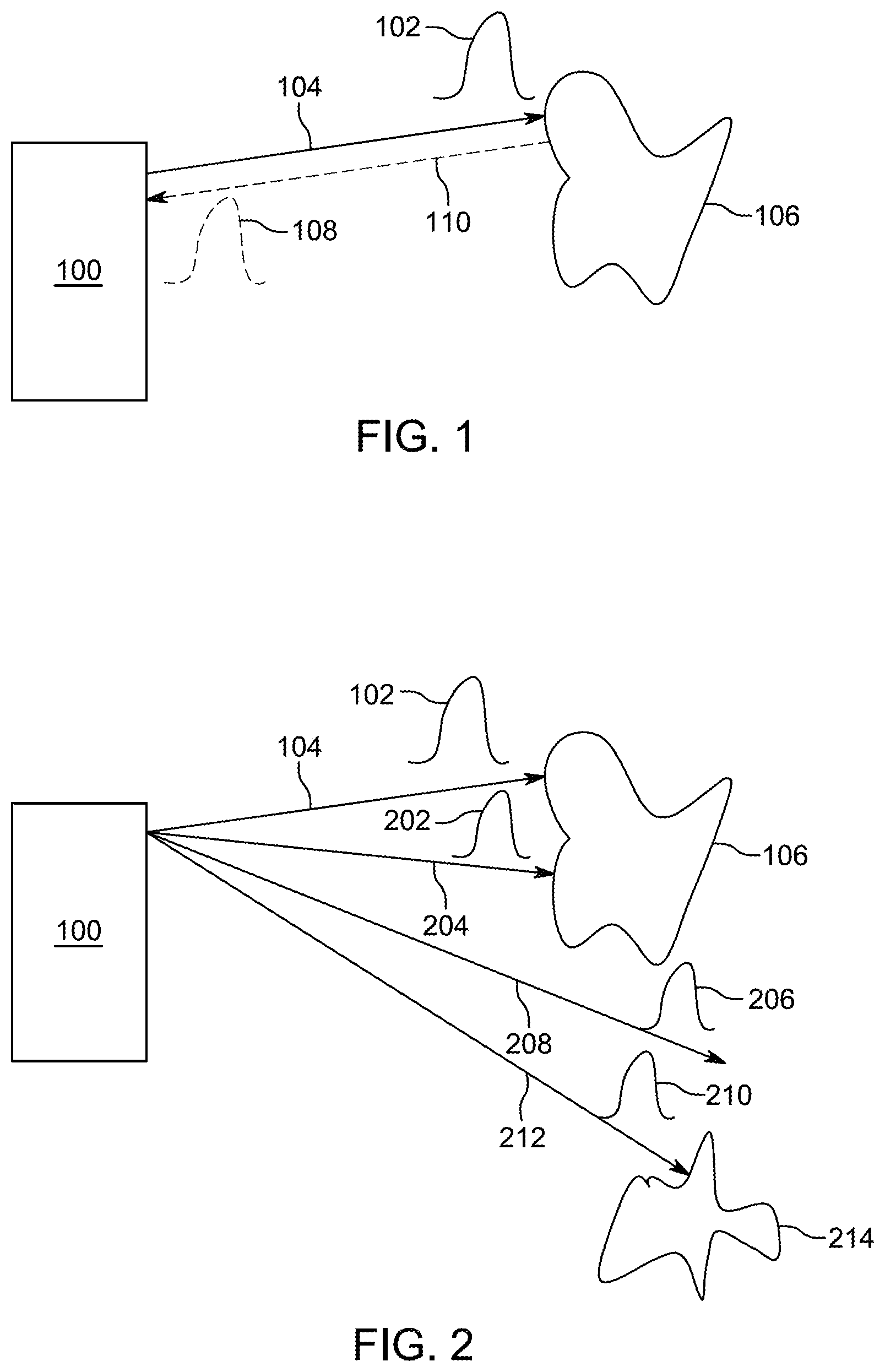
Some LiDAR systems use the time-of-flight of light signals (e.g., light pulses) to determine the distance to objects in the path of the light. For example, with respect to , an exemplary LiDAR system 100 includes a laser light source (e.g., a fiber laser), a steering system (e.g., a system of one or more moving mirrors), and a light detector (e.g., a photon detector with one or more optics). LiDAR system 100 transmits light pulse 102 along path 104 as determined by the steering system of LiDAR system 100 . In the depicted example, light pulse 102 , which is generated by the laser light source, is a short pulse of laser light. Further, the signal steering system of the LiDAR system 100 is a pulse signal steering system. However, it should be appreciated that LiDAR systems can operate by generating, transmitting, and detecting light signals that are not pulsed and/use derive ranges to object in the surrounding environment using techniques other than time-of-flight. For example, some LiDAR systems use frequency modulated continuous waves (i.e., “FMCW”). It should be further appreciated that any of the techniques described herein with respect to time-of-flight based systems that use pulses also may be applicable to LiDAR systems that do not use one or both of these techniques.
Referring back to (a time-of-flight LiDAR system that uses light pulses) when light pulse 102 reaches object 106 , light pulse 102 scatters and returned light pulse 108 will be reflected back to system 100 along path 110 . The time from when transmitted light pulse 102 leaves LiDAR system 100 to when returned light pulse 108 arrives back at LiDAR system 100 can be measured (e.g., by a processor or other electronics within the LiDAR system). This time-of-flight combined with the knowledge of the speed of light can be used to determine the range/distance from LiDAR system 100 to the point on object 106 where light pulse 102 scattered.
By directing many light pulses, as depicted in , LiDAR system 100 scans the external environment (e.g., by directing light pulses 102 , 202 , 206 , 210 along paths 104 , 204 , 208 , 212 , respectively). As depicted in , LiDAR system 100 receives returned light pulses 108 , 302 , 306 (which correspond to transmitted light pulses 102 , 202 , 210 , respectively) back after objects 106 and 214 scatter the transmitted light pulses and reflect pulses back along paths 110 , 304 , 308 , respectively. Based on the direction of the transmitted light pulses (as determined by LiDAR system 100 ) as well as the calculated range from LiDAR system 100 to the points on objects that scatter the light pulses (e.g., the points on objects 106 and 214 ), the surroundings within the detection range (e.g., the field of view between path 104 and 212 , inclusively) can be precisely plotted (e.g., a point cloud or image can be created).
If a corresponding light pulse is not received for a particular transmitted light pulse, then it can be determined that there are no objects within a certain range of LiDAR system 100 (e.g., the max scanning distance of LiDAR system 100 ). For example, in , light pulse 206 will not have a corresponding returned light pulse (as depicted in ) because it did not produce a scattering event along its transmission path 208 within the predetermined detection range. LiDAR system 100 (or an external system communication with LiDAR system 100 ) can interpret this as no object being along path 208 within the detection range of LiDAR system 100 .
In , transmitted light pulses 102 , 202 , 206 , 210 can be transmitted in any order, serially, in parallel, or based on other timings with respect to each other. Additionally, while depicts a 1-dimensional array of transmitted light pulses, LiDAR system 100 optionally also directs similar arrays of transmitted light pulses along other planes so that a 2-dimensional array of light pulses is transmitted. This 2-dimentional array can be transmitted point-by-point, line-by-line, all at once, or in some other manner. The point cloud or image from a 1-dimensional array (e.g., a single horizontal line) will produce 2-dimensional information (e.g., (1) the horizontal transmission direction and (2) the range to objects). The point cloud or image from a 2-dimensional array will have 3-dimensional information (e.g., (1) the horizontal transmission direction, (2) the vertical transmission direction, and (3) the range to objects).
The density of points in point cloud or image from a LiDAR system 100 is equal to the number of pulses divided by the field of view. Given that the field of view is fixed, to increase the density of points generated by one set of transmission-receiving optics, the LiDAR system should fire a pulse more frequently, in other words, a light source with a higher repetition rate is needed. However, by sending pulses more frequently the farthest distance that the LiDAR system can detect may be more limited. For example, if a returned signal from a far object is received after the system transmits the next pulse, the return signals may be detected in a different order than the order in which the corresponding signals are transmitted and get mixed up if the system cannot correctly correlate the returned signals with the transmitted signals. To illustrate, consider an exemplary LiDAR system that can transmit laser pulses with a repetition rate between 500 kHz and 1 MHz. Based on the time it takes for a pulse to return to the LiDAR system and to avoid mix-up of returned pulses from consecutive pulses in conventional LiDAR design, the farthest distance the LiDAR system can detect may be 300 meters and 150 meters for 500 kHz and 1 Mhz, respectively. The density of points of a LiDAR system with 500 kHz repetition rate is half of that with 1 MHz. Thus, this example demonstrates that, if the system cannot correctly correlate returned signals that arrive out of order, increasing the repetition rate from 500 kHz to 1 Mhz (and thus improving the density of points of the system) would significantly reduce the detection range of the system.
depicts a logical block diagram of LiDAR system 100 , which includes light source 402 , signal steering system 404 , pulse detector 406 , and controller 408 . These components are coupled together using communications paths 410 , 412 , 414 , 416 , and 418 . These communications paths represent communication (bidirectional or unidirectional) among the various LiDAR system components but need not be physical components themselves. While the communications paths can be implemented by one or more electrical wires, busses, or optical fibers, the communication paths can also be wireless channels or open-air optical paths so that no physical communication medium is present. For example, in one exemplary LiDAR system, communication path 410 is one or more optical fibers, communication path 412 represents an optical path, and communication paths 414 , 416 , 418 , and 420 are all one or more electrical wires that carry electrical signals. The communications paths can also include more than one of the above types of communication mediums (e.g., they can include an optical fiber and an optical path or one or more optical fibers and one or more electrical wires).
LIDAR system 100 can also include other components not depicted in , such as power buses, power supplies, LED indicators, switches, etc. Additionally, other connections among components may be present, such as a direct connection between light source 402 and light detector 406 so that light detector 406 can accurately measure the time from when light source 402 transmits a light pulse until light detector 406 detects a returned light pulse.
depicts a logical block diagram of one example of light source 402 that is based on a laser fiber, although any number of light sources with varying architecture could be used as part of the LiDAR system. Light source 402 uses seed 502 to generate initial light pulses of one or more wavelengths (e.g., 1550 nm), which are provided to wavelength-division multiplexor (WDM) 504 via fiber 503 . Pump 506 also provides laser power (of a different wavelength, such as 980 nm) to WDM 504 via fiber 505 . The output of WDM 504 is provided to pre-amplifiers 508 (which includes one or more amplifiers) which provides its output to combiner 510 via fiber 509 . Combiner 510 also takes laser power from pump 512 via fiber 511 and provides pulses via fiber 513 to booster amplifier 514 , which produces output light pulses on fiber 410 . The outputted light pulses are then fed to steering system 404 . In some variations, light source 402 can produce pulses of different amplitudes based on the fiber gain profile of the fiber used in the source. Communication path 416 couples light source 402 to controller 408 ( ) so that components of light source 402 can be controlled by or otherwise communicate with controller 408 . Alternatively, light source 402 may include its own controller. Instead of controller 408 communicating directly with components of light source 402 , a dedicated light source controller communicates with controller 408 and controls and/or communicates with the components of light source 402 . Light source 402 also includes other components not shown, such as one or more power connectors, power supplies, and/or power lines.
Some other light sources include one or more laser diodes, short-cavity fiber lasers, solid-state lasers, and/or tunable external cavity diode lasers, configured to generate one or more light signals at various wavelengths. In some examples, light sources use amplifiers (e.g., pre-amps or booster amps) include a doped optical fiber amplifier, a solid-state bulk amplifier, and/or a semiconductor optical amplifier, configured to receive and amplify light signals.
Returning to , signal steering system 404 includes any number of components for steering light signals generated by light source 402 . In some examples, signal steering system 404 may include one or more optical redirection elements (e.g., mirrors or lens) that steer light pulses (e.g., by rotating, vibrating, or directing) along a transmit path to scan the external environment. For example, these optical redirection elements may include MEMS mirrors, rotating polyhedron mirrors, or stationary mirrors to steer the transmitted pulse signals to different directions. Signal steering system 404 optionally also includes other optical components, such as dispersion optics (e.g., diffuser lenses, prisms, or gratings) to further expand the coverage of the transmitted signal in order to increase the LiDAR system 100 's transmission area (i.e., field of view). In some examples, signal steering system 404 does not contain any active optical components (e.g., it does not contain any amplifiers). In some other examples, one or more of the components from light source 402 , such as a booster amplifier, may be included in signal steering system 404 . In some instances, signal steering system 404 can be considered a LIDAR head or LiDAR scanner.
Some implementations of signal steering systems include one or more optical redirection elements (e.g., mirrors or lens) that steers returned light signals (e.g., by rotating, vibrating, or directing) along a receive path to direct the returned light signals to the light detector. The optical redirection elements that direct light signals along the transmit and receive paths may be the same components (e.g., shared), separate components (e.g., dedicated), and/or a combination of shared and separate components. This means that in some cases the transmit and receive paths are different although they may partially overlap (or in some cases, substantially overlap).
depicts a logical block diagram of one possible arrangement of components in light detector 404 of LiDAR system 100 ( ). Light detector 404 includes optics 604 (e.g., a system of one or more optical lenses) and detector 602 (e.g., a charge coupled device (CCD), a photodiode, an avalanche photodiode, a photomultiplier vacuum tube, an image sensor, etc.) that is connected to controller 408 ( ) via communication path 418 . The optics 604 may include one or more photo lenses to receive, focus, and direct the returned signals. Light detector 404 can include filters to selectively pass light of certain wavelengths. Light detector 404 can also include a timing circuit that measures the time from when a pulse is transmitted to when a corresponding returned pulse is detected. This data can then be transmitted to controller 408 ( ) or to other devices via communication line 418 . Light detector 406 can also receive information about when light source 402 transmitted a light pulse via communication line 418 or other communications lines that are not shown (e.g., an optical fiber from light source 402 that samples transmitted light pulses). Alternatively, light detector 404 can provide signals via communication line 418 that indicate when returned light pulses are detected. Other pulse data, such as power, pulse shape, and/or wavelength, can also be communicated.
Returning to , controller 408 contains components for the control of LiDAR system 100 and communication with external devices that use the system. For example, controller 408 optionally includes one or more processors, memories, communication interfaces, sensors, storage devices, clocks, ASICs, FPGAs, and/or other devices that control light source 402 , signal steering system 404 , and/or light detector 406 . In some examples, controller 408 controls the power, rate, timing, and/or other properties of light signals generated by light source 402 ; controls the speed, transmit direction, and/or other parameters of light steering system 404 ; and/or controls the sensitivity and/or other parameters of light detector 406 .
Controller 408 optionally is also configured to process data received from these components. In some examples, controller determines the time it takes from transmitting a light pulse until a corresponding returned light pulse is received; determines when a returned light pulse is not received for a transmitted light pulse; determines the transmitted direction (e.g., horizontal and/or vertical information) for a transmitted/returned light pulse; determines the estimated range in a particular direction; and/or determines any other type of data relevant to LiDAR system 100 .
shows illustrative laser pulses according to an embodiment. In particular, shows conventional pulse 705 and ultrashort pulses 710 . Conventional pulse 705 can represent a pulse having a relatively long pulse duration (e.g., on the order of nanoseconds) as compared to the ultrashort pulses 710 , which have relatively short durations (e.g., on the order of picoseconds). Ultrashort pulses 710 may be several orders of magnitudes shorter than conventional pulses 705 . For example, ultrashort pulses 710 can be in the picosecond range, for example, ranging from 10 picoseconds to 900 picoseconds, or more particularly ranging between 100 and 200 picoseconds. As such, several ultrashort pulses 710 can be emitted during the span of one convention pulse 705 . Conventional pulse 705 embodies higher average power than ultrashort pulses 710 that are emitted over the pulse duration of conventional pulse 705 . However, each ultrashort pulse 710 has higher peak power than conventional pulse 705 , but the average power consumed by ultrashort pulses 710 is much less than the average power of conventional pulse 705 .
shows an illustrative LiDAR system 800 according to an embodiment. LiDAR system 800 can include ultrashort pulse controller 810 , laser system 820 , beam steering system 830 , and return beam detection system 840 . Ultrashort pulse controller 810 may control the pulse duration and power intensity of each laser pulse emitted by laser source 820 , and may also control the time intervals between successively emitted laser pulses. Laser system 820 may be similar to light source 402 , beam steering system may be similar to signal steering system 404 , return beam detection system 840 may be similar to light detector 406 . Because the ultrafast pulses are much faster than conventional pulses, special consideration may be taken into account by return beam detection system 840 to quickly and accurately process return signals. Several return beam detection circuitry system embodiments are discussed below.
Advantages of using ultrashort pulses is that it reduces average power consumption by the laser. In addition, the ultrashort pulses may enable the size of beam steering system 830 to shrink. For example, in one embodiment, a 200 picosecond ultrashort pulse may enable the receiving aperture of beam steering system 830 to be reduced down to 200 mm 2 and power consumption to be reduced down to less than 1 W whereas a 4 ns pulse may require that of beam steering system 830 to be sized to approximately 600 mm 2 and power consumption to be more than 10 W. Yet another advantage of using ultra short pulses is that various electronics such as light detecting electronics can be shrunk compared to the size of such electronics needed for conventional light pulses.
shows illustrative return beam detection system 900 according to an embodiment. System 900 can include receiving lenses 910 , fast avalanche photo diode (APD) 920 , analog-to-digital converter (ADC) 930 , and signal detection circuitry 940 . The fast APD 920 monitors for return pulses. Detected return pulses are sent to ADC 930 for conversion from an analog signal to a digital signal. That digital signal can be compared to a threshold by signal detection circuitry 940 to determine whether a return pulse has been detected.
shows illustrative return beam detection system 1000 according to an embodiment. System 1000 can include receiving lenses 1010 , single photon avalanche diode (SPAD) detector 1020 , time-to-digital converter (TDC) 1030 , and signal detection circuitry 1040 . SPAD detector 1020 is very sensitive and generates an output in response to return signals and noise (e.g., ambient sunlight, etc.). TDC 1030 determines the time period between successive outputs generated by SPAD detector 1020 . The determined time periods are provided to signal detection circuitry 1040 . Signal detection circuitry 1040 can evaluate the determined time periods to assess whether a return pulse has been detected. Using TDC 1030 (as opposed to an ADC) eliminates an intensity measurement of the return pulses, and uses a time-dependent measurement of the return pulses. In order to combat the noise issue, ultrashort pulse controller (e.g., controller 810 ) may instruct the laser source to emit successive ultrashort pulses with different periods. For example, shows an illustrative sequence of ultrashort pulses 1101 - 1104 that are successively emitted at different periods or time delays T 1 -T 3 , where T 1 ≠T 2 ≠T 3 . By varying the periods, signal detection circuitry 1040 can more readily discern whether SPAD signals belong to a real return signal or noise. This can be done by correlating the determined time periods with the varying periods. shows a correlated return pulse signal 1201 surround by noise signals 1202 . In addition, by varying the periods of successive laser pulses, signal detection circuitry 1040 can detect return pulses within 2-3 ms as opposed to techniques that do not dither the successive laser pulses, which can take 100 ms or more to detect return pulses.
System 1000 may not be able to determine intensity of the return light pulse because it is set up to detect time delays between returned pulses. If desired, system 1000 may be used in combination with a camera that can be used to obtain intensity information related to the light pulse.
In some embodiments, the SPAD detector can be based on InGaAs, which can detect light in the 900-1700 nm wavelengths. In another embodiment the SPAD detector can be based on a silicon photo multitube (SiPM), which can detect light in the 400-1050 nm wavelengths.
shows illustrative process 1300 according to an embodiment. Starting at step 1310 , a plurality of ultrashort light pulses can be transmitted to a steering system that redirects the light pulses to a LiDAR field of view, wherein a time delay between successively transmitted ultrashort light pulses is varied. At step 1320 , light energy signals are received via a detection system. The light energy signals can include at least one of noise and returned ultrashort pulses. At step 1330 , a time interval between successively received light energy signals is determined. At step 1340 , the determined time interval can be correlated with the time delay to distinguish between noise and returned ultrashort pulses.
It should be understood that the steps shown in are merely illustrative and that additional steps may be added, that some steps may be omitted, and that some steps may rearranged.
shows illustrative process 1400 according to an embodiment. Starting at step 1410 , a plurality of ultrashort light pulses can be transmitted to a steering system that redirects the light pulses to a LiDAR field of view. At step 1420 , light energy signals are received via a detection system. The light energy signals can include noise and returned ultrashort pulses, wherein each received light energy signal produces an analog intensity level. At step 1430 , the analog intensity level is converted to a digital intensity level. At step 1440 , the digital intensity level is compared to a threshold to distinguish between noise and returned ultrashort pulses.
It should be understood that the steps shown in are merely illustrative and that additional steps may be added, that some steps may be omitted, and that some steps may rearranged.
shows illustrative return beam detection system 1500 according to an embodiment. System 1500 can include receiving lenses 1510 , avalanche photo diode (APD) detector 1520 , limiting transimpedance amplifier (LTA) 1530 , time-to-digital converter (TDC) 1540 , laser reference clock 1550 , and signal detection circuitry 1560 . APD 1520 monitors for return pulses. APD 1520 produces a current signal based on the detected return pulse. The current signal may have a period approximately equal to the ultrashort pulse. LTA 1530 converts the current signal obtained by APD 1520 into a square wave signal. The square wave signal has a period that is approximately the same as the period of the light pulse received by receiving lens 1510 . The square wave signal is provided to TDC 1540 . TDC 1540 also receives laser reference clock 1550 . Laser reference clock 1550 corresponds to transmission of each light pulse by the laser system (not shown). TDC 1540 is able to determine a time delay between a reference clock and the rising edge of square wave for any given light pulse. Each light pulse includes the originating light pulse being emitted by the laser source and a return pulse. Each originating light pulse corresponds to the laser reference clock 1550 and each return pulse is represented by the square wave generated by the LTA 1530 . The time delay between the reference clock and the square wave is used to calculate the distance of the object responsible for returning the return pulse.
shows an illustrative timing diagram according to an embodiment. As shown, laser source 1605 transmits a laser pulse that corresponds to REF CLK pulse transmitted by laser reference clock 1650 . A return pulse, reflected by an object in the LiDAR system's field of view, is detected by the APD, which produces illustrative current signal 1610 , which is sent to the LTA. The LTA converts current signal 1610 into square wave signal 1620 . Square signal 1620 and REF CLK are compared by the TDC to determine the time delay (ta) between square wave signal 1620 and REF CLK. The time delay can be used to determine the distance to the object responsible for returning the return pulse.
shows an illustrative process 1700 according to an embodiment. Process 1700 may be implemented in system 1500 . Starting at step 1710 , a plurality of ultrashort light pulses can be transmitted to a steering system that redirects the light pulses to a LiDAR field of view, wherein each transmitted ultrashort light pulse corresponds to a reference clock. At step 1720 , light energy signals are received via a detection system, wherein each received light energy signal produces a current level. For example, ADP 1520 may produce a current level based on the returned ultrashort pulse. At step 1730 , the current level is converted to a square wave signal. For example, LTA 1530 may generate the square wave signal. At step 1740 , the square wave signal is compared to the reference clock pulse to obtain a time delay between transmission of an ultrashort light pulse and a return of that particular ultrashort light pulse. For example, TDC 1540 may determine the time delay.
It should be understood that the steps shown in are merely illustrative and that additional steps may be added, that some steps may be omitted, and that some steps may rearranged.
Various exemplary embodiments are described herein. Reference is made to these examples in a non-limiting sense. They are provided to illustrate more broadly applicable aspects of the disclosed technology. Various changes may be made and equivalents may be substituted without departing from the true spirit and scope of the various embodiments. In addition, many modifications may be made to adapt a particular situation, material, composition of matter, process, process act(s) or step(s) to the objective(s), spirit or scope of the various embodiments. Further, as will be appreciated by those with skill in the art, each of the individual variations described and illustrated herein has discrete components and features which may be readily separated from or combined with the features of any of the other several embodiments without departing from the scope or spirit of the various embodiments.
Figures (10)
Citations
This patent cites (314)
- US3897150
- US4464048
- US4923263
- US5006721
- US5157451
- US5319434
- US5369661
- US5442358
- US5546188
- US5579153
- US5657077
- US5793491
- US5838239
- US5864391
- US5926259
- US5936756
- US6163378
- US6317202
- US6594000
- US6650404
- US6950733
- US7128267
- US7202941
- US7345271
- US7382442
- US7440084
- US7440175
- US7489865
- US7502395
- US7508496
- US7576837
- US7583364
- US7830527
- US7835068
- US7847235
- US7880865
- US7936448
- US7969558
- US7982861
- US8072582
- US8471895
- US8736818
- US8749764
- US8812149
- US8994928
- US9041762
- US9048616
- US9065243
- US9086273
- US9121703
- US9194701
- US9255790
- US9300321
- US9304316
- US9316724
- US9354485
- US9510505
- US9575184
- US9605998
- US9621876
- US9638799
- US9696426
- US9702966
- US9804264
- US9810786
- US9812838
- US9823353
- US9857468
- US9869754
- US9880263
- US9880278
- US9885778
- US9897689
- US9915726
- US9927915
- US9958545
- US10007001
- US10012732
- US10042159
- US10061019
- US10073166
- US10078133
- US10094925
- US10157630
- US10185027
- US10191155
- US10215847
- US10267898
- US10295656
- US10310058
- US10324170
- US10324185
- US10393877
- US10422865
- US10429495
- US10444356
- US10451716
- US10466342
- US10502831
- US10509112
- US10520602
- US10557923
- US10571567
- US10578720
- US10591600
- US10627491
- US10641872
- US10663564
- US10663585
- US10663596
- US10684360
- US10732281
- US10908262
- US10908265
- US10908268
- US10969475
- US10983218
- US11002835
- US11009605
- US11016192
- US11022689
- US11035935
- US11194048
- US2002/0136251
- US2004/0135992
- US2005/0033497
- US2005/0190424
- US2005/0195383
- US2006/0071846
- US2006/0132752
- US2007/0091948
- US2007/0216995
- US2008/0174762
- US2008/0193135
- US2009/0010644
- US2009/0051926
- US2009/0059201
- US2009/0067453
- US2009/0147239
- US2009/0262760
- US2009/0316134
- US2010/0006760
- US2010/0020306
- US2010/0020377
- US2010/0027602
- US2010/0045965
- US2010/0053715
- US2010/0128109
- US2010/0271614
- US2011/0181864
- US2012/0038903
- US2012/0124113
- US2012/0221142
- US2013/0107016
- US2013/0116971
- US2013/0241761
- US2013/0293867
- US2013/0293946
- US2013/0329279
- US2013/0342822
- US2014/0078514
- US2014/0104594
- US2014/0347650
- US2014/0350836
- US2015/0078123
- US2015/0084805
- US2015/0109603
- US2015/0116692
- US2015/0139259
- US2015/0158489
- US2015/0338270
- US2015/0355327
- US2016/0003946
- US2016/0006914
- US2016/0047896
- US2016/0047900
- US2016/0061655
- US2016/0061935
- US2016/0100521
- US2016/0117048
- US2016/0172819
- US2016/0178736
- US2016/0226210
- US2016/0245902
- US2016/0291134
- US2016/0313445
- US2016/0327646
- US2017/0003116
- US2017/0153319
- US2017/0219695
- US2017/0242104
- US2017/0299721
- US2017/0307738
- US2017/0328991
- US2017/0365105
- US2018/0040171
- US2018/0050704
- US2018/0069367
- US2018/0152691
- US2018/0158471
- US2018/0164439
- US2018/0156896
- US2018/0188355
- US2018/0188357
- US2018/0188358
- US2018/0188371
- US2018/0210084
- US2018/0275274
- US2018/0284241
- US2018/0284242
- US2018/0284286
- US2018/0329060
- US2018/0359460
- US2019/0025428
- US2019/0107607
- US2019/0107623
- US2019/0120942
- US2019/0120962
- US2019/0154804
- US2019/0154807
- US2019/0212416
- US2019/0250254
- US2019/0257924
- US2019/0265334
- US2019/0265336
- US2019/0265337
- US2019/0265339
- US2019/0277952
- US2019/0310368
- US2019/0369215
- US2019/0369258
- US2019/0383915
- US2020/0142070
- US2020/0256964
- US2020/0284906
- US2020/0319310
- US2020/0400798
- US2021/0088630
- US2022/0390572
- US1677050
- US204758260
- US204885804
- US108132472
- US207457508
- US207557465
- US208314210
- US208421228
- US208705506
- US10659747
- US209280923
- US108445468
- US110031823
- US108089201
- US109116331
- US109917408
- US109116366
- US109116367
- US110031822
- US211655309
- US109188397
- US109814086
- US109917348
- US110492856
- US110736975
- US109725320
- US110780284
- US110780283
- US110784220
- US212623082
- US110492349
- US109950784
- US213182011
- US213750313
- US214151038
- US109814082
- US113491043
- US214795200
- US214795206
- US214895784
- US214895810
- US215641806
- US112639527
- US215932142
- US112578396
- US0 757 257
- US1 237 305
- US1 923 721
- US2 157 445
- US2 395 368
- US2 889 642
- US1 427 164
- US2000411
- US2007144667
- US2010035385
- US2017-003347
- US2017-138301
- US10-2010-0096931
- US10-2012-0013515
- US10-2013-0068224
- US10-2018-0107673
- US02/101408
- US2017/110417
- US2018/125725
- US2018126248
- US2018129408
- US2018129409
- US2018129410
- US2018175990
- US2018182812
- US2019079642
- US2019165095
- US2019165289
- US2019165294
- US2020013890