Optical Fiber Measurement System, Optical Fiber Measurement Method, Control Arithmetic Device, and Program
Abstract
An optical fiber measurement system is presented. The optical fiber measurement system includes a light incident circuit which makes a probe light incident on one end of an optical fiber and makes a secondary probe light and a pump light as an optical pulse incident on the other end of the optical fiber; a light receiver which measures a light intensity of arbitrary one propagation mode in the probe light propagating through the optical fiber; and a control calculation device which sets a propagation mode of the probe light, the secondary probe light, and the pump light, an optical frequency difference of the secondary probe light, and an optical frequency difference of the pump light with respect to the light incident circuit, and calculates loss and crosstalk at each point in a longitudinal direction of the optical fiber from the light intensity measured by the light receiver.
Claims (7)
1. An optical fiber measurement system comprising: a light incident circuit which makes a probe light incident on one end of an optical fiber and makes a secondary probe light and a pump light as an optical pulse incident on the other end of the optical fiber; a light receiver which measures a light intensity of arbitrary one propagation mode in the probe light propagating through the optical fiber; and a control calculation device which sets a propagation mode of the probe light, the secondary probe light, and the pump light, an optical frequency difference of the secondary probe light with respect to the pump light, and an optical frequency difference of the pump light with respect to the pump light, and calculates loss and crosstalk at each point in a longitudinal direction of the optical fiber, from the light intensity measured by the light receiver, wherein the control calculation device when the optical fiber is connected as the optical fiber, with respect to the light incident circuit, makes the probe light incident on one end of the optical fiber in an arbitrary propagation mode, makes the secondary probe light incident on the other end of the optical fiber in a propagation mode which becomes a crosstalk component of the probe light, where the secondary probe light having an optical frequency difference with the probe light that is lower than the frequency of the probe light, makes the pump light incident in an arbitrary propagation mode, where the pump light having an optical frequency difference with the probe light that is higher than frequency of the probe light, acquires a distribution of a Brillouin amplification amount of the probe light in the longitudinal direction of the optical fiber to be measured from the light intensity, and calculates the loss and crosstalk, using a level difference of the Brillouin amplification amount appearing in the distribution and a Brillouin gain coefficient determined by an optical frequency difference between the pump light and the probe light and a propagation mode.
4. An optical fiber measurement method, using an optical fiber measurement system which includes a light incident circuit which makes a probe light incident on one end of an optical fiber and makes a secondary probe light and a pump light as an optical pulse incident on the other end of the optical fiber, a light receiver which measures a light intensity of arbitrary one propagation mode in the probe light propagating through the optical fiber, and a control calculation device which sets a propagation mode of the probe light, the secondary probe light, and the pump light, an optical frequency difference of the secondary probe light with respect to the probe light, and an optical frequency difference of the pump light with respect to the probe light, and calculates loss and crosstalk at each point in a longitudinal direction of the optical fiber, from the light intensity measured by the light receiver, wherein which when the optical fiber is connected as the optical fiber, making the probe light incident on one end of the optical fiber in an arbitrary propagation mode; making the secondary probe light incident on the other end of the optical fiber in a propagation mode which becomes a crosstalk component of the probe light, where the secondary probe light having the optical frequency difference with the probe light that is lower than the frequency of the probe light; making the pump light incident in an arbitrary propagation mode, where the pump light having the optical frequency difference with the probe light that is higher than frequency of the probe light; acquiring a distribution of a Brillouin amplification amount of the probe light in the longitudinal direction of the optical fiber to be measured from the light intensity; and calculating the loss and crosstalk, using a level difference of the Brillouin amplification amount appearing in the distribution and a Brillouin gain coefficient determined by an optical frequency difference between the pump light and the probe light and a propagation mode.
5. A control calculation device of an optical fiber measurement system comprising: a light incident circuit which makes a probe light incident on one end of an optical fiber and makes a secondary probe light and a pump light as an optical pulse incident on the other end of the optical fiber; and a light receiver which measures a light intensity of arbitrary one propagation mode in the probe light propagating through the optical fiber, wherein the control calculation device includes a control unit which sets a propagation mode of the probe light, the secondary probe light, and the pump light, an optical frequency difference of the secondary probe light with respect to the probe light, and an optical frequency difference of the pump light with respect to the probe light, and a calculation unit which calculates loss and crosstalk at each point in a longitudinal direction of the optical fiber, from the light intensity measured by the light receiver, wherein when the optical fiber is connected to the optical fiber measurement system, with respect to the light incident circuit, the control unit makes the probe light incident on one end of the optical fiber in an arbitrary propagation mode, makes the secondary probe light incident on the other end of the optical fiber in a propagation mode which becomes a crosstalk component of the probe light, where the secondary probe light having the optical frequency difference with the probe light that is lower than the frequency of the probe light, and makes the pump light incident in an arbitrary propagation mode, where the pump light having the optical frequency difference with the probe light that is higher than frequency of the probe light, wherein the calculation unit acquires a distribution of a Brillouin amplification amount of the probe light in the longitudinal direction of the optical fiber to be measured from the light intensity, and calculates the loss and crosstalk, using a level difference of the Brillouin amplification amount appearing in the distribution, an optical frequency difference between the pump light and the probe light, and a Brillouin gain coefficient determined by a propagation mode.
Show 4 dependent claims
2. The optical fiber measurement system according to claim 1 , wherein, when a reference optical fiber having the same characteristics as the optical fiber to be measured and having no mode coupling is connected as the optical fiber, with respect to the light incident circuit, the control calculation device makes the probe light incident on one end of the optical fiber and the pump light incident on the other end of the optical fiber, while changing an optical frequency difference between the probe light and the pump light in a combination of all propagation modes propagating through the optical fiber to be measured, and acquires the Brillouin gain coefficient in a combination of each optical frequency difference and each propagation mode from the light intensity.
3. The optical fiber measurement system according to claim 1 , wherein the control calculation device sets the optical frequency difference between the secondary probe light and the probe light, as the optical frequency difference that gives Brillouin loss only to the crosstalk component of the probe light.
6. The control calculation device according to claim 5 , wherein when a reference optical fiber having the same characteristics as the optical fiber to be measured and having no mode coupling is connected to the optical fiber measurement system as the optical fiber, with respect to the light incident circuit, the control unit makes the probe light incident on one end of the optical fiber and the pump light incident on the other end of the optical fiber, while changing an optical frequency difference between the probe light and the pump light in a combination of all propagation modes propagating through the optical fiber to be measured, and the calculation unit acquires the Brillouin gain coefficient in a combination of each optical frequency difference and each propagation mode from the light intensity.
7. The control calculation device according to claim 5 , wherein the control unit sets the optical frequency difference between the secondary probe light and the probe light as an optical frequency difference that gives Brillouin loss only to a crosstalk component of the probe light.
Full Description
Show full text →
CROSS-REFERENCE TO RELATED APPLICATIONS
This application is a 371 U.S. National Phase of International Application No. PCT/JP2020/038026, filed on Oct. 7, 2020. The entire disclosure of the above application is incorporated herein by reference.
TECHNICAL FIELD
The present disclosure relates to a measurement system, a measurement method thereof, a control calculation device thereof, and a program for measuring loss and crosstalk (XT) generated at each point in an optical fiber transmission line independently.
BACKGROUND ART
In recent years, with rapid increase in transmission traffic, a few-mode fiber (FMF) and a multi-mode fiber (MMF), with which a plurality of propagation modes can be used, have been attracting a lot of attention as fibers that can realize a further increase in capacity, instead of single-mode fiber (SMF) used in current transmission lines. In these fibers, a loss difference between modes (DMA) caused by a difference in loss received for each mode when passing through a connection point or a device such as a mode duplexer, or a crosstalk (XT) in which a part of the mode at the time of incident binds to a different mode occurs. Since DMA and XT are important parameters for signal processing on a receiving side, it is desirable to be able to measure the loss and XT of each mode in the transmission line for each section in order to evaluate the quality of the transmission line.
So far, a method for acquiring propagation characteristics for each mode that uses a Brillouin gain analysis method has been disclosed (see, for example, NPL 1). In this measurement method, the loss and XT received by a pump light can be acquired from the generated gain amount, by controlling a frequency difference between the pump light and a probe light incident on the fiber.
CITATION LIST
Non Patent Literature
[NPL 1]
• T. Oda et al., Proc. ECOC2019, P36 (2019).
SUMMARY OF INVENTION
Technical Problem
When there are a plurality of loss and XT generation points, an XT component of the probe light is generated in the fiber, and a gain by the XT component becomes an error factor. Therefore, the method of the non-patent literature has a problem that it is difficult to measure losses and XT generated at a plurality of points for each point.
In order to solve the above problem, an object of the present invention is to provide an optical fiber measurement system, an optical fiber measurement method, a control calculation device, and a program that are capable of measuring a loss and XT generated at a plurality of points in an optical fiber in which a plurality of modes propagate for each point.
Solution to Problem
In order to achieve the above object, the optical fiber measurement system according to the present invention utilizes two probe light beams and Brillouin gain coefficients between respective modes to decompose gain components into loss and XT components.
Specifically, the optical fiber measurement system according to the present invention includes
•
• a light incident circuit which makes probe light be incident on one end of an optical fiber and makes a secondary probe light and a pump light as an optical pulse incident on the other end of the optical fiber; • a light receiver which measures a light intensity of arbitrary one propagation mode in the probe light propagating through the optical fiber; and • a control calculation device which sets a propagation mode of the probe light, the secondary probe light, and the pump light, and an optical frequency difference of the secondary probe light, and an optical frequency difference of the pump light with respect to the light incident circuit, and calculates a loss and crosstalk at each point in a longitudinal direction of the optical fiber to be measured connected as the optical fiber, from the light intensity measured by the light receiver, • wherein the control calculation device: • when an optical fiber to be measured is connected as the optical fiber, with respect to the light incident circuit, • makes the probe light incident on one end of the optical fiber in an arbitrary propagation mode, • makes the secondary probe light, which has an optical frequency difference from the probe light on a low frequency side, incident on the other end of the optical fiber in a propagation mode which becomes a crosstalk component of the probe light, • makes the pump light, which has an optical frequency difference from the probe light on a high frequency side, incident in an arbitrary propagation mode, • acquires a distribution of a Brillouin amplification amount of the probe light in the longitudinal direction of the optical fiber to be measured from the light intensity, and • calculates the loss and crosstalk, using a level difference of the Brillouin amplification amount appearing in the distribution and a Brillouin gain coefficient determined by an optical frequency difference between the pump light and the probe light and a propagation mode.
In addition, an optical fiber measurement method according to the present invention,
•
• using an optical fiber measurement system which includes a light incident circuit which makes a probe light incident on one end of an optical fiber and makes a secondary probe light and a pump light as an optical pulse incident on the other end of the optical fiber, • a light receiver which measures a light intensity of an arbitrary one propagation mode in the probe light propagating through the optical fiber, and • a control calculation device which sets a propagation mode of the probe light, the secondary probe light, and the pump light, an optical frequency difference of the secondary probe light, and an optical frequency difference of the pump light with respect to the light incident circuit, and calculates loss and crosstalk at each point in a longitudinal direction of the optical fiber to be measured connected as the optical fiber, from the light intensity measured by the light receiver, • wherein • when an optical fiber to be measured is connected as the optical fiber, • making the probe light be incident on one end of the optical fiber in an arbitrary propagation mode; • making the secondary probe light, which has an optical frequency difference from the probe light on a low frequency side, incident on the other end of the optical fiber in a propagation mode which becomes a crosstalk component of the probe light; • making the pump light, which has an optical frequency difference from the probe light on a high frequency side, incident in an arbitrary propagation mode; • acquiring a distribution of a Brillouin amplification amount of the probe light in the longitudinal direction of the optical fiber to be measured from the light intensity; and • calculating the loss and crosstalk, using a level difference of the Brillouin amplification amount appearing in the distribution and a Brillouin gain coefficient determined by an optical frequency difference between the pump light and the probe light and a propagation mode.
Further, according to the present invention, there is provided a control calculation device of an optical fiber measurement system including:
•
• a light incident circuit which makes a probe light incident on one end of an optical fiber and makes a secondary probe light and a pump light as an optical pulse incident on the other end of the optical fiber; and • a light receiver which measures a light intensity of arbitrary one propagation mode in the probe light propagating through the optical fiber, • wherein the control calculation device includes • a control unit which sets a propagation mode of the probe light, the secondary probe light, and the pump light, an optical frequency difference of the secondary probe light, and an optical frequency difference of the pump light with respect to the light incident circuit, and • a calculation unit which calculates loss and crosstalk at each point in a longitudinal direction of the optical fiber to be measured connected as the optical fiber, from the light intensity measured by the light receiver, • wherein • when an optical fiber to be measured as the optical fiber is connected to the optical fiber measurement system, • with respect to the light incident circuit, the control unit makes the probe light incident on one end of the optical fiber in an arbitrary propagation mode, • makes the secondary probe light, which has an optical frequency difference from the probe light on a low frequency side, incident on the other end of the optical fiber in a propagation mode which becomes a crosstalk component of the probe light, and • makes the pump light having an optical frequency difference on a high frequency side from the probe light incident in an arbitrary propagation mode, • wherein the calculation unit • acquires a distribution of a Brillouin amplification amount of the probe light in the longitudinal direction of the optical fiber to be measured from the light intensity, and • calculates the loss and crosstalk, using a level difference of the Brillouin amplification amount appearing in the distribution, an optical frequency difference between the pump light and the probe light, and a Brillouin gain coefficient determined by a propagation mode.
The optical fiber measurement system acquires the distribution of the Brillouin amplification amount of the probe light in the longitudinal direction of the optical fiber, while suppressing the XT component of the probe light, using the secondary probe light. The loss and XT can be calculated for each point, using the level difference of multiple Brillouin amplifications appearing in the distribution and the Brillouin gain coefficient acquired separately. Therefore, the present invention can provide an optical fiber measurement system, an optical fiber measurement method, and a control calculation unit that are capable of measuring the loss and XT generated at a plurality of points of an optical fiber propagating in a plurality of modes for each point.
The Brillouin gain coefficient can be acquired as follows. When a reference optical fiber having the same characteristics as the optical fiber to be measured and having no mode coupling is connected as the optical fiber, with respect to the light incident circuit, the control calculation device makes the probe light incident on one end of the optical fiber and the pump light incident on the other end of the optical fiber, while changing an optical frequency difference between the probe light and the pump light in a combination of all propagation modes propagating through the optical fiber to be measured, and acquires the Brillouin gain coefficient in a combination of each optical frequency difference and each propagation mode from the light intensity.
The control calculation device sets an optical frequency difference between the secondary probe light and the probe light as an optical frequency difference that gives a Brillouin loss only to a crosstalk component of the probe light. The loss and XT can thus be measured accurately.
Further, the present invention is a program that causes a computer to function as the control calculation device. The control calculation device can be realized by a computer and a program, and the program can also be recorded on a recording medium or can also be provided via a network.
Advantageous Effects of Invention
The present invention can provide an optical fiber measurement system, an optical fiber measurement method, a control calculation device, and a program that are capable of measuring loss and XT generated at a plurality of points of an optical fiber, in which a plurality of modes propagate, for each point.
BRIEF DESCRIPTION OF DRAWINGS
is a diagram illustrating an optical fiber measurement system according to the present invention.
is a diagram illustrating examples of Brillouin gain spectra in a two-mode fiber.
is a diagram illustrating the measurement principle of the optical fiber measurement system according to the present invention.
is a diagram illustrating an optical fiber measurement method according to the present invention.
is a diagram illustrating an optical fiber measurement method according to the present invention.
is a diagram illustrating an amplification amount of the probe light measured by the optical fiber measurement system according to the present invention.
is a diagram illustrating an optical fiber measurement system according to the present invention.
DESCRIPTION OF EMBODIMENTS
Embodiments of the present invention will be described with reference to the accompanying drawings. The embodiments described below are examples of the present invention and the present invention is not limited to the following embodiments. Note that constituent elements with the same reference signs in the present description and the drawings are identical to each other.
Embodiment 1
[Device Configuration]
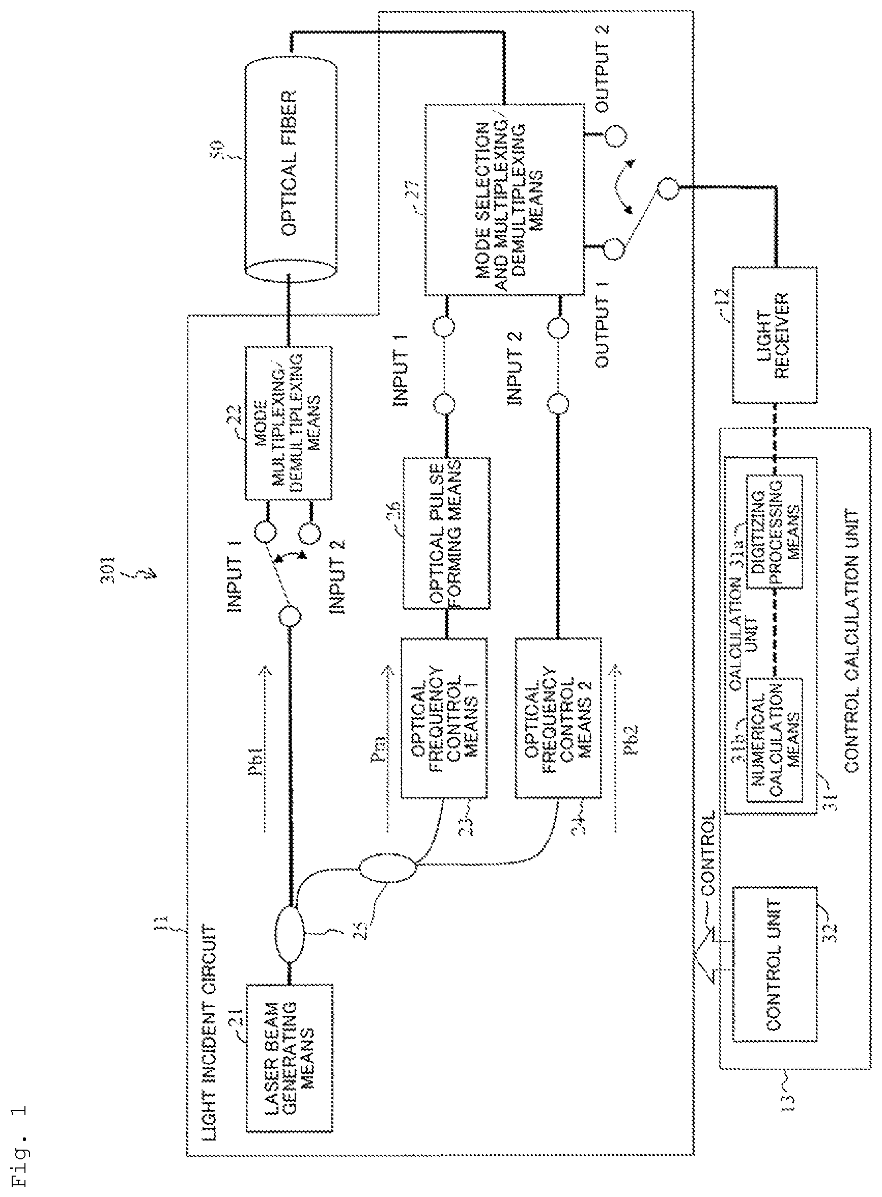
is a diagram illustrating an optical fiber measurement system 301 of the present embodiment. The optical fiber measurement system 301 is an example of the configuration for realizing the present invention. The optical fiber measurement system 301 includes a light incident circuit 11 which makes probe light Pb 1 incident on one end of an optical fiber 50 and makes secondary probe light Pb 2 and pump light Pm as an optical pulse incident on the other end of the optical fiber 50 ,
•
• a light receiver 12 which measures a light intensity of an arbitrary one propagation mode in the probe light Pb 1 propagated through the optical fiber 50 , and • a control calculation device 13 which sets a propagation mode of the probe light Pb 1 , the secondary probe light Pb 2 , and the pump light Pm, an optical frequency difference of the secondary probe light Pb 2 and an optical frequency difference of the pump light Pm with respect to the light incident circuit 11 , and calculates loss and crosstalk at each point in a longitudinal direction of the optical fiber to be measured connected as the optical fiber 50 , from the light intensity measured by the light receiver 12 , in which the control calculation device 13 • when the optical fiber to be measured is connected as the optical fiber 50 , with respect to the light incident circuit 11 , makes the probe light Pb 1 incident on one end of the optical fiber 50 in an arbitrary propagation mode, • makes the secondary probe light Pb 2 having an optical frequency difference from the probe light Pb 1 on a low frequency side incident on the other end of the optical fiber 50 in a propagation mode which becomes a crosstalk component of the probe light Pb 1 , • makes the pump light Pm having an optical frequency difference on a high frequency side from the probe light Pb 1 incident in an arbitrary propagation mode, • acquires a distribution of a Brillouin amplification amount of the probe light Pb 1 in a longitudinal direction of the optical fiber to be measured from the light intensity, and • calculates the loss and crosstalk, using a level difference of the Brillouin amplification amount appearing in the distribution, an optical frequency difference between the pump light Pm and the probe light Pb 1 , and a Brillouin gain coefficient determined by a propagation mode.
The light incident circuit 11 includes a laser beam generating means 21 , a mode multiplexing/demultiplexing means 22 , optical frequency control means 23 and 24 , a branching element 25 , an optical pulse forming means 26 , and a mode selection multiplexing/demultiplexing means 27 .
Light output from the laser beam generating means 21 for generating coherent light is branched into three by the branching element 25 , and becomes the probe light Pb 1 , the pump light Pm, and the secondary probe light Pb 2 , respectively. The pump light Pm is pulsed by the optical pulse forming means 26 after a frequency difference corresponding to the Brillouin frequency shift of the optical fiber to be measured is given to the higher frequency side by the optical frequency control means 23 . On the other hand, a frequency difference of having a lower frequency corresponding to the Brillouin frequency shift of the optical fiber on which measurement is to be performed is applied to the secondary probe light Pb 2 by the optical frequency control means 24 . Since the pump light Pm and the secondary probe light Pb 2 have only to give a frequency difference corresponding to the Brillouin frequency shift to the probe light Pb 1 , three laser light generating means 21 having different optical frequencies are provided without using optical frequency control means 23 and 24 , and the optical frequency difference between the three lasers may be controlled by separately using the light sources of the pump light Pm, the probe light Pb 1 , and the secondary probe light Pb 2 .
The probe light Pb 1 is converted into an arbitrary mode by the mode multiplexing/demultiplexing means 22 and then made incident on one end of the optical fiber to be measured (the optical fiber 50 ). The mode multiplexing/demultiplexing means 22 shown in has a structure that has inputs 1 and 2 , and is switched by a switch. When light is made incident on the input 1 of the mode multiplexing/demultiplexing means 22 , the light is output as a first propagation mode, and when light is made incident on the input 2 , the light is output as a second propagation mode. That is, the mode multiplexing/demultiplexing means 22 can arbitrarily select the propagation mode of the probe light emitted by the switch. The pump light Pm and the secondary probe light Pb 2 are converted into an arbitrary mode by the mode selection multiplexing/demultiplexing means 27 and then made incident on the other end of the optical fiber to be measured.
The probe light Pb 1 and the secondary probe light Pb 2 made incident on the optical fiber to be measured generate a Brillouin interaction in the whole sections of the optical fiber to be measured, and thus, the probe light Pb 1 receives Brillouin loss. Here, a loss is given to an arbitrary mode of the probe light Pb 1 , by controlling a frequency difference between the probe light Pb 1 and the secondary probe light Pb 2 by the optical frequency control means 24 . Thus, the probe light Pb 1 of only a specific mode is made to exist in the optical fiber to be measured.
Also, the Brillouin interaction is generated in the whole sections of the optical fiber to be measured for the pulsed pump light Pm and the probe light Pb 1 made incident on the optical fiber to be measured, and thus, the probe light Pb 1 is Brillouin-amplified. Here, since the pump light Pm is a pulse, an amplification amount of the probe light Pb 1 at each time based on the incident time of the pump light Pm corresponds to the light intensity of the pump light Pm at each point of the optical fiber to be measured. The amplified probe light Pb 1 is converted into an electric signal by the light receiver 12 after a mode is selected by the mode selection multiplexing/demultiplexing means 27 . The mode selection multiplexing/demultiplexing means 27 shown in has a structure which has outputs 1 and 2 , and is switched by a switch. The mode selection multiplexing/demultiplexing means 27 can selectively extract a mode component of the probe light Pb 1 emitted from the mode multiplexing/demultiplexing means 22 by the switch. That is, the mode selection multiplexing/demultiplexing means 27 can output a component of a first propagation mode of the probe light Pb 1 from the output 1 and a second propagation mode component of the probe light Pb 1 from the output 2 by switching the switch.
The control calculation device 13 includes a control unit 32 which sets propagation modes of the probe light Pb 1 , the secondary probe light Pb 2 and the pump light Pm and an optical frequency difference of the secondary probe light Pb 2 and an optical frequency difference of the pump light Pm with respect to the light incident circuit 11 , and a calculation unit 31 which calculates loss and crosstalk at each point in the longitudinal direction of the optical fiber to be measured connected as the optical fiber 50 from the light intensity measured by the light receiver 12 . The calculation unit 31 has a digitizing processing means 31 a and a numerical calculation means 31 b . A reception signal from the light receiver 12 is digitized by the digitizing processing means 31 a , and a Brillouin gain is acquired by the numerical calculation means 31 b . A specific method of analyzing the Brillouin gain is as follows. First, a reference intensity of the probe light Pb 1 when the pump light Pm is not incident is acquired. Thereafter, the signal intensity in the case where the pump light and the probe light pb 1 are incident is acquired. The Brillouin gain can be acquired by calculating the amount of increase in the reference intensity from the signal intensity.
The control unit 32 controls the operation of the light incident circuit 13 . Specifically, the control unit 32 sets an optical frequency difference between the probe light Pb 1 and the pump light Pm and an optical frequency difference between the probe light Pb 1 and the secondary probe light Pb 2 with respect to the optical frequency control means 23 and 24 . The control unit 32 sets a time for making the pump light Pm as the pulse light incident on the optical fiber 50 (sets a position in the optical fiber 50 to be measured), with respect to the optical pulse forming means 26 . Further, the control unit 32 sets the propagation mode of the probe light Pb 1 , the pump light Pm, and the secondary probe light Pb 2 incident on the optical fiber 50 , with respect to the mode multiplexing/demultiplexing means 22 and the mode selection multiplexing/demultiplexing means 27 . That is, the control unit 32 , with respect to the light incident circuit 11 ,
•
• makes the probe light Pb 1 incident on one end of the optical fiber 50 in an arbitrary propagation mode, • makes the secondary probe light Pb 2 having an optical frequency difference from the probe light Pb 1 on the low frequency side incident on the other end of the optical fiber 50 in a propagation mode which becomes a crosstalk component of the probe light Pb 1 , and • makes the pump light Pm having an optical frequency difference on a high frequency side from the probe light Pb 1 incident in an arbitrary propagation mode.
The configurations are examples. As long as a device configuration is adopted in which an optical frequency difference and an incident time difference corresponding to a frequency (wavelength) shift are given between the pump light Pm, the probe light Pb 1 , and the secondary probe light Pb 2 , and the probe light Pb 1 amplified by exciting an arbitrary propagation mode can be extracted in a time domain, any means may be adopted. Further, even in a general single-mode optical fiber (SMF), the optical fiber measurement system 301 can measure SMF by making the incident wavelength shorter than a cutoff wavelength. For this reason, the fiber to be measured may be any fiber having a condition in which a plurality of modes propagate.
[Brillouin Gain and Brillouin Loss Generated Between Plurality of Modes]
In the optical fiber 50 , a Brillouin frequency shift ν b at which Brillouin amplification and loss are maximum is given as follows:
[ Math . 1 ] v b = 2 n i V a λ , ( 1 ) where n i denotes an effective refractive index of the mode, V a denotes an effective velocity of an acoustic wave, and λ denotes a wavelength in vacuum.
That is to say, in an optical fiber through which light in a plurality of modes propagates, it means that the Brillouin frequency shift differs depending on the propagation mode, and the Brillouin gain spectrum in each mode is different for each propagation mode. The present invention utilizes this feature.
For the sake of simplicity, description with a number mode optical fiber (FMF) in which only two modes propagate will be provided. When each of the pump light Pm and the probe light (or the probe light Pb 1 and the secondary probe light Pb 2 ) have an amplitude in both the LP 01 and LP 11 modes, there are three different Brillouin gain spectra of
•
• (i) v 01 - 01 (interaction between pump and probe components of LP 01 ), • (ii)) v 01 - 11 (interaction between the pump component of LP 01 and the probe component of LP 11 , or interaction between the pump component of LP 11 and the probe component of LP 01 ), and • (iii) v 11 - 11 (interaction between pump and probe components of LP 11 ).
By adjusting the optical frequency difference between the pump light Pm, the probe light Pb 1 and the secondary probe light Pb 2 incident on the optical fiber by the use of such properties, amplification and suppression of any mode in the optical fiber can be controlled.
[Acquisition of Brillouin Gain Coefficient]
In the present invention, a Brillouin gain coefficient is used for measurement. Therefore, it is necessary to obtain the Brillouin gain coefficient by some method. In this embodiment, the Brillouin gain coefficient is acquired by a reference optical fiber having the same characteristics as that of the optical fiber to be measured without mode coupling.
The control calculation device 13 ,
•
• when a reference optical fiber having the same characteristics as the optical fiber to be measured and having no mode coupling is connected as the optical fiber 50 , with respect to the light incident circuit 11 , • makes the probe light Pb 1 incident on one end of the optical fiber 50 and the pump light Pm incident on the other end of the optical fiber 50 , while changing an optical frequency difference between the probe light Pb 1 and the pump light Pm in a combination of all propagation modes propagating through the optical fiber to be measured, and • acquires the Brillouin gain coefficient in a combination of each optical frequency difference and each propagation mode from the light intensity.
Since the Brillouin gain spectrum generally has a full width at half maximum (FWHM) of about 30 MHz, when the Brillouin frequency shift ν b for each mode is not sufficiently separated, a Brillouin action occurs at the same time for other mode components. That is, since a gain is generated by a mode other than a desired propagation mode when observing the gain, a gain in which a loss component and an XT component are mixed is generated. A Brillouin gain coefficient between each mode is utilized to decompose the gain component into loss and XT components. The decomposition into the XT component and the loss using the gain coefficient will be described below with reference to a plurality of connection point models. The procedure for acquiring the gain coefficient between the respective modes will be described below.
In the optical fiber in which a plurality of modes propagate, the Brillouin frequency shift and the amount of gain differ depending on the combination of modes to be used. The gain coefficient of each mode is acquired by utilizing the difference. First, a reference optical fiber which exhibits the same characteristics as those of the fiber to be measured and in which no mode coupling occurs in the optical fiber is prepared. Then, gain coefficients of respective modes corresponding to a frequency difference between the pump light Pm and the probe light Pb 1 are acquired by the optical fiber. Here, the reference optical fiber is a fiber having the same number of propagation modes as that of the optical fiber to be measured, and is an optical fiber in which Brillouin spectrum gain generated between the respective modes (the frequency difference of pump-probe light Pb 1 in which a gain is generated and the gain coefficient in the frequency difference thereof) are the same, but there is no mode coupling. That is, the reference optical fiber is used to acquire the Brillouin gain coefficients in advance in a state in which mode coupling has not been occurred.
The gain coefficient is acquired by a combination of the pump light Pm of all propagation modes propagating through the optical fiber to be measured and the probe light Pb 1 of any one propagation mode. That is, in a fiber in which only two modes propagate, when the LP 01 mode is used for the mode of the probe light Pb 1 , as a combination for acquiring a gain coefficient,
•
• (i) v 01 - 01 (interaction between pump and probe components of LP 01 ), and • (ii) v 01 - 11 (interaction between pump component of LP 11 and probe component of LP 01 ) are acquired.
is a diagram illustrating an example of Brillouin gain spectral in the case of a two-mode optical fiber. It can be confirmed from that the gain coefficient of the mode generated by the frequency difference between the pump light and the probe light differs.
The gain coefficient can be acquired, by fixing the power of the propagation mode of the pump light and the probe light, changing the propagation mode of the incident pump light Pm with the propagation mode of the incident probe light Pb 1 fixed, and measuring the gain amount at that time.
[Probe Light XT Component Suppression Due to Brillouin Loss]
When there are a plurality of losses and XT generation points in the optical fiber to be measured, a gain is generated by a component (XT of probe light Pb 1 ) other than the mode of the probe light Pb 1 used when acquiring the gain coefficient, and it becomes difficult to accurately measure the loss and XT accordingly. Therefore, since a loss is given only to the XT component of the probe light Pb 1 , the Brillouin action of the probe light Pb 1 and the secondary probe light Pb 2 is utilized. That is, the control calculation device 13 sets an optical frequency difference between the secondary probe light Pb 2 and the probe light Pb 1 , as an optical frequency difference which gives Brillouin loss only to a crosstalk component of the probe light Pb 1 .
Specifically, in an optical fiber in which only two modes propagate, when a mode of probe light Pb 1 for measuring loss and XT is LP 01 , an LP 11 mode which becomes an XT component of the probe light Pb 1 in the secondary probe light Pb 2 is utilized, and (iii) the action of v 11 - 11 (probe between LP 11 , and interaction between secondary probe components) is utilized.
By generating this action in the whole section of the optical fiber to be measured, the XT component of the probe light Pb 1 can be suppressed.
[Loss And XT Measurement Using Brillouin Gain and Brillouin Loss]
For the explanation of the present embodiment, an optical fiber transmission line model in which there are n connection points (losses and XT generation points) as shown in is considered as an example. In this model, an LP 11 mode is used for the pump light Pm, an LP 01 mode is used for the probe light Pb 1 , and amplification amounts of Brillouin amplification generated in the probe light Pb 1 at collision with the pump light Pm are compared in the longitudinal direction, thereby measuring loss and XT amount generated at each connection point. Further, a frequency difference in which Brillouin interaction is strongly generated by a combination of v 11 - 11 is imparted to the probe light Pb 1 and the secondary probe light Pb 2 , and the secondary probe light Pb 2 of the LP 11 mode is made incident from the incident side of the pump light Pm.
As shown in , when the pump light Pm and the probe light Pb 1 pass through each connection point, two of loss and XT coupled to other mode components are generated. Here, Brillouin interaction between an LP 11 mode which is an XT component of the probe light Pb 1 generated at each connection point and an LP 11 mode of the secondary probe light Pb 2 is generated in the whole section of the optical fiber to be measured, and Brillouin loss Db is given only to the LP 11 mode of the probe light Pb 1 , thereby allowing only the probe light Pb 1 of LP 01 to exist in the fiber.
When the light intensities of the pump light Pm and the probe light Pb 1 made incident on the optical fiber are defined as P r and Pp, respectively, a Brillouin amplification amount ΔPs 01 of the LP 01 probe light Pb 1 generated at the point z of the transmission line can be expressed by z as follows.
[ Math . 2 ] Δ P s 01 ( z ❘ z ≤ z 1 ) = g 01 - 11 η 01 - 01 ← n ~ 2 η ← 1 01 - 01 P r P p , ( 2 ) [ Math . 3 ] Δ P s 01 ( z ❘ z 1 ≤ z ≤ z 2 ) = ( g 01 - 11 η 01 - 01 ← n ~ 2 P r η → 1 11 - 01 P p + g 01 - 01 η 01 - 01 ← n ~ 2 P r η → 1 11 - 01 P p ) η ← 1 01 - 01 , ( 3 ) [ Math . 4 ] Δ P s 01 ( z ❘ z 2 ≤ z ≤ z 3 ) = { g 01 - 01 ( η → 1 11 - 11 η → 2 11 - 01 + η → 1 11 - 12 η → 2 01 - 01 ) + g 01 - 11 ( η → 1 11 - 11 η → 2 11 - 11 + η → 1 11 - 01 η → 2 01 - 11 ) } P p η 01 - 01 ← n ~ 1 P r , ( 4 ) [ Math . 5 ] Δ P s 01 ( z ❘ z n - 1 ≤ z ≤ z n ) = ( g 01 - 01 η 11 - 01 → 1 ~ n - 1 + g 01 - 11 η 11 - 11 → 1 ~ n - 1 ) P p η 01 - 01 ← n ~ 1 P r , ( 5 ) [ Math . 6 ] Δ P s 01 ( z ❘ z n ≤ z ) = { g 01 - 01 ( η 11 - 01 → 1 ~ n - 1 η → n 01 - 01 + η 11 - 11 → 1 ~ n - 1 η → n 11 - 01 ) + g 01 - 11 ( η 11 - 11 → 1 ~ n - 1 η → n 11 - 11 + η 11 - 01 → 1 ~ n - 1 η → n 01 - 11 ) } P p η 01 - 01 → n ~ 1 P r , ( 6 )
Here, g 01-01 and g 01-11 are gain coefficients between LP 01 and LP 01 and LP 01 and LP 11 , respectively, and η k ab-cd is a coupling efficiency from LP ab to LP cd mode at a kth connection point when viewed from the pump light Pm incident side. Here, when k is 1 to n and n to 1, it is a coupling efficiency when passing through the first to nth and nth to first connection points, respectively, and in an arrow attached above η, a “right arrow” indicates the pump light Pm, and a “left arrow” indicates the coupling efficiency of the probe light Pb 1 . For simplicity, propagation loss received by the pump light Pm and the probe light Pb 1 is ignored.
When the Brillouin amplification amounts of Formulas (2) to (5) are compared in the longitudinal direction, the level difference L of the probe amplification amount (see ) observed at each connection point is as follows.
[ Math . 7 ] L 1 = Δ P s 01 ( z ❘ z 1 ≤ z ≤ z 2 ) Δ P s 01 ( z ❘ z ≤ z 1 ) = η → 1 11 - 11 + g 01 - 01 g 01 - 11 η → 1 11 - 01 . ( 7 ) [ Math . 8 ] L 2 = Δ P s 01 ( z ❘ z 2 ≤ z ≤ z 3 ) Δ P s 01 ( z ❘ z 1 ≤ z ≤ z 2 ) = g 01 - 01 ( η → 1 11 - 11 η → 2 11 - 01 + η → 1 11 - 01 η → 2 01 - 01 ) + g 01 - 11 ( η → 1 11 - 11 η → 2 11 - 11 + η → 1 11 - 01 η → 2 01 - 11 g 01 - 01 η → 1 11 - 01 + g 01 - 11 η → 1 11 - 11 . ( 8 ) [ Math . 9 ] L 3 = Δ P s 01 ( z ❘ z 3 ≤ z ≤ z 4 ) Δ P s 01 ( z ❘ z 2 ≤ z ≤ z 3 ) = g 01 - 01 ( η 11 - 11 → 1 ~ 2 η → 3 11 - 01 + η 11 - 01 → 1 ~ 2 η → 3 01 - 01 ) + g 01 - 11 ( η 11 - 11 → 1 ~ 2 η → 3 11 - 11 + η 11 - 01 → 1 ~ 2 η → 3 01 - 11 ) g 01 - 01 η 11 - 01 → 1 ~ 2 + g 01 - 11 η 11 - 11 → 1 ~ 2 . ( 9 ) [ Math . 10 ] L n = Δ P s 01 ( z ❘ z n ≤ z ) Δ P s 01 ( z ❘ z n - 1 ≤ z ≤ z n ) = g 01 - 01 ( η 11 - 11 → 1 ~ n - 1 η → n 11 - 01 + η 11 - 01 → 1 ~ n - 1 η → n 01 - 01 ) + g 01 - 11 ( η 11 - 11 → 1 ~ n - 1 η → n 11 - 11 + η 11 - 01 → 1 ~ n - 1 η → n 01 - 11 ) g 01 - 01 η 11 - 01 → 1 ~ n - 1 + g 01 - 11 η 11 - 11 → 1 ~ n - 1 ( 10 )
From Formulas (7) to (10), it can be seen that the observed level difference is a value including the loss component and the XT component received by the pump light Pm. Further, it can be seen that there is a shape in which L 2 in [Math. 8] and L 3 in [Math. 9] are values including the loss and XT that occur at the connection points before that, and 2 and 3 are substituted for n of L n shown in [Math. 10].
Then, the information of loss and XT is acquired, using the level difference observed at each connection point and the gain coefficient. Here, since all L 2 to L n are expressed by L n , the loss and the XT measuring procedure occurring at the first connection point using L 1 , and the loss and the XT measuring procedure occurring at the n-th connection point using L n will be described below.
(i) Loss and XT at the First Connection Point
As shown in [Math. 7], L 1 is expressed by the gain coefficient between the loss of LP 11 and XT and mode, where L 1 and the gain coefficient utilize the characteristic depending on the frequency difference ν between the pump and probe. When the frequency difference is taken into consideration, L 1 of [Math. 7] is expressed as follows.
[ Math . 11 ] L 1 ( v ) = η → 1 11 - 11 g 01 - 01 ( v ) g 01 - 11 ( v ) η → 1 11 - 01 = η → 1 11 - 11 + K ( v ) η → 1 11 - 01 . ( 11 )
Here, K(ν) is a ratio of g 01-01 (ν) and g 01-11 (ν). When the results acquired at the two frequency differences of ν 2 and ν 2 are utilized, the loss and XT generated at the connection point 1 (z1) can be expressed as follows.
[ Math . 12 ] η → 1 11 - 11 = K ( v 1 ) L 1 ( v 2 ) - K ( v 2 ) L 1 ( v 1 ) K ( v 1 ) - K ( v 2 ) . ( 12 ) [ Math . 13 ] η → 1 11 - 01 = L 1 ( v 1 ) - L 1 ( v 2 ) K ( v 1 ) - K ( v 2 ) . ( 13 )
Here, since K and L 1 can be measured respectively, a loss generated at the connection point 1 can be acquired using [Math. 12], and XT can be acquired using [Math. 13].
(ii) Loss and XT at the n-th Connection Point
Similar to the processing of (i), the characteristics in which the L n and the gain coefficient depend on the frequency difference ν between the pump and the probe are utilized. Considering the frequency difference, L n in [Math. 10] is expressed as follows:
[ Math . 14 ] L n ( v ) = g 01 - 01 ( v ) ( η 11 - 11 → 1 ~ n - 1 η → n 11 - 01 + η 11 - 01 → 1 ~ n - 1 η → n 01 - 01 ) + g 01 - 11 ( v ) ( η 11 - 11 → 1 ~ n - 1 η → n 11 - 11 + η 11 - 01 → 1 ~ n - 1 η → n 01 - 11 ) g 01 - 01 ( v ) η 11 - 01 → 1 ~ n - 1 + g 01 - 11 ( v ) η 11 - 11 → 1 ~ n - 1 . ( 14 )
Here, it is assumed that the denominator of [Math. 14] is deformed to I(ν).
[ Math . 15 ] L n ( v ) I ( v ) = g 01 - 01 ( v ) ( η 11 - 11 → 1 ~ n - 1 η → n 11 - 01 + η 11 - 01 → 1 ~ n - 1 η → n 01 - 01 ) + g 01 - 11 ( v ) ( η 11 - 11 → 1 ~ n - 1 η → n 11 - 11 + η 11 - 01 → 1 ~ n - 1 η → n 01 - 11 ) , ( 15 )
When the results acquired in four frequency differences of ν 1 , ν 2 , ν 3 , and ν 4 are utilized
[ Math . 16 ] [ L n ( v 1 ) I ( v 1 ) L n ( v 2 ) I ( v 2 ) L n ( v 3 ) I ( v 3 ) L n ( v 4 ) I ( v 4 ) ] = ( 16 ) [ g 01 - 01 ( v 1 ) η 11 - 01 → 1 ~ n - 1 g 01 - 11 ( v 1 ) η 11 - 01 → 1 ~ n - 1 g 01 - 01 ( v 1 ) η 11 - 11 → 1 ~ n - 1 g 01 - 11 ( v 1 ) η 11 - 11 → 1 ~ n - 1 g 01 - 01 ( v 2 ) η 11 - 01 → 1 ~ n - 1 g 01 - 11 ( v 2 ) η 11 - 01 → 1 ~ n - 1 g 01 - 01 ( v 2 ) η 11 - 11 → 1 ~ n - 1 g 01 - 11 ( v 2 ) η 11 - 11 → 1 ~ n - 1 g 01 - 01 ( v 3 ) η 11 - 01 → 1 ~ n - 1 g 01 - 11 ( v 3 ) η 11 - 01 → 1 ~ n - 1 g 01 - 01 ( v 3 ) η 11 - 11 → 1 ~ n - 1 g 01 - 11 ( v 3 ) η 11 - 11 → 1 ~ n - 1 g 01 - 01 ( v 4 ) η 11 - 01 → 1 ~ n - 1 g 01 - 11 ( v 4 ) η 11 - 01 → 1 ~ n - 1 g 01 - 01 ( v 4 ) η 11 - 11 → 1 ~ n - 1 g 01 - 11 ( v 4 ) η 11 - 11 → 1 ~ n - 1 ] [ η → n 01 - 01 η → n 01 - 11 η → n 11 - 01 η → n 11 - 11 ] , is expressed as. In [Math. 16], when the inverse matrix of the matrix including the gain coefficient is multiplied, [Math. 16] can be modified as follows.
[ Math . 17 ] [ η → n 01 - 01 η → n 01 - 11 η → n 11 - 01 η → n 11 - 11 ] = ( 17 ) [ g 01 - 01 ( v 1 ) η 11 - 01 → 1 ~ n - 1 g 01 - 11 ( v 1 ) η 11 - 01 → 1 ~ n - 1 g 01 - 01 ( v 1 ) η 11 - 11 → 1 ~ n - 1 g 01 - 11 ( v 1 ) η 11 - 11 → 1 ~ n - 1 g 01 - 01 ( v 2 ) η 11 - 01 → 1 ~ n - 1 g 01 - 11 ( v 2 ) η 11 - 01 → 1 ~ n - 1 g 01 - 01 ( v 2 ) η 11 - 11 → 1 ~ n - 1 g 01 - 11 ( v 2 ) η 11 - 11 → 1 ~ n - 1 g 01 - 01 ( v 3 ) η 11 - 01 → 1 ~ n - 1 g 01 - 11 ( v 3 ) η 11 - 01 → 1 ~ n - 1 g 01 - 01 ( v 3 ) η 11 - 11 → 1 ~ n - 1 g 01 - 11 ( v 3 ) η 11 - 11 → 1 ~ n - 1 g 01 - 01 ( v 4 ) η 11 - 01 → 1 ~ n - 1 g 01 - 11 ( v 4 ) η 11 - 01 → 1 ~ n - 1 g 01 - 01 ( v 4 ) η 11 - 11 → 1 ~ n - 1 g 01 - 11 ( v 4 ) η 11 - 11 → 1 ~ n - 1 ] - 1 [ L n ( v 1 ) I ( v 1 ) L n ( v 2 ) I ( v 2 ) L n ( v 3 ) I ( v 3 ) L n ( v 4 ) I ( v 4 ) ] .
Here, L 1 can be measured, and g 01-01 and g 01-11 can be acquired in advance. Further, since can be calculated from the measured value of the loss and XT at all the connection points from the connection point 1 to the connection point n−1, I(ν 1 ) to I(ν 4 ) can also be acquired. Therefore, the loss and XT generated at the connection point n can be acquired, using [Math. 17].
In other words, the calculation unit 31
•
• acquires a distribution of a Brillouin amplification amount of the probe light Pb 1 in a longitudinal direction of the optical fiber to be measured from the light intensity, and • calculates the loss and crosstalk, by utilizing a level difference L of the Brillouin amplification amount appearing in the distribution, and a Brillouin gain coefficient determined by an optical frequency difference between the pump light Pm and the probe light Pb 1 and a propagation mode.
are diagrams showing the optical fiber measurement method performed by the optical fiber measurement system 301 . The present optical fiber measurement method is an example in which the Brillouin gain coefficient is acquired using the reference optical fiber first.
is a flow chart that explains a step 1 for acquiring the Brillouin gain coefficient. In the step 1, first, a reference optical fiber having no mode coupling showing the same characteristics as the optical fiber to be measured is prepared and connected to the optical fiber measurement system 301 (step S 11 ). Next, the control unit 32 sets an optical frequency difference between the probe light Pb 1 and the pump light Pm with respect to the optical frequency control means 23 (step S 12 ). Further, the control unit 32 sets a propagation mode of the pump light Pm and the probe light Pb 1 to be propagated to the reference optical fiber, with respect to the mode multiplexing/demultiplexing means 22 and the mode selection multiplexing/demultiplexing means 27 (step S 13 ). The mode multiplexing/demultiplexing means 22 and the mode selection multiplexing/demultiplexing means 27 make the pump light Pm and the probe light Pb 1 incident on a reference optical fiber (step S 14 ). The calculation unit 31 acquires a gain coefficient of a Brillouin gain generated in the probe light Pb 1 (step S 16 ). The control unit 32 determines whether all the Brillouin gain coefficients used in the optical fiber to be measured (all combinations of the pump light Pm and the probe light Pb 1 for all propagation modes propagating in the optical fiber to be measured) are acquired (step S 16 ). If there is a non-acquired combination (“No” in step S 16 ), the work from step S 12 is repeated. If all combinations are acquired (“Yes” in step S 16 ), the process proceeds to step 2.
is a flowchart which explains step 2 for measuring loss and XT at the connection point of the optical fiber to be measured. First, the optical fiber to be measured is connected to an optical fiber measurement system 301 (step S 20 ). Next, the control unit 32 sets an optical frequency difference between the probe light Pb 1 and the pump light Pm and the secondary probe light Pb 2 with respect to the optical frequency control means 23 and 24 (step S 21 ). The control unit 32 sets the incident time of the pump light Pm with respect to the optical pulse forming means 26 (step S 22 ). Further, the control unit 32 sets the propagation modes of the pump light Pm, the probe light Pb 1 and the secondary probe light Pb 2 to be propagated to the reference optical fiber, with respect to the mode multiplexing/demultiplexing means 22 and the mode selection multiplexing/demultiplexing means 27 (step S 23 ). Then, the light incident circuit 11 makes the probe light Pb 1 and the secondary probe light Pb 2 incident on the optical fiber to be measured to suppress the XT component of the probe light Pb 1 (step S 24 ). The light incident circuit 11 makes the pump light Pm incident on the optical fiber to be measured at a set incident time (step S 25 ). The calculation unit 31 acquires a level difference L observed at each connection point from the distribution of the probe light amplification amount of (step S 26 ). The calculation unit 31 calculates the loss and XT at the first connection point when viewed from the incident side of the pump light Pm (the other end of the optical fiber 50 ), by the Formulas (11) to (13), using the Brillouin gain coefficient acquired in the step 1 and the level difference L of the probe light amplification amount observed in (step S 27 ). The control unit 32 determines whether the loss and the XT of a desired connection point are acquired (step S 28 ). If the loss and XT of the desired connection point are acquired (“Yes”, in step S 28 ), the measurement ends. On the other hand, if the loss and XT of the desired connection point cannot be acquired, the calculation unit 31 calculates the loss and XT of the connection point zi, using the loss and XT from the connection points z1 to zi−1, the Brillouin gain coefficient, and the level difference L 1 of the i-th amplification amount, by utilizing the Formulas (14) to (17) (step S 29 ).
Embodiment 2
The control calculation device 13 can also be implemented by a computer and a program, and the program can be stored in a storage medium or provided through a network.
illustrates a block diagram of a system 100 . The system 100 includes a computer 105 connected to a network 135 .
The network 135 is a data communication network. The network 135 may be a private network or a public network, and may include some or all of (a) a personal area network covering, for example, a room, (b) a local area network covering, for example, a building, (c) a campus area network covering, for example, a campus, (d) a metropolitan area network covering, for example, a city, (e) a wide area network covering, for example, an area connected across city, regional or national boundaries, or (f) Internet. The communication is carried out by electronic and optical signals over the network 135 .
The computer 105 includes a processor 110 and a memory 115 connected to the processor 110 . Although the computer 105 is described herein as a standalone device, the computer arrangement is not limited in this manner, and the computer may be connected to any other device (which is not shown) in the distributed processing system.
The processor 110 is an electronic device including a logic circuit which responds to and executes instructions.
The memory 115 is a storage medium that is readable by a tangible computer having a computer program encoded thereon. In this regard, the memory 115 stores data and instructions that can be read and executed by the processor 110 to control the operation of the processor 110 , that is, program code. The memory 115 can be realized by a random access memory (RAM), a hard drive, a read-only memory (ROM) or a combination thereof. One of the elements of the memory 115 is a program module 120 .
The program module 120 includes an instruction for controlling the processor 110 to perform the process described herein. Herein, the kinds of operation are described as being executed by the computer 105 or a method or process or sub-processes thereof, but these kinds of operation are actually executed by the processor 110 .
The term “module” is used herein to refer to a functional operation that can be embodied as either a stand-alone component or an integrated configuration made up of multiple subordinate components. Therefore, the program module 120 can be realized as a single module or as a plurality of modules operating in cooperation with each other. Although the program module 120 is described herein as being installed in the memory 115 and thus realized as software, the module can be realized as hardware (for example as electronic circuitry), firmware, software, or any combination thereof.
Although program module 120 has been shown as already loaded into the memory 115 , it may be configured to be located on the storage device 140 so as to be later loaded into the memory 115 . The storage device 140 is a storage medium that is readable by a tangible computer for storing the program module 120 . As an example of the storage device 140 , a compact disk, a magnetic tape, a read-only memory, an optical storage medium, a memory unit made up of hard drives or a plurality of parallel hard drives, and a universal serial bus (USB) flash drive are adopted. Alternatively, the storage device 140 may be a random access memory or any other kind of electronic storage device located in a remote storage system (which is not shown) and connected to the computer 105 over the network 135 .
The system 100 further includes a data source 150 A and a data source 150 B collectively referred to herein as data sources 150 and communicatively connected to the network 135 . In practice, the data source 150 may include any number of data sources, i.e., one or more data sources. The data source 150 can include non-systemized data and can include social media.
The system 100 further includes a user device 130 which is operated by the user 101 and connected to the computer 105 over the network 135 . The user device 130 can be an input device such as a keyboard or a voice recognition subsystem for allowing the user 101 to communicate information and command selection to the processor 110 . The user device 130 further includes an output device such as a display device or printer or a speech synthesizer. A cursor control unit such as a mouse device, a trackball, and a touch-sensitive screen allows the user 101 to manipulate the cursor on the display device to communicate further information and command selection to the processor 110 .
The processor 110 outputs the results 122 of the execution of the program module 120 to the user device 130 . Alternatively, the processor 110 can bring the output to a storage device 125 such as a database and a memory or to a remote device (which is not shown) over the network 135 .
For example, a program for performing the flowcharts of may be set as the program module 120 . The system 100 can be operated as the control calculation device 13 .
It should be construed that the terms “comprises,” “comprising,” “includes,” or “including” specify the presence of stated features, integers, steps, or elements, but do not preclude the presence of one or more other features, integers, steps, or elements or groups thereof. The indefinite articles “a” and “an” do not preclude the presence of an embodiment including a plurality of the referenced items.
Other Embodiments
Note that the present invention is not limited by the above-described embodiments but can be carried out in various forms without departing from the gist and scope of the invention. In short, the present invention is not limited by the above-described embodiments as it is and can be embodied by the modification of components without departing from the gist and scope of the invention in the application.
Also, various inventions can be formed by appropriate combinations of the plurality of components disclosed in the above embodiments. For example, some components may be deleted from all components shown in the embodiments. Components across different embodiments may be combined as appropriate.
Effects of the Invention
According to the present invention, it is possible to suppress the loss due to Brillouin gain analysis method and the XT component of the probe light Pb 1 in the fiber, which is a problem in the XT measurement, in the optical fiber to be measured, and the loss and XT generated at each point can be measured independently of each other.
REFERENCE SIGNS LIST
•
• 11 Light incident circuit • 12 Light receiver • 13 Control calculation device • 21 Laser beam generating means • 22 Mode multiplexing/demultiplexing means • 23 , 24 Optical frequency control means • 25 Branching element • 26 Optical pulse forming means • 27 Mode selection multiplexing/demultiplexing means • 31 Calculation unit • 31 a Digitizing processing means • 31 b Numerical calculation means • 32 Control unit • 50 Optical fiber • 100 System • 101 User • 105 Computer • 110 Processor • 115 Memory • 120 Program module • 122 Result • 125 Storage device • 130 User device • 135 Network • 140 Storage device • 150 Data source • 301 Optical fiber measurement system
Figures (7)
Citations
This patent cites (38)
- US5909450
- US7565084
- US7679732
- US8493556
- US9131915
- US9476699
- US9784643
- US11221274
- US11378489
- US11402295
- US11473983
- US11719599
- US11788928
- US11796419
- US11879803
- US2004/0001194
- US2010/0165328
- US2013/0216176
- US2014/0218717
- US2014/0306101
- US2015/0377656
- US2016/0258743
- US2017/0205253
- US2017/0254708
- US2018/0023948
- US2018/0094987
- US2020/0408636
- US2021/0310897
- US2021/0381925
- US2021/0396626
- US2022/0260454
- US2022/0381645
- US2023/0288289
- US2023/0332980
- US2024/0264034
- US2024/0377282
- US2019-152457
- US2020026976