Abstract
A sensor-equipped RF tag is attached to a cooling box accommodating a cooling agent, and detects a temperature inside the cooling box, and a temperature and a position of the cooling agent. The sensor-equipped RF tag sends the detected temperature inside the cooling box, and the temperature and the position of the cooling agent to a server directly or via a taximeter. The server orders the cooling agent from a center terminal installed in a freezing center around a position of a taxi vehicle based on a detection result of the sensor-equipped RF tag.
Claims (12)
1. A cooling and warming system, comprising: a first sensor that is attached to a cooling and warming box accommodating a cooling and warming agent and that detects a temperature inside the cooling and warming box and a temperature of the cooling and warming agent; an ordering unit that performs ordering of the cooling and warming agent based on a detection result of the first sensor; and a second sensor that detects a position of a vehicle on which the cooling and warming box is mounted, wherein the ordering unit performs the ordering at a depository for depositing the cooling and warming agent in a location based on a detection result of the second sensor.
9. A cooling and warming system, comprising: a first sensor that is attached to a cooling and warming box accommodating a cooling and warming agent and that detects a temperature inside the cooling and warming box and a temperature of the cooling and warming agent; and an ordering unit that performs ordering of the cooling and warming agent based on a detection result of the first sensor, a locker management unit that manages availability of a plurality of lockers accommodating the cooling and warming box; and a use request unit that requests use of the locker with respect to the locker management unit, wherein when receiving a use request for the locker from the use request unit, the locker management unit sends key information for unlocking an available locker to the use request unit, the cooling and warming system further comprising: a register to which product information and a sales price of a purchased product is input and that sums up input purchase amounts, wherein the locker management unit manages the availability of the lockers set to a plurality of types of temperature ranges, and the use request unit is built in or connected to the register, and requests use of a locker set to a temperature range corresponding to the input product information.
10. A cooling and warming system, comprising: a first sensor that is attached to a cooling and warming box accommodating a cooling and warming agent and that detects a temperature inside the cooling and warming box and a temperature of the cooling and warming agent; and an ordering unit that performs ordering of the cooling and warming agent based on a detection result of the first sensor, a locker management unit that manages availability of a plurality of lockers accommodating the cooling and warming box; and a use request unit that requests use of the locker with respect to the locker management unit, wherein when receiving a use request for the locker from the use request unit, the locker management unit sends key information for unlocking an available locker to the use request unit, the cooling and warming system further comprising: a register to which product information and a sales price of a purchased product is input and that sums up input purchase amounts, wherein the locker management unit manages the availability of the lockers set to a plurality of types of temperature ranges, the use request unit is built in or connected to the register, and sends the input product information to the locker management unit, and the locker management unit sends key information of the locker set to the temperature range corresponding to the sent product information to the use request unit.
Show 9 dependent claims
2. The cooling and warming system according to claim 1 , wherein the ordering unit notifies the vehicle of a location of the depository where the ordering is performed.
3. The cooling and warming system according to claim 1 , further comprising: a calculation unit that calculates a maintenance time during which the temperature inside the cooling and warming box is maintained within a predetermined temperature range based on the detection result of the first sensor, wherein the ordering unit performs the ordering based on the maintenance time calculated by the calculation unit.
4. The cooling and warming system according to claim 1 , further comprising: a taximeter that calculates a taxi fee, wherein the taximeter displays the temperature inside the cooling and warming box detected by the first sensor.
5. The cooling and warming system according to claim 4 , wherein when the cooling and warming box is used, the taximeter adds a usage fee of the cooling and warming box to the taxi fee.
6. The cooling and warming system according to claim 4 , wherein the taximeter includes a printing unit that prints a receipt indicating the taxi fee, and when the cooling and warming box is used, the printing unit prints an average temperature inside the cooling and warming box.
7. The cooling and warming system according to claim 1 , further comprising: a locker management unit that manages availability of a plurality of lockers accommodating the cooling and warming box; and a use request unit that requests use of the locker with respect to the locker management unit, wherein when receiving a use request for the locker from the use request unit, the locker management unit sends key information fir unlocking an available locker to the use request unit.
8. The cooling and warming system according to claim 7 , further comprising: a rental management unit that manages rental of the cooling and warming box, wherein the use request unit sends a rental request for the cooling and warming box accommodated in the locker that can be unlocked by the received key information to the rental management unit, and the rental management unit manages the rental of the cooling and warming box based on the rental request.
11. The cooling and warming system according to claim 9 , wherein when receiving the key information from the locker management unit, the use request unit sends the key information to a mobile terminal of a shopper.
12. The cooling and warming system according to claim 10 , wherein when receiving the key information from the locker management unit, the use request unit sends the key information to a mobile terminal of a shopper.
Full Description
Show full text →
CROSS REFERENCE TO RELATED APPLICATIONS
This application is a continuation of PCT application No. PCT/JP2021/021881, which was filed on Jun. 9, 2021 based on Japanese patent application 2020-110648 filed on Jun. 26, 2020, whose contents are incorporated herein by reference. Also, all the references cited herein are incorporated as a whole.
BACKGROUND OF THE INVENTION
Technical Field
The present invention relates to a cooling and warming system.
Background Art
In the related art, a cooling box is used for storing foods and the like (Patent Literature 1). A cooling agent is accommodated in the cooling box.
CITATION LIST
Patent Literature
• Patent Literature 1: JP-A-2012-032087
SUMMARY
However, in the related art, there is no proposal for a technique for managing the cooling box.
The present invention is made in view of the above circumstances, and an object of the present invention is to provide a cooling and warming system capable of managing a cooling and warming box.
Solution to Problem
A cooling and warming system according to an embodiment includes a first sensor that is attached to a cooling and warming box accommodating a cooling and warming agent and that detects a temperature inside the cooling and warming box and a temperature of the cooling and warming agent, and an ordering unit that performs ordering of the cooling and warming agent based on a detection result of the first sensor.
BRIEF DESCRIPTION OF THE DRAWINGS
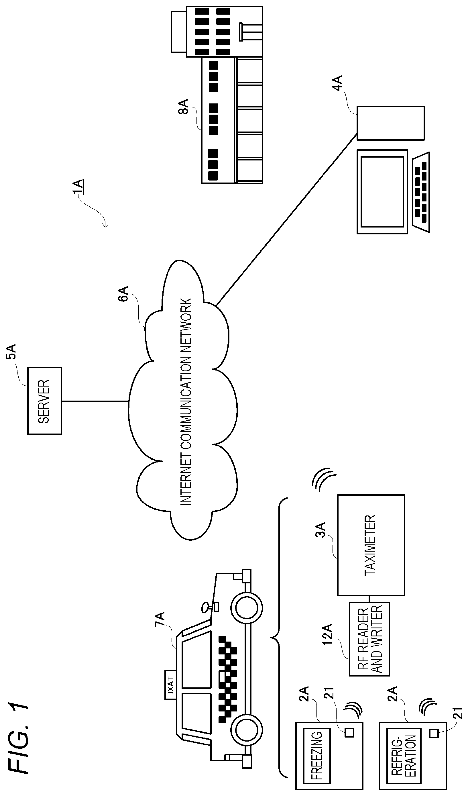
is a configuration diagram of a cooling system as a cooling and warming system of the present invention in a first embodiment.
is a configuration diagram of a taximeter shown in .
is an external view of the taximeter shown in .
is a configuration diagram of a server shown in .
is a sequence diagram showing operation of the cooling system shown in .
is a configuration diagram of a cooling system as a cooling and warming system of the present invention in a second embodiment.
is a configuration diagram of a register shown in .
is a configuration diagram of a locker management unit shown in .
is a sequence diagram showing operation of the cooling system shown in .
is an explanatory diagram for explaining delivery of a cooling agent in a third embodiment.
is a configuration diagram of a cooling system as a cooling and warming system of the present invention in a third embodiment.
is a configuration diagram of a vehicle-mounted device shown in .
is a sequence diagram showing operation of the cooling system shown in .
DETAILED DESCRIPTION OF EMBODIMENTS
First Embodiment
Specific embodiments related to the present invention will be described below with reference to the drawings.
A cooling system 1 A in the first embodiment is a system in which a cooling box 2 A (cooling and warming box) is mounted on a taxi vehicle 7 A (vehicle), which is an example of a commercial vehicle, so that a usage fee can be added to a fare for a passenger using the cooling box 2 A. The cooling system 1 A in the first embodiment is also a system capable of ordering and instructing replacement of the cooling agent accommodated in the cooling box 2 A.
The cooling system 1 A of the present embodiment includes the cooling box 2 A and a taximeter 3 A mounted on the taxi vehicle 7 A, a center terminal 4 A installed in a freezing center 8 A (depository), and a server 5 A (ordering unit, calculation unit) capable of communicating with the taximeter 3 A and the center terminal 4 A via the Internet communication network 6 A.
Examples of the cooling box 2 A include a cooling box for refrigeration and a cooling box for freezing. The cooling box 2 A for refrigeration is a box capable of setting a temperature inside the box to 0° C. to 10° C. (refrigeration temperature range) without a power source by using a cooling agent such as dry ice or a cooling gel. The cooling box 2 A for freezing is a box capable of setting the temperature inside the box to −15° C. or lower (freezing temperature range) without a power source by using a cooling agent such as dry ice or a cooling gel.
Each cooling box 2 A is attached with an sensor-equipped RF tag 21 (first sensor, second sensor). The sensor-equipped RF tag 21 includes a built-in sensor that detects the temperature inside the box, a temperature of the cooling agent, humidity, position, vibration, and an atmosphere composition inside the box, and a built-in memory, and periodically records information of the sensor in the memory. The temperature range (freezing or refrigeration) is recorded in advance in the memory. The sensor-equipped RF tag 21 can read the information recorded in the memory in a non-contact manner by wirelessly communicating with an RF reader and writer 12 A connected to the taximeter 3 A. For example, the RF reader and writer 12 A reads the temperature range (freezing or refrigeration), temperature inside the box, temperature of the cooling agent, humidity, position, vibration, and atmosphere composition inside the box periodically recorded in the memory of the sensor-equipped RF tag 21 as box information and outputs the box information to the taximeter 3 A.
The taximeter 3 A is owned by a taxi company. The taximeter 3 A is mounted on the taxi vehicle 7 A and calculates the fare. The taximeter 3 A sends the box information recorded in the memory of the sensor-equipped RF tag 21 read by the RF reader and writer 12 A to the server 5 A. As shown in , the taximeter 3 A includes an operation unit 31 A, an input unit 32 A, a communication unit 33 A, a GPS receiver 34 A (second sensor), a display unit 35 A, a printing unit 36 A, and a control unit 37 A.
The operation unit 31 A includes various buttons 311 A (see ) such as a vacant button, an occupied button, and a payment button. The operation unit 31 A is an operation unit for allowing a taxi driver to input a state of the taxi vehicle 7 A (whether the taxi vehicle 7 A is vacant or occupied, or the taxi vehicle 7 A arrives at a destination and payment is made). In the present embodiment, the operation unit 31 A includes a freezing button 312 A indicating use of the cooling box for freezing, and a refrigeration button 313 A indicating use of the cooling box for refrigeration.
The input unit 32 A is connected to a speed sensor 9 A, an acceleration sensor 10 A, and a vibration sensor 11 A, and a speed, an acceleration, and vibration detected by the speed sensor 9 A, the acceleration sensor 10 A, and the vibration sensor 11 . A are input to the input unit 32 A. The communication unit 33 A includes a circuit, an antenna, or the like for connecting to the Internet communication network 6 A. As is well known, the GPS receiver 34 A receives radio waves oscillated from a plurality of global positioning system (GPS) satellites, acquires a current position, and outputs the current position to the control unit 37 A described later. As shown in , the display unit 35 A displays the above fare and the temperature inside the storage of the cooling box 2 A used by the passenger. When a printing button (not shown) is pressed, the printing unit 36 A prints and outputs a receipt indicating the fare.
The control unit 37 A includes a central processing unit (CPU) provided with a memory such as a random access memory (RAM) or a read only memory (ROM), and controls the entire taximeter 3 A. The control unit 37 A calculates the fare when the occupied button, which is one of the buttons 311 A, is pressed. When the freezing button 312 A or the refrigeration button 313 A is pressed, the control unit 37 A adds the usage fee of the cooling box 2 A for freezing or refrigeration to the fare. On the receipt printed by the printing unit 36 A, an average temperature in the used cooling box 2 A is described. The control unit 37 A displays the temperature inside the cooling box 2 A for freezing or refrigeration read by the RF reader and writer 12 A on the display unit 35 A when the freezing button 312 A or the refrigeration button 313 A is pressed. The control unit 37 A controls the communication unit 33 A to periodically send the box information read from the sensor-equipped RF tag 21 by the RF reader and writer 12 A and vehicle information to the server 5 A. The vehicle information is information acquired by the taximeter 3 A, and includes, for example, the position acquired from the GPS receiver 34 A, and the speed, acceleration, and vibration acquired from the speed sensor 9 A, acceleration sensor 10 A, and vibration sensor 11 A.
The center terminal 4 A is a terminal installed in the freezing center 8 A and includes a PC. The freezing center 8 A includes a large-scale freezing facility for freezing the cooling agent, and deposits the frozen cooling agent. The freezing center 8 A collects the used (unfrozen) cooling agent collected from the taxi vehicle 7 A, freezes the cooling agent again by the freezing facility, and deposits the frozen cooling agent. The center terminal 4 A communicates with the server 5 A, which will be described later, to receive an order for replacement of the cooling agent.
The server 5 A is owned by an operating company that operates the cooling system 1 A. As shown in , the server 5 A includes a communication unit 51 A, a database (DB) 52 A, and a control unit 53 A.
The communication unit 51 A includes a circuit or the like for connecting to the Internet communication network 6 A. The DB 52 A stores a position of the freezing center 8 A, and the box information and the vehicle information sent from the taximeter 3 A. The control unit 53 A includes a CPU provided with a memory such as an RAM or an ROM, and controls the entire server 5 A. The control unit 53 A performs ordering for replacement of the cooling agent based on the temperature inside the cooling box 2 A and the temperature of the cooling agent among the box information received from the taximeter 3 A.
Next, operation of the cooling system 1 A having the above configuration will be described with reference to . The box information is periodically sent from the sensor-equipped RF tag 21 provided in the cooling box 2 A to the taximeter 3 A (S 1 ). The taximeter 3 A periodically adds driver information indicating information of a driver to the box information and the vehicle information and then sends to the server 5 A (S 2 ). The server 5 A calculates a maintenance time during which the temperature inside the cooling box 2 A is maintained within the freezing temperature range or the refrigeration temperature range from the temperature inside the box and the temperature of the cooling agent included in the box information. When the maintenance time is within a predetermined value, the server 5 A searches the freezing center 8 A around the current position of the taxi vehicle 7 A based on the position information included in the box information and the vehicle information. The server 5 A sends order information for the replacement of the cooling agent to the center terminal 4 A installed in the searched freezing center 8 A (S 3 ). The server 5 A includes the driver information of the driver who performs the replacement to the order information.
When receiving the order information for the replacement of the cooling agent, the center terminal 4 A confirms stock and sends a state of the stock to the server 5 A (S 4 ). In a case of in stock, the server 5 A sends a reservation confirmation request to the center terminal 4 A (S 5 ). When receiving the reservation confirmation request, the center terminal 4 A confirms a reservation and sends that the reservation is confirmed to the server 5 A ( 56 ). When receiving the confirmed reservation, the server 5 A sends a location of the freezing center 8 A where the ordering for the replacement of the cooling agent is performed with respect to the taximeter 3 A (S 7 ).
In addition to the communication with the server 5 A, the taximeter 3 A adds the usage fee of the cooling box 2 A to the fare when the freezing button 312 A or the refrigeration button 313 A is pressed. When the printing button (not shown) is pressed, the taximeter 3 A prints the receipt indicating the fare including the usage fee of the cooling agent, and also prints the average temperature inside the cooling box 2 A.
According to the above embodiment, the sensor-equipped RF tag 21 detects the temperature inside the cooling box 2 A and the temperature of the cooling agent. The server 5 A performs the ordering for the cooling agent based on the detection result of the sensor-equipped RF tag 21 . As a result, it is possible to perform the ordering management of the cooling agent.
According to the above embodiment, the sensor-equipped RF tag 21 or the GPS receiver 34 A detects the position of the taxi vehicle 7 A on which the cooling box 2 A is mounted. The server 5 A performs the ordering in the freezing center 8 A in a location based on the detection result of the sensor-equipped RF tag 21 or the GPS receiver 34 A. As a result, the cooling agent can be ordered from the freezing center 8 A near a location where effect of the cooling agent is expired.
According to the above embodiment, the server 5 A sends the location of the freezing center 8 A where the ordering is performed to the taximeter 3 A and notifies the location to the taxi vehicle 7 A. As a result, the taxi vehicle 7 A side can know the location of the freezing center 8 A where the cooling agent can be replaced.
According to the above embodiment, the server 5 A calculates the maintenance time during which the temperature inside the cooling box 2 A is maintained within a predetermined temperature range based on the detection result of the sensor-equipped RF tag 21 , and performs the ordering based on the calculated maintenance time. As a result, the cooling agent can be replaced while the temperature inside the cooling box 2 A is within the predetermined temperature range.
According to the above embodiment, the temperature inside the cooling box 2 A detected by the sensor-equipped RF tag 21 is displayed on the taximeter 3 A. As a result, the taxi driver and the passenger can know the temperature inside the cooling box 2 A, and can manage the temperature inside the cooling box 2 A.
According to the above embodiment, when the cooling box 2 A is used, the taximeter 3 A adds the usage fee of the cooling box 2 A to a taxi fee (fare). As a result, it is possible to earn the usage fee of the cooling box 2 A.
According to the above embodiment, the printing unit 36 A prints a receipt describing the average temperature in the cooling box 2 A. As a result, the passenger who pays the usage fee of the cooling box 2 A can know the average temperature inside the used cooling box 2 A.
According to the above embodiment, the box information is sent to the server 5 A via the taximeter 3 A, but the present invention is not limited thereto. The box information may also be sent directly from the cooling box 2 A to the server 5 A. Instead of the taximeter 3 A, the box information may also be sent to the server 5 A via a digital tachograph or other communication terminals.
According to the above embodiment, the position of the taxi vehicle 7 A is detected by both the sensor-equipped RF tag 21 and the GPS receiver 34 A, but the present invention is not limited thereto. It suffices if the position can be detected by either the sensor-equipped RF tag 21 or the GPS receiver 34 A.
According to the above embodiment, the taxi vehicle 7 A is described as an example of a commercial vehicle, but the present invention is not limited thereto. The present invention may also be applied to a commercial vehicle such as a bus.
Second Embodiment
Next, the second embodiment will be described with reference to to 9 . A cooling system 1 B in the second embodiment is a system in which a cooling box 2 B is accommodated in a locker 7 B and a shopper can use the locker 7 B as a freezing locker or a refrigeration locker. The cooling system 1 B in the second embodiment is also a system capable of performing ordering for replacement of a cooling agent accommodated in the cooling box 2 B.
The cooling system 1 B of the present embodiment includes the cooling box 2 B accommodated in each of a plurality of lockers 7 B, a register 3 B (use request unit), a locker management unit 4 B that manages the lockers 7 B, a center terminal 5 B installed in a freezing center 11 B, and a server 6 B (rental management unit) capable of communicating with the locker management unit 4 B and the center terminal 5 B via the Internet communication network 8 B.
The locker 7 B is installed in, for example, a large shopping center with a supermarket, and accommodates a purchased product purchased by a shopper 9 B and temporarily deposits the purchased product. Since the cooling box 2 B is the same as the cooling box 2 A described in the first embodiment, detailed description thereof will be omitted here.
Product information and a sales price of the purchased product is input to the register 3 B, and the register 3 B sums up input purchase amounts. As shown in , the register 3 B includes a barcode reader 31 B, an operation unit 32 B, a display unit 33 B, a BT communication unit 34 B, a LAN communication unit 35 B, and a control unit 36 B. The barcode reader 31 B reads a barcode attached to a product and inputs product information and a purchase amount. The operation unit 32 B can perform various kinds of operation such as a use request for the locker 7 B. The display unit 33 B displays a total purchase amount and the like. The BT communication unit 34 B uses, for example, the Bluetooth (registered trademark), and includes a circuit for wirelessly communicating with a mobile terminal 10 B such as a smartphone owned by the shopper 9 B. The LAN communication unit 35 B includes a circuit for communicating with the locker management unit 4 B via a LAN line or the like. The control unit 36 B includes a CPU provided with a memory such as an RAM or an ROM, and controls the entire register 3 B.
As shown in , the locker management unit 4 B includes a display unit 41 B, an operation unit 42 B, a LAN communication unit 43 B, a communication unit 44 B, a QR code (registered trademark) reader 45 B, an RF reader and writer 46 B, and a control unit 47 B. As shown in , the display unit 41 B is attached to the locker 7 B, and displays guidance on a locker usage procedure to the shopper 9 B who uses the locker 7 B. In the present embodiment, the operation unit 42 B adopts a touch panel integrated with the display unit 41 B. The LAN communication unit 43 B includes a circuit for communicating with the register 3 B via a LAN line or the like. The communication unit 44 B includes a circuit for connecting to the Internet: communication network 8 B.
As shown in , the QR code reader 45 B is attached to the display unit 41 B, reads a QR code (key information) displayed on the mobile terminal 10 B of the shopper 9 B, and outputs the QR code (key information) to the control unit 47 B. The control unit 47 B includes a CPU provided with a memory such as an RAM or an ROM, and controls the entire locker management unit 4 B. The control unit 47 B is connected to a lock unit 71 B that locks and unlocks the locker 7 B, and controls the lock and unlock of the locker 7 B.
Since the center terminal 5 B is a terminal installed in the freezing center 11 B as in the first embodiment and is the same as the center terminal 4 A described in the first embodiment, detailed description thereof will be omitted here. Since the server 6 B has the same configuration as the server 5 A described in the first embodiment, detailed description thereof will be omitted here.
Next, operation of the cooling system 1 B having the above configuration will be described with reference to . The box information is periodically sent from the sensor-equipped RF tag 21 provided in the cooling box 2 B to the locker management unit 4 B (S 11 ). The locker management unit 4 B periodically sends the box information to the server 6 B (S 12 ). The server 6 B sends the order information for the replacement of the cooling agent to the center terminal 5 B based on a box temperature, the temperature of the cooling agent, and the state of stock of the cooling agent in the freezing center 11 B included in the box information sent from the locker management unit 4 B. When receiving the order information for the replacement of the cooling agent, the center terminal 5 B arranges to deliver the ordered cooling agent to a store where the locker management unit 4 B is installed.
The shopper 9 B operates his or her own mobile terminal 10 B in advance to register use of the locker. Specifically, personal information such as a name, address, telephone number, and e-mail address of the shopper 9 B is sent from the mobile terminal 10 B to the server 6 B (S 14 ). The server 6 B assigns an ID to each piece of personal information and sends the assigned ID to the mobile terminal 10 B (S 15 ). When receiving the ID, the immobile terminal 10 B can display a barcode (or a QR code) from which the ID can be read. The shopper 9 B pays for the product at the register 3 B when the product is purchased. In this case, a cashier reads a barcode of the product with the barcode reader 31 B of the register 3 B and inputs the product information and the sales price of the purchased product. The register 3 B sums up the input sales price and displays on the display unit 33 B.
When reading of the barcode is completed, the cashier asks the shopper 9 B whether to use the locker 7 B accommodating the cooling box 2 B. When using the shopper 9 B, the cashier operates the operation unit 32 B to perform a use request operation for the locker 7 B, and asks the shopper 9 B to display the barcode from which the ID can be read on the mobile terminal 10 B. The shopper 9 B operates the mobile terminal 10 B to display the barcode from which the ID can be read on the mobile terminal 10 B. The cashier reads the barcode displayed on the mobile terminal 10 B with the barcode reader 31 B. When the register 3 B inputs the ID read by the barcode reader 31 B after the use request operation is performed, the register 3 B sends the use request with the ID to the locker management unit 4 B (S 16 ).
In this case, the register 3 B also sends information of a temperature range (information of freezing or refrigeration) corresponding to the input product information to the locker management unit 4 B. For example, the register 3 B sends the information of refrigeration if the input product information is a refrigerated food, and sends the information of freezing if the input product information is a frozen food.
When receiving the use request, the locker management unit 4 B sends the ID assigned to the use request to the server 6 B and performs verification (S 17 ). The server 6 B verifies whether the personal information corresponding to the received ID is registered, and sends a result to the locker management unit 4 B (S 17 ). If the verification is successful, the locker management unit 4 B sends the key information of the available locker 7 B to the register 3 B (S 18 ). In this case, the locker management unit 4 B sends the key information of the locker 7 B accommodating the cooling box 2 B for freezing if the use request is assigned with the information of freezing, and sends the key information of the locker 7 B accommodating the cooling box 2 B for refrigeration if the use request is assigned with the information of refrigeration.
When receiving the key information, the register 3 B sends the key information to the mobile terminal 10 B by BT communication (S 19 ). As a result, a QR code (or a barcode) from which the key information can be read can be displayed on the mobile terminal 10 B. The locker management unit 4 B sends to the server 6 B that the cooling box 2 B accommodated in the locker 7 B, which is unlocked by the sent key information, is rented. The server 6 B performs rental management of the cooling box 2 B based on this rental information.
When the shopper 9 B operates the locker management unit 4 B, the control unit 47 B of the locker management unit 4 B displays on the display unit 41 B that “Please display the QR code on the mobile phone and have the QR code read”. The shopper 9 B displays the QR code on the mobile terminal 10 B and holds the mobile terminal 10 B up to the QR code reader 45 B. The QR code reader 45 B inputs the key information read from the QR code to the control unit 47 B. The control unit 47 B controls the lock unit 71 B of the locker 7 B corresponding to the key information read by the QR code reader 45 B to unlock the locker 7 B. When the locker 7 B is unlocked by the locker management unit 4 B, a door is automatically opened. When the shopper 9 B accommodates the purchased product in the cooling box 2 B accommodated in the locker 7 B and closes the door, the locker management unit 4 B locks the lock unit 71 B and locks the locker 7 B. In this case, the locker management unit 4 B manages the locked locker 7 B as being in use.
When the shopper 9 B who shops at another store or finishes eating operates the locker management unit 4 B again, the control unit 47 B of the locker management unit 4 B similarly displays on the display unit 41 B that “Please display the QR code of the key information on the mobile phone and make the QR code read by the QR code reader”. The shopper 9 B displays the QR code on the mobile terminal 10 B and have the QR code reader 45 B to read the QR code. As a result, the control unit 47 B controls the lock unit 71 B of the locker 7 B corresponding to the key information read by the QR code reader 45 B to unlock the locker 7 B. When the shopper 9 B takes out the product from the cooling box 2 B accommodated in the locker 7 B and closes the door, the locker management unit 4 B locks the lock unit 71 B and locks the locker 7 B. In this case, the shopper 9 B may take out the cooling box 2 B from the locker 7 B and take the cooling box 2 B home.
According to the above embodiment, the locker management unit 4 B manages the availability of the plurality of lockers 7 B accommodating the cooling box 2 B. The register 3 B requests use of the locker 7 B with respect to the locker management unit 4 B. The locker management unit 4 B sends the key information for unlocking the available locker 7 B to the register 3 B. As a result, it is possible to manage the cooling agent accommodated in the locker 7 B.
According to the above embodiment, the register 3 B sends a rental request for the cooling box 2 B accommodated in the locker 7 B that can be unlocked by the received key information to the server 6 B, and the server 6 B manages the rental of the cooling box 2 B based on the rental request. As a result, it is possible to manage the rental of the cooling box 2 B.
According to the above embodiment, the register 3 B sends the information of freezing or refrigeration corresponding to the input product information to the locker management unit 4 B. As a result, it is possible to use the locker 7 B set to a temperature corresponding to the product information of the purchased product.
According to the above embodiment, the key information is sent from the register 3 B to the mobile terminal 10 B. As a result, the locker 7 B can be unlocked by the mobile terminal 10 B of the shopper 9 B.
According to the above embodiment, the register 3 B functions as a use request unit and sends the use request for the locker 7 B and the rental request for the cooling box 2 B, but the present invention is not limited thereto. The mobile terminal 10 B owned by the shopper 9 B and the locker management unit 4 B may communicate with each other via the Internet communication network 8 B, and the mobile terminal 10 B may also make the use request for the locker 7 B and the rental request for the cooling box 2 B.
According to the above embodiment, the register 3 B determines whether the product is frozen or refrigerated based on the product information, but the present invention is not limited thereto. The register 3 B may send the product information to the locker management unit 4 B and determine whether the product is frozen or refrigerated based on the product information received by the locker management unit 4 B.
According to the above embodiment, the key information is sent from the register 3 B to the mobile terminal 10 B, but the present invention is not limited thereto. The register 3 B may print the QR code from which the key information can be read and give the QR code to the shopper 9 B.
According to the above embodiment, the box information is sent to the server 6 B via the locker management unit 4 B, but the present invention is not limited thereto. The box information may also be sent directly from the cooling box 2 B to the server 6 B.
According to the above embodiment, the register 3 B includes the built-in LAN communication unit 43 B that communicates with the locker management unit 4 B, but the present invention is not limited thereto. The LAN communication unit 43 B may be externally connected to the register 3 B.
Third Embodiment
Next, the third embodiment will be described with reference to to 13 . As shown in a cooling system 1 C in the third embodiment is a system capable of delivering a cooling agent from a freezing center 8 C to a transport warehouse 7 C (depository) which is a base of a delivery vehicle 15 C (vehicle) such as a truck.
As shown in , the cooling system 1 C includes a cooling box 2 C and a vehicle-mounted device 3 C mounted on the delivery vehicle 15 C, a warehouse terminal 4 C installed in the transport warehouse 7 C, a center terminal 5 C installed in the freezing center 8 C, and a server 6 C capable of communicating with the vehicle-mounted device 3 C, the warehouse terminal 4 C and the center terminal 5 C via the Internet communication network 9 C.
Since the cooling box 2 C has the same configuration as the cooling boxes 2 A and 2 B described in the above first and second embodiments, detailed description thereof will be omitted here. In the present embodiment, the cooling box 2 C is managed in the transport warehouse 7 C and mounted on the delivery vehicle 15 C. The sensor-equipped RF tag 21 attached to the cooling box 2 C wirelessly communicates with an RF reader and writer 10 C and an RF reader and writer 11 C connected to the vehicle-mounted device 3 C and the warehouse terminal 4 C, which will be described later, and can read information recorded in the memory in a non-contact manner. For example, the RF reader and writer 10 C and the RF reader and writer 11 C read the temperature range (freezing or refrigeration), temperature inside the box, temperature of the cooling agent, humidity, position, vibration, and atmosphere composition inside the box periodically recorded in the memory of the sensor-equipped RF tag 21 as box information and outputs the box information to the vehicle-mounted device 3 C and the warehouse terminal 4 C.
The vehicle-mounted device 3 C includes, for example, a digital tachograph mounted on the delivery vehicle 15 C. The vehicle-mounted device 3 C is owned by a carrier. The vehicle-mounted device 3 C is mounted on the delivery vehicle 15 C and collects traveling information. The vehicle-mounted device 3 C sends the box information recorded in the memory of the sensor-equipped RF tag 21 read by the RF reader and writer 11 C to the server 6 C. As shown in , the vehicle-mounted device 3 C includes an operation unit 31 C, an input unit 32 C, a communication unit 33 C, a GPS receiver 34 C, a display unit 35 C, and a control unit 36 C.
The operation unit 31 C includes various buttons for operating and inputting work contents such as unloading, loading, and resting. The input unit 32 C is connected to a speed sensor, an acceleration sensor, and a vibration sensor, and a speed, an acceleration, and vibration detected by the speed sensor, the acceleration sensor, and the vibration sensor are input to the input unit 32 C. The communication unit 33 C includes a circuit, an antenna, or the like for connecting to the Internet communication network 9 C. As is well known, the GPS receiver 34 C receives radio waves oscillated from a plurality of GPS satellites, acquires a current position, and outputs the current position to the control unit 36 C described later.
The control unit 36 C includes a CPU provided with a memory such as an RAM or an ROM, and controls the entire vehicle-mounted device 3 C. The control unit 36 C controls the communication unit 33 C to periodically send the box information read from the sensor-equipped RF tag 21 by the RF reader and writer 11 C and vehicle information to the server 6 C. The vehicle information is information acquired by the vehicle-mounted device 3 C, and includes, for example, the position acquired from the GPS receiver 34 C, and the speed, acceleration, and vibration acquired from the speed sensor, acceleration sensor, and vibration sensor.
The warehouse terminal 4 C is a terminal installed in the transport warehouse 7 C and includes a PC. A small freezing facility is installed in the transport warehouse 7 C, and the cooling agent is stored in the freezing facility. The transport warehouse 7 C may not include the freezing facility. The RF reader and writer 10 C is connected to the warehouse terminal 4 C. The RF reader and writer 10 C reads the information recorded in the memory of the sensor-equipped RF tag 21 provided in the cooling box 2 C accommodated in the transport warehouse 7 C, and outputs the information to the warehouse terminal 4 C. The warehouse terminal 4 C sends the box information output from the RF reader and writer 10 C to the server 6 C. The warehouse terminal 4 C manages the stock of the frozen cooling agent and sends stock information to the server 6 C.
The center terminal 5 C is a terminal installed in the freezing center 8 C and includes a PC. The freezing center 8 C includes a large-scale freezing facility for freezing the cooling agent, and deposits the frozen cooling agent. The freezing center 8 C collects the used (unfrozen) cooling agent collected from the transport warehouse 7 C, freezes the cooling agent again by the freezing facility, and deposits the frozen cooling agent. The center terminal 5 C communicates with the server 6 C, which will be described later, to receive an order for replacement of the cooling agent.
The server 6 C is owned by an operating company that operates the cooling system 1 C. Since the server 6 C has the same configuration as the server 5 A described in the first embodiment, detailed description thereof will be omitted here.
Next, operation of the cooling system 1 C having the above configuration will be described with reference to . The box information is sent from the sensor-equipped RF tag 21 provided in the cooling box 2 C mounted on the delivery vehicle 15 C to the vehicle-mounted device 3 C (S 31 ). The vehicle-mounted device 3 C periodically assigns an ID of the delivery vehicle 15 C to the box information and the vehicle information and sends the box information and the vehicle information to the server 6 C (S 32 ). The server 6 C calculates a maintenance time during which the temperature of the cooling box 2 C is maintained within the freezing temperature range or the refrigeration temperature range from the temperature of the box and the temperature of the cooling agent included in the box information. When the maintenance time is within a predetermined value, the server 6 C searches the transport warehouse 7 C around the current position of the delivery vehicle 15 C based on the position information included in the box information and the vehicle information. The server 6 C sends the order information for the replacement of the cooling agent to the warehouse terminal 4 C installed in the searched transport warehouse 7 C (S 33 ). The server 6 C includes the ID of the delivery vehicle 15 C which performs the replacement in the order information.
When receiving the order information for the replacement of the cooling agent, the warehouse terminal 4 C confirms the stock and sends a state of the stock to the server 6 C. When receiving a state of in stock, the server 6 C sends a reservation confirmation request to the warehouse terminal 4 C. When receiving the reservation confirmation request, the warehouse terminal 4 C confirms a reservation and sends that the reservation is confirmed to the server 6 C. When receiving the confirmed reservation, the server 6 C sends a location of the transport warehouse 7 C where the ordering for the replacement of the cooling agent is performed with respect to the vehicle-mounted device 3 C (S 34 ).
The box information is sent from the sensor-equipped RF tag 21 provided in the cooling box 2 C in the transport warehouse 7 C to the warehouse terminal 4 C. The warehouse terminal 4 C periodically sends the box information to the server 6 C. The warehouse terminal 4 C manages the stock of the cooling agent, and sends the stock and shortage information of the cooling agent to the server 6 C as warehouse information. The server 6 C sends the order information for the replacement of the cooling agent to the center terminal 5 B based on the warehouse information (S 38 ). In this case, the server 6 C sends the order information including a quantity of the cooling agent, a temperature range of the cooling agent, a delivery time of the cooling agent, and the location of the transport warehouse, which is a delivery destination.
When receiving the order information for the replacement of the cooling agent, the center terminal 5 C confirms the stock and sends the state of the stock to the server 6 C. When receiving the state of in stock, the server 6 C sends the reservation confirmation request to the center terminal 5 B. When receiving the reservation confirmation request, the center terminal 5 C confirms a reservation and sends that the reservation is confirmed to the server 6 C. Then, the server 6 C performs ordering with respect to the freezing center 8 C, and sends to the warehouse terminal 4 C that the cooling agent is delivered and collected (S 39 ).
According to the above embodiment, the sensor-equipped RF tag 21 detects the temperature inside the cooling box 2 C and the temperature of the cooling agent, as in the first embodiment. The server 6 C performs the ordering for the cooling agent based on the detection result of the sensor-equipped RF tag 21 . As a result, it is possible to perform the ordering management of the cooling agent.
According to the above embodiment, since the cooling agent can be delivered from the freezing center 8 C to the transport warehouse 7 C, it is not necessary to equip each transport warehouse 7 C with a large-scale freezing facility.
According to the above embodiment, the box information is sent to the server 6 C via, the vehicle-mounted device 3 C and the warehouse terminal 4 C, but the present invention is not limited thereto. The box information may also be sent directly from the cooling box 2 C to the server 6 C.
According to the above embodiment, the server 6 C sends the order information to the warehouse terminal 4 C so that the replacement of the cooling agent mounted on the delivery vehicle 15 C is performed in the transport warehouse 7 C, but the present invention is not limited thereto. If the freezing center 8 C is near the delivery vehicle 15 C, the server 6 C may send the order information to the center terminal 5 C so that the cooling agent can be replaced at the freezing center 8 C.
According to the above first to third embodiments, the cooling boxes 2 A to 2 C accommodating the cooling agent is used, but the present invention is not limited thereto. Instead of the cooling boxes 2 A to 2 C, or in addition to the cooling boxes 2 A to 2 C, a warming box accommodating a warming agent may be used.
According to an embodiment, a cooling and warming system ( 1 A, 1 B, 1 C) includes:
•
• a first sensor ( 21 ) that is attached to a cooling and warming box ( 2 A, 2 B, 2 C) accommodating a cooling and warming agent and that detects a temperature inside the cooling and warming box ( 2 A, 2 B, 2 C) and a temperature of the cooling and warming agent; and • an ordering unit ( 5 A, 6 B, 6 C) that performs ordering of the cooling and warming agent based on a detection result of the first sensor ( 21 ).
According to the cooling and warming system having a configuration of the above, the first sensor detects the temperature inside the cooling and warming box and the temperature of the cooling and warming agent. The ordering unit performs the ordering for the cooling and warming agent based on the detection result of the first sensor. As a result, it is possible to perform ordering management of the cooling and warming agent.
The cooling and warming system ( 1 A, 1 B, 1 C) may further include:
•
• a second sensor ( 21 , 34 A, 34 C) that detects a position of a vehicle on which the cooling and warming box ( 2 A, 2 B, 2 C) is mounted, in which • the ordering unit ( 5 A, 6 B, 6 C) performs the ordering at a depository ( 7 C, 8 A, 8 C, 1 B) for depositing the cooling and warming agent in a location based on a detection result of the second sensor ( 21 , 34 A, 34 C).
According to the cooling and warming system having a configuration of the above, the second sensor detects the position of the vehicle on which the cooling and warming box is mounted. The ordering unit performs the ordering with respect to a cooling and warming center at a location based on the detection result of the second sensor. As a result, the cooling and warming agent can be ordered from the cooling and warming center near a location where effect of the cooling and warming agent is expired.
In the cooling and warming system ( 1 A, 1 B, 1 C), the ordering unit ( 5 A, 6 B, 6 C) may notify the vehicle of a location of the depository where the ordering is performed.
According to the cooling and warming system having a configuration of the above, the ordering unit notifies the vehicle of the location of the cooling and warming center where the ordering is performed. As a result, the vehicle side can know the location of the cooling and warming center where the cooling and warming agent can be replaced.
The cooling and warming system ( 1 A, 1 B, 1 C) may further include:
•
• a calculation unit ( 5 A, 6 C) that calculates a maintenance time during which the temperature inside the cooling and warming box ( 2 A, 2 B, 2 C) is maintained within a predetermined temperature range based on the detection result of the first sensor ( 21 ), in which • the ordering unit ( 5 A, 6 B, 6 C) performs the ordering based on the maintenance time calculated by the calculation unit ( 5 A, 6 C).
According to the cooling and warming system having a configuration of the above, the calculation unit calculates the maintenance time during which the temperature inside the cooling and warming box is maintained within a predetermined temperature range based on the detection result of the first sensor, and the ordering unit performs the ordering based on the maintenance time calculated by the calculation unit. As a result, the cooling and warming agent can be replaced while the temperature inside the cooling and warming box is within the predetermined temperature range.
The cooling and warming system ( 1 A) may further include:
•
• a taximeter ( 3 A) that calculates a taxi fee, in which • the taximeter ( 3 A) displays the temperature inside the cooling and warming box ( 2 A) detected by the first sensor ( 21 ).
According to the cooling and warming system having configurations of the above, the temperature inside the cooling and warming box detected by the first sensor is displayed on the taximeter. As a result, a taxi driver and a passenger can know the temperature inside the cooling and warming box, and can manage the temperature inside the cooling and warming box.
In the cooling and warming system ( 1 A), when the cooling and warming box ( 2 A) is used, the taximeter ( 3 A) may add a usage fee of the cooling and warming box ( 2 A) to the taxi fee.
According to the cooling and warming system having a configuration of the above, when the cooling and warming box is used, the taximeter adds the usage fee of the cooling and warming box to the taxi fee. As a result, it is possible to earn the usage fee of the cooling and warming box.
In the cooling and warming system ( 1 A), the taximeter ( 3 A) may include a printing unit ( 36 A) that prints a receipt indicating the taxi fee, and
when the cooling and warming box ( 2 A) is used, the printing unit ( 36 A) prints an average temperature inside the cooling and warming box ( 2 A).
According to the cooling and warming system having a configuration of the above, the printing unit prints the receipt in which the average temperature inside the cooling and warming box is described. As a result, a passenger who pays the usage fee of the cooling and warming box can know the average temperature inside the used cooling and warming box.
The cooling and warming system ( 1 B), may further include:
•
• a locker management unit ( 4 B) that manages availability of a plurality of lockers ( 7 B) accommodating the cooling and warming box ( 2 B); and • a use request unit ( 3 B) that requests use of the locker ( 7 B) with respect to the locker management unit ( 4 B), in which
when receiving a use request for the locker ( 7 B) from the use request unit ( 3 B), the locker management unit ( 4 B) sends key information for unlocking an available locker ( 7 B) to the use request unit ( 3 B).
According to the cooling and warming system having configurations of the above, the locker management unit manages the availability of the plurality of lockers accommodating the cooling and warming box. The use request unit requests the use of the locker with respect to the locker management unit. The locker management unit sends the key information for unlocking the available locker to the use request unit. As a result, it is possible to manage the cooling and warming agent accommodated in the locker.
The cooling and warming system ( 1 B, 1 C) may further include:
•
• a rental management unit ( 6 B) that manages rental of the cooling and warming box ( 2 A, 2 B, 2 C), in which • the use request unit ( 3 B) sends a rental request for the cooling and warming box ( 2 A, 2 B, 2 C) accommodated in the locker ( 7 B) that can be unlocked by the received key information to the rental management unit ( 6 B), and • the rental management unit ( 6 B) manages the rental of the cooling and warming box ( 2 A, 2 B, 2 C) based on the rental request.
According to the cooling and warming system having a configuration of the above, the use request unit sends the rental request for the cooling and warming box accommodated in the locker that can be unlocked by the received key information to the rental management unit, and the rental management unit manages the rental of the cooling and warming box based on the rental request. As a result, it is possible to manage the rental of the cooling and warming box.
The cooling and warming system ( 1 B) may further include:
•
• a register ( 3 B) to which product information and a sales price of a purchased product is input and that sums up input purchase amounts, in which • the locker management unit ( 4 B) manages the availability of the lockers ( 7 B) set to a plurality of types of temperature ranges, and • the use request unit ( 3 B) is built in or connected to the register ( 3 B), and requests use of a locker ( 7 B) set to a temperature range corresponding to the input product information.
According to the cooling and warming system having a configuration of the above, it is possible to use the locker set to the temperature corresponding to the product information of the purchased product.
The cooling and warming system ( 1 B) may further include:
•
• a register ( 3 B) to which product information and a sales price of a purchased product is input and that sums up input purchase amounts, in which • the locker management unit ( 4 B) manages the availability of the lockers ( 7 B) set to a plurality of types of temperature ranges, • the use request unit ( 3 B) is built in or connected to the register ( 3 B), and sends the input product information to the locker management unit ( 4 B), and • the locker management unit ( 4 B) sends key information of the locker ( 7 B) set to the temperature range corresponding to the sent product information to the use request unit ( 3 B).
According to the cooling and warming system having a configuration of the above, it is possible to use the locker set to the temperature corresponding to the product information of the purchased product.
In the cooling and warming system ( 1 B), when receiving the key information from the locker management unit ( 4 B), the use request unit ( 3 B) may send the key information to a mobile terminal ( 10 B) of a shopper.
According to the cooling and warming system having a configuration in the above, the locker can be unlocked by the mobile terminal of the shopper.
A cooling and warming system ( 1 A) may include:
•
• a first sensor ( 21 ) that is attached to a cooling and warming box ( 2 A) accommodating a cooling and warming agent and that detects a temperature inside the cooling and warming box ( 2 A) and a temperature of the cooling and warming agent; and • a taximeter ( 3 A) that calculates a taxi fee of a taxi vehicle on which the cooling and warming box ( 2 A) is mounted, in which • the taximeter ( 3 A) displays the temperature inside the cooling and warming box ( 2 A) detected by the first sensor ( 21 ).
According to the cooling and warming system having configurations of the above, the temperature inside the cooling and warming box detected by the first sensor is displayed on the taximeter. As a result, a taxi driver and a passenger can know the temperature inside the cooling and warming box, and can manage the temperature inside the cooling and warming box.
A cooling and warming system ( 1 B) may include:
•
• a locker management unit ( 4 B) that manages availability of a plurality of lockers ( 7 B) accommodating a cooling and warming box ( 2 C) in which a cooling and warming agent is accommodated; and • a use request unit ( 3 B) that requests use of the locker ( 7 B) with respect to the locker management unit ( 4 B), in which
when receiving a use request for the locker ( 7 B) from the use request unit ( 3 B), the locker management unit ( 4 B) sends key information for unlocking an available locker ( 7 B) to the use request unit ( 3 B).
According to the cooling and warming system having configurations of the above, the locker management unit manages the availability of the plurality of lockers accommodating the cooling and warming box. The use request unit requests the use of the locker with respect to the locker management unit. The locker management unit sends the key information for unlocking the available locker to the use request unit. As a result, it is possible to manage the cooling and warming agent accommodated in the locker.
According to an embodiment, it is possible to achieve a cooling and warming system capable of managing a cooling and warming box, such as ordering management of a cooling and warming agent.
Although the present invention is described in detail with reference to the specific embodiments, it is apparent to those skilled in the art that various changes and modifications can be made without departing from the spirit and scope of the present invention.
Figures (11)
Citations
This patent cites (16)
- US10731919
- US2019/0372449
- US2020/0366180
- US2021/0311494
- US102542833
- US110494388
- US3531354
- US2003-237457
- US2004-070911
- US2004-251508
- US2010-073102
- US2012-032087
- US2018055401
- US2019053526
- USWO-2018075157
- US2018-155408