Pulp Molded Product Line with Roll Forming Function
Abstract
A pulp molded product line with roll forming function includes a pulp suction device, a hot pressing assembly used to perform hot pressing on a pulp sucked by the pulp suction device to obtain a hot pressed pulp molded product, an edge cutting device used to perform edge cutting on the hot pressed pulp molded product to obtain an unrolled pulp molded product; and a rolling device used to perform radially inwards rolling on the unrolled pulp molded product to obtain a pulp molded product. The advantages of the pulp molded product line with roll forming function are that the waste problem of inconsistent material thickness by rolling can be solved, the raw materials can be saved and the production and processing efficiency can be improved.
Claims (19)
1. A pulp molded product line with roll forming function, comprising: a pulp suction device; a hot pressing assembly, configured to perform hot pressing on a pulp sucked by the pulp suction device to obtain a hot pressed pulp molded product; an edge cutting device, configured to perform edge cutting on the hot pressed pulp molded product obtained after the hot pressing of the hot pressing assembly to obtain an unrolled pulp molded product; and a rolling device, configured to perform radially inwards rolling on the unrolled pulp molded product obtained after the edge cutting of the edge cutting device to obtain a pulp molded product; wherein an annular convex buckle is formed on an inner wall of the pulp molded product obtained after the rolling of the rolling device, and an annular rolling groove corresponding to the annular convex buckle is formed on an outer wall of the pulp molded product; wherein the rolling device comprises: a loading unit, configured to load and convey the unrolled pulp molded product; a rolling unit, comprising a horizontal rotating table; wherein at least one translatable rolling wheel is horizontally slidably connected to an upper surface of the horizontal rotating table, the at least one translatable rolling wheel is connected to a translation driving mechanism and a rotation driving mechanism, the upper surface of the horizontal rotating table is rotatably connected to two rolling moving dies located at a periphery of each translatable rolling wheel and symmetrically distributed with the translatable rolling wheel as a center, a rotation direction of each of the two rolling moving dies is opposite to a rotation direction of the translatable rolling wheel, and rotation speeds of the rolling moving die and the translatable rolling wheel are the same; each rolling moving die corresponds to a rotary pressing-down assembly, each rolling moving die corresponds to a rotary driving mechanism, the rotary driving mechanism is configured to drive the rolling moving die to rotate, the translatable rolling wheel is configured to move close to the rolling moving die, thereby to radially inwards roll the unrolled pulp molded product, and a next unrolled pulp molded product is placed on another rolling moving die; and a take-and-place unit, configured to place the unrolled pulp molded product conveyed by the loading unit on the rolling moving die, and obtain and transfer the rolled pulp molded product out of the rolling unit; and wherein the pulp suction device and the hot pressing assembly are used to transfer the pulp through a first robot; and the edge cutting device and the rolling device are used to transfer the unrolled pulp molded product through a second robot.
13. A pulp molded product line with roll forming function, comprising: a pulp suction device; a hot pressing assembly, configured to perform hot pressing on a pulp sucked by the pulp suction device to obtain a hot pressed pulp molded product; an edge cutting device, configured to perform edge cutting on the hot pressed pulp molded product obtained after the hot pressing of the hot pressing assembly to obtain an unrolled pulp molded product; and a rolling device, configured to perform radially inwards rolling on the unrolled pulp molded product obtained after the edge cutting of the edge cutting device to obtain a pulp molded product, and the rolling device comprises a frame, a horizontally arranged rotating table is disposed on the frame, the rotating table is connected to a rotating power device, a plurality of rolling cavity dies are installed on the rotating table, each of the plurality of rolling cavity dies is rotationally connected to the rotating table and is configured to fix the pulp molded product, the plurality of rolling cavity dies are distributed in a circle, the frame is provided with a support and a lifting power member installed on the support, the lifting power member is connected to a pressing block, the pressing block is rotationally connected to the lifting power member, the rotating power member is configured to drive the rotating table to rotate to thereby make the plurality of rolling cavity dies alternately enter directly below the pressing block, the frame is provided with a lifting seat located under the rotating table and a lifting power device, the lifting power device is configured to drive the lifting seat to lift vertically, the lifting power device is provided with a cavity die rotation power device, the lifting power device is configured to drive the cavity die rotation power device to rise, a clutch connection structure is connected between the cavity die rotation power device and the rolling cavity die directly under the pressing block to realize the rotation of the rolling cavity die, the frame is further provided with a rolling terrace die, the rolling terrace die is relatively distributed with the rolling cavity die directly below the pressing block, the rolling terrace die is connected to a terrace die rotation driving device, and the terrace die rotation driving device is arranged on a translation driving device; wherein an annular convex buckle is formed on an inner wall of the pulp molded product obtained after the rolling of the rolling device, and an annular rolling groove corresponding to the annular convex buckle is formed on an outer wall of the pulp molded product.
Show 17 dependent claims
2. The pulp molded product line with roll forming function according to claim 1 , wherein the number of the rolling unit is two, the two rolling units are linearly distributed front and back at intervals, and the two rolling units are rotatably connected to a frame.
3. The pulp molded product line with roll forming function according to claim 2 , wherein the number of the take-and-place unit is two, one of the two take-and-place units is located above the loading unit, the other take-and-place unit is located above an unloading unit, the one take-and-place unit is configured to place unrolled pulp molded products conveyed by the loading unit on the two rolling units in a one by one way, and the other take-and-place unit is configured to obtain and transfer pulp molded products rolled by the two rolling units to the unloading unit in a one by one way, the loading unit and the unloading unit are distributed in parallel, and the rolling units are located between the loading unit and the unloading unit.
4. The pulp molded product line with roll forming function according to claim 1 , wherein the number of the at least one translatable rolling wheel is multiple, and the multiple translatable rolling wheels are arranged in a row, the rotation driving mechanism is configured to drive the translatable rolling wheels to rotate synchronously, the two rolling moving dies which are symmetrically distributed with the translatable rolling wheel as the center are distributed on the periphery of each translatable rolling wheel, the rolling moving dies are arranged in two rows, the number of the rotary driving mechanism is two, and one of the two rotary driving mechanisms is configured to drive the rolling moving dies located on a same raw to rotate synchronously, and the rotary pressing-down assemblies are distributed in two rows and located on a same row act synchronously.
5. The pulp molded product line with roll forming function according to claim 4 , wherein each rotary pressing-down assembly comprises: a rotating cylinder and a pressing block connected to a rotating telescopic rod of the rotating cylinder, and the pressing block is rotatably connected to the rotating telescopic rod of the rotating cylinder.
6. The pulp molded product line with roll forming function according to claim 4 , wherein the translation driving mechanism comprises a translation plate horizontally and slidably connected with the horizontal rotating table, each translatable rolling wheel is mounted on the translation plate through a connecting shaft and the connecting shaft is rotatably connected with the translation plate, and the horizontal rotating table is provided with a translation power assembly configured to drive the translation plate to move close to the rolling moving die or move facing away from the rolling moving die.
7. The pulp molded product line with roll forming function according to claim 6 , wherein the rotation driving mechanism comprises a linkage synchronous belt wound on two adjacent connecting shafts, one the connecting shaft is connected with a driving motor through an active synchronous belt, and the driving motor is fixed on one of the translation plate and the horizontal rotating table.
8. The pulp molded product line with the roll forming function according to claim 4 , wherein each rotary driving mechanism comprises a rotating synchronous belt wound on rolling rotating shafts connected with the rolling moving dies, the rotating synchronous belt is connected to a rotating servo motor fixed on the horizontal rotating table, and a section of the rotating synchronous belt wound on the rolling rotating shafts is wavy.
9. The pulp molded product line with the roll forming function according to claim 4 , wherein the rotary pressing-down assemblies on one same row and the rotary pressing-down assemblies on the other same column are arranged in a staggered manner.
10. The pulp molded product line with roll forming function according to claim 3 , wherein each take-and-place unit is installed on a gantry bracket, and a camera located at a loading end of the loading unit is arranged on an inner side of two ends of the gantry bracket; the take-and-place unit is connected to a lower side of a top of the gantry bracket through a translation driving device, and the translation driving device is configured to drive the take-and-place unit to translate, thereby to transfer the rolled pulp molded products to the unloading unit.
11. The pulp molded product line with roll forming function according to claim 10 , wherein each take-and-place unit comprises a horizontally arranged triangular block, each corner of a lower surface of the triangular block is connected with an upper connecting block, a lower surface of each upper connecting block is connected with a connecting rod, lower ends of the connecting rods are inwards converged and connected to a lower connecting block, and a lower surface of the lower connecting block is connected with a material taking device.
12. The pulp molded product line with the roll forming function according to claim 1 , wherein the edge cutting device comprises a horizontal rotating table, at least one translatable rotary cutter with circular shape is horizontally and slidably connected to an upper surface of the horizontal rotating table, the translatable rotary cutter with circular shape is connected with a translation driving mechanism and a rotation driving mechanism, the upper surface of the horizontal rotating table is rotatably connected with two rotary cutting moving dies located at a periphery of each translatable rotary cutter with circular shape and symmetrically distributed with the translatable rotary cutter with circular shape as a center, each rotary cutting moving die corresponds to a rotary pressing-down assembly, each rotary cutting moving die corresponds to a rotary driving mechanism, and the rotary driving mechanism is configured to drive the rotary cutting moving die to rotate, the translatable rotary cutter with circular shape moves close to one the rotary cutting moving die to radially inwardly cut a pulp molded product without edge cutting, and a next pulp molded product without edge cutting is placed on another rotary cutting moving die.
14. The pulp molded product line with the roll forming function according to claim 13 , wherein the frame is provided with at least one sensor fixing block located on an outer side of the rotating power device and a position sensor fixed on one of the at least one sensor fixing block, the outer side of the rotating power device is connected with rotating positioning blocks with a number equal to a total number of the plurality of rolling cavity dies, the rotating power device is configured to drive the rotating positioning blocks to rotate synchronously, and when the position sensor is opposite to one of the rotating positioning blocks, it is indicated that one rolling cavity die is located under the pressing block.
15. The pulp molded product line with the roll forming function according to claim 13 , wherein the lifting seat is a rectangular frame, the cavity die rotation power device is a servo motor, the servo motor is located in the rectangular frame, an upper end of the servo motor is fixed to a top side of the rectangular frame, an output shaft of the servo motor upwards penetrates through the top side of the rectangular frame, a Y-shaped sensor is arranged on a top surface of the rectangular frame, the output shaft of the servo motor is sleeved with a linkage plate, a notch is provided on a linkage plate, and when the notch of the linkage plate enters a sensing range of the Y-shaped sensor, it is indicated that the output shaft of the servo motor rotates in place.
16. The pulp molded product line with the roll forming function according to claim 15 , wherein the clutch connecting structure comprises a flat connector arranged at a top of the output shaft of the servo motor, a clutch plate is connected to a lower end of each rolling cavity die, and a flat hole allowing the flat connector to be inserted is formed in a center of the clutch plate; and wherein the rotating power device is a rotary air cylinder, a rotating shaft is connected to the rotating power device, a rotating shaft base sleeved at an upper end of the rotating shaft is arranged on the frame, the rotating table is installed on an end face of the rotating shaft extended to the upper end of the rotating shaft base, a cantilever block is arranged on a side of the rotating shaft base, a support notch is formed in the cantilever block, and the output shaft of the servo motor is snapped in the support notch.
17. The pulp molded product line with the roll forming function according to claim 16 , wherein the rotating table comprises a strip-shaped plate, a middle position of the strip-shaped plate is fixed to an upper end face of the rotating shaft, and the rolling cavity dies are arranged at two ends of an upper surface of the strip-shaped plate respectively; and wherein the two ends of the upper surface of the strip-shaped plate are respectively provided with mounting holes and the rolling cavity dies are rotatably mounted in the mounting holes, the clutch plate is located in the mounting hole, two ends of a lower surface of the strip-shaped plate are respectively provided with two lower plates under the clutch plate, a center of the rotating shaft base is provided with a shaft through hole, the upper end of the rotating shaft is connected with a bearing group and the bearing group is mounted in the shaft through hole, the middle position of the strip-shaped plate is fixed at an upper end of the bearing group, and the two lower plates are symmetrically arranged with an axis of the bearing group and opposite inner edges of the two lower plates are respectively provided with arc concave surfaces matching with an outer wall of the bearing group.
18. The pulp molded product line with the roll forming function according to claim 17 , wherein the upper surface of the strip-shaped plate is provided with a disc plate, and an outer edge of the disc plate is provided with circular opening grooves for the rolling cavity dies to extend in a one-to-one manner; and wherein the frame comprises a lower flat plate, the lower flat plate is connected to an upper flat plate through four stand columns, the lower flat plate is parallel to the upper flat plate, the rotating table is rotationally connected to the lower flat plate, the translation driving device is fixed to the upper flat plate, the lifting power device is fixed to the lower flat plate, the support is fixed to the lower flat plate, and the terrace die rotation driving device and the translation driving device are installed on the lower flat plate.
19. The pulp molded product line with the roll forming function according to claim 18 , wherein the translation driving device comprises a fixing groove provided on the lower flat plate and a guide rail parallel to the fixing groove, an end of the fixing groove is connected to a first servo motor, a U-shaped sliding plate closes an upper notch of the fixed groove and forms an inverted U-shape, the first servo motor is connected with the U-shaped sliding plate through a driving structure arranged in the fixing groove so as to drive the U-shaped sliding plate to move in a length direction of the fixing groove, the translation device further comprises a transverse translation plate, an end of the transverse translation plate is fixed on the U-shaped sliding plate, the other end of the transverse translation plate is connected with a sliding block, the sliding block is slidably connected with the guide rail, and the terrace die rotation driving device is fixed on the transverse translation plate; and wherein the upper flat plate is provided with an avoidance hole, the terrace die rotation driving device is a second servo motor, and the second servo motor part extends into the avoidance hole.
Full Description
Show full text →
TECHNICAL FIELD
The disclosure relates to the technical field of pulp molded product processing, in particular to a pulp molded product line with roll forming function.
BACKGROUND
Pulp molded products includes pulp molded cup lids, pulp molded cups and other products.
When a cup lid and a cup are combined, in order to ensure the sealing performance and the anti-falling performance, an annular buckle is generally manufactured on any one of the cup lid and the cup.
At present, this annular buckle is processed in a pulp molding process to achieve the above-mentioned sealing performance and anti-falling performance. In this way, although use requirements can be met to some extent, this way has the following defects:
•
• the structure of unequal thickness is caused, the material input amount is increased, and meanwhile, the production and processing efficiency is reduced.
SUMMARY
The objective of the disclosure is to provide a pulp molded product line with roll forming function, which can solve the above-mentioned problems.
In order to achieve the above objective, the disclosure adopts the following technical solutions.
A pulp molded product line with roll forming function includes a pulp suction device, a hot pressing assembly configured to perform hot pressing on a pulp sucked by the pulp suction device to obtain a hot pressed pulp molded product, and an edge cutting device configured to perform edge cutting on the hot pressed pulp molded product obtained after the hot pressing of the hot pressing assembly to obtain an unrolled pulp molded product, and the pulp molded product line further includes a rolling device configured to perform radially inwards rolling on the unrolled pulp molded product obtained after the edge cutting of the edge cutting device to obtain a pulp molded product; an annular convex buckle is formed on an inner wall of the pulp molded product obtained after the rolling of the rolling device, and an annular rolling groove corresponding to the annular convex buckle is formed on an outer wall of the pulp molded product.
The pulp suction device and the hot pressing assembly are used to transfer the pulp through a first robot; and the edge cutting device and the rolling device are used to transfer the unrolled pulp molded product through a second robot, so that the production efficiency is improved.
In an embodiment, the rolling device includes:
•
• a loading unit, configured to load and convey the unrolled pulp molded product; • a rolling unit, including a horizontal rotating table; where at least one translatable rolling wheel is horizontally slidably connected to an upper surface of the horizontal rotating table, the at least one translatable rolling wheel is connected to a translation driving mechanism and a rotation driving mechanism, and the upper surface of the horizontal rotating table is rotatably connected to two rolling moving dies located at a periphery of each translatable rolling wheel and symmetrically distributed with the translatable rolling wheel as a center; each rolling moving die corresponds to a rotary pressing-down assembly, each rolling moving die corresponds to a rotary driving mechanism, the rotary driving mechanism is configured to drive the rolling moving die to rotate, the translatable rolling wheel is configured to move close to the rolling moving die, thereby to radially inwards roll the unrolled pulp molded product, and a next unrolled pulp molded product is placed on another rolling moving die; and • a take-and-place unit, configured to place the unrolled pulp molded product conveyed by the loading unit on the rolling moving die, and obtain and transfer the rolled pulp molded product out of the rolling unit.
In an embodiment, the number of the rolling unit is two, the two rolling units are linearly distributed front and back at intervals, and the two rolling units are rotatably connected to a platform frame.
In an embodiment, the number of the translatable rolling wheel is multiple, and the multiple translatable rolling wheels are arranged in a row, the rotation driving mechanism is configured to drive the translatable rolling wheels to rotate synchronously, the two rolling moving dies which are symmetrically distributed with the translatable rolling wheel as the center are distributed on the periphery of each translatable rolling wheel, the rolling moving dies are arranged in two rows, the number of the rotary driving mechanism is two, and one rotary driving mechanism is configured to drive the rolling moving dies located on a same raw to rotate synchronously, and the rotary pressing-down assemblies are arranged in two rows and located on a same row act synchronously.
In an embodiment, each rotary pressing-down assembly includes: a rotating cylinder and a pressing block connected to a rotating telescopic rod of the rotating cylinder, and the pressing block is rotatably connected to the rotating telescopic rod of the rotating cylinder.
In an embodiment, the translation driving mechanism includes a translation plate which is horizontally and slidably connected with the horizontal rotating table, each translatable rolling wheel is mounted on the translation plate through a connecting shaft and the connecting shaft is rotatably connected with the translation plate, and the horizontal rotating table is provided with a translation power assembly configured to drive the translation plate to move close to the rolling moving die or move facing away from the rolling moving die.
In an embodiment, the rotation driving mechanism includes a linkage synchronous belt wound on two adjacent connecting shafts, any one connecting shaft is connected with a driving motor through an active synchronous belt, and the driving motor is fixed on one of the translation plate and the horizontal rotating table.
In an embodiment, each rotary driving mechanism includes a rotating synchronous belt wound on rolling rotating shafts connected with rolling moving dies, the rotating synchronous belt is connected to a rotating servo motor fixed on the horizontal rotating table, and a section of the rotating synchronous belt wound on the rolling rotating shafts is wavy.
In an embodiment, the rotary pressing-down assemblies on one same row and the rotary pressing-down assemblies on the other same column are arranged in a staggered manner.
In an embodiment, the number of the translatable rolling wheel is in a range from 2 to 8, and the number of the rolling moving dies arranged in one raw is in a range from 2 to 8, and the number of the rotary pressing-down assemblies arranged in one raw is in a range from 2 to 8.
In an embodiment, the number of the take-and-place unit is two, one take-and-place unit is located above the loading unit, the other take-and-place unit is located above an unloading unit, the one take-and-place unit is configured to place unrolled pulp molded products conveyed by the loading unit on the two rolling units in a one by one way, and the other take-and-place unit is configured to obtain and transfer pulp molded products rolled by the two rolling units to the unloading unit in a one by one way, the loading unit and the unloading unit are distributed in parallel, and the rolling units are located between the loading unit and the unloading unit.
In an embodiment, each take-and-place unit is installed on a gantry bracket, and a camera located at a loading end of the loading unit is arranged on an inner side of two ends of the gantry bracket; the take-and-place unit is connected to a lower side of a top of the gantry bracket through a take-and-place translation driving device, and the take-and-place translation driving device is configured to drive the take-and-place unit to translate, thereby to transfer the rolled pulp molded product to the unloading unit.
In an embodiment, each take-and-place unit includes a horizontally arranged triangular block, each corner of a lower surface of the triangular block is connected with an upper connecting block, a lower surface of each upper connecting block is connected with a connecting rod, lower ends of the connecting rods are inwards converged and connected to a lower connecting block, and a lower surface of the lower connecting block is connected with a material taking device.
As another scheme, the rolling device includes a frame, a horizontally arranged rotating table is disposed on the frame, the rotating table is connected with a rotating power device, a plurality of rolling cavity dies rotationally connected with the rotating table and configured to fix pulp molded products are installed on the rotating table, and the plurality of rolling cavity dies are distributed in a circle. The frame is provided with a support and a lifting power member installed on the support. The lifting power member is connected with a pressing block which is rotationally connected with the lifting power member, and the rotating power member drives the rotating table to rotate so that the rolling cavity dies alternately enter directly below the pressing block. The frame is provided with a lifting seat located under the rotating table and a lifting power device that drives the lifting seat to lift vertically. The lifting power device is provided with a cavity die rotation power device, the lifting power device drives the cavity die rotation power device to rise, and a clutch connection structure is connected between the cavity die rotation power device and the rolling cavity die directly under the pressing block to realize the rotation of the rolling cavity die, the frame is further provided with a rolling terrace die which is relatively distributed with the rolling cavity die directly below the pressing block. The rolling terrace die is connected with a terrace die rotation driving device and the terrace die rotation driving device is arranged on the translation driving device.
In an embodiment, the frame is provided with at least one sensor fixing block located on an outer side of the rotating power device and a position sensor fixed on one of the sensor fixing blocks, the outer side of the rotating power device is connected with the rotating positioning block with the number equal to the total number of the rolling cavity dies, the rotating power device drives the rotating positioning blocks to rotate synchronously, and when the position sensor is opposite to any one rotating positioning block, it is indicated that one rolling cavity die is located under the pressing block.
In an embodiment, the lifting seat is a rectangular frame, the cavity die rotation power device is a servo motor, the servo motor is located in the rectangular frame, an upper end of the servo motor is fixed to a top side of the rectangular frame, an output shaft of the servo motor upwards penetrates through the top side of the rectangular frame, a Y-shaped sensor is arranged on a top surface of the rectangular frame, the output shaft of the servo motor is sleeved with a linkage plate, a notch is provided on a linkage plate, and when the notch of the linkage plate enters a sensing range of the Y-shaped sensor, it is indicated that the output shaft of the servo motor rotates in place.
In an embodiment, the clutch connecting structure includes a flat connector arranged at a top of the output shaft of the servo motor, a clutch plate is connected to a lower end of each rolling cavity die, and a flat hole allowing the flat connector to be inserted is formed in a center of the clutch plate.
In an embodiment, the rotation power device is a rotary air cylinder, a rotating shaft is connected to a rotating power device, a rotating shaft base sleeved at an upper end of the rotating shaft is arranged on the frame, the rotating table is installed on an end face of the rotating shaft extended to the upper end of the rotating shaft base, a cantilever block is arranged on a side of the rotating shaft base, a support notch is formed in the cantilever block, and an output shaft of the servo motor is snapped in the support notch.
In an embodiment, the rotating table includes a strip-shaped plate, a middle position of the strip-shaped plate is fixed to an upper end face of the rotating shaft, and the rolling cavity dies are arranged at the two ends of the upper surface of the strip-shaped plate respectively.
In an embodiment, the two ends of the strip-shaped plate are respectively provided with mounting holes and the rolling cavity dies are rotatably mounted in the mounting holes, the clutch plate is located in the mounting hole, the two ends of the lower surface of the strip-shaped plate are respectively provided with a lower plate under the clutch plate, and the center of the rotating shaft base is provided with a shaft through hole, the upper end of the rotating shaft is connected with a bearing group and the bearing group is mounted in the shaft through hole, the middle position of the strip-shaped plate is fixed at the upper end of the bearing group, and the two lower plates are symmetrically arranged with the axis of the bearing group and opposite inner edges of the two lower plates are respectively provided with arc concave surfaces matching with the outer wall of the bearing group.
In an embodiment, the upper surface of the strip-shaped plate is provided with a disc plate, and an outer edge of the disc plate is provided with circular opening grooves for the rolling cavity dies to extend in a one-to-one manner.
In an embodiment, the frame includes a lower flat plate, the lower flat plate is connected with an upper flat plate through four stand columns, the lower flat plate is parallel to the upper flat plate, the rotating table is rotationally connected to the lower flat plate, the translation driving device is fixed to the upper flat plate, the lifting power device is fixed to the lower flat plate, the support is fixed to the lower flat plate, and the terrace die rotation driving device and the translation driving device are installed on the lower flat plate.
In an embodiment, the translation driving device includes a fixing groove provided on the lower flat plate and a guide rail parallel to the fixing groove, an end of the fixing groove is connected with a servo motor, and a U-shaped sliding plate closes an upper notch of the fixed groove and forms an inverted U-shape, the servo motor is connected with the U-shaped sliding plate through a driving structure arranged in the fixing groove so as to drive the U-shaped sliding plate to move in the length direction of the fixing groove, the other end of the transverse translation plate is connected with a sliding block, the sliding block is slidably connected with the guide rail, and the terrace die rotation driving device is fixed on the transverse translation plate.
In an embodiment, the upper flat plate is provided with an avoidance hole, the terrace die rotation driving device is a servo motor, and the servo motor part extends into the avoidance hole.
In an embodiment, the edge cutting device includes a horizontal rotating table, at least one translatable rotary cutter with circular shape is horizontally and slidably connected to an upper surface of the horizontal rotating table, the translatable rotary cutter with circular shape is connected with a translation driving mechanism and a rotation driving mechanism, the upper surface of the horizontal rotating table is rotatably connected with two rotary cutting moving dies located at a periphery of each translatable rotary cutter with circular shape and symmetrically distributed with the translatable rotary cutter with circular shape as a center, each rotary cutting moving die corresponds to a rotary pressing-down assembly, each rotary cutting moving die corresponds to a rotary driving mechanism, and the rotary driving mechanism is configured to drive the rotary cutting moving die to rotate, the translatable rotary cutter with circular shape moves close to one rotary cutting moving die to radially inwardly cut a pulp molded product without edge cutting, and a next pulp molded product without edge cutting is placed on another rotary cutting moving die.
Compared with the related art, advantages of the pulp molded product line with roll molding function are as follows:
•
• a rolling method is used to solve the waste problem of inconsistent material thickness, save raw materials and improve production and processing efficiency; • the rotary pressing-down assembly can rotate facing away from a top of the rolling cavity die when placing the unprocessed pulp molded product to avoid collision and improve the efficiency of loading and unloading; • alternate rolling and loading and unloading can greatly shorten the waiting time, improve the production efficiency, and can be applied to mass production and processing; • the manufacturing cost is low; and • mechanical loading and unloading improves the degree of automation to further improve production efficiency.
BRIEF DESCRIPTION OF DRAWINGS
illustrates a schematic structural diagram of a rolling device according to a first embodiment of the disclosure.
illustrates a schematic structural diagram of a rolling unit according to the first of the disclosure.
illustrates a schematic structural diagram of the rolling device from another direction according to the first embodiment of the disclosure.
illustrates a side vertical view of a rolling device according to a second embodiment of the disclosure.
illustrates a side upward view of the rolling device according to the second embodiment of the disclosure.
illustrates a side view of the rolling device according to the second embodiment of the disclosure.
illustrates an upward view of the rolling device according to the second embodiment of the disclosure.
illustrates a schematic structural diagram of sensor detection of the rolling device according to the second embodiment of the disclosure.
illustrates a schematic structural diagram of a lower plate of the rolling device according to the second embodiment of the disclosure.
illustrates a schematic structural diagram of a cantilever block of the rolling device according to the second embodiment of the disclosure.
illustrates a block diagram of a pulp molding product line according to some embodiments of the disclosure.
DETAILED DESCRIPTION OF EMBODIMENTS
The following are specific embodiments of the disclosure and the technical schemes of the disclosure are further described in combination with the attached drawings, but the disclosure is not limited to these embodiments.
Embodiment 1
As shown in , a pulp molding product line with roll forming function includes a pulp suction device A, a hot pressing assembly B, and an edge cutting device C. The hot pressing assembly B is used to perform hot pressing on pulps absorbed by the pulp suction device A, the hot pressing assembly B includes 1-8 hot pressing forming machines, and the hot pressing forming machines are grouped in pairs, which are relative distributed. The edge cutting device C is used to perform edge cutting on hot pressed pulp molding products obtained after the hot pressing of the hot pressing assembly B. The pulp suction device A, the hot press forming machine and the edge cutting device C are all existing devices, or the corresponding device patents previously applied by the company can be used. The pulp molding product line with roll forming function further includes a rolling device D used to perform radially inwards rolling on pulp molded products obtained after the edge cutting of the edge cutting device C. After the pulp molded products are rolled radially inwards by the rolling device D, an annular convex buckle is formed on an inner wall of the pulp molded product, and an annular rolling groove corresponding to the annular convex buckle is formed on an outer wall of the pulp molded product.
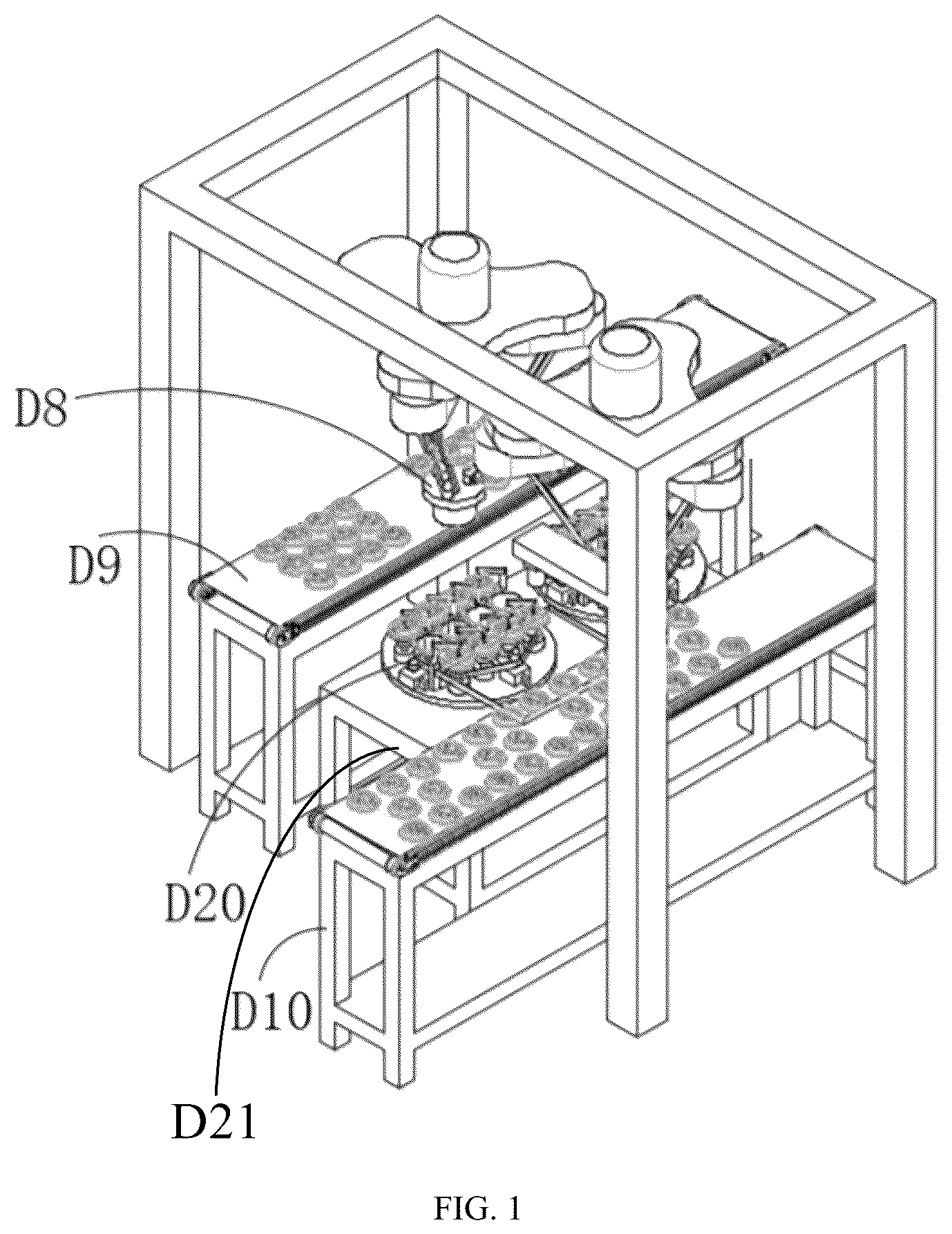
Specifically, the rolling device D includes a loading unit D 10 , a rolling unit D 20 , and a take-and-place unit D 8 . The loading unit D 10 is used to load and convey the unrolled pulp molded products. The loading unit D 10 includes a conveyor belt.
Preferably, the rolling unit D 20 in this embodiment has two and two rolling units D 20 are linearly distributed front and back at intervals. The two rolling unit D 20 are rotationally connected to a platform frame D 21 . Specifically, the rolling unit D 20 includes a horizontal rotating table D 1 , which is rotationally connected to the platform frame D 21 , and the platform frame D 21 is provided with a rotating table driving motor D 11 that drives the rotation of the horizontal rotating table 1 .
The upper surface of the horizontal rotating table D 1 is horizontally connected with at least one translatable rolling wheel D 2 . The translatable rolling wheel D 2 is connected with the translation driving mechanism D 3 and the translatable rolling wheel D 2 is connected with the rotation driving mechanism D 4 . The upper surface of the horizontal rotating table D 1 is rotationally connected with two rolling moving dies D 5 located on the periphery of each translatable rolling wheel D 2 . The unprocessed pulp molded product is sleeved on the rolling moving die D 5 , and a lower edge of the rolling moving die D 5 is provided with an annular groove which is in clearance fit with an outer edge of the translatable rolling wheel D 2 . The translatable rolling wheel D 2 is in contact with the outer wall of the pulp molded product to force the wall thickness of the pulp molded product to roll and deform into the inside of the annular groove. That is, an inner convex buckle with the same thickness as the wall thickness of the pulp molded product is made in the direction of the wall thickness of the pulp molded product, and the rotary pressing-down assembly D 6 is used to press down the unrolled pulp molded product placed on the rolling moving die D 5 . The rotary pressing-down assembly D 6 can be rotated facing away from the top of the rolling moving die D 5 when placing the unrolled pulp molded product to avoid collision and improve the efficiency of loading and unloading. The rolling moving die D 5 is connected with the rotary driving mechanism D 7 .
The rotation direction of the rolling moving die D 5 is opposite to the rotation direction of the translatable rolling wheel D 2 , and the rotation speeds of the rolling moving die D 5 and the translatable rolling wheel D 2 are the same.
Preferably, there are two rolling moving dies D 5 located at the periphery of each translatable rolling wheel D 2 and symmetrically distributed with the translatable rolling wheel D 2 as the center in this embodiment, each rolling moving die D 5 corresponds to the rotary pressing-down assembly D 6 , each rolling moving die D 5 corresponds to a rotary driving mechanism D 7 , and the rotary driving mechanism D 7 drives the rolling moving die D 5 to rotate. Two rolling moving dies D 5 can form alternate rolling and the finished pulp molded products can be taken out during the rolling, which greatly shorten the production cycle and greatly improve the production and processing efficiency. The translatable rolling wheel D 2 is close to one rolling moving die D 5 , so as to carry out the radial inward rolling of the unrolled pulp molded products, and the next unrolled pulp molded product is placed on another rolling moving die D 5 .
Preferably, the translatable rolling wheel D 2 in this embodiment has several and forms a row, and the rotation driving mechanism D 4 drives the translatable rolling wheels 2 to rotate synchronously. That is, one rotation driving mechanism D 4 drives all translatable rolling wheels D 2 to rotate synchronously. There are two rolling moving dies D 5 symmetrically distributed with the translatable rolling wheel D 2 as the center and disposed the periphery of each translatable rolling wheel D 2 , and the rolling moving dies D 5 are distributed in two rows. The expansion of the number can be applied to mass rolling production and processing. There are two rotary driving mechanisms D 7 and one rotary driving mechanism D 7 drives the rolling moving dies 5 on the same row to rotate synchronously. That is, when the unprocessed pulp molded products on one row of rolling moving dies D 5 are being rolled, the other row of rolling moving dies D 5 are placed on the unprocessed pulp molded products, and the waiting time is shortened by alternating, which can greatly improve the production and processing efficiency. The rotary pressing-down assemblies D 6 are distributed in two rows, and the rotary pressing-down assemblies D 6 on the same row act synchronously, which can be arranged conveniently and compact overall structure.
Preferably, the rotary pressing-down assembly D 6 includes a rotating cylinder D 60 and a pressing block D 61 connected to a rotating telescopic rod of the rotating cylinder 60 , and the pressing block D 61 is rotationally connected with the rotating telescopic rod of the rotating cylinder D 60 .
The pressing block D 61 and the rotating telescopic rod are rotationally connected through bearings or shaft sleeves, thus ensuring that the pulp molded products are pressed.
Furthermore, the translation driving mechanism D 3 includes a translation plate D 30 which is horizontally connected with the horizontal rotating table D 1 , two parallel guide rails are arranged on the horizontal rotating table D 1 , and two ends of the lower surface of the translation plate D 30 are respectively provided with sliding blocks which are connected with the guide rails respectively. The above structure can realize smooth sliding of the translation plate D 30 . The translatable rolling wheel D 2 is installed on the translation plate D 30 through a connecting shaft D 31 and the connecting shaft D 31 and the translation plate D 30 are rotationally connected. The connecting shaft D 31 and the translation plate D 30 can be rotationally connected through bearings or shaft sleeves. The horizontal rotating table D 1 is provided with a translation power assembly that drives the translation plate D 30 to move close to the rolling moving die D 5 and move facing away from the rolling moving die D 5 . The translation power assembly is one of the air cylinder, oil cylinder and servo motor cooperative screw insert.
The translation driving mechanism D 3 drives the translatable rolling wheel D 2 to move close to a row of rolling moving dies D 5 , and then the rolling processing is carried out. At this time, the rolled pulp molded products on the other row of rolling moving dies D 5 are unloaded, and the synchronous response improves the production and processing efficiency.
Furthermore, the rotation driving mechanism D 4 includes a linkage synchronous belt D 40 which is arranged around the two adjacent connecting shafts D 31 . Any one connecting shaft D 31 is connected with a driving motor D 42 through an active synchronous belt D 41 , that is, the power transmission is realized by the way of series connection. At the same time, the two adjacent active synchronous belts D 41 are staggered up and down, and the driving motor D 42 is fixed on the translation plate D 30 or the horizontal rotating table D 1 . The driving motor D 42 is a servo motor.
Furthermore, each rotary driving mechanism D 7 includes a rotating synchronous belt D 71 which is wound on the rolling rotating shafts D 70 connected with the rolling moving dies D 5 , and the rotating synchronous belt D 71 is connected with a rotating servo motor D 72 fixed on the horizontal rotating table D 1 . A section of the rotating synchronous belt D 71 wound on the rolling rotating shaft D 70 is wavy, which can ensure the tension of rotating synchronous belt D 71 and the timeliness of power output transmission.
Furthermore, the rotary pressing-down assemblies D 6 on one same row are staggered with the rotary pressing-down assemblies D 6 on the other same row. The staggered distribution can make reasonable use of space, avoid interference caused by two pairs of correspondence, and avoid the need for a larger width space.
Preferably, there are 2-8 translatable rolling wheels D 2 in this embodiment; 2-8 rolling moving dies D 5 are located in one row, and 2-8 rotary pressing-down assemblies D 6 are located in one row.
For example, there are four translatable rolling wheels D 2 in this embodiment; Four rolling moving dies D 5 are located in one row, and four rotary pressing-down assemblies D 6 are located in one row. During actual production, the corresponding quantity can be set according to the actual production quantity.
The translatable rolling wheels D 2 on the horizontal rotating table D 1 are arranged in one row, and the rolling moving dies D 5 are arranged in two rows. The translatable rolling wheels D 2 are close to one row of the rolling moving dies D 5 , while the rotary pressing-down assemblies D 6 press the unprocessed pulp molded products on the rolling moving dies D 5 before the translatable rolling wheels D 2 are close to the rolling moving dies D 5 . As the translatable rolling wheels D 2 are close to the rolling moving dies D 5 and the translatable rolling wheels D 2 and the rolling moving dies D 5 rotate in the opposite directions, at this time, the translatable rolling wheel D 2 rolls the pulp molded products on the rolling moving die D 5 in a circumferential way, and then the translatable rolling wheel D 2 resets. After the rolling, an annular convex buckle is formed on the inner wall of the pulp molded product, and an annular rolling groove corresponding to the annular convex buckle is formed on the outer wall of the pulp molded product.
At the same time of the above rolling, the rolling moving dies D 5 on the other row perform unloading, that is, the rotary pressing-down assemblies D 6 rotate and disengage from the rolling moving dies D 5 , and the unprocessed pulp molded products are placed on the rolling moving dies D 5 . When the rolling is completed, the horizontal rotating table D 1 will rotate 180°, at this time, the translatable rolling wheels D 2 are close to the unprocessed pulp molded products, and repeat the above actions to realize the repeated rolling processing.
As shown in , the take-and-place unit D 8 is used to place the unrolled pulp molded products conveyed by the loading unit D 10 on the rolling moving dies D 5 , and to obtain and transfer the rolled pulp molded products to the outside of the rolling unit D 20 . Preferably, there are two take-and-place units D 8 in this embodiment, one of which is located above the side of the loading unit D 10 and the other of which is located above the side of the unloading unit D 9 . One of the take-and-place units D 8 is used to place the unrolled pulp molded products conveyed by the loading unit D 10 on the two rolling units D 20 in a one by one way, the other take-and-place unit D 8 is used to take and transfer the pulp molded products that have been rolled by two rolling units D 20 to the unloading unit D 9 in a one by one way. The loading unit D 10 and the unloading unit D 9 are distributed in parallel and the rolling units D 20 are located between the loading unit D 10 and the unloading unit D 9 .
Furthermore, the take-and-place unit D 8 is installed on the gantry bracket D 80 , and a camera D 81 located at a loading end of the loading unit D 10 is installed on an inside of two ends of the gantry bracket D 80 . The camera D 81 is used to detect the position of the unprocessed pulp molded products on the loading unit D 10 and determine whether there is loading.
Specifically, the take-and-place unit D 8 is connected to the lower side of the top of the gantry bracket D 80 through a take-and-place translation driving device D 86 . The take-and-place translation driving device D 86 drives the take-and-place unit D 8 to translate, thus the rolled pulp molded products are transferred to the unloading unit D 9 . The take-and-place translation driving device D 86 is adopted by one of the synchronous belt translation drive mode, screw nut translation drive mode and guide slide translation drive mode.
Furthermore, the take-and-place unit D 8 includes a triangle block D 82 arranged horizontally. Each corner of the lower surface of the triangle block D 82 is respectively connected with an upper connecting block D 83 . The lower surface of each upper connecting block D 83 is connected with a connecting rod D 84 , and lower ends of the connecting rods D 84 converge inwards and connects to a lower connecting block D 85 . The lower surface of the lower connecting block D 85 is connected with a material taking device. The material taking device is an air-disk lifting reclaiming device, which belongs to the prior art, and its structure will not be further described in this embodiment.
A forming method of pulp molded products includes the following steps.
•
• S 1 , loading: unrolled pulp molded products are placed on the loading unit D 10 . • S 2 , placement: there are two take-and-place unit D 8 , one of the two take-and-place unit D 8 places the unrolled pulp molded products on the rolling moving dies D 5 of the rolling unit D 20 , and the rotary pressing-down assemblies D 6 rotate and press down to fix the unrolled pulp molded products on the rolling moving dies D 5 . • S 3 , rolling: the translatable rolling wheels D 2 of the rolling unit D 20 move close to the rolling moving dies D 5 in the step S 2 and perform radial inwards rolling of the unrolled pulp molded products. • S 4 , unloading: the horizontal rotating table D 1 of the rolling unit D 20 rotates 180°, and the other take-and-place unit D 8 takes the rolled pulp molded products and places them on the unloading unit D 9 . At this time, other rolling moving dies D 5 opposite to the rolling moving dies D 5 of the step S 2 repeat the above step S 2 .
Embodiment 2
The working principle and structure of this embodiment are basically the same as that of Embodiment 1. The different structure is that, as shown in , the rolling device includes a frame a 1 . Specifically, the frame a 1 of this embodiment includes a lower flat plate a 11 . The lower flat plate a 11 is connected with an upper flat plate a 13 through four stand columns a 12 . The lower flat plate a 11 and the upper flat plate a 13 are parallel.
The stand columns a 12 are distributed at four corners of the lower flat plate a 11 . Similarly, upper ends of the stand columns a 12 are connected to four corners of the upper flat plate a 13 . A space between the lower flat plate a 11 and the upper flat plate a 13 can form an installation space and play a protective role.
The frame a 1 is provided with a rotating table a 2 which is horizontally arranged, and the rotating table a 2 is connected with a rotating power device a 3 . Preferably, the rotating table a 2 of this embodiment is rotationally connected to the upper flat plate a 13 . The rotating table a 2 is provided with multiple rolling cavity dies a 4 which are rotatably connected with the rotating table a 2 and used to fix the pulp molded products. The rolling cavity dies a 4 are distributed in a circle. There are two rolling cavity dies a 4 in this embodiment. Of course, the number of rolling cavity dies a 4 can also be 3-6, which can be designed according to the actual production requirements.
The frame a 1 is provided with a support a 5 , which is fixed on the lower flat plate a 11 , and the frame a 1 is further provided with a lifting power member a 50 installed on the support a 5 , which is fixed on the lower flat plate a 11 , the lifting power member a 50 is an air cylinder or oil cylinder, and the lifting power member a 50 is connected with a pressing block a 51 which is connected with the lifting power member a 50 and the rotating power device a 3 drives the rotating table a 2 to rotate so that the rolling cavity dies a 4 alternately enter directly under the pressing block a 51 .
The scheme of using the rotating table to cooperate with multiple rolling cavity dies a 4 and make the multiple rolling cavity dies a 4 enter directly under the pressing block a 51 alternately can realize that one rolling station corresponds to multiple rolling cavity dies a 4 alternately, so as to shorten the waiting time between the unprocessed pulp molded products and the processed pulp molded products.
As shown in , a lifting seat a 6 located under the rotating table a 2 and a lifting power device a 60 used to drive the vertical lifting of the lifting seat a 6 are arranged on the frame a 1 , and a cavity die rotation power device a 3 a is arranged on the lifting seat a 6 . The lifting power device a 60 drives the cavity die rotation power device a 3 a to rise, and a clutch connection structure is connected between the cavity die rotation power device a 3 a and the rolling cavity die a 4 directly below the pressing block a 51 to realize the rotation of the rolling cavity die a 4 . The frame a 1 is further provided with a rolling terrace die a 7 which is relatively distributed with the rolling cavity die a 4 directly below the pressing block a 51 , the rolling terrace die a 7 is connected with a terrace die rotation driving device a 70 , and the terrace die rotation driving device a 70 is arranged on the translation driving device a 8 . The translation driving device a 8 is fixed on the lower flat plate a 11 . The terrace die rotation driving device a 70 and translation driving device a 8 are installed on the lower flat plate a 11 .
The clutch connection structure can realize the independent rotation control of the alternately entered rolling cavity dies a 4 to ensure the smoothness of the alternation, and further reduce the total number of rotating power and the input cost required for device manufacturing.
As shown in , the frame a 1 is provided with at least one sensor fixing block a 10 located outside the rotating power device a 3 , and a transversal surface of the sensor fixing block a 10 is U-shaped. There are two sensor fixing blocks a 10 in this embodiment, and the two sensor fixing blocks a 10 are symmetrically distributed. The rotating power device a 3 is located between the two sensor fixing blocks a 10 to facilitate position detection. The frame a 1 is provided with a position sensor a 11 fixed on one of the sensor fixing blocks a 10 . The position sensor a 11 is a photoelectric sensor. The rotating positioning blocks a 30 which the number is equal to the total number of rolling cavity dies a 4 are connected to the outside of the rotating power device a 3 , the rotating power device a 3 drives the rotating positioning blocks a 30 to rotate synchronously. When the position sensor a 11 is opposite to any one rotating positioning block a 30 , it means that one of the rolling cavity dies a 4 is directly below the pressing block a 51 . That is, when the position sensor a 11 detects the signal of the rotating positioning block a 30 , it means that the rolling cavity die a 4 rotates in place, and then the rolling operation can be carried out, ensuring the reliability of production and processing.
In an optimization scheme, the lifting seat a 6 is a rectangular frame, the cavity die rotation power device a 3 a is a servo motor and the servo motor is located in the rectangular frame to form the protection of the servo motor, the upper end of the servo motor is fixed on the top side of the rectangular frame and the output shaft of the servo motor is upward through the top side of the rectangular frame, and a Y-shaped sensor a 61 is arranged on the top surface of the rectangular frame, and the Y-shaped sensor a 61 is a photoelectric position sensor, a linkage plate a 31 is sleeved on the output shaft of the servo motor, and a notch a 32 is provided on the linkage plate a 31 . When the Y-shaped sensor a 61 enters the notch a 32 of the linkage plate a 31 , the output shaft of the servo motor rotates in place. The above structure is mainly to ensure the matching accuracy of the clutch connection structure, so as to prevent the position deviation caused by the dislocation from realizing the clutch connection.
In an optimization scheme, the clutch connection structure includes a flat connector a 33 arranged on the top of the output shaft of the servo motor, a clutch plate a 40 is connected at the lower end of each rolling cavity die a 4 , and a flat hole a 41 is arranged in a center of the clutch plate a 40 for inserting the flat connector a 33 . The top of the flat connector a 33 is provided with two conical surfaces, which form an inverted V-shaped surface to play a guiding role.
Furthermore, as shown in , the rotating power device a 3 includes a rotating cylinder, a rotating shaft a 34 is connected to the rotating power device a 3 , a rotating shaft base a 35 sleeved on the upper end of the rotating shaft a 34 is disposed on the frame a 1 , the rotating table a 2 is installed on the end surface of the rotating shaft a 34 extended to the upper end of the rotating shaft base a 35 , a cantilever block a 36 is disposed on a side of the rotating shaft base a 35 , and a support notch a 37 is provided on the cantilever block a 36 , and the output shaft of the servo motor is snapped in the support notch a 37 . The support notch a 37 plays a supporting and guiding role.
Furthermore, the rotating table a 2 includes a strip-shaped plate a 20 , a middle position of the strip-shaped plate a 20 is fixed on an upper end face of the rotating shaft a 34 , and two ends of the upper surface of the strip-shaped plate a 20 are respectively provided with the above-mentioned rolling cavity dies a 4 . Specifically, the two ends of the strip-shaped plate a 20 are respectively provided with mounting holes, and the above-mentioned rolling cavity dies a 4 are rotatably installed in the mounting holes respectively. The clutch plate a 40 is located in the mounting hole, the two ends of the lower surface of the strip-shaped plate a 20 are respectively provided with a lower plate a 21 located under the clutch plate a 40 , a center of the rotating shaft base a 35 is provided with a shaft through hole, the upper end of the rotating shaft a 34 is connected with a bearing group a 38 and the bearing group a 38 is installed in the shaft through hole, the middle position of the strip-shaped plate a 20 is fixed at the upper end of the bearing group a 38 , and the two lower plates a 21 are symmetrically arranged with the axis of the bearing group a 38 , and opposite inner edges of the two lower plates a 21 are respectively provided with arc concave surfaces a 22 matching with the outer wall of the bearing group a 38 . The arc concave surface a 22 can improve the smoothness of rotation and can further improve the matching strength of the connection.
The bearing group a 38 includes an upper fixing ring, a lower fixing ring, and a bearing piece installed between the upper fixing ring and the lower fixing ring. The arc concave surface a 22 matches a circumferential direction of the lower fixing ring.
Furthermore, the upper surface of the strip-shaped plate a 20 is provided with a disc plate a 24 , and an outer edge of the disc plate a 24 is provided with circular opening grooves a 25 for the rolling cavity dies a 4 to extend. The disc plate a 24 can form a guard.
In an optimization scheme, the translation driving device a 8 includes a fixed groove a 80 provided on the lower flat plate, two ends of the fixed groove a 80 are closed, an upper side of the fixed groove a 80 is provided with an opening and a guide rail a 81 parallel to the fixed groove a 80 , the fixed groove a 80 is connected with a servo motor a 82 , and a U-shaped sliding plate a 83 closes the upper notch of the fixed groove a 80 and forms an inverted U-shape, the servo motor a 82 is connected with the U-shaped sliding plate a 83 through a driving structure disposed in the fixed groove a 80 to drive the U-shaped sliding plate a 83 to move along the length direction of the fixed groove a 80 . Furthermore, the driving structure includes a drive screw rod connected to the output shaft of the servo motor a 82 , two ends of the drive screw rod are installed on the fixed groove a 80 through bearings, and the drive screw rod is sleeved with a screw sleeve, the screw sleeve is installed on the lower surface of the U-shaped sliding plate a 83 through the fixed seat. The matching of drive screw rod and screw sleeve can improve the control accuracy, and cooperate with the servo motor to accurately control the travel of the rolling terrace die a 7 .
The translation driving device a 8 further includes a transverse translation plate a 84 , an end of which is fixed on the U-shaped sliding plate a 83 , the other end of which is connected with a sliding block a 85 and the sliding block a 85 is connected with the guide rail a 81 in a sliding way, and the terrace die rotation driving device a 70 is fixed on the transverse translation plate a 84 . The above structure can further improve the compactness of the layout.
Furthermore, the upper flat plate a 13 is provided with an avoidance hole 130 , the terrace die rotation driving device a 70 is a servo motor and the servo motor part extends into the avoidance hole 130 . This structure can further improve the compactness of the layout.
A forming method of pulp molded product includes the following steps.
•
• S 1 , an unrolled pulp molded product is fixed on the rolling cavity die a 4 ; the unrolled pulp molded product can be fixed on the rolling cavity die a 4 by using a manipulator or manually. • S 2 , the rotating table rotates and drives the rolling cavity die a 4 to enter directly under the pressing block a 51 ; the rolling cavity die a 4 corresponds to the rotating positioning block a 30 , that is, the position sensor a 11 detects the signal of the rotating positioning block a 30 opposite to the rolling cavity die a 4 directly below the pressing block a 51 . • S 3 , the lifting power member a 50 drives the pressing block a 51 to lower and press the top of the pulp molded product. • S 4 , the lifting power device a 60 drives the cavity die rotation power device a 3 a to rise, the cavity die rotation power device a 3 a and the rolling cavity die a 4 are connected through the clutch connection structure, and the translation driving device a 8 drives the rolling terrace die a 7 installed on the terrace die rotation driving device a 70 to move close to the rolling cavity die a 4 directly below the pressing block a 51 ; • that is, the Y-shaped sensor a 61 enters into the notch a 32 , indicating that the position is in place. • S 5 , the cavity die rotation power device a 3 a drives the rolling cavity die a 4 to rotate, the terrace die rotation driving device a 70 drives the rolling terrace die a 7 to rotate at the same time, and the rotation direction of the rolling cavity die a 4 is opposite to the rotation direction of the rolling terrace die a 7 , and the translation driving device a 8 drives the rolling terrace die a 7 to be in contact with the outer wall of the pulp molded product and roll the pulp molded product. • S 6 , the rolled pulp molded product is transferred to the lower part of the pressing block by using the rotating table, and then the next unprocessed pulp molded product on the rotating table enter the lower part of the pressing block, the above steps S 3 -S 5 are repeated, and at the same time, the rolled pulp molded product is unloaded, that is, the pulp molded product is prepared.
The air cylinder or oil cylinder in this embodiment is a double-rod air cylinder or a double-rod air oil cylinder.
As another embodiment, the working principle and structure of this embodiment are basically the same as that of Embodiment 1, but the different structure is that there are 3-6 rolling units D 20 .
As another embodiment, there is one rolling unit D 20 and one take-and-place unit D 8 , and the unloading action is performed after the loading action.
As another embodiment, the structures of the edge cutting device C and the rolling device are basically the same as that of Embodiment 1, the edge cutting can be realized only by replacing the following: the translatable rolling wheel D 2 is replaced with a translatable rotary cutter with circular shape, and the rolling moving die D 5 is replaced with the rotary cutting moving die to improve the rotary cutting processing efficiency. The structure of the rotary cutting moving die is similar to that of the rolling moving die D 5 , the difference is that an avoidance groove on the rotary cutting moving die is in a more downward position, and when the translatable rotary cutter performs edge cutting, it enters the avoidance groove.
The specific embodiments described herein are only illustrative of the spirit of the disclosure. Those skilled in the related art can make various modifications or supplements to the specific embodiments described or use similar methods to replace them, but they will not deviate from the spirit of the disclosure or go beyond the scope defined in the appended claims.
Figures (9)
Citations
This patent cites (6)
- US4721500
- US2009/0032206
- US2015/0292154
- US2020/0384671
- US211256499
- USWO-2015042874