Collapsible Stand Assembly for Drying and Storage
Abstract
A collapsible stand assembly for drying and storage includes an upper assembly and a lower assembly. The upper assembly is configured to be stacked above the lower assembly. A plurality of first arms extend outward from an upper frame of the upper assembly, and a plurality of second arms extend outward from a lower frame of the lower assembly. A plurality of legs extend outward from the lower frame of the lower assembly. The first and second arms and the legs are collapsible into a compact configuration.
Claims (18)
1. A collapsible stand assembly for drying and storage, comprising: an upper assembly and a lower assembly, the upper assembly stacked above the lower assembly; a plurality of first arms extending outward from an upper frame of the upper assembly; a plurality of second arms extending outward from a lower frame of the lower assembly; a plurality of legs extending outward from the lower frame of the lower assembly, wherein the first and second arms and the legs are collapsible into a compact configuration, wherein the second arms and the legs are pivotally coupled to each other.
9. A collapsible stand assembly for drying and storage, comprising: an upper assembly and a lower assembly, the upper assembly stacked above the lower assembly; a plurality of first arms extending outward from an upper frame of the upper assembly; a plurality of second arms extending outward from a lower frame of the lower assembly; a plurality of legs extending outward from the lower frame of the lower assembly, a first hub hingedly coupling a plurality of support members to the upper frame, the first hub in a sliding arrangement relative to the upper frame; a second hub hingedly coupling the first arms to the upper frame; a third hub hingedly coupling the legs to the lower frame, the third hub in a sliding arrangement relative to the lower frame; and a fourth hub hingedly coupling the second arms to the lower frame, wherein the second arms and the legs are pivotally coupled to each other.
15. A collapsible stand assembly for drying and storage, comprising: an upper assembly and a lower assembly, the upper assembly stacked above the lower assembly; a plurality of first arms extending outward from an upper frame of the upper assembly; a plurality of second arms extending outward from a lower frame of the lower assembly; a plurality of legs extending outward from the lower frame of the lower assembly, a first hub hingedly coupling a plurality of support members to the upper frame, the first hub in a sliding arrangement relative to the upper frame; a second hub hingedly coupling the first arms to the upper frame, a third hub hingedly coupling the legs to the lower frame, the third hub in a sliding arrangement relative to the lower frame; and a fourth hub hingedly coupling the second arms to the lower frame, wherein the second arms and the legs are pivotally coupled to each other, and the first arms and the support members are pivotally coupled to each other.
Show 15 dependent claims
2. The collapsible stand assembly of claim 1 , wherein the upper assembly further comprises: a first hub hingedly coupling a plurality of support members to the upper frame, the first hub in a sliding arrangement relative to the upper frame; a second hub hingedly coupling the first arms to the upper frame, wherein the first hub selectively translates along the length of the upper frame to collapse or extend the first arms, and the second hub is securely coupled to a first end of the upper frame and is not configured to translate relative to the upper frame.
3. The collapsible stand assembly of claim 2 , wherein the first arms and the support members are pivotally coupled to each other.
4. The collapsible stand assembly of claim 1 , wherein the lower assembly further comprises: a third hub hingedly coupling the legs to the lower frame, the third hub in a sliding arrangement relative to the lower frame; a fourth hub hingedly coupling the second arms to the lower frame, wherein the third hub selectively translates along the length of the lower frame to collapse or extend the legs, and the fourth hub is securely coupled to a first end of the lower frame and is not configured to translate relative to the lower frame.
5. The collapsible stand assembly of claim 1 , wherein collapsing or extending the legs causes in the corresponding folding or extension of the second arms.
6. The collapsible stand assembly of claim 1 , wherein the first and second arms and the legs are nested together in a stacked configuration.
7. The collapsible stand assembly of claim 1 , further comprising a connector pipe inserted into and affixed to an internal lower portion of the upper frame, wherein the connector pipe is configured to translate within an upper portion of the lower frame.
8. The collapsible stand assembly of claim 7 , wherein the connector pipe is configured to be inserted inside the lower frame to stack the upper assembly over the lower assembly.
10. The collapsible stand assembly of claim 9 , wherein the first hub selectively translates along the length of the upper frame to collapse or extend the first arms, and the second hub is securely coupled to a first end of the upper frame and is not configured to translate relative to the upper frame.
11. The collapsible stand assembly of claim 9 , wherein the third hub selectively translates along the length of the lower frame to collapse or extend the legs, and the fourth hub is securely coupled to a first end of the lower frame and is not configured to translate relative to the lower frame.
12. The collapsible stand assembly of claim 9 , wherein the first arms and the support members are pivotally coupled to each other.
13. The collapsible stand assembly of claim 9 , further comprising a connector pipe inserted into and affixed to an internal lower portion of the upper frame, wherein the connector pipe is configured to translate within an upper portion of the lower frame.
14. The collapsible stand assembly of claim 9 , wherein the connector pipe is configured to be inserted inside the lower frame to stack the upper assembly over the lower assembly.
16. The collapsible stand assembly of claim 15 , wherein the first hub selectively translates along the length of the upper frame to collapse or extend the first arms, and the second hub is securely coupled to a first end of the upper frame and is not configured to translate relative to the lower frame.
17. The collapsible stand assembly of claim 15 , wherein the third hub selectively translates along the length of the lower frame to collapse or extend the legs, and the fourth hub is securely coupled to a first end of the lower frame and is not configured to translate relative to the lower frame.
18. The collapsible stand assembly of claim 15 , further comprising a connector pipe inserted into and affixed to an internal lower portion of the upper frame, wherein the connector pipe is configured to translate within an upper portion of the lower frame.
Full Description
Show full text →
CROSS REFERENCE TO RELATED APPLICATIONS
This application claims priority from U.S. provisional application No. 63/516,051, filed Jul. 27, 2023, entitled “EQUIPMENT STAND ASSEMBLY”, assigned to the present assignee and incorporated herein by reference.
FIELD OF THE INVENTION
The present invention relates to generally to equipment for storage and drying of clothes and accessories, and more particularly to a collapsible stand assembly for supporting clothes and accessories for drying and storage.
RELATED ART
In various sports disciplines such as hockey, football, and skiing, athletes utilize a diverse range of clothing and accessories for performance and protection. These garments and accessories frequently become wet due to external factors like rain or perspiration. Proper maintenance of these items is crucial, as storing them without adequate drying can lead to the growth of mold, mildew, and unpleasant odors, compromising their usability and longevity.
Existing solutions in the form of stands or racks are often ill-suited for the unique requirements of drying sports clothing and accessories. Their design limitations make them less effective in facilitating proper airflow and drying, which is vital for moisture removal and preventing mold and mildew.
Furthermore, these traditional stands and racks are typically tailored for specific types of clothing and accessories, lacking versatility in accommodating various sports gear. Their fixed construction often obstructs pathways when placed in a space, limiting flexibility in placement and usage. Additionally, their bulky and cumbersome nature makes them impractical for transportation, creating challenges for athletes who need to transport them over distances. This limitation restricts their mobility and convenience, particularly during competitions or training sessions away from home.
Accordingly, there exists a need for an improved solution that addresses the specific challenges associated with drying and storing sports clothing and accessories effectively, while also offering enhanced adaptability, space efficiency, and portability.
SUMMARY OF THE INVENTION
Illustrative embodiments provide a collapsible stand assembly for drying and storage of clothes, accessories and equipment. In one embodiment, a collapsible stand assembly includes an upper assembly and a lower assembly. The upper assembly is configured to be stacked above the lower assembly. A plurality of first arms extend outward from an upper frame of the upper assembly, and a plurality of second arms extend outward from a lower frame of the lower assembly. A plurality of legs extend outward from the lower frame of the lower assembly. The first and second arms and the legs are nested together in a stacked configuration. The first and second arms and the legs are collapsible into a compact configuration.
In an illustrative embodiment, the upper assembly includes a first hub which hingedly couples a plurality of support members to the upper frame. The first hub is in a sliding arrangement relative to the upper frame. The upper assembly includes a second hub which hingedly couples the first arms to the upper frame. The first hub selectively translates along the length of the upper frame to collapse or extend the first arms, and the second hub is securely coupled to a first end of the upper frame and is not configured to translate relative to the upper frame.
In an illustrative embodiment, the lower assembly includes a third hub which hingedly couples the legs to the lower frame. The third hub is in a sliding arrangement relative to the lower frame. The lower assembly includes a fourth hub which hingedly couples the second arms to the lower frame. The third hub selectively translates along the length of the lower frame to collapse or extend the legs, and the fourth hub is securely coupled to a first end of the lower frame and is not configured to translate relative to the lower frame.
In an illustrative embodiment, the first arms and the support members are pivotally coupled to each other, and the second arms and the legs are pivotally coupled to each other.
In an illustrative embodiment, a connector pipe is inserted into and affixed to an internal lower portion of the upper frame. The connector pipe is configured to translate within an upper portion of the lower frame. The connector pipe is configured to be inserted inside the lower frame to stack the upper assembly over the lower assembly.
In an illustrative embodiment, a collapsible stand assembly for drying and storage of clothes, accessories and equipment includes an upper assembly and a lower assembly. The upper assembly is stacked above the lower assembly. A plurality of first arms extend outward from an upper frame of the upper assembly, and a plurality of second arms extend outward from a lower frame of the lower assembly. A plurality of legs extend outward from the lower frame of the lower assembly. A first hub hingedly couples a plurality of support members to the upper frame. The first hub is in a sliding arrangement relative to the upper frame. A second hub hingedly couples the first arms to the upper frame. A third hub hingedly couples the legs to the lower frame. The third hub is in a sliding arrangement relative to the lower frame. A fourth hub hingedly coupling the second arms to the lower frame.
BRIEF DESCRIPTION OF THE DRAWINGS
depicts a collapsible stand assembly in accordance with an illustrative embodiment;
depicts a lower assembly in accordance with an illustrative embodiment;
depicts an upper assembly in accordance with an illustrative embodiment;
depict upper and lower perspective view of hubs in accordance with an illustrative embodiment;
illustrates a partially exploded view of the stand assembly; and
illustrates the stand assembly configured in its collapsed state.
DESCRIPTION OF EXEMPLARY EMBODIMENTS
Illustrative embodiments are described below. It should be understood that various components, parts, and features of the different embodiments may be combined together and/or interchanged with one another, all of which are within the scope of the present application, even though not all variations and particular embodiments are shown in the drawings.
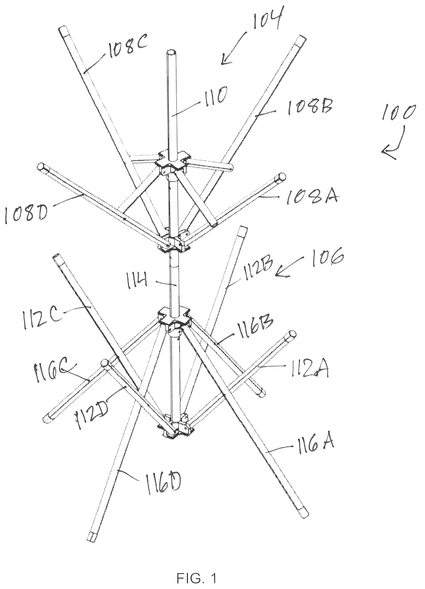
depicts collapsible stand assembly 100 in accordance with an illustrative embodiment. Stand assembly 100 is configured for drying and storage of clothes, accessories and equipment. Stand assembly 100 provides a framework with upper and lower frames. A plurality of arms extend outward from the upper and lower frames. The arms are adaptable for holding various items such as sporting equipment, accessories, towels, and uniforms. The arms may be at different elevations or levels. The arms are nestled together in a stacked configuration. When not in use, the arms can be collapsed or folded into a compact configuration for storage.
In one embodiment, stand assembly 100 is a tree-like structure, where the multiple levels or tiers of arms extend outward from the upper and lower frames. The tree-like structure with multiple levels or tiers or arms enables stand assembly 100 to hold and support clothes, accessories and equipment for drying and storage. The arms are nestled together in a stacked configuration. Because the arms can be collapsed or folded into a compact package, the tree-like structure can be conveniently stored or transported.
In an illustrative embodiment, stand assembly 100 includes upper assembly 104 and lower assembly 106 . Upper assembly 104 can be stacked above lower assembly 108 . Upper assembly 104 includes a plurality of arms 108 A- 108 D extending outward from upper frame 110 . Although, upper assembly 104 is depicted as having four arms, upper assembly 104 can be configured to include more or fewer number of arms.
In some embodiments, arms 108 A- 108 D extend outward, angling upward from upper frame 110 . Upper frame 110 supports arms 108 A- 108 D and provides stability to arms 108 A- 108 D. Arms 108 A- 108 D are configured to hold various items such as sporting equipment, accessories, towels and uniforms. Arms 108 A- 108 D can be selectively collapsed or folded to reduce the spatial footprint and become less obstructive. Upper frame 110 supports the operation of arms 108 A- 108 D.
Lower assembly 106 includes a plurality of arms 112 A- 112 D extending outward from lower frame 114 . In some embodiments, arms 112 A- 112 D extend outward, angling upward from lower frame 110 . Lower frame 114 supports arms 112 A- 112 D and provides stability to arms 112 A- 112 D. Arms 112 A- 112 D can be selectively collapsed or folded to reduce the spatial footprint and become less obstructive.
Lower assembly 106 includes a plurality of legs 116 A- 116 extending outward from lower frame 114 . Legs 116 A- 116 D serve to support stand assembly 100 when it is placed on the ground. Angling downward from lower frame 114 , legs 116 A- 116 D provide stability to stand assembly 100 , ensuring it remains vertically oriented. Although, lower assembly 106 is depicted as having four arms and four legs, lower assembly 106 can be configured to include more or fewer number of arms and legs. When upper assembly 104 is stacked above lower assembly 106 , multiple levels or tiers of arms are provided to hold sporting equipment, accessories, towels, uniforms, or any other items for drying or storage.
depicts lower assembly 106 in accordance with an illustrative embodiment. Lower assembly 106 includes lower frame 114 , opposing hubs 204 A and 205 B, arms 112 A- 112 D and legs 116 A- 116 D.
Hub 204 A is hingedly coupled to legs 116 A- 116 D. Hub 204 A is in a sliding arrangement relative to lower frame 114 . Hub 204 A selectively translates along the length of lower frame 114 so as to collapse arms 112 A- 112 D and legs 116 A- 116 D inward or alternatively extend arms 112 A- 112 D and legs 116 A- 116 D outwardly. In , lower assembly 106 is shown in an extended orientation with arms 112 A- 112 D and legs 116 A- 116 D extended outwardly. Hub 204 B hingedly couples arms 112 A- 112 D to lower frame 114 .
Arms 112 A and legs 116 A are also pivotally coupled to one another. In the illustrative embodiment, arm 112 A is pivotally coupled to leg 116 A, arm 112 B is pivotally coupled to leg 116 B, arm 112 C is pivotally coupled to leg 116 C, and arm 112 D is pivotally coupled to leg 116 D. As a result, if legs 116 A- 116 D are collapsed or folded, arms 112 A- 112 D also fold or collapse, and if legs 116 A- 116 D are extended outward, arms 112 A- 112 D also extend outward.
Hub 204 B is securely coupled to a first end of lower frame 114 . Hub 204 B is not configured to translate relative to lower frame 114 , and hub 204 B is not in a sliding arrangement with lower frame 114 .
depicts upper assembly 104 in accordance with an illustrative embodiment. Upper assembly 104 includes upper frame 110 , opposing hubs 206 A and 206 B, arms 108 A- 108 D and support members 118 A- 118 D. Upper assembly 104 is similar in form and function to that of lower assembly 106 . Hub 206 B is affixed to upper frame 110 . Hub 206 A is configured to translate along upper frame 110 . Thus, hub 206 A is in a sliding arrangement relative to upper frame 110 . Support members 118 A- 118 D are hingedly coupled to hub 206 A. Support members 118 A- 118 D are also coupled to respective arms 108 A- 108 D. Upper assembly 104 is configured to be stacked above lower assembly 106 .
In an example embodiment, upper frame 110 and lower frame 114 are made using hollow pipes. Upper frame 110 includes connector pipe 220 inserted into and affixed to an internal lower portion of upper frame 110 . Connector pipe 220 sticks out from the bottom of upper frame 110 and is configured to translate within an upper portion of lower frame 114 . Connector pipe 220 is inserted inside lower frame 114 to stack upper assembly 104 over lower assembly 106 .
depict upper and lower perspective view of the hubs in accordance with an illustrative embodiment. The embodiment depicted is representative of hubs 204 A- 204 D and 206 A- 206 D. A plurality of notches in the hub bodies are made for the legs and arms to be attached thereto. A plurality of apertures are selectively positioned to permit hinged movement of the legs and arms. One or more apertures are included within a central main aperture to selectively permit affixing the hub to one of the central bodies.
illustrates an enlarged view, partially exploded, of the stand assembly 100 . Within this illustration, pipe 220 is depicted extending beneath upper frame 110 , positioned for insertion into lower frame 114 . Tether 610 is integrated internally within sections of both the upper frame 110 and lower frame 114 . Tether 610 is designed with elastic properties, facilitating the maintenance of a compressive load between upper assembly 104 and lower assembly 106 . This elastic tension serves to resist any tendency towards separation between the upper and lower assemblies.
illustrates stand assembly 100 configured in its collapsed state. Here, the legs and arms of both the upper and lower assemblies are folded adjacent to their respective frames. This collapse results in stand assembly 100 adopting a nested storage configuration, significantly reducing the amount of space required for storage purposes.
Variations to stand assembly 100 are possible and within the scope of the disclosure.
Figures (5)
Citations
This patent cites (30)
- US140193
- US146308
- US606401
- US617611
- US883162
- US1259623
- US1344660
- US1525701
- US1713673
- US1862644
- US1883435
- US2022712
- US2259390
- US2794556
- US3038690
- US3464664
- USD294758
- US4923156
- US4989123
- US5280841
- US5449075
- US5819961
- US5979676
- US7025215
- US7077276
- US7775382
- US8418860
- US9909250
- US2015/0083678
- US2023/0190013