Abstract
A creasing apparatus includes a top plate having an upper surface supporting a fabric, a robot manipulator, a folding assembly mounted on the robot manipulator and configured to make a crease on the fabric by pinching the fabric from above, and a control device configured to control the robot manipulator and the folding assembly.
Claims (6)
1. A creasing apparatus comprising: a top plate having an upper surface supporting a fabric; a robot manipulator; a folding assembly mounted on the robot manipulator and configured to make a crease on the fabric by pinching the fabric from above; a control device configured to control the robot manipulator and the folding assembly; and a camera mounted on the robot manipulator and configured to be able to photograph the fabric, wherein the control device is configured to control the robot manipulator based on image data of the fabric acquired by the camera to allow a target portion of the fabric on which the crease is to be made and the folding assembly to face each other.
Show 5 dependent claims
2. The creasing apparatus according to claim 1 , wherein, after the target portion of the fabric and the folding assembly face each other, the control device is configured to control the folding assembly to allow the folding assembly to pinch the target portion of the fabric.
3. The creasing apparatus according to claim 1 , further comprising a heating device configured to heat the top plate, wherein the folding assembly makes the crease on the fabric after the fabric is heated by the heating device with the top plate interposed therebetween.
4. The creasing apparatus according to claim 1 , wherein the folding assembly includes a first hand, and a second hand configured to pinch the fabric between the first hand and the second hand.
5. The creasing apparatus according to claim 4 , wherein the folding assembly further includes a mountain folding member disposed below the first hand, and a scraping member disposed below the second hand and movable to approach the mountain folding member or to be separated from the mountain folding member, and the first hand and the second hand pinch a portion of the fabric mountain-folded by the mountain folding member and the scraping member.
6. The creasing apparatus according to claim 5 , wherein the folding assembly includes a folding-back member configured to fold back an end portion of the fabric pinched between the first hand and the second hand, and releases pinching of the fabric between the first hand and the second hand after the end portion of the fabric is folded back.
Full Description
Show full text →
CROSS-REFERENCE TO RELATED APPLICATIONS
This application is based on and claims priority under 35 USC 119 from Japanese Patent Application No. 2022-186480 filed on Nov. 22, 2022.
TECHNICAL FIELD
The technology disclosed in the present specification relates to a creasing apparatus.
BACKGROUND ART
As disclosed in JP2022-072371A, when clothing is manufactured, a crease is made on a fabric.
SUMMARY OF INVENTION
In the related art, a crease is made on a fabric by a worker. To efficiently produce clothing, it is desired to automatically make the crease on the fabric.
An aspect of the present invention is a creasing apparatus that includes a top plate having an upper surface supporting a fabric, a robot manipulator, a folding assembly mounted on the robot manipulator and configured to make a crease on the fabric by pinching the fabric from above, and a control device configured to control the robot manipulator and the folding assembly.
According to the creasing apparatus, a crease is automatically made on a fabric.
BRIEF DESCRIPTION OF DRAWINGS
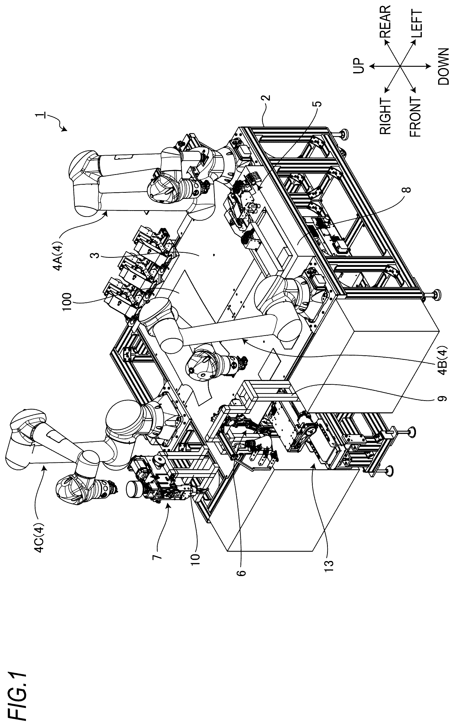
is a perspective view showing a sewing apparatus according to an embodiment;
is a plan view showing the sewing apparatus according to the embodiment;
is a perspective view showing a folding assembly mounted on a tip portion of a first robot manipulator according to the embodiment;
is a perspective view showing a feeding assembly mounted on a tip portion of a second robot manipulator according to the embodiment;
is a perspective view showing a sewing machine assembly mounted on a tip portion of a third robot manipulator according to the embodiment;
is a block diagram showing a control device of the sewing apparatus according to the embodiment;
is a perspective view showing the folding assembly according to the embodiment;
is a side view showing the folding assembly according to the embodiment;
is a diagram showing an operation of the folding assembly according to the embodiment;
is a diagram showing the operation of the folding assembly according to the embodiment;
is a diagram showing the operation of the folding assembly according to the embodiment;
is a diagram showing the operation of the folding assembly according to the embodiment;
is a diagram showing the operation of the folding assembly according to the embodiment;
is a diagram showing the operation of the folding assembly according to the embodiment;
is a diagram showing the operation of the folding assembly according to the embodiment;
is a diagram showing the operation of the folding assembly according to the embodiment;
is a diagram showing the operation of the folding assembly according to the embodiment;
is a diagram showing the operation of the folding assembly according to the embodiment; and
is a diagram showing the operation of the folding assembly according to the embodiment.
DESCRIPTION OF EMBODIMENTS
Hereinafter, an embodiment will be described with reference to the drawings. In the embodiment, a positional relationship of each part will be described using terms such as left, right, front, rear, upper, and lower. Such terms indicate a relative position or direction with respect to the center of a sewing apparatus 1 .
[Sewing Apparatus]
is a perspective view showing the sewing apparatus 1 according to the embodiment. is a plan view showing the sewing apparatus 1 according to the embodiment. As shown in , the sewing apparatus 1 includes a pedestal 2 , a top plate 3 , a robot manipulator 4 , a folding assembly 5 , a feeding assembly 6 , and a sewing machine assembly 7 .
The pedestal 2 supports each of the top plate 3 and the robot manipulator 4 . The top plate 3 has an upper surface that supports a fabric 100 . Abase end portion of the robot manipulator 4 is fixed to the pedestal 2 around the top plate 3 . Each of the folding assembly 5 , the feeding assembly 6 , and the sewing machine assembly 7 is attached to and detached from a tip portion of the robot manipulator 4 . Each of the folding assembly 5 , the feeding assembly 6 , and the sewing machine assembly 7 can perform a predetermined operation on the fabric 100 while being mounted on the tip portion of the robot manipulator 4 .
The robot manipulator 4 includes an articulated robot. In the embodiment, the robot manipulator 4 is a vertically articulated robot. Note that the robot manipulator 4 may be a horizontally articulated robot. The robot manipulator 4 includes a base member, a rotating member, a first arm, a second arm, a third arm, a rotating actuator, a first rotating actuator, a second rotating actuator, and a third rotating actuator. The base member is fixed to the pedestal 2 . The rotating member is rotatably supported by the base member. The rotating member is supported by the base member to be rotatable around a rotating shaft extending in the vertical direction. The first arm is rotatably connected to the rotating member. The first arm is rotatably connected to the rotating member around a first rotating shaft. The first rotating shaft is orthogonal to an axis parallel to the rotating shaft. The second arm is rotatably connected to a tip portion of the first arm. The second arm is rotatably connected to the first arm around a second rotating shaft. The second rotating shaft is parallel to the first rotating shaft. The third arm is rotatably connected to a tip portion of the second arm. The third arm is rotatably connected to the second arm around a third rotating shaft. The third rotating shaft is parallel to the second rotating shaft. Any one of the folding assembly 5 , the feeding assembly 6 , and the sewing machine assembly 7 is mounted on a tip portion of the third arm. The rotating actuator generates power to rotate the rotating member. The first rotating actuator generates power to rotate the first arm. The second rotating actuator generates power to rotate the second arm. The third rotating actuator generates power to rotate the third arm.
A plurality of robot manipulators 4 are provided. In the embodiment, three robot manipulators 4 are provided. The robot manipulator 4 includes a first robot manipulator 4 A, a second robot manipulator 4 B, and a third robot manipulator 4 C. The structure of the first robot manipulator 4 A, the structure of the second robot manipulator 4 B, and the structure of the third robot manipulator 4 C are substantially the same.
The folding assembly 5 can be attached to and detached from each of a tip portion of the first robot manipulator 4 A, a tip portion of the second robot manipulator 4 B, and a tip portion of the third robot manipulator 4 C. The feeding assembly 6 can be attached to and detached from each of the tip portion of the first robot manipulator 4 A, the tip portion of the second robot manipulator 4 B, and the tip portion of the third robot manipulator 4 C. The sewing machine assembly 7 can be attached to and detached from each of the tip portion of the first robot manipulator 4 A, the tip portion of the second robot manipulator 4 B, and the tip portion of the third robot manipulator 4 C.
The folding assembly 5 performs a folding operation of making a crease on the fabric 100 . The feeding assembly 6 performs a feeding operation of feeding the fabric 100 in a predetermined direction when a seam is made on the fabric 100 . The sewing machine assembly 7 performs a sewing operation of making the seam on the fabric 100 .
A support base 8 , a suspending member 9 , and a suspending member 10 are fixed to the pedestal 2 around the upper surface of the top plate 3 . The folding assembly 5 is supported by the support base 8 when the folding assembly 5 is not mounted on the robot manipulator 4 . The feeding assembly 6 is suspended from the suspending member 9 when the feeding assembly 6 is not mounted on the robot manipulator 4 . The sewing machine assembly 7 is suspended from the suspending member 10 when the sewing machine assembly 7 is not mounted on the robot manipulator 4 .
The top plate 3 includes a throat plate 11 . The throat plate 11 is fixed to the center of the top plate 3 . An opening 12 is provided in the throat plate 11 . A shuttle is disposed directly below the throat plate 11 . A bobbin case is housed in the shuttle. The bobbin case holds a bobbin around which a bobbin thread is wound. The shuttle supplies the bobbin thread. A shuttle guidance mechanism 13 is disposed below the top plate 3 . The shuttle is movable between a sewing position directly below the throat plate 11 and a replacement position in front of the pedestal 2 while being guided by the shuttle guidance mechanism 13 . The shuttle is movable between the sewing position and the replacement position while being guided by the shuttle guidance mechanism 13 by power generated by a shuttle moving actuator. For example, when the bobbin is replaced, the shuttle is moved to the replacement position.
[Folding Assembly]
is a perspective view showing the folding assembly 5 mounted on the tip portion of the first robot manipulator 4 A according to the embodiment. As shown in , the folding assembly 5 is mounted on the tip portion of the first robot manipulator 4 A. The folding assembly 5 has a joint part 5 A connected to the tip portion of the first robot manipulator 4 A. The folding assembly 5 is mounted on the tip portion of the first robot manipulator 4 A with the joint part 5 A interposed therebetween. Note that the folding assembly 5 may be mounted on the tip portion of the second robot manipulator 4 B or the tip portion of the third robot manipulator 4 C.
The folding assembly 5 makes a crease on the fabric 100 by pinching the fabric 100 from above. The folding assembly 5 includes a first hand 5 D and a second hand 5 E. Here, the fabric 100 is pinched between the first hand 5 D and the second hand 5 E.
A camera 14 is mounted on the tip portion of the first robot manipulator 4 A. The camera 14 is capable of photographing the fabric 100 . The camera 14 photographs the fabric 100 supported by the top plate 3 from above. The camera 14 includes a main body part 14 A, a first lens 14 L, and a second lens 14 R. The main body part 14 A includes an image sensor that receives light incident through the first lens 14 L and the second lens 14 R. The image sensor includes a couple charged device (CCD) image sensor or a complementary metal oxide semiconductor (CMOS) image sensor. The main body part 14 A is fixed to the tip portion of the first robot manipulator 4 A with a connecting member 15 interposed therebetween. Each of the first lens 14 L and the second lens 14 R is disposed at the lower portion of the main body part 14 A. The second lens 14 R is disposed next to the first lens 14 L. Since the camera 14 includes the first lens 14 L and the second lens 14 R, a photographing range of the camera 14 becomes large. Note that the camera 14 including the first lens 14 L and the second lens 14 R may be a stereo camera.
[Feeding Assembly]
is a perspective view showing the feeding assembly 6 mounted on the tip portion of the second robot manipulator 4 B according to the embodiment. As shown in , the feeding assembly 6 is mounted on the tip portion of the second robot manipulator 4 B. The feeding assembly 6 has a joint part 6 A connected to the tip portion of the second robot manipulator 4 B. The feeding assembly 6 is mounted on the tip portion of the second robot manipulator 4 B with the joint part 6 A interposed therebetween. Note that the feeding assembly 6 may be mounted on the tip portion of the first robot manipulator 4 A or the tip portion of the third robot manipulator 4 C.
The feeding assembly 6 includes a first presser 61 and a second presser 62 that press the fabric 100 from above, a first belt 6 L supported by the first presser 61 , and a second belt 6 R supported by the second presser 62 . Each of the first belt 6 L and the second belt 6 R is ring-shaped. Each of the first belt 6 L and the second belt 6 R is an endless belt. A part of the first belt 6 L is disposed between the first presser 61 and the fabric 100 . A part of the second belt 6 R is disposed between the second presser 62 and the fabric 100 . Each of the first belt 6 L and the second belt 6 R is rotated by a feeding motor (not shown). The first presser 61 presses the first belt 6 L against the fabric 100 . The second presser 62 presses the second belt 6 R against the fabric 100 . By rotating each of the first belt 6 L and second belt 6 R pressed against the fabric 100 , the fabric 100 is fed in a predetermined direction.
[Sewing Machine Assembly]
is a perspective view showing the sewing machine assembly 7 mounted on the tip portion of the third robot manipulator 4 C according to the embodiment. As shown in , the sewing machine assembly 7 is mounted on the tip portion of the third robot manipulator 4 C. The sewing machine assembly 7 has a joint part 7 A connected to the tip portion of the third robot manipulator 4 C. The sewing machine assembly 7 is mounted on the tip portion of the third robot manipulator 4 C with the joint part 7 A interposed therebetween. Note that the sewing machine assembly 7 may be mounted on the tip portion of the first robot manipulator 4 A or the tip portion of the second robot manipulator 4 B.
The sewing machine assembly 7 includes a sewing machine motor 7 C, a thread take-up lever 7 D, and a needle bar 7 E. The needle bar 7 E holds a sewing machine needle 7 F. The sewing machine motor 7 C generates power to enable the needle bar 7 E to reciprocate in the vertical direction. The thread take-up lever 7 D supplies a needle thread to the sewing machine needle 7 F. The power generated by the sewing machine motor 7 C is transmitted to each of the needle bar 7 E and the thread take-up lever 7 D via a power transmission mechanism. The needle bar 7 E, the thread take-up lever 7 D, and the shuttle are interlocked. As the power generated by the sewing machine motor 7 C is transmitted to the needle bar 7 E, the needle bar 7 E and the sewing machine needle 7 F held by the needle bar 7 E reciprocate in the vertical direction. The power generated by the sewing machine motor 7 C is transmitted to the thread take-up lever 7 D, so that the thread take-up lever 7 D reciprocates in the vertical direction in conjunction with the needle bar 7 E. The shuttle is rotated in conjunction with the needle bar 7 E and the thread take-up lever 7 D. The sewing machine needle 7 F can pass through the opening 12 of the throat plate 11 . The shuttle is disposed directly below the throat plate 11 . By supplying a bobbin thread, the shuttle cooperates with the sewing machine needle 7 F to form a seam on the fabric 100 . When the seam is formed on the fabric 100 , the sewing machine assembly 7 is disposed directly above the throat plate 11 to allow the sewing machine needle 7 F to pass through the opening 12 in the throat plate 11 . When the seam is formed on the fabric 100 , the third robot manipulator 4 C disposes the sewing machine assembly 7 directly above the throat plate 11 . When the seam is formed on the fabric 100 , the feeding assembly 6 is disposed near the sewing machine assembly 7 . When the seam is formed on the fabric 100 , the second robot manipulator 4 B disposes the feeding assembly 6 near the sewing machine assembly 7 . While the fabric 100 is fed in a predetermined direction by the feeding assembly 6 , the needle bar 7 E of the sewing machine assembly 7 reciprocates in the vertical direction. The sewing machine assembly 7 forms the seam on the fabric 100 in cooperation with the sewing machine needle 7 F held by the needle bar 7 E and the shuttle.
Note that, as described with reference to , the camera 14 is mounted on the tip portion of the first robot manipulator 4 A having the folding assembly 5 mounted thereon. The camera 14 may be mounted on the tip portion of the second robot manipulator 4 B having the feeding assembly 6 mounted thereon. The camera 14 may be mounted on the tip portion of the third robot manipulator 4 C having the sewing machine assembly 7 mounted thereon.
[Control Device]
is a block diagram showing a control device 16 of the sewing apparatus 1 according to the embodiment. The control device 16 controls the robot manipulator 4 , the folding assembly 5 mounted on the robot manipulator 4 , the feeding assembly 6 mounted on the robot manipulator 4 , and the sewing machine assembly 7 mounted on the robot manipulator 4 . The control device 16 includes a computer system. The control device 16 includes a processor such as a central processing unit (CPU), a memory such as a read only memory (ROM) or a random access memory (RAM), and an input/output interface including an input/output circuit capable of inputting/outputting signals and data.
The control device 16 includes an image data acquisition unit 16 A, an image processor 16 B, a robot controller 16 C, a folding assembly controller 16 D, a feeding assembly controller 16 E, and a sewing machine assembly controller 16 F.
The image data acquisition unit 16 A acquires image data of the fabric 100 photographed by the camera 14 . The image processor 16 B calculates the position of the fabric 100 based on the image data of the fabric 100 acquired by the image data acquisition unit 16 A. In the embodiment, the image processor 16 B calculates a target portion of the fabric 100 on which the crease is to be made based on the image data of the fabric 100 acquired by the camera 14 . The image processor 16 B may calculate the position of the target portion of the fabric 100 based on the image data of the end portion of the fabric 100 . When the fabric 100 is provided with an alignment mark, the image processor 16 B may calculate the position of the target portion of the fabric 100 based on the image data of the mark. When the fabric 100 is provided with a pattern (a shape), the image processor 16 B may calculate the position of the target portion of the fabric 100 based on the image data of the pattern.
The robot controller 16 C controls the robot manipulator 4 . When the crease is made on the fabric 100 , the robot controller 16 C controls the first robot manipulator 4 A to allow the target portion of the fabric 100 on which the crease is to be made calculated by the image processor 16 B and the folding assembly 5 to face each other.
When the folding assembly 5 is mounted on the tip portion of the robot manipulator 4 , the robot controller 16 C controls the robot manipulator 4 to allow the tip portion of the robot manipulator 4 to approach the folding assembly 5 supported by the support base 8 . The folding assembly 5 is mounted on the robot manipulator 4 by connecting the joint part 5 A of the folding assembly 5 supported by the support base 8 to the tip portion of the robot manipulator 4 . When the folding assembly 5 is detached from the tip portion of the robot manipulator 4 , the robot controller 16 C controls the robot manipulator 4 to allow the folding assembly 5 mounted on the tip portion of the robot manipulator 4 to approach the support base 8 . After the folding assembly 5 is supported by the support base 8 , the connection between the tip portion of the robot manipulator 4 and the joint part 5 A of the folding assembly 5 is released.
When the feeding assembly 6 is mounted on the tip portion of the robot manipulator 4 , the robot controller 16 C controls the robot manipulator 4 to allow the tip portion of the robot manipulator 4 to approach the feeding assembly 6 suspended from the suspending member 9 . The feeding assembly 6 is mounted on the robot manipulator 4 by connecting the joint part 6 A of the feeding assembly 6 suspended from the suspending member 9 to the tip portion of the robot manipulator 4 . When the feeding assembly 6 is detached from the tip portion of the robot manipulator 4 , the robot controller 16 C controls the robot manipulator 4 to allow the feeding assembly 6 mounted on the tip portion of the robot manipulator 4 to approach the suspending member 9 . After the feeding assembly 6 is suspended from the suspending member 9 , the connection between the tip portion of the robot manipulator 4 and the joint part 6 A of the feeding assembly 6 is released.
When the sewing machine assembly 7 is mounted on the tip portion of the robot manipulator 4 , the robot controller 16 C controls the robot manipulator 4 to allow the tip portion of the robot manipulator 4 to approach the sewing machine assembly 7 suspended from the suspending member 10 . The sewing machine assembly 7 is mounted on the robot manipulator 4 by connecting the joint part 7 A of the sewing machine assembly 7 suspended from the suspending member 10 to the tip portion of the robot manipulator 4 . When the sewing machine assembly 7 is detached from the tip portion of the robot manipulator 4 , the robot controller 16 C controls the robot manipulator 4 to allow the sewing machine assembly 7 mounted on the tip portion of the robot manipulator 4 to approach the suspending member 10 . After the sewing machine assembly 7 is suspended from the suspending member 10 , the connection between the tip portion of the robot manipulator 4 and the joint part 7 A of the sewing machine assembly 7 is released.
The folding assembly controller 16 D controls the folding assembly 5 . The folding assembly controller 16 D controls the folding assembly 5 to allow the folding assembly 5 to pinch the target portion of the fabric 100 after the target portion of the fabric 100 and the folding assembly 5 face each other.
The feeding assembly controller 16 E controls the feeding assembly 6 . The sewing machine assembly controller 16 F controls the sewing machine assembly 7 .
In the embodiment, the creasing apparatus configured to make a crease on the fabric 100 is configured by the top plate 3 supporting the fabric 100 , the first robot manipulator 4 A, the folding assembly 5 mounted on the first robot manipulator 4 A, and the control device 16 .
[Folding Assembly]
is a perspective view showing the folding assembly 5 according to the embodiment. is a side view showing the folding assembly 5 according to the embodiment. As shown in , the folding assembly 5 includes the joint part 5 A, a base member 5 B, a pressurizing cylinder 5 C, a first hand 5 D, a second hand 5 E, a mountain folding member 5 F, a fixing member 5 G, a connecting member 5 H, a fixing member 5 J, a hinge mechanism 5 K, a folding-back cylinder 5 L, a folding-back member 5 M, a scraping cylinder 5 N, a scraping member 5 P, and a pressing member 5 R.
The joint part 5 A is connected to the tip portion of the first robot manipulator 4 A. The base member 5 B supports the joint part 5 A.
The pressurizing cylinder 5 C is, for example, an air cylinder. A cylinder part of the pressurizing cylinder 5 C is fixed to the base member 5 B. A rod part of the pressurizing cylinder 5 C is fixed to the fixing member 5 G.
The first hand 5 D is fixed to a lower end portion of the base member 5 B. The first hand 5 D includes the pressing member 5 R. The second hand 5 E is disposed in front of the first hand 5 D. The second hand 5 E is disposed to face the pressing member 5 R of the first hand 5 D. The second hand 5 E is fixed to the fixing member 5 J.
A rear end portion of the mountain folding member 5 F is fixed to the rear surface of the first hand 5 D with a screw. Apart of the mountain folding member 5 F is disposed below the first hand 5 D. The mountain fold member 5 F is a thin metal plate. The mountain folding member 5 F can be elastically deformed. The mountain folding member 5 F may be formed in a comb-teeth shape. A front end portion of the mountain folding member 5 F is bent downwards.
The fixing member 5 G and the fixing member 5 J are connected to each other via the connecting member 5 H. The fixing member 5 G, the connecting member 5 H, and the fixing member 5 J are fixed. The fixing member 5 G, the connecting member 5 H, and the fixing member 5 J may be considered to be integrated with each other (a single member). A front end portion of the base member 5 B and the fixing member 5 J are connected to each other via the hinge mechanism 5 K. A rotation shaft of the hinge mechanism 5 K extends in the left-and-right direction.
When the pressurizing cylinder 5 C extends, the fixing member 5 G, the connecting member 5 H, and the fixing member 5 J rotate around the hinge mechanism 5 K to allow the fixing member 5 G to move upwards and forwards and to allow the fixing member 5 J to move downwards and rearwards. The second hand 5 E is fixed to the fixing member 5 J. The fixing member 5 G, the connecting member 5 H, and the fixing member 5 J rotate around the hinge mechanism 5 K to allow the fixing member 5 J to move downwards and rearwards, and accordingly, the second hand 5 E moves rearwards to approach the first hand 5 D.
When the pressurizing cylinder 5 C contracts, the fixing member 5 G, the connecting member 5 H, and the fixing member 5 J rotate around the hinge mechanism 5 K to allow the fixing member 5 G to move downwards and rearwards and to allow the fixing member 5 J to move upwards and forwards. The second hand 5 E is fixed to the fixing member 5 J. The fixing member 5 G, the connecting member 5 H, and the fixing member 5 J rotate around the hinge mechanism 5 K to allow the fixing member 5 J to move upwards and forwards and, as such, the second hand 5 E moves forwards to be separated from the first hand 5 D.
The second hand 5 E moves to approach the first hand 5 D while the fabric 100 is disposed between the first hand 5 D and the second hand 5 E, thereby allowing the fabric 100 to be pinched between the first hand 5 D and the second hand 5 E.
The second hand 5 E moves to be separated from the first hand 5 D, thereby allowing the fabric 100 being pinched between the first hand 5 D and the second hand 5 E to be released from the first hand 5 D and the second hand 5 E. That is, the second hand 5 E moves to be separated from the first hand 5 D, thereby making it possible to release pinching of the fabric 100 between the first hand 5 D and the second hand 5 E.
The folding-back cylinder 5 L is, for example, an air cylinder. A cylinder part of the folding-back cylinder 5 L is fixed to a lower portion of the base member 5 B. A rod part of the folding-back cylinder 5 L is fixed to a rear end portion of the folding-back member 5 M.
The folding-back member 5 M folds back a rear end portion of the fabric 100 pinched between the first hand 5 D and the second hand 5 E in the forward direction. The folding-back member 5 M is disposed in front of the folding-back cylinder 5 L. A part of the folding-back member 5 M is disposed below the mountain folding member 5 F.
When the folding-back cylinder 5 L extends, the folding-back member 5 M moves forwards. When the folding-back member 5 L contracts, the folding-back member 5 M moves rearwards. The folding-back member 5 M is a thin metal plate. The folding-back member 5 M can be elastically deformed. A front end portion of the folding-back member 5 M is bent downwards.
The scraping cylinder 5 N is, for example, an air cylinder. A cylinder part of the scraping cylinder 5 N is fixed to the upper surface of the second hand 5 E via a bracket. The cylinder part of the scraping cylinder 5 N may be fixed to, for example, the fixing member 5 J. A part of the scraping member 5 P is disposed in front of the scraping cylinder 5 N. A rod part of the scraping cylinder 5 N is fixed to a front end portion of the scraping member 5 P.
A part of the scraping member 5 P is disposed below the second hand 5 E. The scraping member 5 P is disposed in front of the mountain folding member 5 F and the folding-back member 5 M. The scraping member 5 P is movable to approach the mountain folding member 5 F or to be separated therefrom.
When the scraping cylinder 5 N extends, the scraping member 5 P moves forwards. When the scraping cylinder 5 N contracts, the scraping member 5 P moves rearwards. The scraping member 5 P is a thin metal plate. The scraping member 5 P can be elastically deformed. A rear end portion of the scraping member 5 P is bent downwards.
The pressing member 5 R is disposed at a front portion of the first hand 5 D. The pressing member 5 R faces the rear surface of the second hand 5 E. Each of the first hand 5 D and the second hand 5 E may be made of metal. The pressing member 5 R is more flexible than the first hand 5 D. The pressing member 5 R may be made of, for example, urethane resin or silicone resin.
[Creasing of Fabric]
Each of to 19 is a diagram showing the operation of the folding assembly 5 according to the embodiment. Similarly to , in to 19 , the right side of the paper surface is defined as the front of the folding assembly 5 , and the left side of the paper surface is defined as the rear of the folding assembly 5 .
As shown in , the fabric 100 may be heated before a crease is made on the fabric 100 . In the embodiment, the sewing apparatus 1 includes a heating device 17 that heats the top plate 3 . The heating device 17 is disposed to contact at least a part of the lower surface of the top plate 3 . The heating device 17 heats the top plate 3 from below. The fabric 100 disposed on the upper surface of the top plate 3 is heated by the heating device 17 with the top plate 3 interposed therebetween. Accordingly, it is possible to strongly make a crease on the fabric 100 .
The fabric 100 is photographed by the camera 14 . The image processor 16 B calculates the position of the fabric 100 based on image data of the fabric 100 acquired by the camera 14 . The image processor 16 B calculates a position of a target portion of the fabric 100 on which the crease is to be made based on the image data of the fabric 100 . The image processor 16 B may calculate the position of the target portion of the fabric 100 based on the image data of an end portion of the fabric 100 . When the fabric 100 is provided with an alignment mark, the image processor 16 B may calculate the position of the target portion of the fabric 100 based on the image data of the mark. When the fabric 100 has a pattern (a shape), the image processor 16 B may calculate the position of the target portion of the fabric 100 based on the image data of the pattern (the shape).
After the position of the target portion of the fabric 100 is calculated by the image processor 16 B, the robot controller 16 C adjusts the position of the folding assembly 5 with respect to the fabric 100 . In the embodiment, the robot controller 16 C controls the first robot manipulator 4 A to allow the target portion of the fabric 100 and the folding assembly 5 to face each other. In the embodiment, the robot controller 16 C adjusts the position of the folding assembly 5 with respect to the fabric 100 to dispose the target portion of the fabric 100 between the mountain folding member 5 F and the scraping member 5 P.
After the position of the folding assembly 5 with respect to the fabric 100 is adjusted, as shown in , the robot controller 16 C controls the first robot manipulator 4 A to move the folding assembly 5 downwards. The robot controller 16 C lowers the folding assembly 5 to allow a front end portion of the mountain folding member 5 F and a rear end portion of the scraping member 5 P to contact the fabric 100 .
After the front end portion of the mountain folding member 5 F and the rear end portion of the scraping member 5 P contact the fabric 100 , as shown in , the folding assembly controller 16 D controls the scraping cylinder 5 N to move the scraping member 5 P rearwards. By moving the scraping member 5 P rearwards, the fabric 100 is scraped into the scraping member 5 P and is pinched between the mountain folding member 5 F and the scraping member 5 P. As a result, the fabric 100 is mountain-folded between the mountain folding member 5 F and the scraping member 5 P. A mountain-folded portion of the fabric 100 is disposed between the first hand 5 D and the second hand 5 E.
After the mountain-folded portion of the fabric 100 is disposed between the first hand 5 D and the second hand 5 E, as shown in , the folding assembly controller 16 D controls the pressurizing cylinder 5 C to move the second hand 5 E rearwards. As the second hand 5 E moves rearwards, the fabric 100 is pinched between the first hand 5 D and the second hand 5 E. The first hand 5 D and the second hand 5 E pinch the portion of the fabric 100 mountain-folded by the mountain folding member 5 F and the scraping member 5 P. The fabric 100 heated by the heating device 17 is strongly pinched between the first hand 5 D and the second hand 5 E, thereby firmly making the crease on the fabric 100 .
After the mountain-folded portion of the fabric 100 is pinched between the first hand 5 D and the second hand 5 E and the crease is made on the fabric 100 , as shown in , the folding assembly controller 16 D controls the scraping cylinder 5 N to move the scraping member 5 P forwards while the fabric 100 is pinched between the first hand 5 D and the second hand 5 E. By moving the scraping member 5 P forwards, scraping of the fabric 100 by the scraping member 5 P is released.
After the scraping of the fabric 100 by the scraping member 5 P is released, as shown in , the robot controller 16 C controls the first robot manipulator 4 A to move the folding assembly 5 upwards while the fabric 100 is pinched between the first hand 5 D and the second hand 5 E. The robot controller 16 C moves the folding assembly 5 upwards so that the rear end portion of the fabric 100 is separated from the top plate 3 .
After the folding assembly 5 is moved upwards, as shown in , the folding assembly controller 16 D controls the folding-back cylinder 5 L to move the folding-back member 5 M forwards. By moving the folding-back member 5 M forwards, the rear end portion of the fabric 100 is folded back forwards. When the fabric 100 is heated, the folding assembly controller 16 D cools the fabric 100 using a cooling device (not shown). The cooling device may be, for example, a vacuum device configured to suction air from the lower surface of the top plate 3 , or an air supply device configured to blow cooling air onto the fabric 100 . By cooling the fabric 100 on which the crease is made, the crease is maintained for a long period of time.
After the rear end portion of the fabric 100 is folded back forwards, as shown in , the robot controller 16 C controls the first robot manipulator 4 A to move the folding assembly 5 downwards. The robot controller 16 C lowers the folding assembly 5 to maintain a state in which the rear end portion of the fabric 100 is folded back in contact with the upper surface of the top plate 3 .
After the folding assembly 5 is lowered, as shown in , the folding assembly controller 16 D controls the folding-back cylinder 5 L to move the folding-back member 5 M rearwards. By moving the folding-back member 5 M rearwards, the folding-back of the fabric 100 by the folding-back member 5 M is released.
After the folding-back of the fabric 100 by the folding-back member 5 M is released, as shown in , the folding assembly controller 16 D controls the pressurizing cylinder 5 C to move the second hand 5 E forwards. By moving the second hand 5 E forwards, the pinching of the fabric 100 between the first hand 5 D and the second hand 5 E is released.
After the pinching of the fabric 100 between the first hand 5 D and the second hand 5 E is released, as shown in , the robot controller 16 C moves the folding assembly 5 upwards so that the folding assembly 5 is retreated from the fabric 100 .
According to the above description, making a crease on the fabric 100 using the first robot manipulator 4 A and the folding assembly 5 is completed.
After the crease is made on the fabric 100 , the feeding assembly 6 and the sewing machine assembly 7 are controlled to form a seam along the crease.
[Effects]
As described above, in the embodiment, the sewing apparatus 1 (the creasing apparatus) includes the top plate 3 having the upper surface that supports the fabric 100 , the robot manipulator 4 , the folding assembly 5 that is mounted on the robot manipulator 4 and makes a crease on the fabric 100 by pinching the fabric 100 from above, and the control device 16 that controls the robot manipulator 4 and the folding assembly 5 .
According to the embodiment, creasing of the fabric 100 is automatically made. Accordingly, clothing is efficiently produced. Since the folding assembly 5 is mounted on the robot manipulator 4 , the folding assembly 5 can be moved to any position on the top plate 3 . Therefore, the sewing apparatus 1 can make the crease on the fabric 100 at any position on the top plate 3 .
The sewing apparatus 1 includes the camera 14 mounted on the robot manipulator 4 . The camera 14 is capable of photographing the fabric 100 . The control device 16 can calculate, based on image data of the fabric 100 acquired by the camera 14 , a target portion of the fabric 100 on which the crease is to be made. The control device 16 can control the robot manipulator 4 to allow the target portion of the fabric 100 and the folding assembly 5 to face each other. Accordingly, the control device 16 can make the crease on the target portion of the fabric 100 by using the folding assembly 5 .
The control device 16 controls the folding assembly 5 to allow the folding assembly 5 to pinch the target portion of the fabric 100 after the target portion of the fabric 100 and the folding assembly 5 face each other. Accordingly, the control device 16 can make the crease on the target portion of the fabric 100 by using the folding assembly 5 .
The sewing apparatus 1 includes the heating device 17 that heats the top plate 3 . The folding assembly 5 makes the crease on the fabric 100 heated by the heating device 17 with the top plate 3 interposed therebetween. As a result, the crease is firmly made on the fabric 100 . Since the heating device 17 is not provided on the folding assembly 5 but on the top plate 3 , the folding assembly 5 can be reduced in weight and simplified.
After the crease is made on the fabric 100 , the fabric 100 is cooled to firmly make the crease on the fabric 100 . The cooling device may be, for example, a vacuum device that suctions air from the lower surface of the top plate 3 , or an air supply device that blows cooling air onto the fabric 100 . The fabric 100 held by the folding assembly 5 is moved to a position at which the fabric 100 is heated by the heating device 17 and a position at which the fabric 100 is cooled by the cooling device, thereby firmly making the crease on the fabric 100 . When a member in contact with the fabric 100 is formed of a material having high thermal conductivity in the folding assembly 5 , heat of the heated fabric 100 escapes to the member, thereby making it possible to cool the fabric 100 using the member.
The folding assembly 5 includes the first hand 5 D, and the second hand 5 E that pinches the fabric 100 between the first hand 5 D and the second hand 5 E. By pinching the fabric 100 between the first hand 5 D and the second hand 5 E, the folding assembly 5 can make the crease on the fabric 100 .
The folding assembly 5 includes the mountain folding member 5 F disposed below the first hand 5 D and the scraping member 5 P disposed below the second hand 5 E and configured to be movable toward or away from the mountain folding member 5 F. The first hand 5 D and the second hand 5 E pinch the portion of the fabric 100 mountain-folded by the mountain folding member 5 F and the scraping member 5 P. The first hand 5 D and the second hand 5 E are rigid bodies and have large pressing surfaces. Since the first hand 5 D and the second hand 5 E are rigid bodies and have large pressing surfaces, the crease can be firmly made on the fabric 100 . On the other hand, since the first hand 5 D and the second hand 5 E are rigid bodies, it may become difficult for the first hand 5 D and the second hand 5 E to lift the fabric 100 disposed on the upper surface of the top plate 3 . In the embodiment, the fabric 100 disposed on the upper surface of the top plate 3 is lifted by the mountain folding member 5 F and the scraping member 5 P, and then the fabric 100 is pinched between the first hand 5 D and the second hand 5 E. Each of the mountain folding member 5 F and the scraping member 5 P is formed by an elastically deformable thin metal plate. The front end portion of the mountain folding member 5 F is bent downwards, and the rear end portion of the scraping member 5 P is bent downwards. Therefore, the mountain folding member 5 F and the scraping member 5 P can smoothly lift the fabric 100 disposed on the upper surface of the top plate 3 .
The folding assembly 5 includes the folding-back member 5 M that folds back the rear end portion of the fabric 100 pinched between the first hand 5 D and the second hand 5 E in the forward direction. After the rear end portion of the fabric 100 is folded back forwards, the pinching of the fabric 100 between the first hand 5 D and the second hand 5 E is released. As a result, a clean crease is made on the fabric 100 .
The sewing apparatus 1 includes the feeding assembly 6 mounted on the second robot manipulator 4 B and the sewing machine assembly 7 mounted on the third robot manipulator 4 C. After the crease is made on the fabric 100 by the folding assembly 5 , the control device 16 can control the second robot manipulator 4 B, the feeding assembly 6 , the third robot manipulator 4 C, and the sewing machine assembly 7 to form a seam along the crease,
Other Embodiments
In the embodiment described above, the sewing apparatus 1 may include a steam device that sprays steam onto the fabric 100 . The folding assembly 5 can firmly make a crease on the fabric 100 sprayed with steam.
Figures (19)
Citations
This patent cites (9)
- US3822034
- US3824964
- US5114056
- US6889622
- US10138583
- US2021/0172105
- US2017169761
- US2022-072371
- US20220112084