Fixture and Method for Polishing Fiber Optic Connector
Abstract
A method of polishing an optical fiber connector comprises providing a unitary connector housing defining an interior containing a first ferrule and a second ferrule, each ferrule having an angle-polished end face and being located in an original rotational position, the unitary connector housing comprising a perimeter wall extending 360° about the interior, first and second ferrule springs biasing the first and second ferrules forward in the interior of the unitary housing, the unitary connector housing having a contiguous two-ferrule opening through a front end of the unitary connector housing, each of the first and second ferrules extending through the contiguous two-ferrule opening such that the first and second ferrules protrude forwardly from the front end of the unitary connector housing; and using a tool to rotate the first ferrule in the housing about a longitudinal axis while the second ferrule remains in the original rotational position.
Claims (20)
1. A duplex optical fiber connector comprising: a first ferrule having a first angle-polished end face; a second ferrule having a second angle-polished end face; and a unitary connector housing assembly defining an interior containing the first ferrule and the second ferrule, the unitary connector housing assembly comprising a perimeter wall extending 360° about the interior, the unitary connector housing assembly having a contiguous two-ferrule opening through a front end of the unitary connector housing, each of the first ferrule and the second ferrule extending through the contiguous two-ferrule opening such that the first and second ferrules protrude forwardly from the front end of the unitary connector housing assembly; wherein the first angle-polished end face extends in a first plane and the second angle-polished end face extends in a second plane, the first plane being non-parallel with the second plane; wherein, excluding the first ferrule and the second ferrule, the front end of the unitary connector housing assembly defines a front-most point of the duplex optical fiber connector.
13. A duplex optical fiber connector comprising: a first ferrule having a first angle-polished end face; a second ferrule having a second angle-polished end face; and a unitary connector housing assembly defining an interior containing the first ferrule and the second ferrule, the unitary connector housing assembly comprising a perimeter wall extending 360° about the interior, the unitary connector housing assembly having a contiguous two-ferrule opening through a front end of the unitary connector housing, each of the first ferrule and the second ferrule extending through the contiguous two-ferrule opening such that the first and second ferrules protrude forwardly from the front end of the unitary connector housing assembly; wherein the first angle-polished end face extends in a first plane and the second angle-polished end face extends in a second plane, the first plane being non-parallel with the second plane; wherein at least one of the first ferrule and the second ferrule defines a front-most point of the duplex optical fiber connector and wherein the front-most point is spaced apart forwardly of an entirety of the unitary connector housing assembly.
Show 18 dependent claims
2. The duplex optical fiber connector as set forth in claim 1 , wherein the first ferrule and the second ferrule are spaced apart along a vertical axis.
3. The duplex optical fiber connector as set forth in claim 2 , wherein the unitary connector housing assembly comprises an upper wall portion and a lower wall portion spaced apart along the vertical axis above and below the first and second ferrules, respectively, the unitary connector housing assembly further comprising a left side wall portion and a right side wall portion spaced apart on opposite sides of the first and second ferrules.
4. The duplex optical fiber connector as set forth in claim 3 , wherein at least one of the upper wall portion and the lower wall portion defines a latch recess.
5. The duplex optical fiber connector as set forth in claim 4 , wherein said at least one of the upper wall portion and the lower wall portion further comprises an alignment tab spaced apart behind the latch recess.
6. The duplex optical fiber connector as set forth in claim 3 , wherein at least one of the left side wall portion and the right side wall portion defines a flat exterior side of the unitary connector housing assembly.
7. The duplex optical fiber connector as set forth in claim 6 , wherein each of the left side wall portion and the right side wall portion defines a flat exterior side of the unitary connector housing assembly.
8. The duplex optical fiber connector as set forth in claim 3 , wherein the duplex optical fiber connector has a height along the vertical axis and a width extending from the first side wall portion to the second side wall portion, the height being at least double the width.
9. The duplex optical fiber connector as set forth in claim 1 , wherein the first ferrule and the second ferrule are spaced apart along a horizontal axis, wherein the unitary connector housing assembly comprises an upper wall portion and a lower wall portion spaced apart along a vertical axis perpendicular to the horizontal axis, the upper wall portion being above the first and second ferrules and the lower wall portion being below the first and second ferrules, the unitary connector housing assembly further comprising a left side wall portion and a right side wall portion spaced apart along the horizontal axis on opposite sides of the first and second ferrules.
10. The duplex optical fiber connector as set forth in claim 9 , wherein the upper wall portion comprises a recess extending parallel to the horizontal axis, the recess configured to receive a flexible arm of a hook for securing the duplex optical fiber connector within a holder.
11. The duplex optical fiber connector as set forth in claim 10 , wherein the upper wall portion further comprises a longitudinal groove extending perpendicular to the recess.
12. The duplex optical fiber connector as set forth in claim 11 , further comprising a latch release slidably received in the longitudinal groove, the latch release configured to be pulled backward along the longitudinal groove for lifting the flexible arm of the hook out of the recess.
14. The duplex optical fiber connector as set forth in claim 13 , wherein the first ferrule and the second ferrule are spaced apart along a vertical axis and wherein the unitary connector housing assembly comprises an upper wall portion and a lower wall portion spaced apart along the vertical axis above and below the first and second ferrules, respectively, the unitary connector housing assembly further comprising a left side wall portion and a right side wall portion spaced apart on opposite sides of the first and second ferrules.
15. The duplex optical fiber connector as set forth in claim 14 , wherein at least one of the upper wall portion and the lower wall portion defines a latch recess.
16. The duplex optical fiber connector as set forth in claim 15 , wherein said at least one of the upper wall portion and the lower wall portion further comprises an alignment tab spaced apart behind the latch recess.
17. The duplex optical fiber connector as set forth in claim 14 , wherein each of the left side wall portion and the right side wall portion defines a flat exterior side of the unitary connector housing assembly.
18. The duplex optical fiber connector as set forth in claim 14 , wherein the duplex optical fiber connector has a height along the vertical axis and a width extending from the first side wall portion to the second side wall portion, the height being at least double the width.
19. The duplex optical fiber connector as set forth in claim 13 , wherein the first ferrule and the second ferrule are spaced apart along a horizontal axis, wherein the unitary connector housing assembly comprises an upper wall portion and a lower wall portion spaced apart along a vertical axis perpendicular to the horizontal axis, the upper wall portion being above the first and second ferrules and the lower wall portion being below the first and second ferrules, the unitary connector housing assembly further comprising a left side wall portion and a right side wall portion spaced apart along the horizontal axis on opposite sides of the first and second ferrules.
20. The duplex optical fiber connector as set forth in claim 19 , wherein the upper wall portion comprises a recess extending parallel to the horizontal axis, the recess configured to receive a flexible arm of a hook for securing the duplex optical fiber connector within a holder, wherein the upper wall portion further comprises a longitudinal groove extending perpendicular to the recess, and wherein the duplex fiber optic connector further comprises a latch release slidably received in the longitudinal groove, the latch release configured to be pulled backward along the longitudinal groove for lifting the flexible arm of the hook out of the recess.
Full Description
Show full text →
CROSS-REFERENCES TO RELATED APPLICATIONS
This application is a continuation of Ser. No. 16/688,966 filed on Nov. 19, 2019 titled “FIXTURE AND METHOD FOR POLISHING FIBER OPTIC CONNECTOR FERRULES” which claims priority under 35 USC 109(e) to provisional application 62/770,679 filed on Nov. 21, 2018, titled “FIXTURE FOR POLISHING A FIBER OPTIC CONNECTOR HAVING A PLURAL OF FERRULES AND METHOD OF USE”, which is fully incorporated herein by reference.
FIELD OF THE INVENTION
The present invention relates to fiber optic connectors and receptacles, and more particularly, to a holder and tool for polishing and orienting a plural of ferrules.
BACKGROUND OF THE INVENTION
Modern high capacity optical systems have multiple connection points in an optical path. Each connection point can lose up to 2 dB of signal or 1 dB of signal per a connector. Since an interconnect point as opposing connectors, there is up to 2 dB of signal loss. 2 db of signal loss translates into a power loss of 1.58 milli-Watt. Reducing signal loss at the connector is important when a system can hundreds of inter-connect junctions, or connector-to-connector points. To achieve a reduced loss, reflection losses that occur between the end face of opposing ferrules can be reduced. Refer to . An APC connector or angled polished connector exhibits the lowest loss at 0.316 micro-watts or opposed to 1000 micro-watts for a flat cut of a ferrule end face for two opposing ferrules in an adapter. To achieve this low loss, the ferrule end is polished to an angle of eight (8) degrees. The prior art methods existing for single ferrule connectors but not duplex ferrule or quad ferrule connectors.
SUMMARY OF THE INVENTION
According to the present invention, a holder with a body portion is configured to hold a duplex fiber optic connector. A duplex connector has at least two ferrules surfaces requiring polishing at an APC cut. APC is called angled polished cut. In use, the connector is positioned in the holder such that the ferrule end faces can be both polished to an eight (8) degree cut. Once the ferrule end faces are polished, a tool is needed to rotate or orient the ferrule end faces about ninety (90) degrees. This is orientation will allow opposing connectors to abut at their end faces, so as to minimize reflection loss, as shown in .
A receptacle is configured to accept a fiber optic connector, and secure said connector therein. An adapter has two opposing receptacles to interconnect two portions of a network. A first connector with a APC end face is inserted into a first receptacle, and a second connector with an APC end face is inserted in the second or opposing receptacle to the first. This forms the joint or interconnect point in a network that is suspect to a 2 decibel signal loss. By abutting opposing end faces with an APC polish over a flat polish at the end face, reflection power losses drop from 1000 micro-watts to 0.32 micro-watts.
BRIEF DESCRIPTION OF THE DRAWINGS
Embodiments of the invention are described in more detail hereinafter with reference to the drawings, in which:
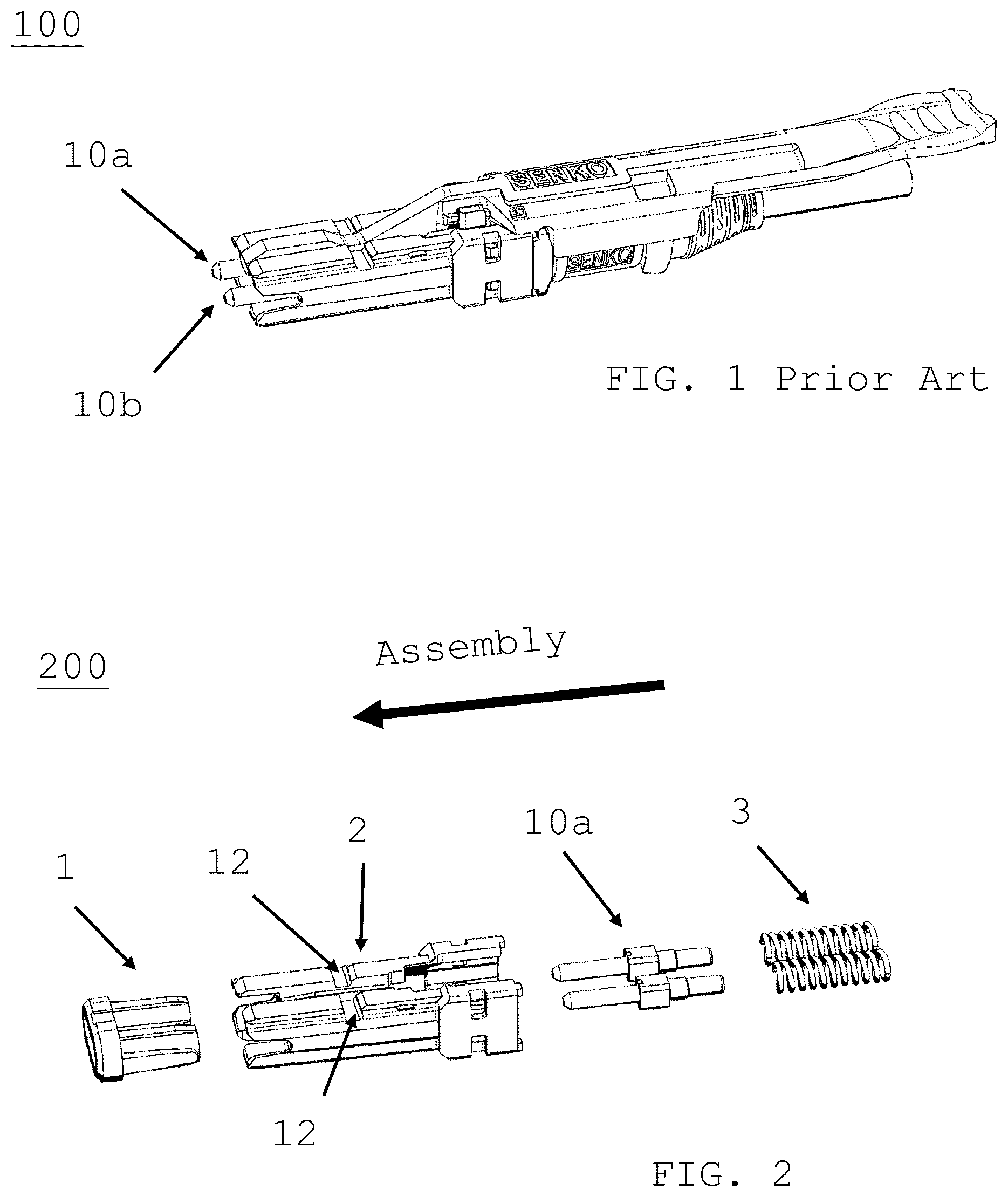
depicts a prior art duplex ferrule connector.
is an exploded view of .
A is a perspective view of an alternative duplex ferrule connector.
is a perspective view of a ferrule assembly according to the present invention.
is a front or proximal view of connector with ferrule assembly.
A is a holder or jog for the connector of .
B is the connector of secured in the holder of A .
C 1 is a top view of A holder.
C 2 is a side view of A holder.
C 3 is a front view of A holder.
C 4 is a view of a hook to secure connector of within holder of C 1 .
is a prior art polishing jig for a single ferrule connector.
A is the connector of with its ferrule end faces polished to APC or 8 degree angle.
B is the connector of after APC polishing.
C is the full insertion of the connector within holder of A .
D is the connector of after APC polishing.
E is a side view and top view of ferrules after APC polishing.
A is a tool to orient the ferrule assembly of after the ferrule is APC polished.
B is an exploded view of a second end of A tool.
is a table of reflection losses by end face polish type depicting reflection loss.
A is A tool secured to ferrule assembly to rotate ferrule after APC polish.
B is rotation step of A .
C depicts removing the tool of A off the ferrule.
D depicts rotating the second ferrule.
A depicts proper orientation of the APC polished ferrules.
B is a side, front perspective view of the ferrules of A .
C depicts bottom view of ferrules after APC polish and orientation.
depicts abutting two APC ferrule end faces to achieve minimal reflection loss.
DETAILED DESCRIPTION
In the following description, apparatuses for mating two multi-fiber optic ferrules. The ferrules end face being formed of an APC cut, as shown in . It will be apparent to those skilled in the art that modifications, including additions and/or substitutions may be made without departing from the scope and spirit of the invention. Specific details may be omitted so as not to obscure the invention; however, the disclosure is written to enable one skilled in the art to practice the teachings herein without undue experimentation.
depicts a prior art connector 100 having a plural of ferrule assembly ( 10 a , 10 b ). is an exploded view of connector 100 depicting bias springs 3 , ferrule assembly ( 10 a , 10 b ), connector housing 2 , recess 12 , and a dust cap 1 . A is an alternative duplex ferrule connector 200 with a connector housing 201 , alignment tab 205 and recess 212 . As with connector 100 , connector 200 recess is secured by a latch with holder 500 . Connector 200 has an alignment tab 205 which aids in placement of connector 200 within holder 500 .
depicts a ferrule assembly with a ferrule having an optical fiber therein, and a flange with a pair of opposing slot cut outs ( 11 a . 1 , 11 a . 2 ). depicts an end view or proximal view of connector 100 showing the ferrule assembly 10 a , 10 b and slot cutouts 11 a . 1 , 11 a . 2 and 11 b . 1 , 11 b . 2 respectively. The slot cut outs accept a corresponding protrusion at a second end of a tool as shown in A .
A is a holder or jig that accepts connector 100 in a configuration capable of applying an APC polish to both ferrule end faces at the same time. An APC polish places an 8 degree angle on a flat-end face ferrule. Prior art polishing is one ferrule at a time. The jig holds the connector at an 8 degree angle. The jig is secured to the face of a polishing surface, using a pair of tabs at the base of the holder. B depicts connector 100 in holder 500 . C 1 is a top view of holder 500 . C 2 is a side view of holder 500 . C 3 is a front view of holder 500 .
C 4 depicts a hook comprising a body, holder 500 locking surfaces 114 , and flexible arms 112 . The arms 112 flex upward and are received in a recess 12 of connector upon insertion of connector 100 into holder 500 . locking surfaces 114 aid in securing hook 110 within cut-outs (not shown) within holder.
is a prior art polishing jig 600 with a plural of holders 624 for securing a connector 620 with a single ferrule. By contrast, the present invention is a jig that can hold APC polish two or more ferrules. The jig can be attached to the polisher surface 622 similar to holder 624 .
A depicts connector 100 without an APC polish at the ferrule 10 a . B depicts connector 100 with an APC polish applied to ferrule 10 a ′. C depicts connector 100 within jig 500 prior to applying an APC polish. D is a connector 100 after an APC polish is applied to ferrule 10 a ′. E depicts side view and top view of polish applied to ferrule tip 10 a′.
A is an orienting tool 800 that rotates an APC polished ferrule 10 a ′, at the proximal end of connector 100 . A first end comprises a handle 812 and a second end comprises a tip with a pair of protrusions ( 816 a , 816 b ), connected by shaft 814 . B is an exploded view of tip showing the protrusions.
depicts various ferrule end face cuts, and a table of estimated reflection loss in decibels when two ferrules with the same end cut are opposing each other in an adapter. A more negative decibel means less power loss.
A depicts tool 800 inserted in the direction “I” and secured to ferrule assembly 10 a . The tool protrusions ( 816 a , 816 b ) engage slot cuts ( 11 a . 1 , 11 a . 2 ) at the proximal end “P”, and user pushes the ferrule assembly in a distal direction and rotates (“R”) the ferrule assembly 10 a ′, by 90 degrees, in B . In C , the tool 800 is withdrawn proximally, and spring 3 a biases ferrule assembly forward (“RM”) in connector housing 2 . D depicts using tool 800 to rotate the second ferrule assembly ( 10 b ′) 90 degrees. After both ferrule assembly ( 10 a ′, 10 b ′) are rotated 90 degrees, the APC cut ferrule end faces are in a proper orientation as shown by A . B depicts side view of polished ferrules to an APC angle of 8 degrees of A . C depicts bottom view of APC ferrules after orientation using tool 800 . depicts abutting or inserting of a two connectors 100 after APC polish in an adapter (not shown). shows how the APC polished end faces will abut with no air gap to reduce reflection loss, as estimated in .
An ordinarily skilled person in the art can appreciate that by following the principal of the present invention, a version of the adapter for mating a multi-fiber optic ferrule with another multi-fiber optic ferrule can be derived without departing from the scope and spirit of the invention. Although the embodiments of the present invention described herein are related to multi-fiber optic applications, the present invention can be adapted to single fiber optic applications. Specific details may be omitted so as not to obscure the invention; however, the disclosure is written to enable one skilled in the art to practice the teachings herein without undue experimentation.
The foregoing description of the present invention has been provided for the purposes of illustration and description. It is not intended to be exhaustive or to limit the invention to the precise forms disclosed. Many modifications and variations will be apparent to the practitioner skilled in the art.
The embodiments were chosen and described in order to best explain the principles of the invention and its practical application, thereby enabling others skilled in the art to understand the invention for various embodiments and with various modifications that are suited to the particular use contemplated.
Figures (12)
Citations
This patent cites (317)
- US3721945
- US4150790
- US4327964
- US4478473
- US4762388
- US4764129
- US4840451
- US4872736
- US4979792
- US5026138
- US5041025
- USD323143
- US5212752
- US5265181
- US5289554
- US5317663
- US5335301
- US5348487
- US5418875
- US5444806
- US5481634
- US5506922
- US5521997
- US5570445
- US5588079
- US5602951
- US5684903
- US5687268
- US5781681
- US5845036
- US5915987
- US5937130
- US5956444
- US5971626
- US6041155
- US6049040
- US6095862
- US6134370
- US6178283
- USRE37080
- US6206577
- US6206581
- US6227717
- US6238104
- US6240228
- US6247849
- US6250817
- US6276840
- US6364537
- US6379052
- US6422759
- US6450695
- US6461054
- US6471412
- US6478472
- US6485194
- US6530696
- US6551117
- US6565262
- US6579014
- US6585194
- US6634796
- US6634801
- US6648520
- US6668113
- US6682228
- US6685362
- US6695486
- US6811321
- US6854894
- US6869227
- US6872039
- US6935789
- US7036993
- US7052186
- US7077576
- US7090407
- US7091421
- US7111990
- US7113679
- USD533504
- USD534124
- US7150567
- US7153041
- US7198409
- US7207724
- USD543124
- USD543146
- US7258493
- US7264402
- US7281859
- USD558675
- US7315682
- US7325976
- US7325980
- US7329137
- US7331718
- US7354291
- US7371082
- US7387447
- US7390203
- USD572661
- US7431604
- US7463803
- US7465180
- US7473124
- US7510335
- US7513695
- US7540666
- US7561775
- US7588373
- US7591595
- US7594766
- US7641398
- US7695199
- US7699533
- US7712970
- US7824113
- US7837395
- USD641708
- US8083450
- US8152385
- US8186890
- US8192091
- US8202009
- US8221007
- US8251733
- US8267595
- US8270796
- US8408815
- US8465317
- US8534928
- US8556645
- US8559781
- US8622634
- US8636424
- US8651749
- US8676022
- US8678670
- US8727638
- US8770863
- US9052474
- US9250402
- US9310569
- US9366829
- US9411110
- US9448370
- US9465172
- US9494744
- US9548557
- US9551842
- US9557495
- US9568686
- US9581768
- US9599778
- US9658409
- US9684130
- US9684136
- US9684313
- US9709753
- US9778425
- US9829644
- US9829645
- US9829653
- US9869825
- US9880361
- US9946035
- US9971103
- US10031296
- US2002/0168148
- US2002/0172467
- US2002/0191919
- US2003/0053787
- US2003/0063862
- US2003/0157825
- US2004/0052473
- US2004/0109646
- US2004/0136657
- US2004/0141693
- US2004/0161958
- US2004/0234209
- US2004/0247252
- US2005/0111796
- US2005/0141817
- US2006/0013539
- US2006/0089049
- US2006/0127025
- US2006/0160429
- US2006/0193562
- US2006/0269194
- US2006/0274411
- US2007/0025665
- US2007/0028409
- US2007/0079854
- US2007/0098329
- US2007/0149062
- US2007/0230874
- US2007/0232115
- US2007/0243749
- US2008/0008430
- US2008/0044137
- US2008/0069501
- US2008/0101757
- US2008/0226237
- US2008/0267566
- US2009/0022457
- US2009/0028507
- US2009/0047818
- US2009/0092360
- US2009/0176401
- US2009/0196555
- US2009/0214162
- US2009/0220197
- US2009/0220200
- US2009/0290839
- US2009/0290938
- US2010/0034502
- US2010/0054668
- US2010/0092136
- US2010/0247041
- US2010/0061069
- US2010/0284656
- US2010/0322561
- US2011/0044588
- US2011/0131801
- US2011/0155810
- US2011/0177710
- US2011/0239220
- US2012/0099822
- US2012/0155810
- US2012/0189260
- US2012/0237177
- US2012/0269485
- US2012/0301080
- US2013/0019423
- US2013/0071067
- US2013/0089995
- US2013/0094816
- US2013/0121653
- US2013/0170797
- US2013/0183012
- US2013/0216185
- US2013/0259429
- US2013/0308915
- US2013/0322825
- US2014/0016901
- US2014/0023322
- US2014/0050446
- US2014/0056562
- US2014/0133808
- US2014/0219621
- US2014/0226946
- US2014/0241644
- US2014/0241678
- US2014/0241688
- US2014/0334780
- US2014/0348477
- US2014/0370021
- US2015/0003788
- US2015/0111417
- US2015/0198766
- US2015/0212282
- US2015/0241644
- US2015/0301294
- US2015/0331201
- US2015/0355417
- US2015/0378113
- US2016/0131849
- US2016/0138343
- US2016/0172852
- US2016/0178852
- US2016/0291262
- US2016/0195682
- US2016/0259135
- US2016/0266326
- US2016/0320572
- US2016/0349458
- US2016/0370545
- US2017/0003458
- US2017/0205587
- US2017/0205590
- US2017/0205591
- US2017/0212316
- US2017/0276887
- US2017/0277059
- US2017/0343740
- US2018/0156988
- US2018/0172923
- US2019/0250344
- US2495693
- US2836038
- US201383588
- US2026500189
- US202006011910
- US102006019335
- US1074868
- US1211537
- US1245980
- US1566674
- US1245980
- US1566674
- US2111240
- US2111240
- US2009229545
- US2009276493
- US200821653
- US2001/079904
- US2004/027485
- US2008/112986
- US2009/135787
- US2010/024851
- US2012/136702
- US2012/162385
- US2014/028527
- US2014/182351
- US2015/191024
- US2015/148741