Abstract
To provide a medical needle capable of preventing malfunction of a movement mechanism at the time of use, and improving safety even further. A medical needle 1 A includes: a needle portion 10 ; a case 20 which is capable of exposing a needle tip of the needle portion 10 from a distal end, and is capable of accommodating the needle portion 10 ; a movement mechanism M which moves the needle portion 10 inside the case 20 ; an operation portion 62 for operating the movement mechanism; and an operation regulation portion 80 A that regulates operation of the operation portion 62.
Claims (9)
1. A medical needle, comprising: a needle portion; a case which is capable of exposing a needle tip of the needle portion from a distal end, and is capable of accommodating the needle portion; a movement mechanism which moves the needle portion inside the case until the needle tip protruding from the case is accommodated inside the case; an operation portion for operating the movement mechanism, configured to allow a pressing operation in a pressing operation direction perpendicular to a movement direction of the needle portion when the needle portion is moved by the movement mechanism; an operation member which is included in the movement mechanism and in which the operation portion is integrally formed; an operation regulation portion that regulates the pressing operation of the operation portion; and an engaging portion that is engaged with the operation regulation portion in the movement direction of the needle portion and overlaps the operation regulation portion in the pressing operation direction, wherein: the medical needle has an elongated shape in a longitudinal direction in which the needle portion extends, and, in the longitudinal direction, a side to which the needle tip protrudes is a distal end side and a side opposite the side to which the needle tip protrudes is a proximal end side, the case comprises: a first opening which opens in a direction toward the distal end side and from which the needle portion protrudes; a second opening which is provided at an edge portion of the first opening and opens in a same direction as the first opening; and a flat plate-shaped portion which extends from an end of the second opening in the longitudinal direction, the end of the second opening being positioned at an outside with respect to the edge portion in a radial direction of the first opening, an end portion at the distal end of the flat plate-shaped portion is configured to function as the engaging portion and includes a flat surface portion extending in parallel with the longitudinal direction at an outside in the radial direction of the end portion at the distal end of the flat plate-shaped portion, an end portion at the distal end of the operation member is provided with the operation portion, and the operation portion is provided with the operation regulation portion at the proximal end side of the operation portion, the operation regulation portion is a notch which is formed to be opened to the proximal end side and to be concave in a U-shape along the movement direction of the needle portion, the notch comprising: a first flat surface which is disposed at an outside with respect to the flat plate-shaped portion in the radial direction and extends in parallel with the longitudinal direction; a bottom surface for the U-shape which extends from an end portion at the distal end side of the first flat surface radially inwardly in the pressing operation direction; and a second flat surface which is disposed at an inside with respect to the flat plate-shaped portion in the radial direction and extends in parallel with the first flat surface in the longitudinal direction from an end portion at the distal end side of the bottom surface toward the proximal end side, and the first flat surface is configured to face the flat surface portion from an outside in the radial direction when the end portion at the distal end side of the flat plate-shaped portion is inserted into the notch from the proximal end side such that the operation regulation portion and the engaging portion are engaged in the movement direction of the needle portion and overlap each other in the pressing operation direction, and the first flat surface and the flat surface portion facing each other are configured to directly contact with each other to regulate the pressing operation.
Show 8 dependent claims
2. The medical needle according to claim 1 , wherein the operation regulation portion and the engaging portion are configured so as to be capable of switching between regulation of the pressing operation of the operation portion, and releasing of the regulation of the pressing operation of the operation portion.
3. The medical needle according to claim 1 , wherein the operation portion causes the movement mechanism to operate due to the pressing operation of the operation portion to displace from a predetermined position, and the operation regulation portion and the engaging portion are located in a displacement direction of the operation portion, and regulate the displacement of the operation portion.
4. The medical needle according to claim 1 , wherein the operation regulation portion and the engaging portion regulate the pressing operation of the operation portion in a state where the needle tip is protruding from the case.
5. The medical needle according to claim 1 , wherein: the movement mechanism includes a biasing member that biases the operation member toward the proximal end side to maintain the engagement of the operation regulation portion and the engaging portion by a force of the biasing member.
6. The medical needle according to claim 5 , wherein: the biasing member is disposed between an inner surface of the case on the distal end side and a surface of the operation member on the distal end side, the operation member is movable toward the distal end side relative to the case against the force of the biasing member and configured to cause release of the engagement of the operation regulation portion and the engaging portion to cause release of the regulation of the pressing operation of the operation portion by the operation regulation portion when the operation member moves toward the distal end side.
7. The medical needle according to claim 1 , further comprising, a securing portion that is separate from the operation member and to which the needle portion is secured, wherein the operation member is disposed on an outer circumference of the securing member and moves integrally with the securing member.
8. The medical needle according to claim 1 , wherein the operation member is configured to cause release of the regulation of the pressing operation of the operation portion by the operation regulation portion when the operation member moves toward the distal end side to cause withdrawal of the end portion at the distal end side of the flat plate-shaped portion from the notch and cause release of the engagement of the operation regulation portion and the engaging portion.
9. The medical needle according to claim 1 , wherein: the operation member has a plate-shaped portion which extends continuously to the second flat surface and in a same direction as the second flat surface, and the plate-shaped portion is configured such that, in an engagement state where the operation regulation portion and the engaging portion are engaged, an entirety of a surface at an outer side in the radial direction in the plate-shaped portion contacts a surface at an inner side in the radial direction in the flat plate-shaped portion.
Full Description
Show full text →
CROSS REFERENCE TO RELATED APPLICATIONS
This application is entitled to and claims the benefit of U.S. provisional application Ser. No. 63/014,737 filed on Apr. 24, 2020, the disclosure of which is incorporated herein by reference in its entirety.
TECHNICAL FIELD
The present invention relates to a medical needle.
BACKGROUND ART
Conventionally, as a medical needle used for blood sampling, blood transfusion, infusion, and the like, a type of medical needle is known that pulls the needle tip into a cylindrical case by using a spring force (for example, see Patent Literatures 1 and 2). In such a conventional medical needle, it is possible to prevent accidents in which users (such as medical workers and the patients themselves) are accidentally punctured by the medical needle after withdrawal of the needle (so-called accidental puncturing). It is also possible to prevent scattering of the blood remaining on the needle tip or inside the needle.
CITATION LIST
Patent Literature
•
• Patent Literature 1: National Publication of International Patent Application No. 2002-539897 • Patent Literature 2: Japanese Unexamined Patent Application Publication No. 2019-155097
SUMMARY OF THE INVENTION
Problems to be Solved by the Invention
However, the medical needle disclosed in Patent Literature 2 has a configuration in which the needle tip is pulled inside the case by operating (pressing) an operation portion, which causes a movement mechanism to operate. The needle tip is covered with a cap before use, and in this state, for example, the operation portion is also covered with the cap to prevent malfunction of the movement mechanism. On the other hand, because the cap is detached during use, it is possible to operate the operation portion. If the operation portion is erroneously operated at the time of puncturing or during blood sampling, there is a problem that the movement mechanism malfunctions and causes the needle tip to be accommodated inside the case.
An object of the present invention is to provide a medical needle which is capable of preventing malfunction of the movement mechanism during use, and improving safety even further.
Means of Solving the Problems
A medical needle according to an aspect of the present invention includes: a needle portion; a case which is capable of exposing a needle tip of the needle portion from a distal end, and is capable of accommodating the needle portion; a movement mechanism which moves the needle portion inside the case until the needle tip protruding from the case is accommodated inside the case; an operation portion for operating the movement mechanism, configured to allow a pressing operation in a pressing operation direction perpendicular to a movement direction of the needle portion when the needle portion is moved by the movement mechanism; an operation member which is included in the movement mechanism and in which the operation portion is integrally formed; an operation regulation portion that regulates the pressing operation of the operation portion; and an engaging portion that is engaged with the operation regulation portion in the movement direction of the needle portion and overlaps the operation regulation portion in the pressing operation direction, wherein: the medical needle has an elongated shape in a longitudinal direction in which the needle portion extends, and, in the longitudinal direction, a side to which the needle tip protrudes is a distal end side and a side opposite the side to which the needle tip protrudes is a proximal end side, the case comprises: a first opening which opens in a direction toward the distal end side and from which the needle portion protrudes; a second opening which is provided at an edge portion of the first opening and opens in a same direction as the first opening; and a flat plate-shaped portion which extends from an end of the second opening in the longitudinal direction, the end of the second opening being positioned at an outside with respect to the edge portion in a radial direction of the first opening, an end portion at the distal end of the flat plate-shaped portion is configured to function as the engaging portion and includes a flat surface portion extending in the longitudinal direction at an outside in the radial direction of the end portion at the distal end of the flat plate-shaped portion, an end portion at the distal end of the operation member is provided with the operation portion, and the operation portion is provided with the operation regulation portion at the proximal end side of the operation portion, the operation regulation portion is a notch which is formed to be opened to the proximal end side concave in a U-shape along the movement direction of the needle portion, the notch comprising: a first flat surface which is disposed at an outside with respect to the flat plate-shaped portion in the radial direction and extends in the longitudinal direction; a bottom surface for the U-shape which extends from an end portion at the distal end side of the first flat surface inwardly in the pressing operation direction; and a second flat surface which is disposed at an inside with respect to the flat plate-shaped portion in the radial direction and extends in parallel with the first flat surface in the longitudinal direction from an end portion at the distal end side of the bottom surface toward the proximal end side, and the first flat surface is configured to face the flat surface portion from an outside in the radial direction when the end portion at the distal end side of the flat plate-shaped portion is inserted into the notch from the proximal end side such that the operation regulation portion and the engaging portion are engaged in the movement direction of the needle portion and overlap each other in the pressing operation direction, and the first flat surface and the flat surface portion facing each other are configured to directly contact with each other to regulate the pressing operation.
Effects of the Invention
According to the medical needle of the present invention, it is possible to prevent malfunction of the movement mechanism during use, and to improve safety even further.
BRIEF DESCRIPTION OF THE DRAWINGS
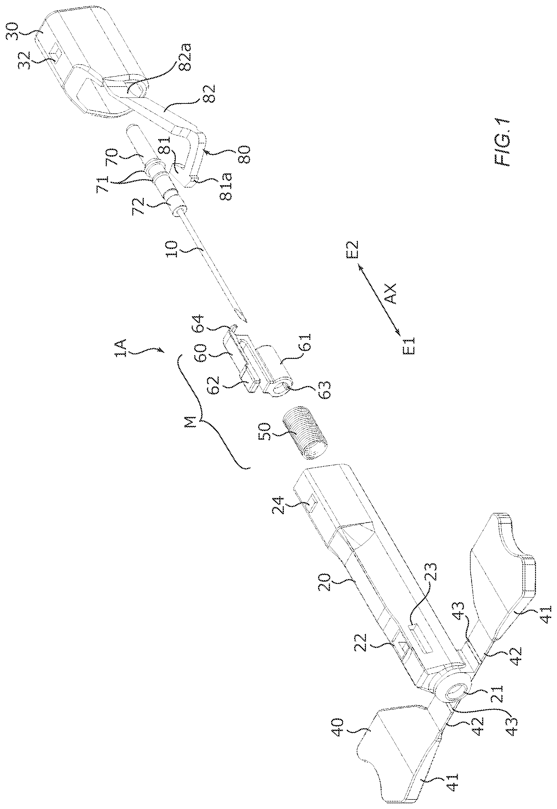
is an exploded perspective view of a medical needle according to a first embodiment as viewed from the distal end side.
is an exploded perspective view of the medical needle according to the first embodiment as viewed from the rear end side.
A and 3 B are perspective views showing a state of the medical needle after assembling each of the members.
A and 4 B are cross-sectional views showing a state of the medical needle after assembling each of the members.
A and 5 B are perspective views showing a state of the medical needle after the operation regulation portion is press-fitted inside the case.
A and 6 B are cross-sectional views showing a state of the medical needle after the operation regulation portion is press-fitted inside the case.
A and 7 B are cross-sectional views showing a state after operation regulation of the medical needle is released.
A and 8 B are cross-sectional views showing a state of the medical needle after accommodating the needle portion.
is a perspective view of a medical needle according to a second embodiment.
A and 10 B are cross-sectional views of the main parts of the medical needle according to the second embodiment.
A and 11 B are cross-sectional views of the main parts of a medical needle according a modification.
MODE FOR CARRYING OUT THE INVENTION
Hereinafter, embodiments of the present invention will be described in detail with reference to the drawings.
In the present embodiments, for example, medical needles 1 A and 1 B (so-called winged needles), which are used by being secured following puncturing of the patient's skin at the time of blood sampling, blood transfusion, infusion, and the like, will be described as examples of the present invention. The medical needles 1 A and 1 B have a configuration in which the needle tip is pulled inside a case by using a spring force.
First Embodiment
and are exploded perspective views of a medical needle 1 A according to a first embodiment. In the description below, the side on which the needle tip protrudes in a longitudinal direction AX is referred to as the “distal end E 1 ”, and the opposite side is referred to as the “proximal end E 2 ”. Furthermore, a state where a predetermined length of the needle tip is protruding from the case 20 is referred to as the “first state”. A state where the needle tip is accommodated inside the case 20 is referred to as the “second state”.
As shown in and , the medical needle 1 A includes a needle portion 10 , a case 20 , a cover portion 30 , a wing portion 40 , a biasing member 50 , an operation member 60 , a securing portion 70 , and an operation regulation portion 80 A. A case that accommodates the needle portion 10 is formed by the case 20 and the cover portion 30 . Furthermore, the biasing member 50 and the operation member 60 form a movement mechanism M for switching the needle portion 10 from the first state to the second state.
A cap (not shown) is attached to the medical needle 1 A before use so as to cover the needle protruding from the case 20 . The cap is detachably attached so as to cover, for example, a section of the case 20 on the distal end E 1 side (including the upper surface of the operation portion 62 ).
In the medical needle 1 A, the cap, the case 20 , the cover portion 30 , the wing portion 40 , the operation member 60 , the securing portion 70 , and the operation regulation portion 80 A are formed of a plastic material such as polycarbonate or polypropylene.
The needle portion 10 is a hollow needle having a flow path for blood or a drug solution. The needle portion 10 is made of a metallic material such as stainless steel, aluminum, aluminum alloy, titanium, or titanium alloy. The end portion of the needle portion 10 on the proximal end E 2 side (the end portion on the opposite side to the needle tip) is secured to the securing portion 70 by adhesion or the like, and is connected to a tube (not shown). The needle portion 10 may be made of a material other than a metallic material, such as a resin material.
The case 20 has a cylindrical shape which is open at both ends, and a space for accommodating the needle portion 10 and the movement mechanism M is formed inside the case 20 along the longitudinal direction AX. For example, a circular opening 21 is provided on the distal end E 1 side of the case 20 . The diameter of the opening 21 is set slightly larger than the outer diameter of the needle portion 10 , and the needle tip is exposed through the opening 21 .
A first engaging portion 22 that engages the operation portion 62 of the operation member 60 in the first state is provided on the upper surface of the case 20 on the distal end E 1 side. The first engaging portion 22 is, for example, a square hole that communicates with the internal space of the case 20 . Furthermore, a second engaging portion 25 that engages with the operation portion 62 of the operation member 60 in the second state is provided on the inner surface of the case 20 on the proximal end E 2 side (see B ). The second engaging portion 25 is, for example, a step provided on the inner surface of the case 20 .
Insertion slits 23 for displaceably inserting the operation regulation portion 80 A into the case 20 are provided on both side surfaces of the case 20 on the distal end E 1 side. Furthermore, locking portions 24 for maintaining an engaged state with the cover portion 30 are provided on the upper surface and the lower surface of the case 20 on the proximal end E 2 side.
The cover portion 30 is a lid member that closes the opening on the proximal end E 2 side of the case 20 . An opening 31 for passing a tube (not shown) connected to the needle portion 10 is provided at the end portion of the cover portion 30 on the proximal end E 2 side. Furthermore, the inner surface of the end portion is provided with a concave portion 33 into which an impact mitigating portion 64 of the operation member 60 enters in the second state (see A and the like). Moreover, the upper surface and the lower surface of the cover portion 30 are provided with engagement holes 32 that engage with the locking portions 24 of the case 20 .
The wing portion 40 is a pair of wing members extending on both sides of the distal end of the case 20 , and, for example, is integrally formed with the case 20 . The wing portion 40 includes a grip portion 41 , and a thin-walled portion 42 formed thinner than the grip portion 41 . The grip portion 41 is configured to be rotatable by a predetermined angle about a groove 43 formed in the thin-walled portion 42 .
The biasing member 50 is a member that exerts a biasing force to an extent that causes the operation member 60 to be pressed against the proximal end E 2 side of the cover portion 30 in the second state. The biasing member 50 is, for example, configured by a metallic compression coil spring, and is arranged on a section 72 on the distal end E 1 side of the securing portion 70 .
The operation member 60 includes a joint portion 61 and an operation portion 62 .
The joint portion 61 has, for example, a circular tube shape. The inner surface of the joint portion 61 on the distal end E 1 side is formed having a smaller diameter than the section on the proximal end E 2 side, and a groove 63 is provided along the longitudinal direction AX.
The operation portion 62 is an operation lever for releasing the engagement between the case 20 and the operation member 60 (movement mechanism M) when the needle portion 10 is accommodated inside the case 20 . The operation portion 62 is, for example, arranged on the outer surface of the joint portion 61 , and is formed in a substantially letter-U shape along the longitudinal direction AX. The free end of the operation portion 62 has a bulging shape that can engage with the first engaging portion 22 and the second engaging portion 25 of the case 20 .
The operation portion 62 functions as a leaf spring that bends in response to an external force applied to the free end, and exerts a restoring force (biasing force). The operation portion 62 is provided, for example, so that the separation distance from the joint portion 61 increases from the base of the letter-U shape toward the free end. As a result, when the operation member 60 is arranged inside the case 20 , an upward biasing force is generated in the operation portion 62 , and the engaged state with the first engaging portion 22 or the second engaging portion 25 is maintained. On the other hand, in the first state, when the operation portion 62 is downwardly pressed against the biasing force, the engaged state with the first engaging portion 22 is released.
Further, an impact mitigating portion 64 for mitigating the impact when switching from the first state to the second state is provided on the proximal end E 2 side of the operation portion 62 . The impact mitigating portion 64 is formed, for example, having a curved shape that hangs down from the end portion of the operation portion 62 on the proximal end E 2 side. The impact mitigating portion 64 absorbs an impact by becoming more curved when a force greater than or equal to a predetermined force is applied.
The securing portion 70 is, for example, a circular tubular member into which the end portion of the needle portion 10 on the proximal end E 2 side is inserted and secured. The outer surface of the securing portion 70 is provided with two flange portions 71 , which are arranged side by side at a substantially central position in the longitudinal direction. Furthermore, a ridge (reference numeral omitted) that corresponds to the groove 63 of the joint portion 61 is provided along the longitudinal direction AX on the lower side of outer surface of the securing portion 70 .
The securing portion 70 is inserted into the joint portion 61 of the operation member 60 from the proximal end E 2 side. The securing portion 70 is inserted while engaging the ridge with the groove 63 of the joint portion 61 . A small-diameter section of the joint portion 61 is fitted between the two flange portions 71 as a result of the flange portion 71 on the distal end E 1 side being pushed in until it clears the end surface of the joint portion 61 on the proximal end E 2 side. Furthermore, the biasing member 50 is attached to the section 72 of the securing portion 70 which is exposed from the joint portion 61 .
The operation regulation portion 80 A regulates pressing operations made with respect to the operation portion 62 . In the present embodiment, the operation regulation portion 80 A includes an arm 82 , which protrudes in a letter-L shape from the end portion of the cover portion 30 on the distal end E 1 side, and a head 81 provided on the free end of the arm 82 . The head 81 and a section of the arm 82 on the head 81 side are inserted into the case 20 from the insertion slit 23 . In the present embodiment, the operation regulation portion 80 A is integrally formed with the cover portion 30 .
In a state where the medical needle 1 A is assembled, the head 81 is a section which is located between the joint portion 61 and the operation portion 62 of the operation member 60 . The head 81 includes a slit engaging portion 81 a , and the edge of the insertion slit 23 and the slit engaging portion 81 a become engaged when the head 81 is press-fitted into the insertion slit 23 of the case 20 .
The arm 82 includes a spring portion 82 a that functions as a leaf spring on the section which is connected to the cover portion 30 . The spring portion 82 a bends in response to an external force applied to the arm 82 , and exerts a restoring force (biasing force). The spring portion 82 a is formed, for example, by bending the distal end E 1 side of the arm 82 so that it becomes separated from the case 20 . As a result, when the arm 82 is pressed toward the case 20 side, a biasing force is generated in the opposite direction to the pressing direction.
For example, the medical needle 1 A is assembled as follows. First, the movement mechanism M comprising the biasing member 50 and the operation member 60 is attached to the needle portion 10 . Specifically, the operation member 60 and the biasing member 50 are inserted through from the needle tip in a state where the needle portion 10 is secured by the securing portion 70 . Then, the needle portion 10 , the securing portion 70 , and the movement mechanism M are inserted into the case 20 so that the needle tip protrudes from the opening 21 , and press-fitted up to a position where the first engaging portion 22 of the case 20 and the operation portion 62 of the operation member 60 become engaged. Then, the cover portion 30 is attached to the proximal end E 2 side of the case 20 .
The first state is maintained as a result of the first engaging portion 22 of the case 20 and the operation portion 62 of the operation member 60 being engaged. At this time, the biasing member 50 is arranged in a state where it is compressed in the internal space of the case 20 . The edge of the biasing member 50 on the distal end E 1 side makes contact with the inner surface of the case 20 on the distal end side, and the edge on the proximal end E 2 side makes contact with the end surface of the operation member 60 on the distal end E 1 side (see B ).
The state of the medical needle 1 A after assembling each of the members as described above is shown in A , B , A , and B . A and B are perspective views of the medical needle 1 A. B omits the case 20 and the wing portion 40 . Furthermore, A is a cross-sectional view taken along line B-B in B . B is a cross-sectional view taken along line A-A in A .
After assembling each of the members, the arm 82 is in an unloaded state. As a result, the operation regulation portion 80 A is arranged outside the case 20 as shown in A and the like. In this state, the arm 82 is pressed toward the case 20 side, and the head 81 is press-fitted into the insertion slit 23 due to a change in shape of the arm 82 .
The state of the medical needle 1 A after press-fitting the operation regulation portion 80 A inside the case 20 is shown in A , B , A , and B . A and B are perspective views of the medical needle 1 A. B omits the case 20 and the wing portion 40 . Furthermore, A is a cross-sectional view taken along line B-B in B . B is a cross-sectional view taken along line A-A in A .
After press-fitting the operation regulation portion 80 A, the arm 82 is in a state where it is biased in the opposite direction to the pressing direction. As a result, the operation regulation portion 80 A tries to restore a state where the arm 82 is not press-fitted (such as A ). However, because the slit engaging portion 81 a of the head 81 engages with the edge of the insertion slit 23 of the case 20 , further restoration is inhibited, and the state in which the operation regulation portion 80 A is press-fitted inside the case 20 is maintained. At this time, the head 81 is downwardly positioned in the displacement direction of the operation portion 62 , that is to say, between the operation portion 62 and the joint portion 61 , and pressing operations made with respect to the operation portion 62 are regulated. Furthermore, the arm 82 is in a state where it is separated from the case 20 , and the regulation by the operation portion 62 can be released by pressing the arm 82 further toward the case 20 side. That is to say, the operation regulation portion 80 A is configured so as to be capable of switching between regulation of operation of the operation portion 62 , and releasing of the regulation.
The state shown in A and the like is the initial state of the medical needle 1 A. The medical needle 1 A is stored by attaching a cap to the needle tip when not in use. When the medical needle 1 A is used, the cap is detached to expose the needle tip. Then, the patient's skin is punctured by the needle portion 10 while the grip portion 41 of the wing portion 40 is being gripped. After the puncture is made, the grip portion 41 is expanded and taped down as necessary.
At this time, although the operation portion 62 is exposed, pressing operations are disabled by the operation regulation portion 80 A. Therefore, at the time of use, it is possible to reliably prevent the operation portion 62 from being pressed and the movement mechanism M from malfunctioning, against the user's intent.
When the needle tip is withdrawn from the patient's skin, the operation regulation of the operation regulation portion 80 A is released. Specifically, as shown in A and B , the arm 82 is pressed toward the case 20 side, and the head 81 is shifted to a position which is displaced from below the operation portion 62 . As a result, pressing operations can be made with respect to the operation portion 62 .
When the operation portion 62 of the operation member 60 is pressed in this state, as shown in A and B , the movement mechanism M operates due to the action of the biasing member 50 , and the operation member 60 , the securing portion 70 , and the needle portion 10 move toward the proximal end E 2 side. As a result, the needle tip which is exposed from the case 20 is accommodated inside the case 20 . Therefore, it is possible to prevent accidental puncturing after withdrawal of the needle, and scattering of the blood remaining on the needle tip or inside the needle portion 10 .
At this time, the action of the impact mitigating portion 64 mitigates the impact caused by the contact between the impact mitigating portion 64 and the cover portion 30 , and the generation of collision noises is also suppressed. Furthermore, the operation regulation portion 80 A returns to a state which is equivalent to the initial state shown in A and the like.
Note that the needle portion 10 may be accommodated inside the case 20 by pressing the operation portion 62 after the needle tip has firstly been withdrawn from the patient's skin.
Second Embodiment
is a perspective view of a medical needle 1 B according to a second embodiment. A and 10 B are cross-sectional views of the main parts of the medical needle 1 B. A shows a state where operation of the operation portion 62 is regulated. B shows a state where the operation regulation of the operation portion 62 is released. In the medical needle 1 B, the configurations of the operation portion and the operation regulation portion are different to those of the medical needle 1 A according to the first embodiment; and the rest of the configuration is substantially equivalent to the medical needle 1 A. That is to say, the medical needle 1 B includes a needle portion 10 , a case 20 , a cover portion 30 , a wing portion 40 , a biasing member 50 , an operation member 60 , a securing portion 70 , and an operation regulation portion 80 B.
In the medical needle 1 B, the operation portion 62 is arranged such that it protrudes from the case 20 toward the distal end E 1 side. Before use, the rear end portion of a cap C, which is attached so as to cover the needle tip, enters between the operation portion 62 and the distal end portion of the case 20 (the section provided with the opening 21 ), which regulates pressing operations made with respect to the operation portion 62 .
Furthermore, the operation regulation portion 80 B is formed on the end portion of the operation portion 62 on the proximal end E 2 side so as to extend in a letter-J shape. In the first state, the operation portion 62 is biased toward the proximal end E 2 side. Further, the operation regulation portion 80 B engages with the edge of the case 20 . At this time, a space is provided between the end surface of the joint portion 61 on the distal end E 1 side and the end surface of the distal end portion of the case 20 so that the operation portion 62 can be relatively moved toward the distal end E 1 side (and the case 20 toward the proximal end E 2 side). As a result, the biasing member 50 is in a state where it is capable of being compressed even more.
In the medical needle 1 B, for example, by moving the case 20 toward the proximal end E 2 side and relatively moving the operation portion 62 toward the distal end E 1 side with respect to the case 20 , the engagement between the operation portion 62 and the case 20 is released, and the operation portion 62 is in pressable state (see B ). Furthermore, in the medical needle 1 B, the operation regulation of the operation portion 62 can be carried out with a simpler structure than that of the medical needle 1 A of the first embodiment.
As described above, the medical needles 1 A and 1 B each include: a needle portion 10 ; a case 20 which is capable of exposing the needle tip of the needle portion 10 from the distal end E 1 , and is capable of accommodating the needle portion 10 inside the case 20 ; a movement mechanism M which moves the needle portion 10 inside the case 20 until the needle tip protruding from the case 20 is accommodated inside the case 20 ; an operation portion 62 for operating the movement mechanism M; and operation regulation portions 80 A and 80 B that regulate operation of the operation portion 62 .
According to the medical needles 1 A and 1 B, operation of the operation portion 62 is regulated by the operation regulation portions 80 A and 80 B. More specifically, even in a state where the cap C has been detached and the needle tip of the needle portion 10 is protruding from the case 20 , operation of the operation portion 62 is regulated by the operation regulation portions 80 A and 80 B. Consequently, the operation portion 62 cannot be easily operated regardless of the presence or absence of the cap C. Consequently, malfunction of the movement mechanism M that moves the needle portion 10 during use can be prevented, and the safety can be improved even further.
Furthermore, the operation regulation portions 80 A and 80 B are configured so as to be capable of switching between regulation of operation of the operation portion 62 , and releasing of the regulation. As a result, the state in which operation of the operation portion 62 is regulated can be easily released. Therefore, the movement mechanism M can be operated without requiring complicated operations.
Moreover, the operation portion 62 causes the movement mechanism M to operate due to an operation to displace from a predetermined position. Further, the operation regulation portions 80 A and 80 B are located in a displacement direction of the operation portion 62 , and regulate the displacement of the operation portion 62 . As a result, operation of the operation portion 62 is physically regulated. Therefore, malfunction of the movement mechanism M during use can be reliably prevented.
The invention made by the present inventors has been specifically described above based on the embodiments. However, the present invention is not limited to the above embodiments, and can be changed without departing from the spirit of the present invention.
(Modifications)
A and 11 B are cross-sectional views of the main parts of a medical needle 1 C according to a modification of the first embodiment. A shows a state where operation of the operation portion 62 is regulated. B shows a state where an operation regulation of the operation portion 62 is released.
In the medical needle 1 C, the operation regulation portion 80 B according to the second embodiment is provided in addition to the operation regulation portion 80 A according to the first embodiment, and operation regulation of the operation portion 62 is carried out in two stages. That is to say, in the medical needle 1 C, the arm 82 is pressed toward the case 20 side, and the head 81 is shifted to a position which is displaced from below the operation portion 62 . In addition, the operation portion 62 is in a pressable state only after the case 20 has been moved toward the proximal end E 2 side (see B ). Therefore, in the medical needle 1 C according to the modification, malfunction of the movement mechanism M during use can be more reliably prevented.
Furthermore, for example, the operation regulation portion is not limited to the configurations described in the embodiments and in the modification, and a rotary lock mechanism may be used.
Moreover, the operation regulation portion may have any function that regulates operation of the operation portion. For example, the regulated state may be released as a result of a pressing force of the operation portion, for example by way of a bubble wrap material. In addition, for example, the operation regulation portion may be configured such that it cannot be easily operated by increasing the rigidity of the operation portion itself.
Furthermore, in the above embodiments, cases have been illustrated and described where a compression coil spring is used as the biasing member 50 , and the compression coil spring is arranged on the distal end E 1 side of the operation member 60 . However, for example, a tension coil spring may be arranged on the proximal end E 2 side of the operation member 60 . Also, as the biasing member 50 , rubber or the like may be applied instead of a spring.
In the above embodiments, a winged needle which is used by being secured following puncturing of a patient's skin has been illustrated and described. However, the present invention is not limited to this. For example, the present invention can be applied to an indwelling needle or the like used when carrying out a continuous intravenous drip infusion.
The embodiments disclosed above are to be considered illustrative in all respects, and are not intended to be restrictive. The scope of the present invention is defined by the scope of claims, and not by the description above. It is intended that all modifications that fall within the meaning and scope equivalent to the scope of claims be included.
DESCRIPTION OF REFERENCE NUMERALS
•
• 1 A, 1 B, 1 C Medical needle • 10 Needle portion • 20 Case • 50 Biasing member • 60 Operation member • 62 Operation portion • 70 Securing portion • 80 A, 80 B Operation regulation portion • M Movement mechanism • 21 a Edge portion • 26 Second opening • 27 Flat plate-shaped portion • 27 a Flat surface portion • 60 a Plate-shaped portion • 80 B 1 First flat surface • 80 B 2 Second flat surface • 80 B 3 Bottom surface
Figures (11)
Citations
This patent cites (6)
- US6210371
- US7097633
- US2004/0116855
- US2019/0282785
- US2002539897
- US2019155097