Shutter Mechanism, Powder Container, and Developing Device
Abstract
A shutter mechanism includes an opening, an opening and closing part attached to the opening and openable and closable, a first fitting part disposed at one end with reference to a center of the opening in an open direction of the opening and closing part to move in the open direction to make engagement, a second fitting part disposed at another end opposite the one end with reference to the center of the opening to move in the open direction to make engagement, the first fitting part and the second fitting part detachably attached to a powder container containing a powder used to form an image, the first fitting part and the second fitting part used for positioning in a direction intersecting with the open direction, and a butt face orthogonal to the open direction.
Claims (9)
1. A shutter mechanism comprising: an opening; an opening and closing part attached to the opening and openable and closable; a first fitting part disposed at one end with reference to a center of the opening in an open direction of the opening and closing part to move in the open direction to make engagement; a second fitting part disposed at another end opposite the one end with reference to the center of the opening to move in the open direction to make engagement, the first fitting part and the second fitting part detachably attached to a powder container containing a powder used to form an image, the first fitting part and the second fitting part used for positioning in a direction intersecting with the open direction; and a butt face orthogonal to the open direction, the butt face contacting the powder container when the first fitting part and the second fitting part engage with the powder container, the butt face contacting the powder container in a direction parallel to an engaging direction of the first fitting part and the second fitting part, the engaging direction of the first fitting part and the second fitting part parallel to the open direction of the opening and closing part.
4. A developing device comprising: a powder supply path through which powder used to form an image is supplied to a powder container containing the powder; and a shutter mechanism including an opening connected to the powder supply path, and an opening and closing part attached to the opening and openable and closable, the opening and closing part interposed between the powder container and the powder supply path to open and close between the powder supply path and the powder container, the powder container inserted into the developing device in a direction orthogonal to a direction in which the powder supply path extends, the direction in which the powder container is inserted into the developing device parallel to an open direction of the opening and closing part.
9. A shutter mechanism comprising: an opening; an opening and closing part attached to the opening and openable and closable; a first fitting part disposed at one end with reference to a center of the opening in an open direction of the opening and closing part to move in the open direction to make engagement; a second fitting part disposed at another end opposite the one end with reference to the center of the opening to move in the open direction to make engagement, the first fitting part and the second fitting part detachably attached to a gate, the first fitting part and the second fitting part used for positioning in a direction intersecting with the open direction; and a butt face orthogonal to the open direction, the butt face contacting the gate when the first fitting part and the second fitting part engages with the gate, the butt face contacting the gate in a direction parallel to an engaging direction of the first fitting part and the second fitting part, the engaging direction of the first fitting part and the second fitting part parallel to the open direction of the opening and closing part.
Show 6 dependent claims
2. A powder container to which the shutter mechanism according to claim 1 is attached, the powder container comprising: a fixation member to fix the shutter mechanism to the powder container with the butt face contacting the powder container; and a hole formed on the powder container to engage with the fixation member, wherein the hole extends parallel to the open direction.
3. The powder container according to claim 2 , wherein the shutter mechanism is attached to the powder container, and wherein the first fitting part and the second fitting part are separated from the powder container in the open direction with the butt face contacting the powder container.
5. The developing device according to claim 4 , wherein the developing device has a receiving face orthogonal to the open direction of the opening and closing part, and wherein the receiving face contacts the shutter mechanism when the shutter mechanism is attached to the developing device.
6. The developing device according to claim 5 , wherein the receiving face has a hole, and wherein the receiving face is clamped by a screw.
7. The developing device according to claim 6 , wherein the shutter mechanism includes a first fitting part and a second fitting part to position the shutter mechanism when the shutter mechanism is attached to the developing device, and wherein the first fitting part and the second fitting part are disposed at a plurality of different positions in the open direction.
8. The developing device according to claim 4 , further comprising a guide disposed on a side face of the powder supply path extending in the open direction, wherein the guide protrudes from the side face to position the shutter mechanism.
Full Description
Show full text →
CROSS-REFERENCE TO RELATED APPLICATION
This patent application is based on and claims priority pursuant to 35 U.S.C. § 119(a) to Japanese Patent Application No. 2023-042945, filed on Mar. 17, 2023, in the Japan Patent Office, the entire disclosure of which is hereby incorporated by reference herein.
BACKGROUND
Technical Field
Embodiments of the present disclosure relate to a shutter mechanism, a powder container provided with the shutter mechanism, and a developing device provided with the shutter mechanism.
Background Art
In the related art of image forming apparatuses that adopt electrophotography, some technologies or configurations are proposed in which toner is supplied by a granular-material conveyor from a toner bottle, which serves as a granular material container or powder container and contains toner that is a powder or granular material, to a developing device.
Such a toner bottle is arranged in the developing device or the granular-material conveyor in an attachable and detachable manner, and is required to be positioned with a high degree of precision in order to prevent, for example, the leakage of the powder from a supply path when the powder is supplied.
Further, developing devices have been proposed each of which is provided with a shutter mechanism having a sliding shutter to block the port for toner supply of the developing device attachable to and detachable from an image forming apparatus. The developing device has a connecting portion connected to a toner outlet of the image forming apparatus. The connecting portion is fixed to the developing device and the shutter mechanism is arranged downstream from the connecting portion under normal operating conditions such that toner does not leak at the port for toner supply of the developing device even if the developing device is to be detached from the image forming apparatus.
SUMMARY
Embodiments of the present disclosure described herein provide a shutter mechanism including an opening, an opening and closing part attached to the opening and openable and closable, a first fitting part disposed at one end with reference to a center of the opening in an open direction of the opening and closing part to move in the open direction to make engagement, a second fitting part disposed at another end opposite the one end with reference to the center of the opening to move in the open direction to make engagement, the first fitting part and the second fitting part detachably attached to a powder container containing a powder used to form an image, the first fitting part and the second fitting part used for positioning in a direction intersecting with the open direction, and a butt face orthogonal to the open direction. In the shutter mechanism, the butt face contacts the powder container when the first fitting part and the second fitting part engage with the powder container. In the shutter mechanism, the butt face contacts the powder container in a direction parallel to an engaging direction of the first fitting part and the second fitting part. In the shutter mechanism, the engaging direction of the first fitting part and the second fitting part are parallel to the open direction of the opening and closing part.
BRIEF DESCRIPTION OF THE DRAWINGS
A more complete appreciation of embodiments and the many attendant advantages thereof will be readily obtained as the same becomes better understood by reference to the following detailed description when considered in connection with the accompanying drawings.
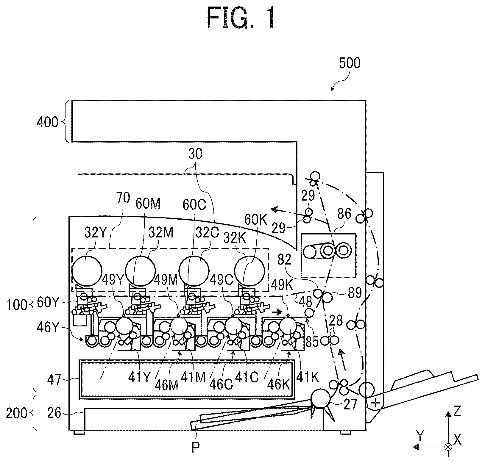
is a diagram illustrating a configuration of an image forming apparatus according to an embodiment of the present disclosure.
is a diagram illustrating a configuration or structure of the developing device of , according to an embodiment of the present disclosure.
is a diagram illustrating the shape of a container used to supply developer to the developing device illustrated in , according to an embodiment of the present disclosure.
is a diagram illustrating a configuration of a developer supply path of the developing device illustrated in .
is a diagram illustrating a configuration or structure of the shutter mechanism illustrated in , according to an embodiment of the present disclosure.
is a diagram illustrating how a shutter mechanism operates when attached to a developing device, according to an embodiment of the present disclosure.
is a diagram illustrating a shutter mechanism removed from a developing device, according to an embodiment of the present disclosure.
is a diagram illustrating a shutter mechanism attached to a developing device, according to an embodiment of the present disclosure.
is a diagram illustrating the relative positions of multiple elements when a shutter mechanism is viewed from a different angle, according to an embodiment of the present disclosure.
A and B are diagrams illustrating how a shutter mechanism is attached, according to a comparative example of the present disclosure.
is a diagram illustrating the relative positions of multiple elements when a shutter mechanism is viewed from a different angle, according to an embodiment of the present disclosure.
A and B are diagrams illustrating how a shutter mechanism having only one fitting part operates, according to a comparative example of the above embodiments of the present disclosure.
A and B are diagrams illustrating how a shutter mechanism having a pair of fitting parts operates, according to an embodiment of the present disclosure.
The accompanying drawings are intended to depict embodiments of the present disclosure and should not be interpreted to limit the scope thereof. The accompanying drawings are not to be considered as drawn to scale unless explicitly noted.
DETAILED DESCRIPTION
The terminology used herein is for the purpose of describing particular embodiments only and is not intended to limit the present disclosure. As used herein, the singular forms “a”, “an”, and “the” are intended to include the plural forms as well, unless the context clearly indicates otherwise. It will be further understood that the terms “includes” and/or “including”, when used in this specification, specify the presence of stated features, integers, steps, operations, elements, and/or components, but do not preclude the presence or addition of one or more other features, integers, steps, operations, elements, components, and/or groups thereof.
In describing example embodiments illustrated in the drawings, specific terminology is employed for the sake of clarity. However, the present disclosure is not intended to be limited to the specific terminology so selected and it is to be understood that each specific element includes all technical equivalents that have the same structure, operate in a similar manner, and achieve a similar result.
Embodiments of the present disclosure are described below step by step with reference to the drawings. In the description of the embodiments, like reference signs are given to elements having similar functionality or configuration, and overlapping description may be omitted where appropriate. The drawings may be simplified or partially omitted to aid the understanding of a particular configuration.
In the following description, the X-axis direction, the Y-axis direction, and the Z-axis direction are perpendicular to each other. The X-axis direction and the Y-axis direction are illustrated as horizontal directions, and the Z-axis direction is illustrated as the vertical direction.
However, no limitation is intended thereby.
is a schematic diagram of an electrophotographic tandem color copier 500 according to an embodiment of the present disclosure. Such an electrophotographic tandem color copier serves as an image forming apparatus and may be referred to simply as a copier 500 in the following description. In the following description, the suffixes Y (yellow), M (magenta), C (cyan), and K (black) that are given to components or elements indicate to what color each of those components or elements corresponds, and may be omitted where appropriate. The copier 500 according to the present embodiment includes a printer unit 100 that is a main unit of the copier in which image forming units 46 Y, 46 M, 46 C, and 46 K are arranged in parallel and form toner images of multiple colors including Y (yellow), M (magenta), C (cyan), and K (black). The image forming units 46 Y, 46 M, 46 C, and 46 K are provided with a plurality of modules that are attachable to and detachable from the printer unit 100 . In an alternative embodiment of the present disclosure, the copier 500 may be a monochrome copier.
Typically, the copier 500 includes the printer unit 100 , a sheet feeder 200 , and a scanner unit 400 arranged above the printer unit 100 . In the following description, the sheet feeder and the scanner unit may be referred to as a sheet feeding table and a document reading device, respectively.
A toner container holder 70 is arranged at an upper portion of the printer unit 100 to hold four detachable and replaceable toner containers 32 Y, 32 M, 32 C, and 32 K that serve as four powder containers and handle multicolor toner including yellow (Y), magenta (M), cyan (C), and black (BK). Under the toner container holder 70 , an intermediate transfer unit 85 is arranged.
The intermediate transfer unit 85 according to the present embodiment includes the intermediate transfer belt 48 that serves as an intermediate transferor, four primary-transfer bias rollers 49 Y, 49 M, 49 C, and 49 K, a secondary-transfer backup roller 82 , a plurality of tension rollers, and an intermediate-transfer cleaning device. The intermediate transfer belt 48 is stretched and supported by the above-described multiple rollers, and is seamlessly moved in the direction indicated by an arrow in as the secondary-transfer backup roller 82 , which is one of the multiple rollers, is driven to rotate.
In the printer unit 100 , four image forming units 46 Y, 46 M, 46 C, and 46 K that handle toner images of yellow, magenta, cyan, and black colors are arranged in parallel, so as to face the intermediate transfer belt 48 . Under the four toner containers 32 Y, 32 M, 32 C, and 32 K, four toner supply devices 60 Y, 60 M, 60 C, and 60 K that serve as powder supply devices corresponding to the toner containers of the respective colors are arranged. The toner supply devices 60 Y, 60 M, 60 C, and 60 K supply the toner that is a powder and is contained in the toner containers 32 Y, 32 M, 32 C, and 32 K to developing devices 50 Y, 50 M, 50 C, and 50 K of the image forming units 46 Y, 46 M, 46 C, and 46 K. In the present embodiment, the four image forming units 46 Y, 46 M, 46 C, and 46 K make up an image forming device.
The printer unit 100 further includes an exposure device 47 as a latent image forming unit below the four image forming units 46 . The exposure device 47 exposes and scans the surfaces of photoconductors 41 Y, 41 M, 41 C, and 41 K, which serve as image bearers as will be described later in detail, based on the image data of document images read by the scanner unit 400 , to form electrostatic latent images on the surfaces of the photoconductors 41 Y, 41 M, 41 C, and 41 K, respectively. The image data may be either read by the scanner unit 400 or input from an external device such as a personal computer connected to the copier 500 . Although the exposure device 47 according to the present embodiment employs laser beam scanning using a laser diode, a different method that employs, for example, a light-emitting diode (LED) array may be adopted.
is a diagram illustrating a schematic configuration of the image forming unit 46 Y that handles the yellow toner image, according to the present embodiment.
The image forming unit 46 Y is provided with a drum-shaped photoconductor 41 Y. In the image forming unit 46 Y, for example, a charging roller 44 Y serving as a charging device, a developing device 50 Y, a photoconductor cleaning device 42 Y to clean the photoconductor 41 Y, and an electric-charge removing device are arranged around the photoconductor 41 Y. A series of image forming processes including a charging process, an exposure process, a developing process, a transfer process, and a cleaning process are performed on the photoconductor 41 Y. As a result, a yellow toner image is formed on the surface of the photoconductor 41 Y.
The other three image forming units 46 M, 46 C, and 46 K have a similar configuration to that of the yellow image forming unit 46 Y except for the color of the toner used therein and form toner images of the respective colors on the photoconductors 41 M, 41 C, and 41 K. In the following description, only the image forming unit 46 Y that handles yellow toner is described, and the description of the other three image forming units 46 M, 46 C, and 46 K are omitted where appropriate.
The photoconductor 41 Y is driven by a drive motor to rotate clockwise in . The surface of the photoconductor 41 Y is evenly charged by the charging roller 44 Y at a position facing the charging roller 44 Y. Such a process I referred to as a charging process. When the photoconductor 41 Y reaches a position to receive the laser beam L emitted from an exposure device 47 , the photoconductor 41 Y is scanned with the laser beam L, and thus an electrostatic latent image for yellow is formed thereon.
Such a process is referred to as an exposure process. Then, the photoconductor 41 Y reaches a position facing the developing device 50 Y, where the electrostatic latent image is developed with yellow toner into a yellow toner image. Such a process is referred to as a developing process.
The four primary-transfer bias rollers 49 Y, 49 M, 49 C, and 49 K of the intermediate transfer unit 85 sandwich the intermediate transfer belt 48 with the corresponding photoconductors 41 Y, 41 M, 41 C, and 41 K, respectively, to form primary transfer nips therebetween. To the primary-transfer bias rollers 49 Y, 49 M, 49 C, and 49 K, a primary transfer bias whose polarity is opposite to the polarity of the electric charge of the toner is applied.
When the surface of the photoconductor 41 Y on which the toner image has been formed in the developing process reaches the position facing the primary-transfer bias roller 49 Y across the intermediate transfer belt 48 , the toner image is transferred from the photoconductor 41 Y onto the intermediate transfer belt 48 in the primary transfer nip.
Such a transferring process is referred to as a primary transferring process. In this step, a small amount of toner remains untransferred on the photoconductor 41 Y. After the toner image is transferred onto the intermediate transfer belt 48 at the primary transfer nip, the surface of the photoconductor 41 Y reaches a position facing the photoconductor cleaning device 42 Y. The untransferred toner remaining on the photoconductor 41 Y is mechanically collected by a cleaning blade 42 a of the photoconductor cleaning device 42 Y at the position facing the photoconductor cleaning device 42 Y (cleaning process). Finally, the surface of the photoconductor 41 Y reaches a position facing the electric-charge removing device, and the residual potential on the photoconductor 41 Y is removed at that position. In this way, a series of image forming processes performed on the photoconductor 41 Y is completed.
Such a series of image forming processes is also performed in the other image forming units 46 M, 46 C, and 46 K in a similar manner to the image forming unit 46 Y that handles yellow toner. In other words, the exposure device 47 disposed below the image forming units 46 M, 46 C, and 46 K irradiates photoconductors 41 M, 41 C, and 41 K of the image forming units 46 M, 46 C, and 46 K with laser beams L based on image data. More specifically, the exposure device 47 includes light sources to emit the laser beams L, a plurality of optical elements, and a polygon mirror that is rotated by a motor. The exposure device 47 uses the optical elements to irradiate the photoconductors 41 M, 41 C, and 41 K with the laser beams L while deflecting the laser beams L with a polygon mirror. Then, after the developing process, the multicolor toner images are transferred from the photoconductors 41 M, 41 C, and 41 K onto the intermediate transfer belt 48 and superimposed on top of one another.
While rotating and moving in the direction indicated by the arrow illustrated in and , the intermediate transfer belt 48 sequentially passes through the primary transfer nips of the primary-transfer bias rollers 49 Y, 49 M, 49 C, and 49 K. Thus, multicolor toner images including yellow, magenta, cyan, and black toner images are primarily transferred from the photoconductors 41 Y, 41 M, 41 C, and 41 K to the intermediate transfer belt 48 on top of one another to form a color toner image on the intermediate transfer belt 48 .
The intermediate transfer belt 48 , to which a color toner image has been formed upon transferring multicolor toner images thereto and superimposing those toner images on top of one another, reaches a position facing a secondary transfer roller 89 arranged opposite the secondary-transfer backup roller 82 . At this position, the secondary-transfer backup roller 82 sandwiches the intermediate transfer belt 48 with the secondary transfer roller 89 to form a secondary transfer nip. The color toner image formed on the intermediate transfer belt 48 is transferred onto a recording medium P such as a transfer sheet conveyed to the position of the secondary transfer nip, for example, by the action of a transfer bias applied to the secondary-transfer backup roller 82 . In such a transferring process, the untransferred toner that failed to be transferred to the recording medium P remains on the intermediate transfer belt 48 . The intermediate transfer belt 48 having passed through the secondary transfer nip reaches the position of an intermediate transfer cleaning device, and untransferred toner on the surface of the intermediate transfer belt 48 is collected. Thus, a series of transfer processes that are performed on the intermediate transfer belt 48 ends.
The movement of the recording medium P is described below. The recording medium P is conveyed from a sheet tray 26 of a sheet feeder 200 arranged below the printer unit 100 to the above-described secondary transfer nip through, for example, a sheet feed roller 27 and a registration roller pair 28 .
More specifically, a plurality of recording media P are stacked and stored in the sheet tray 26 . When the sheet feed roller 27 is driven to rotate counterclockwise in , the uppermost recording medium P is conveyed toward a roller nip formed by two rollers of the registration roller pair 28 .
The recording medium P conveyed to the registration roller pair 28 is temporarily stopped at the position of the roller nip of the registration roller pair 28 that has stopped rotating. The registration roller pair 28 is driven to rotate in accordance with the timing at which the color toner image on the intermediate transfer belt 48 reaches the secondary transfer nip. Accordingly, the recording medium P is conveyed toward the secondary transfer nip.
Thus, a multicolor toner image is transferred onto the recording medium P as desired.
The recording medium P onto which the color toner image has been transferred at the secondary transfer nip is conveyed to the position of a fixing device 86 . In the fixing device 86 , the color toner image transferred to the surface of the recording medium P is fixed onto the recording medium P by heat and pressure from a fixing belt and a pressure roller. The recording medium P having passed through the fixing device 86 is ejected to the outside of the copier 500 through the roller nip of an output roller pair 29 . The recording medium P ejected to the outside of the copier 500 by the output roller pair 29 is sequentially stacked on the stacking unit 30 as an output image. Thus, a series of image forming processes performed in the copier 500 is completed.
A configuration and operation of one of the multiple developing devices 50 Y, 50 M, 50 C, and 50 K are described below in further detail. Each of the developing devices 50 Y, 50 M, 50 C, and 50 K is a developing unit that develops a toner image on the surface of one of the multiple photoconductors 41 in the four image forming units 46 . Although the image forming unit 46 Y that handles the yellow toner image is described by way of example in the present embodiment, the image forming units 46 M, 46 C, and 46 K that handle toner of other colors have a configuration similar to those of the image forming unit 46 Y and perform an operation similar to that of the image forming unit 46 Y.
As illustrated in , the developing device 50 Y according to the present embodiment includes, for example, a developing roller 51 Y that serves as a developer bearer, a doctor blade 52 Y that serves as a developer control plate, a pair of developer conveying screws 55 Y, and a toner concentration sensor 56 Y.
The developing roller 51 Y faces the photoconductor 41 Y, and the doctor blade 52 Y faces the developing roller 51 Y. The two developer conveying screws 55 Y are arranged inside two developer storages including a first developer storage 53 Y and a second developer storage 54 Y. The developing roller 51 Y includes, for example, a stationary inner magnet roller (or multiple magnets) and a sleeve that rotates around the magnet roller. The first developer storage 53 Y and the second developer storage 54 Y store developer G containing two components including carriers and toner. The second developer storage 54 Y communicates, through an opening on the upper side thereof, with a downward toner conveyance path 64 Y. In this way, the developing device 50 Y also serves as a powder container that uses the first developer storage 53 Y and the second developer storage 54 Y to store the developer G, which is a powder for image formation. The toner concentration sensor 56 Y detects the degree of toner concentration in the developer G stored in the second developer storage 54 Y.
Inside the developing device 50 Y, the developer G is stirred by the two developer conveying screws 55 Y and circulated between the first developer storage 53 Y and the second developer storage 54 Y. While being conveyed by one of the pair of developer conveying screws 55 Y, the developer G in the first developer storage 53 Y is attracted by the magnetic fields generated or formed by the magnet roller inside the developing roller 51 Y, and is fed and borne onto the sleeve surface of the developing roller 51 Y. The sleeve of the developing roller 51 Y is driven to rotate in the counterclockwise direction as indicated by an arrow in , and the developer G that is borne on the developing roller 51 Y moves on the developing roller 51 Y with the rotation of the sleeve. Under such conditions, the toner particles in the developer G are charged through friction with carrier particles in the developer G to have a potential in the reversed polarity of the polarity of the carrier particles. Then, the toner particles are electrostatically attracted to the carrier particles, and are borne on the developing roller 51 Y together with the carrier particles attracted by the magnetic field generated or formed on the developing roller 51 Y.
The developer G that is borne on the developing roller 51 Y is conveyed in a direction indicated by an arrow in to a gap between the doctor blade 52 Y and the developing roller 51 Y. When the developer G on the developing roller 51 Y passes through the gap between the doctor blade 52 Y and the developing roller 51 Y, the amount of the developer G is reduced to a desired amount. Then, the developer G is conveyed to a developing area that is a gap between the developing roller 51 Y and the photoconductor 41 Y. In the developing area, the toner in the developer G adheres to the latent image formed on the photoconductor 41 Y due to the effect of the developing electric field generated between the developing roller 51 Y and the photoconductor 41 Y. As the sleeve rotates, the developer G that has passed through the developing region and remains on the surface of the developing roller 51 Y reaches an area above the first developer storage 53 Y and then drops from the developing roller 51 Y.
The concentration of toner in the developer G that is contained in the developing device 50 Y is adjusted within a predetermined range. More specifically, the toner supply device 60 Y supplies the toner from the toner container 32 Y to the second developer storage 54 Y according to the consumption of the toner included in the developer G in the developing device 50 Y. The developer conveying screws 55 Y stir the toner supplied to the second developer storage 54 Y, together with the developer G, and circulate the toner between the first developer storage 53 Y and the second developer storage 54 Y.
The toner supply devices 60 Y, 60 M, 60 C, and 60 K are described below in detail.
is a schematic perspective view of the four toner containers 32 Y, 32 M, 32 C, and 32 K arranged on the toner container holder 70 , according to the present embodiment.
is a schematic diagram of the toner container 32 Y attached to the toner supply device 60 Y, according to the present embodiment.
The toner that is stored in the toner containers 32 Y, 32 M, 32 C, and 32 K attached to the toner container holder 70 of the printer unit 100 are supplied into the corresponding developing devices 50 Y, 50 M, 50 C, and 50 K as desired according to the amount of toner consumption in the developing devices 50 Y, 50 M, 50 C, and 50 K each of which handles different color toner. In so doing, the toner supply devices 60 Y, 60 M, 60 C, and 60 K supply the toner of different colors from the toner containers 32 Y, 32 M, 32 C, and 32 K to the developing devices 50 Y, 50 M, 50 C, and 50 K, respectively. Among the four toner containers 32 Y, 32 M, 32 C, and 32 K, the toner container 32 K containing black (K) toner has a size different from the sizes of the toner containers 32 Y, 32 M, and 32 C containing yellow (Y) toner, magenta (M) toner, and cyan (C) toner. In particular, the toner container 32 K is formed to have a diameter wider than the diameters of the toner containers 32 Y, 32 M, and 32 C. Due to such a configuration, the frequency of replacing the toner container 32 K containing black toner, which is more frequently used than the other containers, can be reduced. When the toner containers 32 Y, 32 M, 32 C, and 32 K have different shapes depending on the colors as described above, the toner supply device 60 K to which the toner container 32 K containing black (K) toner is attached has a shape different from the shapes of the toner supply devices 60 Y, 60 M, and 60 C to which the toner containers 32 Y, 32 M, and 32 C containing yellow (Y) toner, magenta (M) toner, and cyan (C) toner are attached depending on the shapes of the toner containers 32 Y, 32 M, 32 C, and 32 K.
Basically, the toner containers 32 Y, 32 M, 32 C, and 32 K have a similar configuration or structure in common except for their diameters and the color of the toner used in the image forming processes. Accordingly, only the toner supply device 60 Y and the toner container 32 Y that handle yellow (Y) color toner are described below, and descriptions of the toner supply devices 60 M, 60 C, and 60 K and the toner containers 32 Y, 32 M, and 32 C that handle color toner of the other three different colors are omitted as deemed appropriate. When the configuration or structure is different for each one of the colors, suffixes Y, M, C, and K are used as parts of the reference signs that indicate specific colors. However, when the configuration or structure is not different for each one of the colors or when the configuration or structure is in common with each other among the multiple colors, those suffixes Y, M, C, and K may be appended to the reference signs, or those suffixes may be omitted where appropriate.
Regarding the form of the toner container, for example, the toner container 32 Y is a substantially cylindrical toner bottle as illustrated in . Typically, the toner container 32 Y is a nonrotating container held in the toner container holder 70 , and includes a front-end container cover 34 Y as a container cover and a container body 33 Y that serves as a powder container integrally molded with a container gear 301 Y as a gear on the container side.
The container body 33 Y is held to be rotatable relative to the front-end container cover 34 Y. In other words, the container cover is a member that is rotatable relative to the gear on the container side.
As illustrated in , typically, the toner container holder 70 includes a container-cover receiver 73 , a container receiver 72 , and an insertion-slot forming unit 71 . The container-cover receiver 73 holds the front-end container cover 34 Y and the container body 33 Y of the toner container 32 Y. The container receiver 72 supports the container body 33 Y of the toner container 32 Y. The insertion-slot forming unit 71 forms an insertion slot 71 a into which the toner container 32 Y is inserted during the mounting operation. When the front cover of the copier 500 (on the front side of the plane in ) is opened, the insertion-slot forming unit 71 of the toner container holder 70 is exposed. Then, the multiple toner containers 32 Y, 32 M, 32 C, and 32 K are attached or detached from the front side of the copier 500 with the longer-side direction of the multiple toner containers 32 Y, 32 M, 32 C, and 32 K kept horizontal. In such attachment and detachment, the longitudinal direction of the toner containers 32 Y, 32 M, 32 C, and 32 K is parallel to a direction in which the toner containers 32 Y, 32 M, 32 C, and 32 K are attached to or detached from the toner container holder 70 .
The length of the container receiver 72 in the longitudinal direction is approximately equal to the length of the container body 33 Y in the longitudinal direction. The container-cover receiver 73 is arranged at one end of the container receiver 72 where the front end of the toner container 32 Y is placed, in the longitudinal direction (or the attachment and detachment direction) of the container receiver 72 . The insertion-slot forming unit 71 is arranged at the other end of the container receiver 72 in the longitudinal direction of the container receiver 72 . Each of the four toner containers 32 Y, 32 M, 32 C, and 32 K are slidable on the container receiver 72 . Accordingly, in the mounting operation of the toner container 32 Y, the front-end container cover 34 Y passes through the insertion-slot forming unit 71 , slides on the container receiver 72 for a certain distance, and is then attached to the container-cover receiver 73 .
As illustrated in , the front-end container cover 34 Y is attached to the container-cover receiver 73 , and the container gear 301 Y that is a gear provided for the container body 33 Y is driven to rotate by a driving unit 91 Y as a driver to rotate the container through a container drive gear 601 Y as a gear on the container body side. the driving unit 91 Y consists of, for example, a drive motor and a gear.
Accordingly, the container body 33 Y is driven to rotate in the direction indicated by an arrow A in . The container body 33 Y has a spiral rib 302 Y formed in a spiral shape on the inner surface of the container body 33 Y. As the container body 33 Y rotates, the spiral rib 302 Y conveys the toner stored in the container body 33 Y from one end to the other end (e.g., from the left end to the right end in ) in the longitudinal direction of the container body 33 Y. Thus, the toner is supplied from the front-end container cover 34 Y arranged at the other end into the downward toner conveyance path 64 Y through the conveyance nozzle 611 Y.
As illustrated in , the toner supply devices 60 Y, 60 M, 60 C, and 60 K include, for example, the toner container holder 70 , conveyance nozzles 611 Y, 611 M, 611 C, and 611 K as conveying tubes, conveying screws 614 Y, 614 M, 614 C, and 614 K as conveyance members, downward toner conveyance paths 64 Y, 64 M, 64 C, and 64 K, and driving units 91 Y, 91 M, 91 C, and 91 K as drivers to rotate containers. When the toner container 32 Y is moved inside the toner container holder 70 of the printer unit 100 by the mounting operation where the toner container 32 Y is pushed in the mounting direction indicated by an arrow Q in and , the conveyance nozzle 611 Y of the toner supply device 60 Y is inserted from the front end of the toner container 32 Y in the mounting direction in conjunction with the mounting operation. Accordingly, the toner container 32 Y internally communicates with the conveyance nozzle 611 Y, and the toner is conveyed to the downward toner conveyance path 64 Y as the conveying screw 614 Y rotates. As a result, the toner drops and is supplied into the second developer storage 54 Y of the developing device 50 Y.
A conveying screw 614 Y is arranged inside the conveyance nozzle 611 Y. The conveying screw 614 Y rotates as a conveyance screw gear 605 Y is driven to rotate by the driving unit 91 Y as a driver to rotate the container, and conveys the toner supplied into the conveyance nozzle 611 Y. The downstream end of the conveyance nozzle 611 Y in the conveyance direction is connected to the downward toner conveyance path 64 Y. The toner that is conveyed by the conveying screw 614 Y falls off by its own weight along the downward toner conveyance path 64 Y, and is supplied into the second developer storage 54 Y of the developing device 50 Y. Each of the toner containers 32 Y, 32 M, 32 C, and 32 K is replaced when the service life thereof has expired, that is, when almost all the toner in each one of the toner containers 32 Y, 32 M, 32 C, and 32 K has been consumed. A grip 303 is arranged at each end of the toner containers 32 Y, 32 M, 32 C, and 32 K in the longitudinal direction opposite the front-end container cover 34 Y. As an operator grasps the grip 303 and pulls out, the attached toner containers 32 Y, 32 M, 32 C, and 32 K can be removed for replacement.
In the toner supply device 60 Y according to the present embodiment, the amount of toner to be supplied to the developing device 50 Y is controlled with the revolutions per minute (rpm) of the conveying screw 614 Y. Accordingly, the toner that has passed through the conveyance nozzle 611 Y is directly conveyed to the developing device 50 Y through the downward toner conveyance path 64 Y without restricting the amount of toner to be supplied to the developing device 50 Y. As described above, the downward toner conveyance path 64 Y serves as a powder supply path and supplies toner, which is a powder used to form an image, to the developing device 50 Y.
In such a configuration or structure where the toner container 32 Y or the toner supply device 60 Y are used to supply the toner to the developing device 50 Y, for example, the toner container 32 Y is replaced. Alternatively, the developing device 50 Y may also be detachable from the copier 500 for various kinds of maintenance or replacement.
In cases where the developing device 50 Y is detachable as described above, it is desired that the opening of the developing device 50 Y be well shut and closed to prevent the toner from leaking even when the developing device 50 Y is detached from the copier 500 . In order to handle such a situation, in the present embodiment, a shutter unit 80 Y that serves as a shutter mechanism as illustrated in is arranged at the boundary between the downward toner conveyance path 64 Y and the developing device 50 Y. In addition to the shutter unit 80 Y, shutter units 80 M, 80 C, and 80 K of other different colors that correspond to the developing devices 50 M, 50 C, and 50 K of other different colors are arranged. However, the configuration or structure of those elements is in common, and overlapping descriptions are omitted where appropriate.
The shutter unit 80 Y according to the present embodiment has an opening 81 Y communicating with the second developer storage 54 Y of the developing device 50 Y, and an opening and closing part 82 Y that is attached to the opening 81 Y and slides in the X-axis direction in to open or close the opening 81 Y. The shutter unit 80 Y according to the present embodiment is fixed as a screw 83 Y that serves as a fixation member is fastened to a screw hole 511 Y formed on a wall of the developing device 50 Y in the X-axis direction.
As will be described later in detail with reference to , a first projecting part 57 Y that is a projecting part shaped like a boss and formed so as to extend in the +X-axis direction, a second projecting part 58 Y that is a ridge formed on a wall of the developing device 50 Y in the Y-axis direction to extend in the +X-axis direction, and a guide 59 Y arranged on a wall in the Y-axis direction to support the bottom edge of the shutter unit 80 Y are arranged on one side of the developing device 50 Y to which the shutter unit 80 Y is to be attached in the X-axis direction.
The opening and closing part 82 Y is a shutter having a shutter opening 822 Y that is orthogonal to the opening 81 Y and held in a slidable manner in the X-axis direction.
The opening and closing part 82 Y is attached to and fixed to the developing device 50 Y. When the developing device 50 Y is detached from the housing of the copier 500 , the opening and closing part 82 Y is pressed such that a front end 821 Y of the shutter protrudes in the +X-axis direction and enters a closed state as illustrated in .
By contrast, when the developing device 50 Y is attached to the copier 500 , the developing device 50 Y is inserted into the housing of the copier 500 in the +X-axis direction. Accordingly, the front end 821 Y of the shutter contacts the housing of the copier 500 , and the front end 821 Y of the shutter is pushed in the −X-axis direction by the load of attachment. In an open state where the front end 821 Y of the shutter is pushed in the −X-axis direction, as the cross section in the open state is illustrated in , the shutter opening 822 Y communicates with the opening 81 Y.
Accordingly, the toner drops off without blocking the downward toner conveyance path 64 Y. As described above, in the present embodiment, as the opening and closing part 82 Y slides in the ±X-axis direction, the shutter unit 80 Y can open and close the downward toner conveyance path 64 Y.
is a diagram illustrating the shutter unit 80 Y detached from the developing device 50 Y, according to the present embodiment.
is a diagram illustrating the shutter unit 80 Y attached to the developing device 50 Y, according to the present embodiment.
The screw hole 511 Y that is formed on the developing device 50 Y side is formed at the center of a cylindrical projecting part below the first projecting part 57 Y. Firstly, the screw hole 511 Y contacts the screw seat 84 Y that serves as a butt face of the shutter unit 80 Y.
Then, the screw 83 Y is fastened to the screw hole 511 Y to fix the shutter unit 80 Y and the developing device 50 Y.
The position of the screw hole 511 Y protrudes more than the front end of the first projecting part 57 Y in the +X-axis direction.
is a perspective view of the shutter unit 80 Y viewed in the −X-axis direction to illustrate the relative positions of multiple elements, according to the present embodiment.
As illustrated in , a first fitting part 87 Y that engages with the first projecting part 57 Y to determine the relative positions of the shutter unit 80 Y and the developing device 50 Y when the shutter unit 80 Y is attached to the developing device 50 Y is formed on a face of the shutter unit 80 Y arranged on the side in the −X-axis direction facing the first projecting part 57 Y.
A and B are diagrams illustrating how the shutter mechanism 80 is attached, according to a comparative example of the present disclosure.
The relative positions of the first projecting part 57 Y and the first fitting part 87 Y are determined as the first projecting part 57 Y that has a cylindrical shape engages with the first fitting part 87 Y that is a hole. However, as illustrated in A in an exaggerated manner, the surface on which the first projecting part 57 Y is formed does not touch or contact the surface on which the first fitting part 87 Y is formed.
Firstly, the screw seat 84 Y contacts the surface on which the screw hole 511 Y is formed having a certain gap therebetween.
If the first projecting part 57 Y contacts the first fitting part 87 Y without engagement when the screw 83 Y is fastened to the screw hole 511 Y, for example, the installation position of the shutter unit 80 Y may be displaced, or the shutter unit 80 Y may be attached with some inclination, which are problematic.
As illustrated in B , if the surface on which the first fitting part 87 Y is formed touches or contacts the surface on which the first projecting part 57 Y is formed when the screw 83 Y is fastened to the screw hole 511 Y, the shutter unit 80 Y contacts the developing device 50 Y on a plurality of faces or surfaces in the X-axis direction in an undesired manner. In such cases, the shutter unit 80 Y and the developing device 50 Y may be distorted or deformed, and the installation position or posture of the shutter unit 80 Y may be displaced, which are problematic.
In the present embodiment, the shutter unit 80 Y contacts the developing device 50 Y only through the screw seat 84 Y in the X-axis direction where the shutter unit 80 Y opens and closes, and the shutter unit 80 Y can be fixed to the developing device 50 Y where the YZ plane formed by the screw seat 84 Y serves as a reference plane for the positioning.
In the present embodiment, as illustrated in , a second fitting part 88 Y that corresponds to the second projecting part 58 Y is formed on the shutter unit 80 Y. As described above, the second fitting part 88 Y engages with the second projecting part 58 Y that extends in the +X-axis directions. Due to such a configuration, the position of the shutter unit 80 Y is restricted so as to be movable only in the X-axis direction when the shutter unit 80 Y is attached to the developing device 50 Y. As the first projecting part 57 Y engages with the first fitting part 87 Y and the second projecting part 58 Y engages with the second fitting part 88 Y, the position of the shutter unit 80 Y relative to the developing device 50 Y in the Y-axis direction and Z-axis direction intersecting with the X-axis direction can be determined by the first fitting part 87 Y and the second fitting part 88 Y. In other words, as the first projecting part 57 Y is inserted into the first fitting part 87 Y, the movement of the shutter unit 80 Y with respect to the developing device 50 Y along the YZ plane is restricted. As the second projecting part 58 Y engages with the second fitting part 88 Y, the shutter unit 80 Y according to the present embodiment can smoothly be moved in the X-axis direction in which the second projecting part 58 Y extends, but the movement of the shutter unit 80 Y along the YZ plane is restricted.
Due to such a configuration as described above, the shutter unit 80 Y is precisely positioned and fixed with reference to the developing device 50 Y.
The developing device 50 Y to which the shutter unit 80 Y is attached can be removed from the copier 500 by moving the developing device 50 Y in the −X-axis direction. As described above, in the present embodiment, the X-axis direction in which the butt face is to contact the developing device 50 Y, the engaging direction of each one of the first fitting part 87 Y and the second fitting part 88 Y, and a direction in which the opening and closing part 82 Y opens are the same and parallel to each other.
Due to such a configuration, the shutter unit 80 Y can easily be attached or detached without requiring a large amount of force at the time of attachment and detachment, and the opening 81 Y can be released just by pushing the shutter unit 80 Y in the X-axis direction at the time of attachment.
In the present embodiment, the first fitting part 87 Y and the second fitting part 88 Y that can position the shutter unit 80 Y when the shutter unit 80 Y is attached to the developing device 50 Y are provided, and the first fitting part 87 Y and the second fitting part 88 Y are arranged at a plurality of different positions in the open or close direction. This is a mechanism to prevent the shutter unit 80 Y from rotating as moved by the force in the rotation direction when the shutter unit 80 Y is inserted into the developing device 50 Y in the X-axis direction.
By way of example, a shutter unit 800 Y that has only one fitting part 801 Y in the X-axis direction, according to a comparative example of the above embodiments of the present disclosure, is described below with reference to A and B .
When the developing device 50 Y and the shutter unit 800 Y are viewed in the Y-axis direction as illustrated in A and B , once the opening and closing part 82 Y is pressed in the −X-axis direction by the housing of the copier 500 , the shutter unit 800 Y is also biased in a clockwise direction around the fitting part 801 Y as indicated by an arrow B in A and B . Accordingly, simple provision of the fitting part 801 Y may make the shutter unit 800 Y pivot about the fitting part 801 Y as illustrated in A and B , in an unintentional manner.
In order to handle such a situation, in the present embodiment, as described above with reference to, for example, , A , and B , the first fitting part 87 Y and the second fitting part 88 Y are arranged at a plurality of different positions in the X-axis direction parallel to the open or close direction of the shutter unit 80 Y. More specifically, the first fitting part 87 Y is arranged at a portion of the shutter unit 80 Y in the +X-axis direction, and the second fitting part 88 Y is arranged at a portion of the shutter unit 80 Y in the −X-axis direction. As described above, even if the shutter unit 80 Y rotates on the XZ plane in the direction indicated by an arrow B in B , arranging a plurality of fitting parts including the first fitting part 87 Y and the second fitting part 88 Y in the X-axis direction can prevent the shutter unit 80 Y from rotating around the other fitting part. In other words, as a plurality of fitting parts are arranged at a plurality of positions in the X-axis direction as in the embodiments of the present disclosure, the rotation of the shutter unit 80 Y can be controlled during the attachment of the developing device 50 Y.
In this configuration, it is desired that the first fitting part 87 and the second fitting part 88 Y be positioned across the center of the opening 81 Y in the X-axis direction when fitted to the developing device 50 Y.
Due to such a configuration, the rotational load on the shutter unit 80 Y caused when the opening and closing part 82 Y contacts the housing of the copier 500 is canceled between the first fitting part 87 Y side and the second fitting part 88 Y side, and the rotation of the shutter unit 80 Y can be controlled during the attachment of the developing device 50 Y.
In the present embodiment, the screw 83 Y that serves as a fixation member and is used to fix the shutter unit 80 Y to the developing device 50 Y with the screw seat 84 Y contacting the developing device 50 Y, and the screw hole 511 Y that serves as a hole and is formed on the developing device 50 Y to engage with the screw 83 Y are provided, and the screw hole 511 Y extends parallel to the open or close direction.
Due to such a configuration, the screw seat 84 Y is clamped between the screw 83 Y and the screw hole 511 Y, and the shutter unit 80 Y is fixed to the developing device 50 Y.
In the present embodiment, when the shutter unit 80 Y is attached to the developing device 50 Y and the screw seat 84 Y contacts the developing device 50 Y, the first fitting part 87 Y and the second fitting part 88 Y are separated from the developing device 50 Y in the open or close direction.
Due to such a configuration, the position of the shutter unit 80 Y in the X-axis direction is determined by the relative positions of the screw seat 84 Y and the screw hole 511 Y. Accordingly, the position of the shutter unit 80 Y is precisely determined without being inclined with reference to the developing device 50 Y.
In the present embodiment, the developing device 50 Y has a receiving face 550 Y that is orthogonal to a direction in which the opening and closing part 82 Y opens and closes and contacts the shutter unit 80 Y when the shutter unit 80 Y is attached to the developing device 50 Y.
Due to such a configuration, the position of the shutter unit 80 Y in the X-axis direction is determined by the relative positions of the screw seat 84 Y and the receiving face 550 Y. Accordingly, the position of the shutter unit 80 Y is precisely determined without being inclined with reference to the developing device 50 Y.
In the present embodiment, the screw hole 511 Y is formed on the screw seat 84 Y so as to communicate with the receiving face 550 Y of the developing device 50 Y, and the screw seat 84 Y is clamped between the screw 83 Y and the developing device 50 Y.
Due to such a configuration, the shutter unit 80 Y is fixed to the developing device 50 Y at one position in the X-axis direction, and thus positioning is performed with high accuracy.
The developing device 50 Y has the guide 59 Y disposed on a side face of the downward toner conveyance path 64 Y in the X-axis direction, and the guide 59 Y protrudes and determines the position of the shutter unit 80 Y.
Due to such a configuration, when the shutter unit 80 Y is attached to the developing device 50 Y, the relative positions of the shutter opening 822 Y and the downward toner conveyance path 64 Y in the height direction can be determined with a high degree of precision. Moreover, as the shutter unit 80 Y is guided straight by the guide 59 Y in the +X-axis direction, the screw seat 84 Y and the screw hole 511 Y are not easily misaligned.
First Aspect
As described above, the shutter units 80 Y, 80 M, 80 C, and 80 K each of which serves as the shutter mechanism according to the above embodiments of the present disclosure are detachably attached to the developing devices 50 Y, 50 M, 50 C, and 50 K that contains the developer G, and the opening 81 Y and openings 81 M, 81 C, and 81 K, includes the opening and closing part 82 Y and opening and closing parts 82 M, 82 C, and 82 K attached to the opening 81 Y, and openings 81 M, 81 C, and 81 K and openable and closable, the first fitting part 87 Y and first fitting parts 87 M, 87 C, and 87 K disposed at one end with reference to the center of the opening 81 Y in an open direction of the opening and closing part 82 Y to move in the open direction to make engagement, and the second fitting part 88 Y and second fitting parts 88 M, 88 C, and 88 K disposed at another end opposite the one end with reference to the center O of the opening 81 Y to move in the open direction to make engagement.
The first fitting part 87 Y and the second fitting part 88 Y are used for positioning with respect to the developing device 50 Y in a direction intersecting with the open direction, and the shutter unit 80 Y includes the screw seat 84 Y orthogonal to the open direction, the screw seat 84 Y contacting the developing device 50 Y when the first fitting part 87 Y and the second fitting part 88 Y engages with the developing device 50 Y. The screw seat 84 Y contacts the developing device 50 Y in the X-axis direction parallel to an engaging direction of the first fitting part 87 Y and the second fitting part 88 Y, and the open direction of the opening and closing part 82 Y.
Due to such a configuration, at the time of attachment and detachment, for example, the pressing force is not necessary in directions other than the open direction of the shutter mechanism. Accordingly, the hermeticity increases, and the removal of the developing device and the port for toner supply from the housing of the image forming apparatus can smoothly be done.
Second Aspect
In addition to the configuration or structure as described in the first aspect of the present disclosure, the developing device 50 Y according to the above embodiments of the present disclosure includes a screw such as the screw 83 Y to fix a shutter unit such as the shutter unit 80 Y to the developing device 50 Y with the screw seat 84 Y contacting the developing device 50 Y, and the screw hole 511 Y formed on the developing device 50 Y to engage with a screw such as the screw 83 Y.
The screw hole 511 Y extends parallel to the X-axis direction.
Due to such a configuration, the fixation of the shutter unit such as the shutter unit 80 Y to the developing device 50 Y can be achieved at only one spot using a single screw such as the screw 83 Y. Moreover, as such fixation is achieved only by fastening a screw in the X-axis direction, positional displacement or the like can be prevented as desired, and the relative positions of the developing device 50 Y and the shutter unit such as the shutter unit 80 Y can be determined with a high degree of precision. Since the direction in which the shutter unit such as the shutter unit 80 Y is attached to the developing device 50 Y is parallel to the direction in which the screw such as the screw 83 Y is fastened, ease of assembly is enhanced as desired.
Further, since both the direction in which the developing device 50 Y is attached to the housing of the image forming apparatus and the open direction of the opening and closing part 82 Y are parallel to the X-axis direction, the shutter unit such as shutter unit 80 Y can also be prevented from being detached. This is because the reaction force that is exerted by a spring, which biases the opening and closing part 82 Y when the opening and closing part 82 Y opens or closes, is also parallel to the X-axis direction.
Third Aspect
In addition to the configuration or structure according to the first aspect or the second aspect, in the developing device 50 Y according to the above embodiments of the present disclosure, a shutter unit such as the shutter unit 80 Y is attached to the developing device 50 Y, and the first fitting part 87 Y and the second fitting part 88 Y are separated from the developing device 50 Y in the open direction in a case that the screw seat 84 Y contacts the developing device 50 Y.
Due to such a configuration, a shutter unit such as the shutter unit 80 Y can be attached to the developing device 50 Y where only the YZ plane formed by the screw seat 84 Y serves as a reference plane for the positioning, and a shutter unit such as the shutter unit 80 Y can be prevented from being inclined with reference to the developing device 50 Y when a shutter unit such as the shutter unit 80 Y is attached to the developing device 50 Y.
Fourth Aspect
In the developing device 50 Y according to the fourth aspect, toner can externally be supplied as the developing device 50 Y containing toner to form an image is inserted into the copier 500 . The developing device 50 Y has the downward toner conveyance path 64 Y through which the toner is supplied to the developing device 50 Y, and includes a shutter unit such as the shutter unit 80 Y provided with the opening and closing part 82 Y that is interposed between the developing device 50 Y and the downward toner conveyance path 64 Y to open and close between the downward toner conveyance path 64 Y and the developing device 50 Y.
The shutter unit such as the shutter unit 80 Yf includes the opening 81 Y connected to the downward toner conveyance path 64 Y, and the opening and closing part 82 Y attached to the opening 81 Y and openable and closable. The X-axis direction into which the developing device 50 Y is inserted is orthogonal to the Y-axis direction in which the downward toner conveyance path 64 Y extends, and the X-axis direction is parallel to the open direction of the opening and closing part 82 Y.
Due to such a configuration, at the time of attachment and detachment, for example, the pressing force is not necessary in directions other than the open direction of the shutter mechanism. Accordingly, the hermeticity increases, and the removal of the developing device and the port for toner supply from the housing of the image forming apparatus can smoothly be done.
Fifth Aspect
In addition to the configuration or structure according to the fourth aspect, the developing device 50 Y according to the above embodiments of the present disclosure includes the receiving face 550 Y orthogonal to the open direction of the opening and closing part 82 Y, and the receiving face 550 Y contacts a shutter unit such as the shutter unit 80 Y when such a shutter unit such as the shutter unit 80 Y is attached to the developing device 50 Y.
Due to such a configuration, the relative positions of the developing device 50 and a shutter unit such as the shutter unit 80 Y can be determined as the screw seat 84 Y contacts the receiving face 550 Y, and a shutter unit such as the shutter unit 80 Y can be prevented from being inclined with reference to the developing device 50 when a shutter unit such as the shutter unit 80 Y is attached to the developing device 50 .
Sixth Aspect
In addition to the configuration or structure according to the fourth aspect or the fifth aspect, in the developing device 50 Y according to the above embodiments of the present disclosure, the screw hole 511 Y is formed on the receiving face 550 Y, and the receiving face 550 Y is clamped by a screw.
Due to such a configuration, the relative positions of the developing device 50 Y and a shutter unit such as the shutter unit 80 Y can be determined as the screw seat 84 Y contacts the receiving face 550 Y.
Moreover, the receiving face 550 Y is clamped as a screw such as the screw 83 Y is inserted into the screw hole 511 Y. As a result, a shutter unit such as the shutter unit 80 Y can be prevented from being inclined with reference to the developing device 50 Y when a shutter unit such as the shutter unit 80 Y is attached to the developing device 50 Y.
Seventh Aspect
In addition to the configuration or structure according to any one of the fourth to sixth aspects, the developing device 50 Y according to the above embodiments of the present disclosure includes the first fitting part 87 Y and the second fitting part 88 that can position a shutter unit such as the shutter unit 80 Y when a shutter unit such as the shutter unit 80 Y is attached to the developing device 50 Y. In the seventh aspect, the first fitting part 87 Y and the second fitting part 88 Y are arranged at a plurality of different positions in the open direction.
Due to such a configuration, when the shutter unit such as the shutter unit 80 Y is inserted into the developing device 50 Y in the X-axis direction, the shutter unit can be prevented from rotating as moved by the force in the rotation direction.
Eighth Aspect
In addition to the configuration or structure according to any one of the fourth to seventh aspects, the developing device 50 Y according to the embodiments of the present disclosure includes the guide 59 Y disposed on a side face of the downward toner conveyance path 64 extending in the open direction, and the guide protrudes from the side face to position a shutter unit such as the shutter unit 80 Y.
Due to such a configuration, a shutter unit such as the shutter unit 80 Y can be prevented from being inclined with reference to the developing device 50 Y when a shutter unit such as the shutter unit 80 Y is attached to the developing device 50 Y.
The above-described embodiments of the present disclosure are illustrative and do not limit the present disclosure. Thus, numerous additional modifications and variations are possible in light of the above teachings. For example, elements and/or features of different illustrative embodiments may be combined with each other and/or substituted for each other within the scope of the present disclosure.
By way of example, only the cases in which a shutter mechanism is provided for a developing device that is integrated into the printer unit 100 are described in the above embodiments of the present disclosure as a part of the copier 500 . However, the embodiments of the present disclosure may be applied to other kinds of containers such as a toner bottle that can contain a powder. By way of example, a copier that adopts electrophotography to form an image on the recording medium P is described as an image forming apparatus in the above embodiments of the present disclosure.
However, the recording medium P is satisfactory as long as information or data can be recorded on the surface of the recording medium, and may be, for example, a sheet of paper, a thick sheet, coated paper, an overhead projector (OHP) transparency, a plastic film, a prepreg, and a copper foil.
Note that numerous additional modifications and variations are possible in light of the above teachings. It is therefore to be understood that within the scope of the appended claims, the embodiments of the present disclosure may be practiced otherwise than as specifically described herein. For example, elements and/or features of different illustrative embodiments may be combined with each other and/or substituted for each other within the scope of this disclosure and appended claims.
Any one of the above-described operations may be performed in various other ways, for example, in an order different from the one described above.
Each of the functions of the described embodiments may be implemented by one or more processing circuits or circuitry. Processing circuitry includes a programmed processor, as a processor includes circuitry. A processing circuit also includes devices such as an application-specific integrated circuit (ASIC), digital signal processor (DSP), field-programmable gate array (FPGA), and conventional circuit components arranged to perform the recited functions.
Figures (7)
Citations
This patent cites (13)
- US8948660
- US9176423
- US9477177
- US11650536
- US11693332
- US11921440
- US2010/0129118
- US2011/0222871
- US2012/0195645
- US2016/0004184
- US2021/0080856
- US2009-134267
- US2018-116298