Abstract
A lens assembly includes a first, second, third, stop, fourth, fifth, sixth, and seventh in order from an object side to an image side along an optical axis. The first lens is a meniscus lens with refractive power and includes a convex surface facing the object side and a concave surface facing the image side. The second lens is with negative refractive power. The third lens is with positive refractive power and includes a convex surface facing the image side. The fourth lens is with refractive power and includes a convex surface facing the image side. The fifth lens is with positive refractive power and includes a convex surface facing the object side. The sixth lens is a biconcave lens with negative refractive power. The seventh lens is with refractive power and includes a convex surface facing the image side. The lens assembly satisfies: 4.3≤TTL/BFL≤5.3.
Claims (17)
1. A lens assembly comprising: a first lens which is a meniscus lens with negative refractive power and comprises a convex surface facing an object side, and a concave surface facing an image side; a second lens which is with negative refractive power; a third lens which is with positive refractive power and comprises a convex surface facing the image side; a stop; a fourth lens which is with positive refractive power and comprises a convex surface facing the image side; a fifth lens which is with positive refractive power and comprises a convex surface facing the object side; a sixth lens which is a biconcave lens with negative refractive power and comprises a concave surface facing the object side, and another concave surface facing the image side; and a seventh lens which is with positive refractive power and comprises a convex surface facing the image side; wherein the first lens, the second lens, the third lens, the stop, the fourth lens, the fifth lens, the sixth lens, and the seventh lens are arranged in order from the object side to the image side along an optical axis; wherein the lens assembly satisfies: 11.3≤ TTL/BFL≤ 5.3; Wherein TTL is an interval in mm from the convex surface of the first lens to an image plane along the optical axis and BFL is an interval in mm from the convex surface of the seventh lens to the image plane along the optical axis; wherein the lens assembly further satisfies at least one of the following conditions: −1≤( R 41+ R 42)/( R 41− R 42)≤0; 15.5≤ TTL/f≤ 11.5; −3.5 ≤f 1 /f≤− 2.4; 3 ≤f 3 /f≤ 6; 2.5≤ f 7/ f≤ 5.2; 17.4≤ f+f 3≤23.8; wherein R41 is a radius of curvature of the object side surface of the fourth lens, R42 is a radius of curvature of the convex surface of the fourth lens, TTL is the interval in mm from the convex surface of the first lens to the image plane along the optical axis, f is an effective focal length in mm of the lens assembly, f1 is an effective focal length in mm of the first lens, f3 is an effective focal length in mm of the third lens, and f7 is an effective focal length in mm of the seventh lens.
9. A lens assembly comprising: a first lens which is a meniscus lens with refractive power and comprises a convex surface facing an object side, and a concave surface facing an image side; a second lens which is with negative refractive power; a third lens which is with positive refractive power and comprises a convex surface facing the image side; a stop; a fourth lens which is with refractive power and comprises a convex surface facing the image side; a fifth lens which is with positive refractive power and comprises a convex surface facing the object side; a sixth lens which is a biconcave lens with negative refractive power and comprises a concave surface facing the object side, and another concave surface facing the image side; and a seventh lens which is with refractive power and comprises a convex surface facing the image side; wherein the first lens, the second lens, the third lens, the stop, the fourth lens, the fifth lens, the sixth lens, and the seventh lens are arranged in order from the object side to the image side along an optical axis; wherein the lens assembly satisfies one of the following conditions: 17.4≤ f+f 3≤23.8; −1≤( R 41+ R 42)/( R 41− R 42)≤0; wherein f is an effective focal length in mm of the lens assembly, f3 is an effective focal length in mm of the third lens, R41 is a radius of curvature of the object side surface of the fourth lens, and R42 is a radius of curvature of the convex surface of the fourth lens; wherein the lens assembly further satisfies one of the following conditions: 8.5≤ TTL/f≤ 11.5; 2.5≤ f 7/ f≤ 5.2; wherein TTL is an interval in mm from the convex surface of the first lens to an image plane along the optical axis, fis the effective focal length in mm of the lens assembly, and f7 is an effective focal length in mm of the seventh lens; wherein the first lens is with negative refractive power; wherein the fourth lens is with positive refractive power; wherein the seventh lens is with positive refractive power.
17. A lens assembly comprising: a first lens which is a meniscus lens with negative refractive power and comprises a convex surface facing an object side, and a concave surface facing an image side; a second lens which is with negative refractive power; a third lens which is with positive refractive power and comprises a convex surface facing the image side; a stop; a fourth lens which is with positive refractive power and comprises a convex surface facing the object side and a convex surface facing the image side; a fifth lens which is with positive refractive power and comprises a convex surface facing the object side and a convex surface facing the image side; a sixth lens which is a biconcave lens with negative refractive power and comprises a concave surface facing the object side, and another concave surface facing the image side; and a seventh lens which is with positive refractive power and comprises a convex surface facing the object side and a convex surface facing the image side; wherein the first lens, the second lens, the third lens, the stop, the fourth lens, the fifth lens, the sixth lens, and the seventh lens are arranged in order from the object side to the image side along an optical axis; wherein the lens assembly satisfies one of the following conditions: −3.5≤ f 1/ f≤− 2.4; 3≤ f 3/ f≤ 6; wherein fis an effective focal length in mm of the lens assembly, f1 is an effective focal length in mm of the first lens, and f3 is an effective focal length in mm of the third lens.
Show 14 dependent claims
2. The lens assembly as claimed in claim 1 , wherein the second lens comprises a concave surface facing the image side.
3. The lens assembly as claimed in claim 1 , wherein the fifth lens further comprises another convex surface facing the image side.
4. The lens assembly as claimed in claim 1 , wherein: the fourth lens further comprises another convex surface facing the object side; and the seventh lens further comprises another convex surface facing the object side.
5. The lens assembly as claimed in claim 1 , wherein the second lens comprises a concave surface or a convex surface facing the object side.
6. The lens assembly as claimed in claim 1 , wherein the third lens comprises a plane surface facing the object side.
7. The lens assembly as claimed in claim 1 , wherein the third lens comprises another convex surface or a concave surface facing the object side.
8. The lens assembly as claimed in claim 1 , wherein the fifth lens and the sixth lens are cemented.
10. The lens assembly as claimed in claim 9 , wherein: the fourth lens further comprises another convex surface facing the object side; the fifth lens further comprises another convex surface facing the image side; and the seventh lens further comprises another convex surface facing the object side.
11. The lens assembly as claimed in claim 10 , wherein the second lens comprises a concave surface facing the object side.
12. The lens assembly as claimed in claim 10 , wherein the second lens comprises a convex surface facing the object side.
13. The lens assembly as claimed in claim 10 , wherein the third lens comprises another convex surface facing the object side.
14. The lens assembly as claimed in claim 10 , wherein the third lens comprises a concave surface facing the object side.
15. The lens assembly as claimed in claim 1 , wherein the fifth lens and the sixth lens are cemented.
16. The lens assembly as claimed in claim 15 , wherein the seventh lens is an aspheric lens.
Full Description
Show full text →
BACKGROUND OF THE INVENTION
Field of the Invention
The invention relates to a lens assembly.
Description of the Related Art
The current development trend of a lens assembly is toward large stop, high resolution, and resistance to environmental temperature change. In addition, it should also have the feature of day and night with the same focus, whether day or night to capture clear images, in order to meet the requirements of both day and night image quality. However, the known lens assembly can't satisfy such requirements. Therefore, the lens assembly needs a new structure in order to meet the requirements of large stop, high resolution, resistance to environmental temperature change, and with the same focus while day and night at the same time.
BRIEF SUMMARY OF THE INVENTION
The invention provides a lens assembly to solve the above problems. The lens assembly of the invention is provided with characteristics of a decreased f-number, a higher resolution, a resisted environmental temperature change, a same focus while day and night, and still has a good optical performance.
The lens assembly in accordance with an exemplary embodiment of the invention includes a first lens, a second lens, a third lens, a stop, a fourth lens, a fifth lens, a sixth lens, and a seventh lens, all of which are arranged in order from an object side to an image side along an optical axis. The first lens is a meniscus lens with refractive power, and includes a convex surface facing the object side and a concave surface facing the image side. The second lens is with negative refractive power. The third lens is with positive refractive power and includes a convex surface facing the image side. The fourth lens is with refractive power and includes a convex surface facing the image side. The fifth lens is with positive refractive power and includes a convex surface facing the object side. The sixth lens is a biconcave lens with negative refractive power, and includes a concave surface facing the object side and another concave surface facing the image side. The seventh lens is with refractive power and includes a convex surface facing the image side. The lens assembly satisfies: 4.3≤TTL/BFL≤5.3; wherein TTL is an interval in mm from an object side surface of the first lens to an image plane along the optical axis and BFL is an interval in mm from an image side surface of the seventh lens to the image plane along the optical axis.
The lens assembly in accordance with another exemplary embodiment of the invention includes a first lens, a second lens, a third lens, a stop, a fourth lens, a fifth lens, a sixth lens, and a seventh lens, all of which are arranged in order from an object side to an image side along an optical axis. The first lens is a meniscus lens with refractive power, and includes a convex surface facing the object side and a concave surface facing the image side. The second lens is with negative refractive power and includes a concave surface facing the image side. The third lens is with positive refractive power and includes a convex surface facing the image side. The fourth lens is with refractive power and includes a convex surface facing the image side. The fifth lens is with positive refractive power and includes a convex surface facing the object side. The sixth lens is a biconcave lens with negative refractive power, and includes a concave surface facing the object side and another concave surface facing the image side. The seventh lens is with refractive power and includes a convex surface facing the image side. The lens assembly satisfies: −1≤(R 41 +R 42 )/(R 41 −R 42 )≤0; wherein R 41 is a radius of curvature of the object side surface of the fourth lens and R 42 is a radius of curvature of the image side surface of the fourth lens.
In another exemplary embodiment, the first lens is with negative refractive power, the fourth lens is with positive refractive power and further includes another convex surface facing the object side, the fifth lens further includes another convex surface facing the image side, and the seventh lens is with positive refractive power and further includes another convex surface facing the object side.
In yet another exemplary embodiment, the second lens includes a concave surface facing the object side.
In another exemplary embodiment, the second lens includes a convex surface facing the object side.
In yet another exemplary embodiment, the third lens further includes another convex surface facing the object side.
In another exemplary embodiment, the third lens includes a concave surface facing the object side.
In yet another exemplary embodiment, the fifth lens and the sixth lens are cemented.
In another exemplary embodiment, the seventh lens is an aspheric lens.
In yet another exemplary embodiment, the lens assembly satisfies at least one of the following conditions: 8.5≤TTL/f≤11.5; −3.5≤f 1 /f≤−2.4; 3≤f 3 /f≤6; 2.5≤f 7 /f≤5.2; 17.4 mm≤f+f 3 ≤23.8 mm; wherein TTL is an interval in mm from an object side surface of the first lens to an image plane along the optical axis, f is an effective focal length in mm of the lens assembly, f 1 is an effective focal length in mm of the first lens, f 3 is an effective focal length in mm of the third lens, and f 7 is an effective focal length in mm of the seventh lens.
In another exemplary embodiment, the third lens includes a plane surface facing the object side.
A detailed description is given in the following embodiments with reference to the accompanying drawings.
BRIEF DESCRIPTION OF THE DRAWINGS
The invention can be more fully understood by reading the subsequent detailed description and examples with references made to the accompanying drawings, wherein:
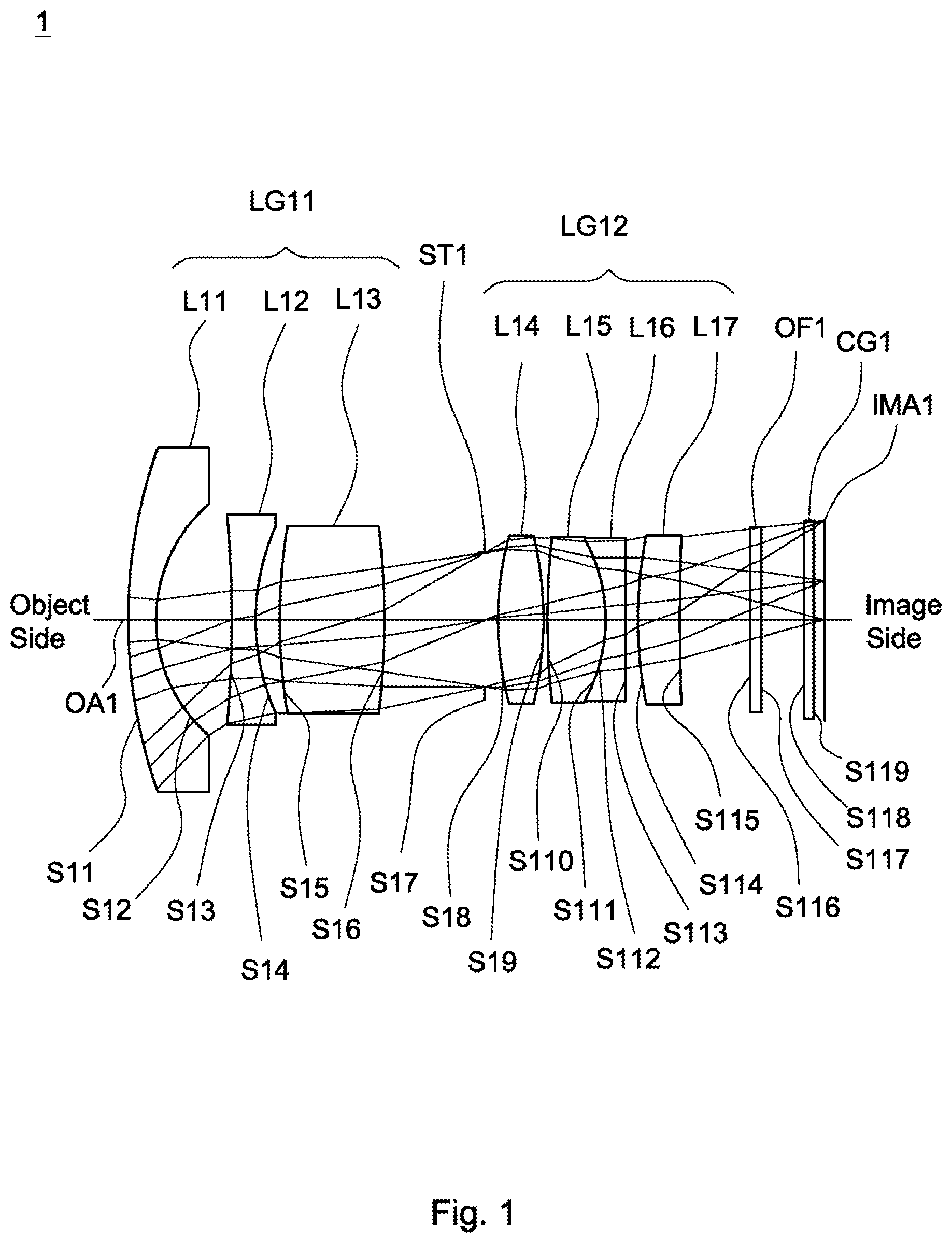
is a lens layout and optical path diagram of a lens assembly in accordance with a first embodiment of the invention;
A depicts a field curvature diagram of the lens assembly in accordance with the first embodiment of the invention;
B is a distortion diagram of the lens assembly in accordance with the first embodiment of the invention;
C is a spot diagram of the lens assembly in accordance with the first embodiment of the invention;
D is a through focus modulation transfer function diagram of the lens assembly in accordance with the first embodiment of the invention;
is a lens layout and optical path diagram of a lens assembly in accordance with a second embodiment of the invention;
A depicts a field curvature diagram of the lens assembly in accordance with the second embodiment of the invention;
B is a distortion diagram of the lens assembly in accordance with the second embodiment of the invention;
C is a spot diagram of the lens assembly in accordance with the second embodiment of the invention;
D is a through focus modulation transfer function diagram of the lens assembly in accordance with the second embodiment of the invention.
is a lens layout and optical path diagram of a lens assembly in accordance with a third embodiment of the invention;
A depicts a field curvature diagram of the lens assembly in accordance with the third embodiment of the invention;
B is a distortion diagram of the lens assembly in accordance with the third embodiment of the invention;
C is a spot diagram of the lens assembly in accordance with the third embodiment of the invention;
D is a through focus modulation transfer function diagram of the lens assembly in accordance with the third embodiment of the invention;
is a lens layout and optical path diagram of a lens assembly in accordance with a fourth embodiment of the invention;
A depicts a field curvature diagram of the lens assembly in accordance with the fourth embodiment of the invention;
B is a distortion diagram of the lens assembly in accordance with the fourth embodiment of the invention;
C is a spot diagram of the lens assembly in accordance with the fourth embodiment of the invention; and
D is a through focus modulation transfer function diagram of the lens assembly in accordance with the fourth embodiment of the invention.
DETAILED DESCRIPTION OF THE INVENTION
The following description is made for the purpose of illustrating the general principles of the invention and should not be taken in a limiting sense. The scope of the invention is best determined by reference to the appended claims.
The present invention provides a lens assembly including a first lens, a second lens, a third lens, a stop, a fourth lens, a fifth lens, a sixth lens, and a seventh lens. The first lens is a meniscus lens with refractive power, and includes a convex surface facing the object side and a concave surface facing the image side. The second lens is with negative refractive power. The third lens is with positive refractive power and includes a convex surface facing the image side. The fourth lens is with refractive power and includes a convex surface facing the image side. The fifth lens is with positive refractive power and includes a convex surface facing the object side. The sixth lens is a biconcave lens with negative refractive power, and includes a concave surface facing the object side and another concave surface facing the image side. The seventh lens is with refractive power and includes a convex surface facing the image side. The first lens, the second lens, the third lens, the stop, the fourth lens, the fifth lens, the sixth lens, and the seventh lens are arranged in order from the object side to the image side along an optical axis. The lens assembly satisfies: 4.3≤TTL/BFL≤5.3; wherein TTL is an interval in mm from an object side surface of the first lens to an image plane along the optical axis and BFL is an interval in mm from an image side surface of the seventh lens to the image plane along the optical axis.
The present invention provides another lens assembly including a first lens, a second lens, a third lens, a stop, a fourth lens, a fifth lens, a sixth lens, and a seventh lens. The first lens is a meniscus lens with refractive power, and includes a convex surface facing the object side and a concave surface facing the image side. The second lens is with negative refractive power and includes a concave surface facing the image side. The third lens is with positive refractive power and includes a convex surface facing the image side. The fourth lens is with refractive power and includes a convex surface facing the image side. The fifth lens is with positive refractive power and includes a convex surface facing the object side. The sixth lens is a biconcave lens with negative refractive power, and includes a concave surface facing the object side and another concave surface facing the image side. The seventh lens is with refractive power and includes a convex surface facing the image side. The first lens, the second lens, the third lens, the stop, the fourth lens, the fifth lens, the sixth lens, and the seventh lens are arranged in order from the object side to the image side along an optical axis. The lens assembly satisfies: −1≤(R 41 +R 42 )/(R 41 −R 42 )≤0; wherein R 41 is a radius of curvature of the object side surface of the fourth lens and R 42 is a radius of curvature of the image side surface of the fourth lens.
Referring to Table 1, Table 2, Table 4, Table 5, Table 7, Table 8, Table 10, and Table 11, wherein Table 1, Table 4, Table 7, and Table 10 show optical specification in accordance with a first, second, third and fourth embodiments of the invention respectively and Table 2, Table 5, Table 8, and Table 11 show aspheric coefficient of each aspheric lens in Table 1, Table 4, Table 7, and Table 10 respectively.
, , , and are lens layout and optical path diagrams of the lens assembly in accordance with the first, second, third, and fourth embodiments of the invention respectively. The first lens group LG 11 , LG 21 , LG 31 , LG 41 including a first lens L 11 , L 21 , L 31 , L 41 , a second lens L 12 , L 22 , L 32 , L 42 , and a third lens L 13 , L 23 , L 33 , L 43 . The second lens group LG 12 , LG 22 , LG 32 , LG 42 including a fourth lens L 14 , L 24 , L 34 , L 44 , a fifth lens L 15 , L 25 , L 35 , L 45 , a sixth lens L 16 , L 26 , L 36 , L 46 , and a seventh lens L 17 , L 27 , L 37 , L 47 .
The first lens L 11 , L 21 , L 31 , L 41 are meniscus lenses with negative refractive power and made of glass material, wherein the object side surfaces S 11 , S 21 , S 31 , S 41 are convex surfaces, the image side surfaces S 12 , S 22 , S 32 , S 42 are concave surfaces, and the object side surfaces S 11 , S 21 , S 31 , S 41 and the image side surfaces S 12 , S 22 , S 32 , S 42 are spherical surfaces.
The second lens L 12 , L 22 , L 32 , L 42 are with negative refractive power and made of glass material, wherein the image side surfaces S 14 , S 24 , S 34 , S 44 are concave surfaces.
The third lens L 13 , L 23 , L 33 , L 43 are with positive refractive power and made of glass material, wherein the image side surfaces S 16 S 26 , S 36 S 46 are convex surfaces, and the object side surfaces S 15 , S 25 , S 35 , S 45 and the image side surfaces S 16 , S 26 , S 36 , S 46 are spherical surfaces.
The fourth lens L 14 , L 24 , L 34 , L 44 are biconvex lenses with positive refractive power and made of glass material, wherein the object side surfaces S 18 , S 28 , S 38 , S 48 are convex surfaces, and the image side surfaces S 19 , S 29 , S 39 , S 49 are convex surface.
The fifth lens L 15 , L 25 , L 35 , L 45 are biconvex lenses with positive refractive power and made of glass material, wherein the object side surfaces S 110 , S 210 , S 310 , S 410 are convex surfaces, the image side surfaces S 111 , S 211 , S 311 , S 411 are convex surfaces, and the object side surfaces S 110 , S 210 , S 310 , S 410 and the image side surfaces S 111 , S 211 , S 311 , S 411 are spherical surfaces.
The sixth lens L 16 , L 26 , L 36 , L 46 are biconcave lenses with negative refractive power and made of glass material, wherein the object side surfaces S 112 , S 212 , S 312 , S 412 are concave surfaces, the image side surfaces S 113 , S 213 , S 313 , S 413 are concave surfaces, and the object side surfaces S 112 , S 212 , S 312 , S 412 and the image side surfaces S 113 , S 213 , S 313 , S 413 are spherical surfaces.
The seventh lens L 17 , L 27 , L 37 , L 47 are biconvex lenses with positive refractive power and made of glass material, wherein the object side surfaces S 114 , S 214 S 314 S 414 are convex surfaces, the image side surfaces S 115 , S 215 , S 315 , S 415 are convex surfaces, and the object side surfaces S 114 , S 214 , S 314 , S 414 and the image side surfaces S 115 , S 215 , S 315 , S 415 are aspheric surfaces.
The fifth lenses L 15 , L 25 , L 35 , L 45 and the sixth lenses L 16 , L 26 , L 36 , L 46 are cemented respectively.
In addition, the lens assembly 1 , 2 , 3 , 4 satisfy at least one of the following conditions: 4.3≤ TTL/BFL≤ 5.3; (1) −1≤( R 41 +R 42 )/( R 41 −R 42 )≤0; (2) 8.5≤ TTL/f≤ 11.5; (3) −3.5≤ f 1 /f≤− 2.4; (4) 3≤ f 3 /f≤ 6; (5) 2.5≤ f 7 /f≤ 5.2; (6) 17.4 mm≤ f+f 3 ≤23.8 mm; (7)
wherein TTL is an interval in mm from the object side surfaces S 11 , S 21 , S 31 , S 41 of the first lenses L 11 , L 21 , L 31 , L 41 to the image planes IMA 1 , IMA 2 , IMA 3 , IMA 4 along the optical axes OA 1 , OA 2 , OA 3 , OA 4 respectively for the first to fourth embodiments, BFL is an interval in mm from the image side surfaces S 115 , S 215 , S 315 . S 415 of the seventh lenses L 17 , L 27 , L 37 , L 47 to the image planes IMA 1 , IMA 2 , IMA 3 , IMA 4 along the optical axes OA 1 , OA 2 , OA 3 , OA 4 respectively for the first to fourth embodiments, R 41 is a radius of curvature of the object side surface S 18 , S 28 , S 38 , S 48 of the fourth lens L 14 , L 24 , L 34 , L 44 for the first to fourth embodiments, R 42 is a radius of curvature of the image side surface S 19 , S 29 , S 39 , S 49 of the fourth lens L 14 L 24 , L 34 L 44 for the first to fourth embodiments, f 1 is an effective focal length of the first lenses L 11 , L 21 , L 31 , L 41 for the first to fourth embodiments, f 3 is an effective focal length of the third lenses L 13 , L 23 , L 33 , L 43 for the first to fourth embodiments, f 7 is an effective focal length of the seventh lenses L 17 , L 27 , L 37 , L 47 for the first to fourth embodiments, and f is an effective focal length of the lens assemblies 1 , 2 , 3 , 4 for the first to fourth embodiments. With the lens assemblies 1 , 2 , 3 , 4 satisfying at least one of the above conditions (1)-(7), the field of view can be effectively increased, the resolution can be effectively increased, the environmental temperature change can be effectively resisted, the different focus while day and night can be effectively corrected, the aberration can be effectively corrected, and the chromatic aberration can be effectively corrected.
When the condition (1): 4.3≤TTL/BFL≤5.3 is satisfied, the back focal length can be increased, and helpful for assembling of the lens assembly.
When the condition (2): −1≤(R 41 ±R 42 )/(R 41 −R 42 )≤0 is satisfied, the outer shape of the fourth lens can be controlled effectively, and the back focal length can be increased.
When the condition (3): 8.5≤TTL/f≤11.5 is satisfied, the total length of the lens assembly can be decreased.
When the condition (4): −3.5≤f 1 /f≤−2.4 is satisfied, it can provide sufficient negative refractive power.
When the condition (5): 3≤f 3 /f≤6 is satisfied, the refractive power of the single lens in the lens assembly can be decreased, and to avoid the difference of the refractive power between lenses are too much to over image corrected or insufficient image corrected.
When the condition (6): 2.5≤f 7 /f≤5.2 is satisfied, it can provide sufficient positive refractive power.
When the condition (7): 17.4 mm≤f+f 3 ≤23.8 mm is satisfied, it can make the refractive power of the third lens not too high and help the processing of the third lens.
The common effect of condition (1): 4.3≤TTL/BFL≤5.3 and condition (2): −1≤(R 41 +R 42 )/(R 41 −R 42 )≤0 is to achieve a longer back focal length, which allows greater flexibility in the design of the mechanism and facilitates assembling lens assembly.
When the first lens is a meniscus lens, it can achieve the function of large field of view with large light collection. When the second lens is a meniscus lens, it can further assist the shortage of light collection of the first lens. The third lens and the fourth lens both with positive refractive power, which can balance the first lens and the second lens both with negative refractive power, in order to correct the aberration. The fifth lens and the sixth lens are cemented together to effectively eliminate axial chromatic aberration and lateral chromatic aberration to enhance the resolution of the lens assembly. The seventh lens uses an aspheric design to correct the angle of incidence of light, which can significantly correct the field curvature and distortion of the lens assembly. When the stop is dispose between the third lens and the fourth lens, it can balance various types of aberration, reduce the outer diameter of the first lens and the seventh lens and to decrease the outer diameter of the imaging lens.
A detailed description of a lens assembly in accordance with a first embodiment of the invention is as follows. Referring to , the lens assembly 1 includes a first lens group LG 11 , a stop ST 1 , a second lens group LG 12 , an optical filter OF 1 , and a cover glass CG 1 . The first lens group LG 11 includes a first lens L 11 , a second lens L 12 and a third lens L 13 in order from an object side to an image side along an optical axis OA 1 . The second lens group LG 12 includes a fourth lens L 14 , a fifth lens L 15 , a sixth lens L 16 and a seventh lens L 17 in order from the object side to the image side along the optical axis OA 1 . In operation, an image of light rays from the object side is formed at an image plane IMA 1 .
According to the foregoing, wherein: the second lens L 12 is a biconcave lens, wherein the object side surface S 13 is a concave surface, and both of the object side surface S 13 and the image side surface S 14 are spherical surface; the third lens L 13 is a biconvex lens, wherein the object side surface S 15 is a convex surface; both of the object side surface S 18 and the image side surface S 19 of the fourth lens L 14 are aspheric surfaces; both of the object side surface S 116 and image side surface S 117 of the optical filter OF 1 are plane surfaces; and both of the object side surface S 118 and image side surface S 119 of the cover glass CG 1 are plane surfaces.
With the above design of the lenses and stop ST 1 and at least any one of the conditions (1)-(7) satisfied, the lens assembly 1 can have an effective increased field of view, an effective increased resolution, an effective resisted environmental temperature change, the different focus while day and night can be effectively corrected, an effective corrected aberration, and is capable of an effective corrected chromatic aberration.
Table 1 shows the optical specification of the lens assembly 1 in .
TABLE 1
Effective Focal Length = 3.65 mm F-number = 2.20
Total Lens Length = 32.00 mm Field of View = 111.09 degrees
Effective
Radius of Thick- Focal
Surface Curvature ness Length
Number (mm) (mm) Nd Vd (mm) Remark
S11 15.50 1.25 1.8 46.6 −9.62 The First
Lens L11
S12 4.99 3.47
S13 −33.82 1.09 1.75 45.4 −7.32 The Second
Lens L12
S14 6.74 1.09
S15 17.19 4.81 1.76 27.5 13.83 The Third
Lens L13
S16 −23.88 4.68
S17 ∞ 0.56 Stop ST1
S18 8.03 2.04 1.77 49.6 7.38 The Fourth
Lens L14
S19 −17.60 0.31
S110 35.58 2.62 1.5 81.5 8.55 The Fifth
Lens L15
S111 −4.72 0.00
S112 −4.72 0.90 1.81 25.5 −5.68 The Sixth
Lens L16
S113 200.93 0.61
S114 12.30 1.88 1.67 55.4 18.26 The Seventh
Lens L17
S115 −1439.16 3.27
S116 ∞ 0.50 1.52 64.2 Optical
Filter OF1
S117 ∞ 2.00
S118 ∞ 0.40 1.52 64.2 Cover Glass
CG1
S119 ∞ 0.52
The aspheric surface sag z of each aspheric lens in table 1 can be calculated by the following formula: z=ch 2 /{1+[1−( k+ 1) c 2 h 2 ] 1/2 }+Ah 4 +Bh 6 +Ch 8 +Dh 10 +Eh 12 +Fh 14 where c is curvature, h is the vertical distance from the lens surface to the optical axis, k is conic constant and A, B, C, D, E, and F are aspheric coefficients.
In the first embodiment, the conic constant k and the aspheric coefficients A, B, C, D, E, F of each aspheric surface are shown in Table 2.
TABLE 2
Surface A B
Number k E F C D
S18 0.063 −3.1940E−04 −3.4575E−05 −2.7049E−07 −1.8221E−07
−2.5748E−08 0
S19 15.286 −1.4949E−04 −3.8689E−05 2.3719E−06 −6.0220E−07
8.1311E−09 0
S114 0.875 −4.2828E−04 −3.3596E−05 3.5171E−06 −8.9435E−07
5.4330E−08 0
S115 84482.227 1.2704E−03 −8.5531E−06 2.5792E−06 −6.2834E−07
4.2507E−08 0
Table 3 shows the parameters and condition values for conditions (1)-(7) in accordance with the first embodiment of the invention. It can be seen from Table 3 that the lens assembly 1 of the first embodiment satisfies the conditions (1)-(7).
TABLE 3
BFL 6.70 mm
TTL/BFL 4.78 (R 41 + R 42 )/(R 41 − R 42 ) −0.37 TTL/f 8.77
f 1 /f −2.64 f 3 /f 3.79 f 7 /f 5.00
f + f 3 17.480
By the above arrangements of the lenses and stop ST 1 , the lens assembly 1 of the first embodiment can meet the requirements of optical performance. It can be seen from A that the field curvature of tangential direction and sagittal direction in the lens assembly 1 of the first embodiment ranges from −0.04 mm to 0.10 mm. It can be seen from B that the distortion in the lens assembly 1 of the first embodiment ranges from −35% to 0%. It can be seen from C that the root mean square spot radius is equal to 2.095 μm and geometrical spot radius is equal to 7.171 μm as image height is equal to 0.000 mm, the root mean square spot radius is equal to 2.774 μm and geometrical spot radius is equal to 13.436 μm as image height is equal to 1.087 mm, the root mean square spot radius is equal to 3.505 μm and geometrical spot radius is equal to 16.808 μm as image height is equal to 1.811 mm, the root mean square spot radius is equal to 4.586 μm and geometrical spot radius is equal to 21.158 μm as image height is equal to 2.898 mm, and the root mean square spot radius is equal to 5.873 μm and geometrical spot radius is equal to 27.068 μm as image height is equal to 3.623 mm for the lens assembly 1 of the first embodiment. It can be seen from D that the through focus modulation transfer function of tangential direction and sagittal direction in the lens assembly 1 of the first embodiment ranges from 0.0 to 0.76 as focus shift ranges from −0.05 mm to 0.05 mm. It is obvious that the field curvature and the distortion of the lens assembly 1 of the first embodiment can be corrected effectively, and the depth of focus of the lens assembly 1 of the first embodiment can meet the requirement. Therefore, the lens assembly 1 of the first embodiment is capable of good optical performance.
Referring to , is a lens layout and optical path diagram of a lens assembly in accordance with a second embodiment of the invention. The lens assembly 2 includes a first lens group LG 21 , a stop ST 2 , a second lens group LG 22 , an optical filter OF 2 , and a cover glass CG 2 . The first lens group LG 21 includes a first lens L 21 , a second lens L 22 and a third lens L 23 in order from an object side to an image side along an optical axis OA 2 . The second lens group LG 22 includes a fourth lens L 24 , a fifth lens L 25 , a sixth lens L 26 and a seventh lens L 27 in order from the object side to the image side along the optical axis OA 2 . In operation, an image of light rays from the object side is formed at an image plane IMA 2 .
According to the foregoing, wherein: the second lens L 22 is a meniscus lens, wherein the object side surface S 23 is a convex surface, and both of the object side surface S 23 and the image side surface S 24 are aspheric surface; the third lens L 23 is a meniscus lens, wherein the object side surface S 25 is a concave surface; both of the object side surface S 28 and the image side surface S 29 of the fourth lens L 24 are spherical surfaces; both of the object side surface S 216 and image side surface S 217 of the optical filter OF 2 are plane surfaces; and both of the object side surface S 218 and image side surface S 219 of the cover glass CG 2 are plane surfaces.
With the above design of the lenses and stop ST 2 and at least any one of the conditions (1)-(7) satisfied, the lens assembly 2 can have an effective increased field of view, an effective increased resolution, an effective resisted environmental temperature change, the different focus while day and night can be effectively corrected, an effective corrected aberration, and is capable of an effective corrected chromatic aberration.
Table 4 shows the optical specification of the lens assembly 2 in .
TABLE 4
Effective Focal Length = 3.61 mm F-number = 2.00
Total Lens Length = 38.04 mm Field of View = 111.08 degrees
Radius of Thick- Effective
Surface Curvature ness Focal Length
Number (mm) (mm) Nd Vd (mm) Remark
S21 28.56 1.21 1.8 46.6 −11.82 The First
Lens L21
S22 7.02 2.25
S23 7.41 0.84 1.75 45.4 −12.04 The Second
Lens L22
S24 3.89 6.22
S25 −134.72 3.75 1.76 27.5 19.4 The Third
Lens L23
S26 −13.47 7.49
S27 ∞ 0.09 Stop ST2
S28 14.32 1.74 1.77 49.6 11.13 The Fourth
Lens L24
S29 −20.58 0.23
S210 29.67 2.53 1.5 81.5 12.03 The Fifth
Lens L25
S211 −7.30 0.00
S212 −7.30 0.92 1.81 25.5 −6.1 The Sixth
Lens L26
S213 16.28 0.30
S214 15.37 2.47 1.67 55.4 10.65 The
Seventh
Lens L27
S215 −12.40 4.44
S216 ∞ 0.70 1.52 64.2 Optical
Filter OF2
S217 ∞ 2.00
S218 ∞ 0.40 1.52 64.2 Cover Glass
CG2
S219 ∞ 0.48
The definition of aspheric surface sag z of each aspheric lens in table 4 is the same as that of in Table 1, and is not described here again.
In the second embodiment, the conic constant k and the aspheric coefficients A, B, C, D, E, F of each aspheric surface are shown in Table 5.
TABLE 5
Surface A B
Number k E F C D
S23 −0.591 −4.2471E−04 −2.7645E−05 1.0776E−06 −2.9308E−08
3.7293E−10 0
S24 −1.035 5.6206E−04 −5.5274E−05 2.3166E−06 −1.0623E−07
2.1644E−09 0
S214 6.717 −2.0352E−04 1.3335E−05 5.8164E−07 2.6889E−08
−9.7213E−10 0
S215 1.208 5.4512E−04 1.2665E−05 3.3181E−07 8.0310E−08
−1.1636E−09 0
Table 6 shows the parameters and condition values for conditions (1)-(7) in accordance with the second embodiment of the invention. It can be seen from Table 6 that the lens assembly 2 of the second embodiment satisfies the conditions (1)-(7).
TABLE 6
BFL 8.02 mm
TTL/BFL 4.74 (R 41 + R 42 )/(R 41 − R 42 ) −0.18 TTL/f 10.54
f 1 /f −3.27 f 3 /f 5.37 f 7 /f 2.95
f + f 3 23.010
By the above arrangements of the lenses and stop ST 2 , the lens assembly 2 of the second embodiment can meet the requirements of optical performance. It can be seen from A that the field curvature of tangential direction and sagittal direction in the lens assembly 2 of the second embodiment ranges from −0.04 mm to 0.09 mm. It can be seen from B that the distortion in the lens assembly 2 of the second embodiment ranges from −35% to 0%. It can be seen from C that the root mean square spot radius is equal to 2.231 μm and geometrical spot radius is equal to 10.261 μm as image height is equal to 0.000 mm, the root mean square spot radius is equal to 2.836 μm and geometrical spot radius is equal to 13.447 μm as image height is equal to 1.087 mm, the root mean square spot radius is equal to 3.392 μm and geometrical spot radius is equal to 15.453 μm as image height is equal to 1.811 mm, the root mean square spot radius is equal to 4.445 μm and geometrical spot radius is equal to 19.343 μm as image height is equal to 2.898 mm, and the root mean square spot radius is equal to 5.316 μm and geometrical spot radius is equal to 22.795 μm as image height is equal to 3.623 rum for the lens assembly 2 of the second embodiment. It can be seen from D that the through focus modulation transfer function of tangential direction and sagittal direction in the lens assembly 2 of the second embodiment ranges from 0.0 to 0.75 as focus shift ranges from −0.05 mm to 0.05 mm. It is obvious that the field curvature and the distortion of the lens assembly 2 of the second embodiment can be corrected effectively, and the depth of focus of the lens assembly 2 of the second embodiment can meet the requirement. Therefore, the lens assembly 2 of the second embodiment is capable of good optical performance.
Referring to , is a lens layout and optical path diagram of a lens assembly in accordance with a third embodiment of the invention. The lens assembly 3 includes a first lens group LG 31 , a stop ST 3 , a second lens group LG 32 , an optical filter OF 3 , and a cover glass CG 3 . The first lens group LG 31 includes a first lens L 31 , a second lens L 32 and a third lens L 33 in order from an object side to an image side along an optical axis OA 3 . The second lens group LG 32 includes a fourth lens L 34 , a fifth lens L 35 , a sixth lens L 36 and a seventh lens L 37 in order from the object side to the image side along the optical axis OA 3 . In operation, an image of light rays from the object side is formed at an image plane IMA 3 .
According to the foregoing, wherein: the second lens L 32 is a meniscus lens, wherein the object side surface S 33 is a convex surface, and both of the object side surface S 33 and the image side surface S 34 are aspheric surface; the third lens L 33 is a meniscus lens, wherein the object side surface S 35 is a concave surface; both of the object side surface S 38 and the image side surface S 39 of the fourth lens L 34 are spherical surfaces; both of the object side surface S 316 and image side surface S 317 of the optical filter OF 3 are plane surfaces; and both of the object side surface S 318 and image side surface S 319 of the cover glass CG 3 are plane surfaces.
With the above design of the lenses and stop ST 3 and at least any one of the conditions (1)-(7) satisfied, the lens assembly 3 can have an effective increased field of view, an effective increased resolution, an effective resisted environmental temperature change, the different focus while day and night can be effectively corrected, an effective corrected aberration, and is capable of an effective corrected chromatic aberration.
Table 7 shows the optical specification of the lens assembly 3 in .
TABLE 7
Effective Focal Length = 3.59 mm F-number = 2.05
Total Lens Length = 38.81 mm Field of View = 110.59 degrees
Radius of Thick- Effective
Surface Curvature ness Focal Length
Number (mm) (mm) Nd Vd (mm) Remark
S31 36.03 1.30 1.8 46.6 −11.81 The First
Lens L31
S32 7.42 2.22
S33 9.76 1.16 1.75 45.3 −13.23 The Second
Lens L32
S34 4.68 7.10
S35 −113.37 3.91 1.76 27.5 19.89 The Third
Lens L33
S36 −13.55 7.14
S37 ∞ 0.18 Stop ST3
S38 10.38 1.95 1.69 54.6 12.75 The Fourth
Lens L34
S39 −55.94 0.25
S310 14.51 2.20 1.5 81.5 13.39 The Fifth
Lens L35
S311 −11.72 0.00
S312 −11.72 0.83 1.81 25.5 −6.07 The Sixth
Lens L36
S313 8.77 0.45
S314 12.49 2.10 1.67 55.1 9.29 The
Seventh
Lens L37
S315 −11.51 4.44
S316 ∞ 0.70 1.52 64.2 Optical
Filter OF3
S317 ∞ 2.00
S318 ∞ 0.40 1.52 64.2 Cover Glass
CG3
S319 ∞ 0.47
The definition of aspheric surface sag z of each aspheric lens in table 7 is the same as that of in Table 1, and is not described here again.
In the third embodiment, the conic constant k and the aspheric coefficients A, B, C, D, E, F of each aspheric surface are shown in Table 8.
TABLE 8
Surface A B
Number k E F C D
S33 1.0793 0.00055681 −5.38E−05 1.18072E−06 −2.558E−08
2.4042E−10 0
S34 −0.5729 0.00118637 −7.492E−05 1.09791E−06 −5.986E−08
1.4542E−09 0
S314 1.3061 −3.210E−04 −1.974E−05 4.887E−06 −4.004E−07
1.103E−08 8.847E−11
S315 0.5403 3.598E−04 −8.235E−06 −3.336E−07 3.277E−07
−3.189E−08 9.927E−10
Table 9 shows the parameters and condition values for conditions (1)-(7) in accordance with the third embodiment of the invention. It can be seen from Table 9 that the lens assembly 3 of the third embodiment satisfies the conditions (1)-(7).
TABLE 9
BFL 8.02 mm
TTL/BFL 4.84 (R 41 + R 42 )/(R 41 − R 42 ) −0.69 TTL/f 10.81
f 1 /f −3.29 f 3 /f 5.54 f 7 /f 2.59
f + f 3 23.480
By the above arrangements of the lenses and stop ST 3 , the lens assembly 3 of the third embodiment can meet the requirements of optical performance. It can be seen from A that the field curvature of tangential direction and sagittal direction in the lens assembly 3 of the third embodiment ranges from −0.04 mm to 0.05 mm. It can be seen from B that the distortion in the lens assembly 3 of the third embodiment ranges from −30% to 0%. It can be seen from C that the root mean square spot radius is equal to 1.732 μm and geometrical spot radius is equal to 6.538 μm as image height is equal to 0.000 mm, the root mean square spot radius is equal to 2.215 μm and geometrical spot radius is equal to 11.996 μm as image height is equal to 1.087 mm, the root mean square spot radius is equal to 2.626 μm and geometrical spot radius is equal to 14.127 μm as image height is equal to 1.811 mm, the root mean square spot radius is equal to 3.726 μm and geometrical spot radius is equal to 19.580 μm as image height is equal to 2.898 mm, and the root mean square spot radius is equal to 4.956 μm and geometrical spot radius is equal to 20.056 μm as image height is equal to 3.623 mm for the lens assembly 3 of the third embodiment. It can be seen from D that the through focus modulation transfer function of tangential direction and sagittal direction in the lens assembly 3 of the third embodiment ranges from 0.0 to 0.75 as focus shift ranges from −0.05 mm to 0.05 mm. It is obvious that the field curvature and the distortion of the lens assembly 3 of the third embodiment can be corrected effectively, and the depth of focus of the lens assembly 3 of the third embodiment can meet the requirement. Therefore, the lens assembly 3 of the third embodiment is capable of good optical performance.
Referring to , is a lens layout and optical path diagram of a lens assembly in accordance with a fourth embodiment of the invention. The lens assembly 4 includes a first lens group LG 41 , a stop ST 4 , a second lens group LG 42 , an optical filter OF 4 , and a cover glass CG 4 . The first lens group LG 41 includes a first lens L 41 , a second lens L 42 and a third lens L 43 in order from an object side to an image side along an optical axis OA 4 . The second lens group LG 42 includes a fourth lens L 44 , a fifth lens L 45 , a sixth lens L 46 and a seventh lens L 47 in order from the object side to the image side along the optical axis OA 4 . In operation, an image of light rays from the object side is formed at an image plane IMA 4 .
According to the foregoing, wherein: the second lens L 42 is a meniscus lens, wherein the object side surface S 43 is a convex surface, and both of the object side surface S 43 and the image side surface S 44 are aspheric surface; the third lens L 43 is a plane-convex lens, wherein the object side surface S 45 is a plane surface; both of the object side surface S 48 and the image side surface S 49 of the fourth lens L 44 are spherical surfaces; both of the object side surface S 416 and image side surface S 417 of the optical filter OF 4 are plane surfaces; and both of the object side surface S 418 and image side surface S 419 of the cover glass CG 4 are plane surfaces.
With the above design of the lenses and stop ST 4 and at least any one of the conditions (1)-(7) satisfied, the lens assembly 4 can have an effective increased field of view, an effective increased resolution, an effective resisted environmental temperature change, the different focus while day and night can be effectively corrected, an effective corrected aberration, and is capable of an effective corrected chromatic aberration.
Table 10 shows the optical specification of the lens assembly 4 in .
TABLE 10
Effective Focal Length = 3.62 mm F-number = 1.95
Total Lens Length = 39.50 mm Field of View = 110.63 degrees
Radius of Thick- Effective
Surface Curvature ness Focal Length
Number (mm) (mm) Nd Vd (mm) Remark
S41 25.05 1.30 1.8 46.6 −10.59 The First
Lens L41
S42 6.23 2.67
S43 16.41 1.43 1.74 49.2 −14.56 The Second
Lens L42
S44 6.27 4.74
S45 ∞ 6.39 1.76 27.5 20.04 The Third
Lens L43
S46 −15.25 6.56
S47 ∞ 0.31 Stop ST4
S48 22.10 1.81 1.69 54.6 16.18 The Fourth
Lens L44
S49 −22.10 0.16
S410 8.53 2.49 1.5 81.5 12.08 The Fifth
Lens L45
S411 −18.44 0.00
S412 −18.44 1.00 1.81 25.5 −6.59 The Sixth
Lens L46
S413 7.72 0.45
S414 10.96 2.18 1.68 54.9 9.73 The
Seventh
Lens L47
S415 −15.14 3.44
S416 ∞ 0.70 1.52 64.2 Optical
Filter OF4
S417 ∞ 3.00
S418 ∞ 0.40 1.52 64.2 Cover Glass
CG4
S419 ∞ 0.48
The definition of aspheric surface sag z of each aspheric lens in table 10 is the same as that of in Table 1, and is not described here again.
In the fourth embodiment, the conic constant k and the aspheric coefficients A, B, C, D, E, F of each aspheric surface are shown in Table 11.
TABLE 11
Surface A B
Number k E F C D
S43 3.6941 0.00078745 −3.744E−05 7.90963E−07 −1.621E−08
1.8569E−10 −8.5911E−13
S44 −0.1098 0.00115783 −4.995E−05 8.02588E−07 −6.08E−08
1.8617E−09 −2.2424E−11
S414 3.2631 −4.486E−04 2.714E−06 −1.626E−06 1.616E−07
−1.035E−08 1.974E−10
S415 −0.4659 1.268E−04 2.027E−06 −8.169E−07 5.634E−08
−5.744E−10 −1.158E−10
Table 12 shows the parameters and condition values for conditions (1)-(7) in accordance with the fourth embodiment of the invention. It can be seen from Table 12 that the lens assembly 4 of the fourth embodiment satisfies the conditions (1)-(7).
TABLE 12
BFL 8.02 mm
TTL/BFL 4.93 (R 41 + R 42 )/(R 41 − R 42 ) 0 TTL/f 10.93
f 1 /f −2.93 f 3 /f 5.54 f 7 /f 2.69
f + f 3 23.655
By the above arrangements of the lenses and stop ST 4 the lens assembly 4 of the fourth embodiment can meet the requirements of optical performance. It can be seen from A that the field curvature of tangential direction and sagittal direction in the lens assembly 4 of the fourth embodiment ranges from −0.04 mm to 0.08 mm. It can be seen from B that the distortion in the lens assembly 4 of the fourth embodiment ranges from −35% to 0%. It can be seen from C that the root mean square spot radius is equal to 2.065 μm and geometrical spot radius is equal to 8.410 μm as image height is equal to 0.000 mm, the root mean square spot radius is equal to 2.519 μm and geometrical spot radius is equal to 13.042 μm as image height is equal to 1.087 mm, the root mean square spot radius is equal to 2.992 μm and geometrical spot radius is equal to 15.527 μm as image height is equal to 1.811 mm, the root mean square spot radius is equal to 3.693 μm and geometrical spot radius is equal to 17.253 μm as image height is equal to 2.898 mm, and the root mean square spot radius is equal to 4.740 μm and geometrical spot radius is equal to 19.875 μm as image height is equal to 3.623 mm for the lens assembly 4 of the fourth embodiment. It can be seen from D that the through focus modulation transfer function of tangential direction and sagittal direction in the lens assembly 4 of the fourth embodiment ranges from 0.0 to 0.76 as focus shift ranges from −0.05 mm to 0.05 mm. It is obvious that the field curvature and the distortion of the lens assembly 4 of the fourth embodiment can be corrected effectively, and the depth of focus of the lens assembly 4 of the fourth embodiment can meet the requirement. Therefore, the lens assembly 4 of the fourth embodiment is capable of good optical performance.
While the invention has been described by way of example and in terms of the preferred embodiment(s), it is to be understood that the invention is not limited thereto. On the contrary, it is intended to cover various modifications and similar arrangements and procedures, and the scope of the appended claims therefore should be accorded the broadest interpretation so as to encompass all such modifications and similar arrangements and procedures.
Figures (20)
Citations
This patent cites (10)
- US6833964
- US11841549
- US2019/0187442
- US2021/0011258
- US2021/0096328
- US109445077
- US109960020
- US110133828
- US2003015035
- US2014102291