Lens Driving Device and Camera Module
Abstract
A lens driving device includes: a fixed member; a lens-retaining member; a guide mechanism; a piezoelectric driving portion; and a pressing member. The lens-retaining member, the guide mechanism, the piezoelectric driving portion, and the pressing member are each configured as described in the specification. The pressing member is formed of a leaf spring member. The pressing member includes: a fixed portion to be fixed to the fixed member; a support portion configured to support the piezoelectric driving portion; and an elastically deformable portion that is provided between the fixed portion and the support portion and is elastically deformable. The support portion includes a plate-shaped base portion that is continuous with the elastically deformable portion, and a folded portion that is folded from the base portion in an L shape and projects toward the lens-retaining member. The piezoelectric driving portion is fixed to the folded portion.
Claims (12)
1. A lens driving device, comprising: a fixed member; a lens-retaining member configured to retain a lens body; a guide mechanism configured to guide the lens-retaining member so as to be movable relative to the fixed member in an optical-axis direction; a piezoelectric driving portion that includes a piezoelectric element extending in a direction crossing the optical-axis direction, and is configured to move the lens-retaining member in the optical-axis direction; and a pressing member configured to press the piezoelectric driving portion against the lens-retaining member, the pressing member being formed of a leaf spring member, and including a fixed portion to be fixed to the fixed member, a support portion configured to support the piezoelectric driving portion, and an elastically deformable portion that is provided between the fixed portion and the support portion and is elastically deformable, the support portion including a plate-shaped base portion that is continuous with the elastically deformable portion, and a folded portion that is folded from the plate-shaped base portion in an L shape and projects toward the lens-retaining member, and the piezoelectric driving portion being fixed to the folded portion.
Show 11 dependent claims
2. The lens driving device according to claim 1 , wherein: the folded portion includes a recessed portion in a tip end thereof; the recessed portion includes an inner-edge portion, a first edge portion, and a second edge portion, the first edge portion and the second edge portion facing each other via the inner-edge portion; and the piezoelectric driving portion is fixed to the folded portion, with a part of the piezoelectric driving portion being located in the recessed portion, being disposed between the first edge portion and the second edge portion, and being in contact with the inner-edge portion of the recessed portion.
3. The lens driving device according to claim 1 , wherein positions at which the folded portion and the piezoelectric driving portion contact each other correspond to positions of nodes of the piezoelectric driving portion that vibrates so as to have two nodes.
4. The lens driving device according to claim 1 , wherein: a position at which the folded portion and the piezoelectric driving portion contact each other corresponds to a position at a predetermined distance from an end portion of the piezoelectric driving portion; and the predetermined distance is a distance of approximately one quarter a total length of the piezoelectric driving portion.
5. The lens driving device according to claim 1 , wherein: the piezoelectric driving portion and the folded portion are fixed with an adhesive; and the adhesive is adhered between one surface of the folded portion and the piezoelectric driving portion, and between another surface of the folded portion and the piezoelectric driving portion.
6. The lens driving device according to claim 1 , wherein: the fixed portion includes two fixed portions, the support portion includes two support portions, and the elastically deformable portion includes two elastically deformable portions; the two elastically deformable portions extend from corresponding base portions in directions away from each other, the corresponding base portions being the plate-shaped base portion; and an extending direction of the elastically deformable portion is along an extending direction of the piezoelectric element.
7. The lens driving device according to claim 6 , wherein: the two fixed portions are provided as extensions of the two elastically deformable portions; and the fixed portions are held by holding portions formed in the fixed member.
8. The lens driving device according to claim 6 , wherein each of the corresponding base portions has an opening.
9. The lens driving device according to claim 5 , wherein the pressing member includes an upper connecting portion and a lower connecting portion that connect two base portions, the two base portions being the plate-shaped base portion.
10. The lens driving device according to claim 1 , wherein: the lens-retaining member includes a receiving member formed of metal; the piezoelectric driving portion includes a contact member formed of metal; and the receiving member and the contact member are configured to contact each other.
11. The lens driving device according to claim 1 , wherein: the guide mechanism includes two guide portions that are disposed so as to face each other via the piezoelectric driving portion; each of the two guide portions includes a first groove provided in the lens-retaining member, a second groove provided in the fixed member and facing the first groove, and a ball disposed between the first groove and the second groove; and the first groove, the second groove, or both extend in the optical-axis direction.
12. A camera module, comprising: the lens driving device according to claim 1 ; the lens body; and an image-capturing element facing the lens body.
Full Description
Show full text →
CROSS-REFERENCE TO RELATED APPLICATION
This application is a continuation application of International Application No. PCT/JP2022/002338 filed on Jan. 24, 2022, and designated the U.S., which is based upon and claims priority to Japanese Patent Application No. 2021-010631, filed on Jan. 26, 2021, the entire contents of which are incorporated herein by reference.
BACKGROUND
1. Field of the Invention
The present disclosure relates to a lens driving device mounted in, for example, portable devices with cameras.
2. Description of the Related Art
Some lens driving units (lens driving devices) are able to move a lens carrier (lens-retaining member) relative to a module base (base member) in an optical-axis direction through frictional driving utilizing a bending motion of a piezoelectric element (see, for example, Patent Document 1). In these devices, a coil spring is utilized for pressing the piezoelectric element against the lens-retaining member.
CITATION LIST
Patent Document
• Patent Document 1: Japanese Laid-Open Patent Publication No. 2010-097216
In the above-described configuration, however, a plurality of coil springs is disposed, resulting in a complicated structure.
In view thereof, it is desirable to provide a lens driving device that is able to press a piezoelectric element against a lens-retaining member using a simpler structure.
SUMMARY
A lens driving device according to embodiments of the present invention includes: a fixed member; a lens-retaining member; a guide mechanism; a piezoelectric driving portion; and a pressing member. The lens-retaining member is configured to retain a lens body. The guide mechanism is configured to guide the lens-retaining member so as to be movable relative to the fixed member in an optical-axis direction. The piezoelectric driving portion includes a piezoelectric element extending in a direction crossing the optical-axis direction, and is configured to move the lens-retaining member in the optical-axis direction. The pressing member is configured to press the piezoelectric driving portion against the lens-retaining member. The pressing member is formed of a leaf spring member. The pressing member includes: a fixed portion to be fixed to the fixed member; a support portion configured to support the piezoelectric driving portion; and an elastically deformable portion that is provided between the fixed portion and the support portion and is elastically deformable. The support portion includes: a plate-shaped base portion that is continuous with the elastically deformable portion; and a folded portion that is folded from the base portion in an L shape and projects toward the lens-retaining member. The piezoelectric driving portion is fixed to the folded portion.
BRIEF DESCRIPTION OF DRAWINGS
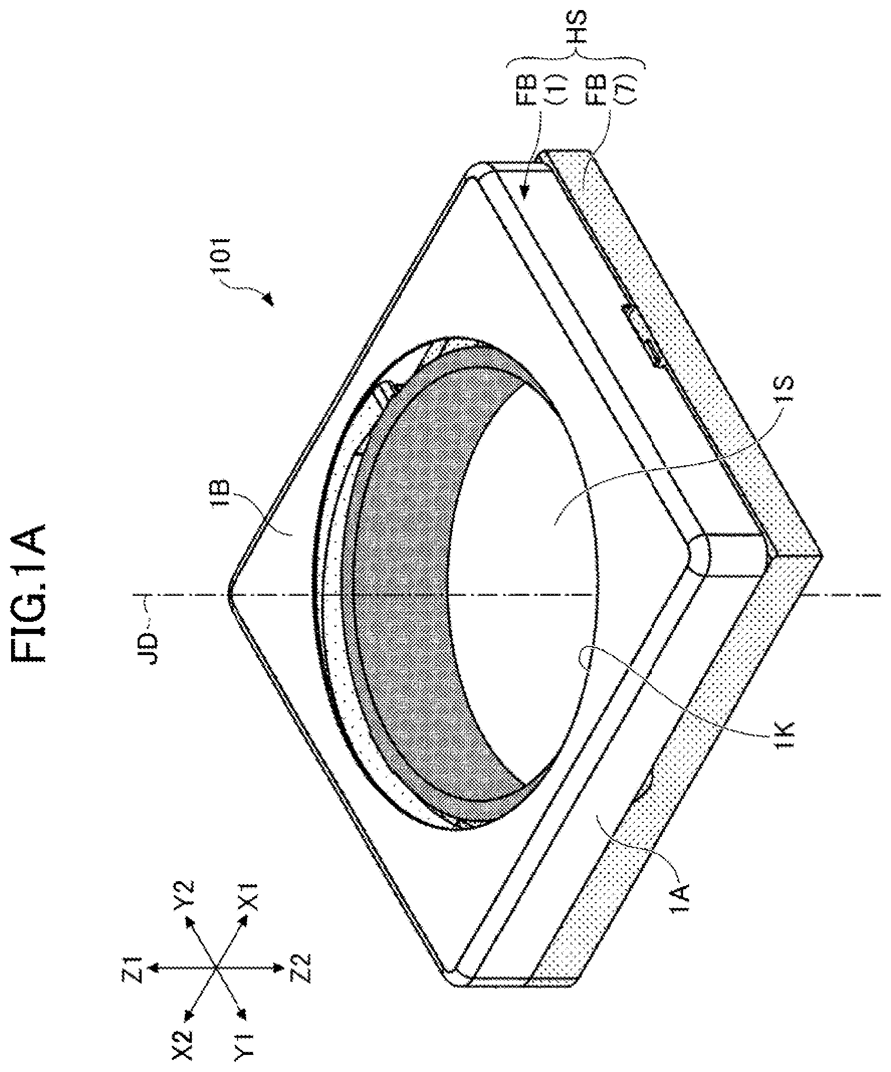
A is a perspective view of a lens driving device.
B is a perspective view of the lens driving device, with a cover member being removed.
is an exploded perspective view of the lens driving device.
A is a top view of a base member, with a link mechanism being attached.
B is a left-hand side view of the base member, with the link mechanism being attached.
C is a perspective view of the base member, with only a second link member being attached.
A is a perspective view of a lens-retaining member, with the link mechanism being attached.
B is a left-hand side view of the lens-retaining member, with the link mechanism being attached.
C is a left-hand side view of the lens-retaining member, with the link mechanism being attached.
A is a front view of the lens-retaining member, with the link mechanism being attached.
B is a front view of the lens-retaining member, with the link mechanism being attached.
A is a perspective view of the lens driving device, with the cover member being removed.
B is a perspective view of the lens driving device, with the cover member being removed.
A is a perspective view of the base member.
B is a perspective view of the base member, with balls being attached.
A is a perspective view of the entirety of the base member, with the lens-retaining member and the balls being attached.
B is a perspective view of a part of the base member.
A is a perspective view of the entirety of the lens-retaining member attached to the base member.
B is a perspective view of a part of the lens-retaining member.
A is a perspective view of the lens-retaining member.
B is a perspective view of the lens-retaining member to which the balls are attached.
A is a perspective view of the lens driving device, with the cover member being removed.
B is a perspective view of a part of the lens driving device, with the cover member being removed.
A is a perspective view of the entirety of a piezoelectric driving portion.
B is an exploded perspective view of the piezoelectric driving portion.
A is a perspective view of a pressing member.
B is a front view of the pressing member.
C is a top view of the pressing member.
D is a left-hand side view of the pressing member.
A is a perspective view of the pressing member to which the piezoelectric driving portion is attached.
B is a front view of the pressing member to which the piezoelectric driving portion is attached.
C is a top view of the pressing member to which the piezoelectric driving portion is attached.
D is a left-hand side view of the pressing member to which the piezoelectric driving portion is attached.
A is a front view of a part of the pressing member to which the piezoelectric driving portion is attached.
B is a left-hand side view of the pressing member to which the piezoelectric driving portion is attached.
A is a perspective view of the entirety of the base member to which the pressing member is attached.
B is a perspective view of a part of the base member to which the pressing member is attached.
A is a perspective view of another configuration example of the lens driving device, with the cover member being removed.
B is a perspective view of the other configuration example of the lens driving device, with some members being further removed.
A is a perspective view of another configuration example of the pressing member.
B is a front view of the other configuration example of the pressing member.
C is a top view of the other configuration example of the pressing member.
D is a left-hand side view of the other configuration example of the pressing member.
EMBODIMENTS
Hereinafter, a lens driving device 101 according to the embodiments of the present invention will be described with reference to the drawings. A and B are perspective views of the lens driving device 101 . Specifically, A is a perspective view of the entirety of the lens driving device 101 , and B is a perspective view of the lens driving device 101 , with a cover member 1 being removed. is an exploded perspective view of the lens driving device 101 .
In A and B , X 1 denotes one direction of an X axis forming a three-dimensional rectangular coordinate system, and X 2 denotes the other direction of the X axis. Also, Y 1 denotes one direction of a Y axis forming the three-dimensional rectangular coordinate system, and Y 2 denotes the other direction of the Y axis. Likewise, Z 1 denotes one direction of a Z axis forming the three-dimensional rectangular coordinate system, and Z 2 denotes the other direction of the Z axis. In the present embodiment, an X 1 side of the lens driving device 101 corresponds to a front side (front-face side) of the lens driving device 101 , and an X 2 side of the lens driving device 101 corresponds to a back side (rear-face side) of the lens driving device 101 . Also, a Y 1 side of the lens driving device 101 corresponds to a left-hand side of the lens driving device 101 , and a Y 2 side of the lens driving device 101 corresponds to a right-hand side of the lens driving device 101 . Further, a Z 1 side of the lens driving device 101 corresponds to an upper side of the lens driving device 101 , and a Z 2 side of the lens driving device 101 corresponds to a lower side of the lens driving device 101 . The same applies to the other drawings.
The lens driving device 101 includes, as illustrated in , a fixed member FB and a movable member MB. The fixed member FB includes a cover member 1 and a base member 7 . The movable member MB includes a lens-retaining member 2 and a link mechanism LM. The movable member MB is configured to be guided in an optical-axis direction by a guide mechanism GM. The optical-axis direction includes a direction of an optical axis JD with regard to a lens body, and a direction in parallel to the optical axis JD. Also, the movable member MB is configured to be moved in the optical axis by a piezoelectric driving portion PD.
The cover member 1 is configured to cover the movable member MB. In the present embodiment, the cover member 1 is formed by processing a metal plate through, for example, punching or drawing. However, the cover member 1 may be formed from other materials such as synthetic resins. Specifically, the cover member 1 includes, as illustrated in A , an outer peripheral wall portion 1 A that is rectangular and cylindrical, and a ceiling portion 1 B that is flat plate-shaped and rectangularly annular, the ceiling portion 1 B being provided so as to be continuous with the top end (Z 1 -side end) of the outer peripheral wall portion 1 A. The ceiling portion 1 B is provided with a circular opening 1 K at a central portion thereof. The cover member 1 has a box-shaped outer shape defining a housing portion 1 S. In the housing portion 1 S, the movable member MB can be housed. Also, the cover member 1 is bonded to the base member 7 with an adhesive, thereby forming a casing HS with the base member 7 .
The lens-retaining member 2 is configured to retain a lens body (not illustrated) with a cylindrical portion 2 C. In the present embodiment, the lens-retaining member 2 is formed through injection molding of a synthetic resin such as a liquid crystal polymer (LCP). The lens body is, for example, a cylindrical lens barrel including at least one lens.
The link mechanism LM is one exemplary regulating mechanism. The regulating mechanism is a mechanism that is disposed between the lens-retaining member 2 and the fixed member FB, and is configured to suppress changes in posture when the lens-retaining member 2 moves in the optical-axis direction. The changes in posture of the lens-retaining member 2 include, for example, tilting of the optical axis JD to and from the Z-axis direction. In the present embodiment, the link mechanism LM includes a first link member 3 and a second link member 4 , is disposed between the lens-retaining member 2 and the base member 7 serving as the fixed member FB, and is configured to suppress changes in posture when the lens-retaining member 2 moves in the optical-axis direction.
The piezoelectric driving portion PD is configured to move the lens-retaining member 2 along the optical-axis direction. In the present embodiment, the piezoelectric driving portion PD is one exemplary frictional driving portion utilizing a driving system disclosed in U.S. Pat. No. 7,786,648, and includes a piezoelectric element 8 , a contact member 9 , and a circuit board 10 .
The piezoelectric element 8 is configured to realize a bending vibration in response to an applied voltage. In the present embodiment, the piezoelectric element 8 extends in the Y-axis direction orthogonal to the optical-axis direction (perpendicular to the optical axis JD) and is configured to realize a bending vibration having two nodes. Specifically, the piezoelectric element 8 has a dual-layered structure of a first layer that realizes a first bending vibration on an XY plane and a second layer that realizes a second bending vibration on a YZ plane. By individually applying voltages to the piezoelectric elements forming the first and second layers at appropriate timings, the piezoelectric element 8 can be driven so that the trajectory drawn by the middle point of the piezoelectric element 8 becomes a circular orbit about a rotation axis 8 X. In the example as illustrated in , the rotation axis 8 X is in parallel to the Y axis. By applying the voltages at appropriate timings, the piezoelectric driving portion PD can switch the moving direction (rotating direction) of the middle point following the circular orbit between clockwise and counterclockwise as viewed from the Y 1 side. The lens-retaining member 2 is moved upward (Z 1 direction) when the rotating direction of the middle point of the piezoelectric element 8 is clockwise, and is moved downward (Z 2 direction) when the rotating direction of the middle point of the piezoelectric element 8 is counterclockwise. The middle point of the piezoelectric element 8 is a point at which the amplitude of the first bending vibration becomes the maximum (a point corresponding to an antinode of the first bending vibration) and is a point at which the amplitude of the second bending vibration becomes the maximum (a point corresponding to an antinode of the second bending vibration). In this way, the piezoelectric element 8 in the present embodiment is configured to realize a vibration in which the middle point of the piezoelectric element 8 draws a circle (circular motion). Note that, the circle drawn by the middle point of the piezoelectric element 8 (circular orbit) is not necessarily a perfect circle (true circle) but may be generally circular.
The contact member 9 is configured to be attached to the piezoelectric element 8 and contact the lens-retaining member 2 . In the present embodiment, the contact member 9 is bonded to the inner surface of the piezoelectric element 8 with an adhesive so as to entirely cover the inner surface of the piezoelectric element 8 (the surface facing the optical axis JD). The contact member 9 is formed of metal such as stainless steel, and is configured to perform a bending vibration in response to the bending vibration of the piezoelectric element 8 . In the present embodiment, the contact member 9 is a friction plate formed of stainless steel. The contact member 9 extends in the Y-axis direction, which is the same as the direction in which the piezoelectric element 8 extends. The contact member 9 is configured such that a middle portion of the contact member 9 in the extending direction thereof contacts a receiving member 11 attached to the lens-retaining member 2 . Specifically, the contact member 9 is configured such that the contact member 9 contacts the receiving member 11 at a point where the amplitude of the bending vibration becomes the maximum (at an antinode of the bending vibration). The receiving member 11 is formed of metal such as stainless steel. In the present embodiment, the receiving member 11 is a cylindrical pin that is formed of stainless steel and extends in the optical-axis direction. The contact member 9 formed of the metal is brought into contact with the receiving member 11 formed of the metal because the lens-retaining member 2 formed of the synthetic resin is prevented from wearing due to contact with the contact member 9 formed of the metal. Note that, as long as contact between the contact member 9 and the receiving member 11 is attained, the length dimension of the contact member 9 in the Y-axis direction is not necessarily the same as that of the piezoelectric element 8 .
The circuit board 10 is a board including an electrically conductive pattern, and is configured to electrically connect an external power source and the piezoelectric element 8 . In the present embodiment, the circuit board 10 is a flexible printed board having flexibility, and is configured to apply a voltage to the piezoelectric element 8 . The piezoelectric element 8 is bonded to the inner surface (facing the optical axis JD) of the circuit board 10 via an anisotropic electrically conductive adhesive. The piezoelectric element 8 may be bonded to the inner-surface side of the circuit board 10 via an anisotropic electrically conductive adhesive film.
The piezoelectric driving portion PD is configured to be pressed inward (in a direction becoming closer to the optical axis JD) by the pressing member 6 fixed to the base member 7 and pressed against the lens-retaining member 2 . In the present embodiment, the pressing member 6 is formed of a metal plate, and is configured to contact, via the circuit board 10 , the outer surface (farther surface from the optical axis JD) of the piezoelectric element 8 at portions thereof that respectively correspond to two nodes formed during the bending vibration of the piezoelectric element 8 . Bonding between the pressing member 6 and the piezoelectric driving portion PD is realized with, for example, an adhesive.
The guide mechanism GM is configured to guide the lens-retaining member 2 so as to be movable relative to the fixed member FB in the optical-axis direction. In the present embodiment, the guide mechanism GM includes a groove 2 G on the movable member side (hereinafter referred to as a “movable member-side groove 2 G”), a groove 7 G on the fixed member side (hereinafter referred to as a “fixed member-side groove 7 G”), and a ball 5 held between the movable member-side groove 2 G and the fixed member-side groove 7 G. The movable member-side groove 2 G is formed in a tubular portion 2 B of the lens-retaining member 2 , and the fixed member-side groove 7 G is formed in a tubular portion 7 B of the base member 7 . Note that, the tubular portion 2 B of the lens-retaining member 2 includes a left-hand tubular portion 2 BL and a right-hand tubular portion 2 BR, and the movable member-side groove 2 G includes a left-hand movable member-side groove 2 GL formed in the left-hand tubular portion 2 BL, and a right-hand movable member-side groove 2 GR formed in the right-hand tubular portion 2 BR.
Specifically, the guide mechanism GM includes two guide portions (a right-hand guide portion GMR and a left-hand guide portion GML) that are disposed so as to face each other via the receiving member 11 attached to the lens-retaining member 2 .
The right-hand guide portion GMR includes the right-hand movable member-side groove 2 GR formed in the right-hand tubular portion 2 BR of the lens-retaining member 2 , a right-hand fixed member-side groove 7 GR formed in a right-hand tubular portion 7 BR of the base member 7 , and a right-hand ball 5 R disposed between the right-hand movable member-side groove 2 GR and the right-hand fixed member-side groove 7 GR. The right-hand ball 5 R includes an upper right-hand ball 5 RU and a lower right-hand ball 5 RD.
The left-hand guide portion GML includes the left-hand movable member-side groove 2 GL formed in the left-hand tubular portion 2 BL of the lens-retaining member 2 , a left-hand fixed member-side groove 7 GL formed in a left-hand tubular portion 7 BL of the base member 7 , and a left-hand ball 5 L disposed between the left-hand movable member-side groove 2 GL and the left-hand fixed member-side groove 7 GL. The left-hand ball 5 L includes an upper left-hand ball 5 LU and a lower left-hand ball 5 LD.
The base member 7 is formed through injection molding of a synthetic resin such as a liquid crystal polymer. In the present embodiment, as illustrated in , the base member 7 has a generally rectangular plate-shaped outer shape, and is provided with a circular opening 7 K at a central portion thereof. Also, a surface (top surface) of the base member 7 on the subject side (Z 1 side) is provided with two columnar portions 7 B and one wall portion 7 W, each of the columnar portions 7 B and the wall portion 7 W having a polygonal projecting shape that projects upward. Also, at two front-side corners of the base member 7 , a holding portion 7 C projecting upward is formed, and at two back-side corners of the base member 7 , a third pivotally support portion 7 H projecting upward is formed. The holding portion 7 C is a portion configured to support the pressing member 6 , and includes a left-hand holding portion 7 CL and a right-hand holding portion 7 CR. The third pivotally support portion 7 H is a portion configured to support a third pivot 3 S of the first link member 3 , and includes a left-hand third pivotally support portion 7 HL and a right-hand third pivotally support portion 7 HR. Further, as illustrated in C , at the left-hand front-side corner and the left-hand back-side corner of the base member 7 , a fourth pivotally support portion 7 J is formed. The fourth pivotally support portion 7 J is a portion that is opened at least rightward (Y 2 side) so as to be able to support a fourth pivot 4 S of the second link member 4 , and includes a front-side fourth pivotally support portion 7 JF and a back-side fourth pivotally support portion 7 JB.
The wall portion 7 W of the base member 7 is provided with a sensor 12 . Specifically, the back surface (X 2 -oriented surface) of the wall portion 7 W is provided with the sensor 12 so as to face a magnet 13 attached to the lens-retaining member 2 , with the sensor 12 being mounted in an unillustrated circuit board for a sensor.
The sensor 12 is configured to detect the position of the movable member MB. In the present embodiment, the sensor 12 is formed of a Hall element, and is configured to measure an output voltage changing in accordance with the intensity of a magnetic field that the sensor 12 receives from a magnet 13 and detect the position of the movable member MB (lens-retaining member 2 ) containing the magnet 13 . The sensor 12 may be configured to detect the position of the movable member MB utilizing a magneto resistive element such as a giant magneto resistive effect (GMR) element, a semiconductor magneto resistive (SMR) element, an anisotropic magneto resistive (AMR) element, or a tunnel magneto resistive (TMR) element.
The lens driving device 101 has an outer shape of a generally rectangular parallelepiped shape, and is attached onto a board (not illustrated) on which an image-capturing element (not illustrated) is mounted. A camera module is formed of the board, the lens driving device 101 , a lens body (not illustrated) mounted to the lens-retaining member 2 , and the image-capturing element mounted on the board so as to face the lens body. The piezoelectric element 8 is connected to an external power source via the circuit board 10 . In response to a voltage applied to the piezoelectric element 8 , the piezoelectric element 8 performs the first bending vibration and the second bending vibration, thereby generating such a force as to move the lens-retaining member 2 along the optical-axis direction. This force is a frictional force occurring upon contact between the receiving member 11 attached to the lens-retaining member 2 , and the contact member 9 bonded to the piezoelectric element 8 .
The lens driving device 101 utilizes this force to move the lens-retaining member 2 along the optical-axis direction on the Z 1 side (the subject side) of the image-capturing element, thereby realizing an autofocus function. Specifically, the lens driving device 101 moves the lens-retaining member 2 in a direction becoming farther from the image-capturing element, thereby enabling macro photography, and moves the lens-retaining member 2 in a direction becoming closer to the image-capturing element, thereby enabling infinity focus shooting.
Next, referring to A to C , A to C , and A and B , details of the link mechanism LM, one exemplary regulating mechanism, will be described. A to C are views of the base member 7 , with the link mechanism LM being attached. Specifically, A is a top view of the base member 7 , with the link mechanism LM being attached. B is a left-hand side view of the base member 7 , with the link mechanism LM being attached. C is a perspective view of the base member 7 , with only the second link member 4 being attached. Note that, A to C each illustrate a state in which the lens-retaining member 2 movable in the optical-axis direction is located at the lowermost position (Z 2 side). A to C and A and B are views of the lens-retaining member 2 , with the link mechanism LM being attached. Specifically, A is a perspective view of the lens-retaining member 2 , with the link mechanism LM being attached. B and C are left-hand side views of the lens-retaining member 2 , with the link mechanism LM being attached. A and B are front views of the lens-retaining member 2 , with the link mechanism LM being attached. Note that, A and B each illustrate a state in which the lens-retaining member 2 is located at the lowermost position (Z 2 side) and C illustrates a state in which the lens-retaining member 2 is located at the uppermost position (Z 1 side). Also, A illustrates a state in which the lens-retaining member 2 is located at the lowermost position (Z 2 side), and B illustrates a state in which the lens-retaining member 2 is located at the uppermost position (Z 1 side).
As illustrated in A to C , A to C , and A and B , the link mechanism LM includes the first link member 3 and the second link member 4 . In the present embodiment, the first link member 3 and the second link member 4 are formed through injection molding of a synthetic resin such as a liquid crystal polymer (LCP).
The first link member 3 is linked to the lens-retaining member 2 so as to be pivotally movable about a first pivotal axis RA 1 , and the second link member 4 is linked to the lens-retaining member 2 so as to be pivotally movable about a second pivotal axis RA 2 . Also, the first link member 3 is linked to the base member 7 so as to be pivotally movable about a third pivotal axis RA 3 , and the second link member 4 is linked to the base member 7 so as to be pivotally movable about a fourth pivotal axis RA 4 . Also, the first pivotal axis RA 1 and the third pivotal axis RA 3 are in parallel to each other, and the second pivotal axis RA 2 and the fourth pivotal axis RA 4 are in parallel to each other. Also, in a plan view from the optical-axis direction, the first pivotal axis RA 1 and the third pivotal axis RA 3 are orthogonal to the second pivotal axis RA 2 and the fourth pivotal axis RA 4 , respectively. Specifically, in the plan view from the optical-axis direction, the first pivotal axis RA 1 and the second pivotal axis RA 2 are orthogonal to each other at a position of the optical axis JD, and the third pivotal axis RA 3 and the fourth pivotal axis RA 4 are orthogonal to each other at a position of the left-hand back-side corner of the base member 7 . Also, the first pivotal axis RA 1 and the second pivotal axis RA 2 are orthogonal to the optical-axis direction.
As illustrated in A , A , and A , the lens-retaining member 2 includes a pair of first pivots 2 S (a left-hand first pivot 2 SL and a right-hand first pivot 2 SR) and a pair of second pivots 2 T (a front-side second pivot 2 TF and a back-side second pivot 2 TB).
As illustrated in A , the first link member 3 includes: a first base portion 3 B in which a pair of third pivots 3 S (a left-hand third pivot 3 SL and a right-hand third pivot 3 SR) are formed, the pair of third pivots 3 S being pivotally movably supported by the base member 7 ; and a pair of first arm portions 3 A (a left-hand first arm portion 3 AL and a right-hand first arm portion 3 AR) that are continuous with the first base portion 3 B and face each other. The pair of first arm portions 3 A include, at tip portions thereof, first pivotally support portions 3 H (a left-hand first pivotally support portion 3 HL and a right-hand first pivotally support portion 3 HR). As illustrated in A , the left-hand first pivotally support portion 3 HL supports the left-hand first pivot 2 SL formed in the lens-retaining member 2 , and the right-hand first pivotally support portion 3 HR supports the right-hand first pivot 2 SR formed in the lens-retaining member 2 . As illustrated in A , the left-hand third pivot 3 SL is supported by the left-hand third pivotally support portion 7 HL formed at the left-hand back-side corner of the base member 7 , and the right-hand third pivot 3 SR is supported by the right-hand third pivotally support portion 7 HR formed at the right-hand back-side corner of the base member 7 .
As illustrated in C , the second link member 4 includes: a second base portion 4 B in which a pair of fourth pivots 4 S (a front-side fourth pivot 4 SF and a back-side fourth pivot 4 SB) are formed, the pair of fourth pivots 4 S being pivotally movably supported by the base member 7 ; and a pair of second arm portions 4 A (a front-side second arm portion 4 AF and a back-side second arm portion 4 AB) that are continuous with the second base portion 4 B and face each other. The pair of second arm portions 4 A include, at tip portions thereof, second pivotally support portions 4 H (a front-side second pivotally support portion 4 HF and a back-side second pivotally support portion 4 HB). The front-side second pivotally support portion 4 HF supports the front-side second pivot 2 TF (see A ) formed in the lens-retaining member 2 , and the back-side second pivotally support portion 4 HB supports the back-side second pivot 2 TB (see A ) formed in the lens-retaining member 2 . Further, as illustrated in C , the front-side fourth pivot 4 SF is supported by the front-side fourth pivotally support portion 7 JF formed at the left-hand front-side corner of the base member 7 , and the back-side fourth pivot 4 SB is supported by the back-side fourth pivotally support portion 7 JB formed at the left-hand back-side corner of the base member 7 .
In this way, the lens-retaining member 2 and the first link member 3 are linked together via the first pivot 2 S and the first pivotally support portion 3 H, and the lens-retaining member 2 and the second link member 4 are linked together via the second pivot 2 T and the second pivotally support portion 4 H.
In the present embodiment, the first pivotally support portion 3 H has a first recessed portion UR 1 formed in a U shape that is opened on the front side (X 1 side), as illustrated in B . The first pivot 2 S is located in the first recessed portion UR 1 . The first pivot 2 S and the first recessed portion UR 1 are structured so as to be able to form a gap D 1 between the inner bottom face of the first recessed portion UR 1 and the first pivot 2 S.
The second pivotally support portion 4 H has a second recessed portion UR 2 formed in a U shape that is opened on the right-hand side (Y 2 side), as illustrated in A . The second pivot 2 T is located in the second recessed portion UR 2 . The second pivot 2 T and the second recessed portion UR 2 are structured so as to be able to form a gap D 2 between the inner bottom face of the second recessed portion UR 2 and the second pivot 2 T.
The link mechanism LM is configured such that the gap D 1 and the gap D 2 change in size when the lens-retaining member 2 moves along the optical-axis direction. This is for suppressing changing in posture of the lens-retaining member 2 when the lens-retaining member 2 moves along the optical-axis direction. In the present embodiment, the link mechanism LM is configured such that the gap D 1 becomes smaller in size when the lens-retaining member 2 moves upward (Z 1 direction), as illustrated in B and C . Also, the link mechanism LM is configured such that the gap D 2 becomes smaller in size when the lens-retaining member 2 moves upward (Z 1 direction), as illustrated in A and B .
Next, referring to A , B , A , B , A , B , A , B , A , and B , details of the guide mechanism GM will be described. A and B are perspective views of the lens driving device 101 , with the cover member 1 being removed. Specifically, A illustrates a state in which the lens-retaining member 2 is located at the lowermost position (Z 2 side), and B illustrates a state in which the lens-retaining member 2 is located at the uppermost position (Z 1 side). A and B are perspective views of the entirety of the base member 7 . Specifically, A illustrates a state in which the ball 5 is not disposed in the fixed member-side groove 7 G formed in the columnar portion 7 B of the base member 7 , and B illustrates a state in which the ball 5 is disposed in the fixed member-side groove 7 G. A and B are forward perspective views of the guide mechanism GM. Specifically, A is a perspective view of the entirety of the base member 7 to which the lens-retaining member 2 and the ball 5 are attached, and B is an enlarged view of a region R 1 surrounded by a dashed line shown in A . Note that, in B , for ease of understanding, the members other than the base member 7 are not illustrated. A and B are rearward perspective views of the guide mechanism GM. Specifically, A is a perspective view of the entirety of the lens-retaining member 2 attached to the base member 7 , and B is an enlarged view of a region R 2 surrounded by a dashed line shown in A . Note that, in B , for ease of understanding, the members other than the lens-retaining member 2 are not illustrated. A and B are perspective views of the entirety of the lens-retaining member 2 . Specifically, A illustrates a state in which the ball 5 is not disposed in the movable member-side groove 2 G formed in the tubular portion 2 B of the lens-retaining member 2 , and B illustrates a state in which the ball 5 is disposed in the movable member-side groove 2 G.
As illustrated in A , B , A , B , A , B , A , B , A , and B , the guide mechanism GM includes the right-hand guide portion GMR and the left-hand guide portion GML that are disposed so as to face each other via the receiving member 11 in a left-and-right direction (Y-axis direction). Specifically, the right-hand guide portion GMR includes: the right-hand movable member-side groove 2 GR (see A ) provided in the right-hand tubular portion 2 BR of the lens-retaining member 2 ; the right-hand fixed member-side groove 7 GR (see A ) provided in the base member 7 and facing the right-hand movable member-side groove 2 GR; and the right-hand ball 5 R (see B ) disposed between the right-hand movable member-side groove 2 GR and the right-hand fixed member-side groove 7 GR.
Specifically, as illustrated in A , the right-hand fixed member-side groove 7 GR is divided into two recessed portions 7 V. The recessed portions 7 V include a right-hand upper recessed portion 7 VRU and a right-hand lower recessed portion 7 VRD. As illustrated in B , the right-hand ball 5 R includes a right-hand upper ball 5 RU housed in the right-hand upper recessed portion 7 VRU, and a right-hand lower ball 5 RD housed in the right-hand lower recessed portion 7 VRD. Meanwhile, as illustrated in A , the right-hand movable member-side groove 2 GR is not divided into two recessed portions and continuously extends in the optical-axis direction (Z-axis direction). With this configuration, the right-hand upper ball 5 RU and the right-hand lower ball 5 RD are maintained to be spaced at a predetermined interval without becoming closer to each other even when the lens-retaining member 2 moves along the optical-axis direction. This is because the right-hand upper ball 5 RU and the right-hand lower ball 5 RD are restricted from moving in the optical-axis direction by the right-hand upper recessed portion 7 VRU and the right-hand lower recessed portion 7 VRD.
Likewise, the left-hand guide portion GML includes: the left-hand movable member-side groove 2 GL (see A ) provided in the left-hand tubular portion 2 BL of the lens-retaining member 2 ; the left-hand fixed member-side groove 7 GL (see A ) provided in the base member 7 and facing the left-hand movable member-side groove 2 GL; and the left-hand ball 5 L (see B ) disposed between the left-hand movable member-side groove 2 GL and the left-hand fixed member-side groove 7 GL.
Specifically, as illustrated in B , the left-hand fixed member-side groove 7 GL is divided into two recessed portions 7 V. The recessed portions 7 V include a left-hand upper recessed portion 7 VLU and a left-hand lower recessed portion 7 VLD. As illustrated in B , the left-hand ball 5 L includes a left-hand upper ball 5 LU housed in the left-hand upper recessed portion 7 VLU, and a left-hand lower ball 5 LD housed in the left-hand lower recessed portion 7 VLD. Meanwhile, as illustrated in B , the left-hand movable member-side groove 2 GL is not divided into two recessed portions and continuously extends in the optical-axis direction (Z-axis direction). With this configuration, the left-hand upper ball 5 LU and the left-hand lower ball 5 LD are maintained to be spaced at a predetermined interval as illustrated in B without becoming closer to each other even when the lens-retaining member 2 moves along the optical-axis direction. This is because the left-hand upper ball 5 LU and the left-hand lower ball 5 LD are restricted from moving in the optical-axis direction by the left-hand upper recessed portion 7 VLU and the left-hand lower recessed portion 7 VLD.
By the above-described guide mechanism GM included in the lens driving device 101 , the lens driving device 101 enables the lens-retaining member 2 to smoothly move along the optical-axis direction. Also, by the above-described link mechanism LM included in the lens driving device 101 , the lens driving device 101 can suppress tilting of the lens-retaining member 2 when the lens-retaining member 2 moves along the optical-axis direction.
Next, referring to A , B , A , B , A to D , A to D , A , B , A , and B , details of the piezoelectric driving portion PD will be described. A and B are perspective views of the lens driving device 101 , with the cover member 1 being removed. Specifically, A is a perspective view of the lens driving device 101 , with the piezoelectric driving portion PD and the pressing member 6 being further removed. B is an enlarged view of a region R 3 surrounded by a dashed line shown in A . A and B are perspective views of the piezoelectric driving portion PD. Specifically, A is a perspective view of the entirety of the piezoelectric driving portion PD, and B is an exploded perspective view of the piezoelectric driving portion PD. A to D are detailed views of the pressing member 6 . Specifically, A is a perspective view of the pressing member 6 , B is a front view of the pressing member 6 , C is a top view of the pressing member 6 , and D is a left-hand side view of the pressing member 6 . A to D are detailed views of the pressing member 6 to which the piezoelectric driving portion PD is attached. A to D correspond to A to D , respectively. Specifically, A is a perspective view of the pressing member 6 to which the piezoelectric driving portion PD is attached, and corresponds to A . B is a front view of the pressing member 6 to which the piezoelectric driving portion PD is attached, and corresponds to B . C is a top view of the pressing member 6 to which the piezoelectric driving portion PD is attached, and corresponds to C . D is a left-hand side view of the pressing member 6 to which the piezoelectric driving portion PD is attached, and corresponds to D . A and B are views of the pressing member 6 to which the piezoelectric driving portion PD is attached with an adhesive AD. Specifically, A is an enlarged view of a region R 4 surrounded by a dashed line shown in B . B is a left-hand side view of the pressing member 6 to which the piezoelectric driving portion PD is attached with an adhesive AD, and corresponds to D and D . A and B are views of the base member 7 to which the pressing member 6 is attached. Specifically, A is a perspective view of the entirety of the base member 7 to which the pressing member 6 is attached. B is an enlarged top view of a region R 5 surrounded by a dashed line shown in A .
In the present embodiment, the pressing member 6 is formed of a leaf spring member. Specifically, as illustrated in A to D , the pressing member 6 includes: a fixed portion 6 F to be fixed to the base member 7 ; a support portion 6 S configured to support the piezoelectric driving portion PD; and an elastically deformable portion 6 E that is provided between the fixed portion 6 F and the support portion 6 S and is elastically deformable.
Specifically, the fixed portion 6 F includes a left-hand fixed portion 6 FL and a right-hand fixed portion 6 FR, and the support portion 6 S includes a left-hand support portion 6 SL and a right-hand support portion 6 SR. The elastically deformable portion 6 E includes: a left-hand elastically deformable portion 6 EL provided between the left-hand fixed portion 6 FL and the left-hand support portion 6 SL; and a right-hand elastically deformable portion 6 ER provided between the right-hand fixed portion 6 FR and the right-hand support portion 6 SR.
The support portion 6 S includes: a plate-shaped base portion 6 B that is continuous with the elastically deformable portion 6 E; and a folded portion 6 N that is folded from the base portion 6 B in an L shape and projects toward the position of the lens-retaining member 2 (X 2 side). In the tip end of the folded portion 6 N, a recessed portion RS (see D ) is formed. The recessed portion RS is a recessed portion that is opened toward the position of the lens-retaining member 2 . Specifically, the base portion 6 B includes: a left-hand base portion 6 BL that is a part of the left-hand support portion 6 SL; and a right-hand base portion 6 BR that is a part of the right-hand support portion 6 SR. Also, the folded portion 6 N includes: a left-hand folded portion 6 NL that is a part of the left-hand support portion 6 SL; and a right-hand folded portion 6 NR that is a part of the right-hand support portion 6 SR. The recessed portion RS is formed to have the same shape and the same size in each of the tip ends of the left-hand folded portion 6 NL and the right-hand folded portion 6 NR. As illustrated in D , a part of the piezoelectric driving portion PD is located in the recessed portion RS and is in contact with an inner-edge portion BE of the recessed portion RS. In this state, as illustrated in B , the piezoelectric driving portion PD is fixed to the folded portion 6 N with the adhesive AD. Note that, in D , for ease of understanding, it is illustrated as if there were a gap between the folded portion 6 N and the piezoelectric driving portion PD (circuit board 10 ); however, in reality, the folded portion 6 N and the piezoelectric driving portion PD (circuit board 10 ) are in contact with each other.
More specifically, as illustrated in D , the recessed portion RS includes an upper edge portion UE and a lower edge portion DE that face each other via the inner-edge portion BE. The piezoelectric driving portion PD is disposed between the upper edge portion UE and the lower edge portion DE.
As illustrated in A , the position at which the inner-edge portion BE of the recessed portion RS and the piezoelectric driving portion PD contact each other corresponds to a nodal position ND of the piezoelectric driving portion PD that realizes the bending vibration. The nodal position ND includes a first position ND 1 and a second position ND 2 . In A , for ease of understanding, the nodal position ND is given a cross pattern.
The position at which the inner-edge portion BE of the recessed portion RS and the piezoelectric driving portion PD contact each other corresponds to a position at a predetermined distance from the end portion of the piezoelectric driving portion PD. The predetermined distance is, for example, a distance of approximately one quarter the total length of the piezoelectric driving portion PD. In other words, a first position ND 1 , one position at which the inner-edge portion BE of the recessed portion RS and the piezoelectric driving portion PD contact each other, is located at a distance DX 1 from a left-hand end portion LE of the piezoelectric driving portion PD. The distance DX 1 is a distance of approximately one quarter the total length of the piezoelectric driving portion PD (the length thereof in the Y-axis direction). Likewise, a second position ND 2 , the other position at which the inner-edge portion BE of the recessed portion RS and the piezoelectric driving portion PD contact each other, is located at a distance DX 2 from a right-hand end portion RE of the piezoelectric driving portion PD. The distance DX 2 is a distance of approximately one quarter the total length of the piezoelectric driving portion PD.
As illustrated in A and B , the piezoelectric driving portion PD and the folded portion 6 N are fixed with the adhesive AD. In the present embodiment, the adhesive AD is a UV-curable adhesive. However, the adhesive AD may be an adhesive of another type, such as a moisture-curable type or a heat-curable type. The adhesive AD is adhered between one surface of the folded portion 6 N and the piezoelectric driving portion PD, and between the other surface of the folded portion 6 N and the piezoelectric driving portion PD.
Specifically, as illustrated in A , the adhesive AD is applied to the first position ND 1 and the second position ND 2 on the front-side (X 1 -side) surface of the circuit board 10 . In other words, the adhesive AD includes the adhesive AD applied to the first position ND 1 , and the adhesive AD applied to the second position ND 2 . Then, the pressing member 6 is pressed against the front surface of the circuit board 10 so that the adhesive AD applied to the front surface of the circuit board 10 is spread by the recessed portion RS provided in the tip end of the folded portion 6 N.
As a result, as illustrated in A , the adhesive AD applied to the first position ND 1 is divided into: an adhesive AD 1 L adhered between the left-hand face of the left-hand folded portion 6 NL and the piezoelectric driving portion PD; and an adhesive AD 1 R adhered between the right-hand face of the left-hand folded portion 6 NL and the piezoelectric driving portion PD. Likewise, the adhesive AD applied to the second position ND 2 is divided into: an adhesive AD 2 L adhered between the left-hand face of the right-hand folded portion 6 NR and the piezoelectric driving portion PD; and an adhesive AD 2 R adhered between the right-hand face of the right-hand folded portion 6 NR and the piezoelectric driving portion PD.
As illustrated in A , the two elastically deformable portions 6 E extend from the corresponding base portions 6 B in directions away from each other. Specifically, the left-hand elastically deformable portion 6 EL extends leftward (Y 1 direction) from the left-hand base portion 6 BL, and the right-hand elastically deformable portion 6 ER extends rightward (Y 2 direction) from the right-hand base portion 6 BR. Also, as illustrated in C , the extending direction of the elastically deformable portion 6 E is along the Y-axis direction, which is the extending direction of the piezoelectric element 8 .
The fixed portion 6 F is provided on an extension of the elastically deformable portion 6 E. As illustrated in B , the fixed portion 6 F is held by the holding portion 7 C provided in the base member 7 . Specifically, the holding portion 7 C includes: a cylindrical projection PL extending upward (Z 1 direction) from the top surface of the base member 7 ; and an angular wall portion CN formed in an L shape in a plan view at the corner of the base member 7 . The fixed portion 6 F of the pressing member 6 is fitted, from above, to between the projection PL and the angular wall portion CN, thereby being held between the projection PL and the angular wall portion CN. Note that, the holding of the fixed portion 6 F by the holding portion 7 C may be achieved with an adhesive or may be reinforced with an adhesive.
In the present embodiment, as illustrated in A and B , an opening 6 H is formed in the base portion 6 B of the pressing member 6 . Specifically, the opening 6 H includes: a left-hand opening 6 HL formed in the left-hand base portion 6 BL of the left-hand support portion 6 SL; and a right-hand opening 6 HR formed in the right-hand base portion 6 BR of the right-hand support portion 6 SR. The left-hand opening 6 HL is formed so that the connection state between the left-hand folded portion 6 NL and the piezoelectric driving portion PD becomes visually recognizable from the front side (X 1 side). The connection state therebetween is, for example, whether the adhesive AD 1 L is appropriately disposed. Likewise, the right-hand opening 6 HR is formed so that the connection state between the right-hand folded portion 6 NR and the piezoelectric driving portion PD becomes visually recognizable from the front side (X 1 side). The connection state therebetween is, for example, whether the adhesive AD 2 R is appropriately disposed.
The pressing member 6 includes a connecting portion 6 C that connects the two base portions 6 B with each other. Specifically, as illustrated in A and B , the pressing member 6 includes an upper connecting portion 6 CU and a lower connecting portion 6 CD that connect the left-hand base portion 6 BL and the right-hand base portion 6 BR with each other.
Next, referring to A , B , and A to D , a lens driving device 101 A, another configuration example of the lens driving device 101 , will be described. A and B are perspective views of the lens driving device 101 A. Specifically, A is a perspective view of the lens driving device 101 A, with the cover member 1 being removed, and B is a perspective view of the lens driving device 101 A, with the piezoelectric driving portion PD, the pressing member 60 , the sensor 12 , and the circuit board for the sensor being further removed. A to D are detailed views of the pressing member 60 . Specifically, A is a perspective view of the pressing member 60 , B is a front view of the pressing member 60 , C is a top view of the pressing member 60 , and D is a left-hand side view of the pressing member 60 .
The lens driving device 101 A is different from the lens driving device 101 , mainly in that the bottom end of the pressing member 60 included in the lens driving device 101 A is fixed to the base member 7 , while both of the left- and right-hand ends of the pressing member 6 included in the lens driving device 101 are fixed to the base member 7 . With respect to other aspects, the lens driving device 101 A is common to the lens driving device 101 . Therefore, in the following, description of the common portions will be omitted, and different portions will be described in detail.
Similar to the pressing member 6 , the pressing member 60 is formed of a leaf spring member. In the example as illustrated in A to D , the pressing member 60 includes: a fixed portion 60 F to be fixed to the base member 7 ; a support portion 60 S configured to support the piezoelectric driving portion PD; an elastically deformable portion 60 E that is provided between the fixed portion 60 F and the support portion 60 S and is elastically deformable; and a sensor mounting portion 60 T to which the sensor 12 is to be attached.
Specifically, the fixed portion 60 F includes an upper fixed portion 60 FU, a middle fixed portion 60 FC, and a lower fixed portion 60 FD, and the support portion 60 S includes a left-hand support portion 60 SL and a right-hand support portion 60 SR. The elastically deformable portion 60 E includes: a left-hand elastically deformable portion 60 EL provided between the upper fixed portion 60 FU and the left-hand support portion 60 SL; and a right-hand elastically deformable portion 60 ER provided between the upper fixed portion 60 FU and the right-hand support portion 60 SR.
The support portion 60 S includes: a plate-shaped base portion 60 B that is continuous with the elastically deformable portion 60 E; and a folded portion 60 N that is folded from the base portion 60 B in an L shape and projects toward the position of the lens-retaining member 2 (X 2 side). In the tip end of the folded portion 60 N, the recessed portion RS is formed. Specifically, the base portion 60 B includes: a left-hand base portion 60 BL that is a part of the left-hand support portion 60 SL; and a right-hand base portion 60 BR that is a part of the right-hand support portion 60 SR. Also, the folded portion 60 N includes: a left-hand folded portion 60 NL that is a part of the left-hand support portion 60 SL; and a right-hand folded portion 60 NR that is a part of the right-hand support portion 60 SR. The recessed portion RS is formed to have the same shape and the same size in each of the tip ends of the left-hand folded portion 60 NL and the right-hand folded portion 60 NR. Similar to the piezoelectric driving portion PD in the lens driving device 101 as illustrated in D , a part of the piezoelectric driving portion PD is located in the recessed portion RS and is in contact with the inner-edge portion BE of the recessed portion RS. In this state, the piezoelectric driving portion PD is fixed to the folded portion 60 N with an adhesive.
As illustrated in D , the recessed portion RS includes an upper edge portion UE and a lower edge portion DE that face each other via the inner-edge portion BE. The piezoelectric driving portion PD is disposed between the upper edge portion UE and the lower edge portion DE.
Similar to the case of the piezoelectric driving portion PD in the lens driving device 101 as illustrated in A , the position at which the inner-edge portion BE of the recessed portion RS and the piezoelectric driving portion PD contact each other corresponds to a nodal position ND of the piezoelectric driving portion PD that performs the bending vibration. The nodal position ND includes a first position ND 1 and a second position ND 2 .
The piezoelectric driving portion PD and the folded portion 60 N are fixed with an adhesive. The adhesive is, for example, a UV-curable adhesive. The adhesive is applied so as to be adhered between one surface of the folded portion 60 N and the piezoelectric driving portion PD, and between the other surface of the folded portion 60 N and the piezoelectric driving portion PD. Then, the pressing member 60 is pressed against the front surface of the circuit board 10 so that the adhesive applied to the front surface of the circuit board 10 is spread by the recessed portion RS provided in the tip end of the folded portion 60 N.
As illustrated in A , the two elastically deformable portions 60 E extend downward (Z 2 direction) from the corresponding base portions 60 B. In this example, the extending direction of the elastically deformable portion 60 E is a perpendicular direction to the extending direction of the piezoelectric element 8 (parallel direction to the rotation axis 8 X as illustrated in B ).
The fixed portion 60 F is provided on an extension of the elastically deformable portion 60 E. As illustrated in A and B , the fixed portion 60 F is disposed so as to hold a front-side (X 1 -side) portion of a rectangular frame portion 7 F of the base member 7 . Specifically, the fixed portion 60 F is disposed such that the upper fixed portion 60 FU contacts the top face of the rectangular frame portion 7 F, the middle fixed portion 60 FC contacts the front face of the rectangular frame portion 7 F, and the lower fixed portion 60 FD contacts the bottom face of the rectangular frame portion 7 F. Note that, the holding of the rectangular frame portion 7 F by the fixed portion 60 F may be achieved with an adhesive or may be reinforced with an adhesive.
The pressing member 60 includes a connecting portion 60 C that connects the two base portions 60 B with each other. Specifically, as illustrated in A , the connecting portion 60 C extends in parallel to the Y-axis direction, and is configured to connect the top end of the left-hand base portion 60 BL and the top end of the right-hand base portion 60 BR with each other.
The sensor mounting portion 60 T is configured so that the sensor 12 (not illustrated) can be attached to the sensor mounting portion 60 T. In this example, the sensor mounting portion 60 T is formed so as to extend from the upper fixed portion 60 FU in the X 2 direction and then extend in the Z 1 direction. Specifically, the sensor mounting portion 60 T is configured so that the sensor 12 to be attached to the sensor mounting portion 60 T can face the magnet 13 attached to the lens-retaining member 2 . Note that, the sensor 12 is attached to the back surface (X 2 -oriented surface) of the sensor mounting portion 60 T, with an unillustrated circuit board for a sensor being held between the front surface (X 1 -oriented surface) of the sensor 12 and the back surface (X 2 -oriented surface) of the sensor mounting portion 60 T.
As described above, the lens driving device 101 according to the embodiments of the present invention includes: the fixed member FB; the lens-retaining member 2 configured to retain a lens body; the guide mechanism GM configured to guide the lens-retaining member 2 so as to be movable relative to the fixed member FB in the optical-axis direction; the piezoelectric driving portion PD including the piezoelectric element 8 extending in a direction crossing the optical-axis direction and being configured to move the lens-retaining member 2 in the optical-axis direction; and the pressing member 6 configured to press the piezoelectric driving portion PD against the lens-retaining member 2 . The lens-retaining member 2 is configured to be driven by the piezoelectric element 8 that is vibrating.
The pressing member 6 is formed of the leaf spring member and, as illustrated in A , includes: the fixed portion 6 F to be fixed to the fixed member FB; the support portion 6 S configured to support the piezoelectric driving portion PD; and the elastically deformable portion 6 E that is provided between the fixed portion 6 F and the support portion 6 S and is elastically deformable. The support portion 6 S includes: the plate-shaped base portion 6 B that is continuous with the elastically deformable portion 6 E; and the folded portion 6 N that is folded from the base portion 6 B in an L shape and projects toward the back side (X 2 side) of the lens-retaining member 2 ; i.e., the lens-retaining member 2 side. The piezoelectric driving portion PD is, as illustrated in D , fixed to the folded portion 6 N.
With this configuration, the lens driving device 101 can retain and press the piezoelectric driving portion PD by the pressing member 6 having a simple structure.
In the tip end of the folded portion 6 N, the recessed portion RS may be formed. In the lens driving device 101 , the recessed portion RS includes, as illustrated in D , the inner-edge portion BE, and the upper edge portion UE (first edge portion) and the lower edge portion DE (second edge portion) that face each other via the inner-edge portion BE. A part of the piezoelectric driving portion PD is located in the recessed portion RS and is disposed between the upper edge portion UE and the lower edge portion DE. The piezoelectric driving portion PD is fixed to the folded portion 6 N, with the piezoelectric driving portion PD being in contact with the inner-edge portion BE of the recessed portion RS.
With this configuration, the lens driving device 101 can define the position of the piezoelectric driving portion PD by the pressing member 6 having a simple structure.
In the lens driving device 101 , as illustrated in A , the position at which the folded portion 6 N (the inner-edge portion BE of the recessed portion RS) and the piezoelectric driving portion PD contact each other corresponds to a nodal position ND of the piezoelectric driving portion PD (the piezoelectric element 8 ). For example, in the lens driving device 101 , the position at which the folded portion 6 N (the inner-edge portion BE of the recessed portion RS) and the piezoelectric driving portion PD contact each other corresponds to a position at a predetermined distance from the end portion of the piezoelectric driving portion PD. The predetermined distance is, for example, a distance of approximately one quarter the total length of the piezoelectric driving portion PD.
With this configuration, the lens driving device 101 can support the nodal position ND of the piezoelectric driving portion PD with the edge portion of the folded portion 6 N of the pressing member 6 . Thus, it is possible to suppress undesirable inhibition of the vibration of the piezoelectric driving portion PD.
In the lens driving device 101 , as illustrated in A and B , the piezoelectric driving portion PD and the folded portion 6 N are fixed with the adhesive AD. The adhesive AD is adhered between one surface of the folded portion 6 N and the piezoelectric driving portion PD, and between the other surface of the folded portion 6 N and the piezoelectric driving portion PD. In the example as illustrated in A , the adhesive AD includes: the adhesive AD 1 L adhered between the left-hand (Y 1 -side) face of the left-hand folded portion 6 NL and the front-side (X 1 -side) face of the circuit board 10 ; the adhesive AD 1 R adhered between the right-hand (Y 2 -side) face of the left-hand folded portion 6 NL and the front-side (X 1 -side) face of the circuit board 10 ; the adhesive AD 2 L adhered between the left-hand (Y 1 -side) face of the right-hand folded portion 6 NR and the front-side (X 1 -side) face of the circuit board 10 ; and the adhesive AD 2 R adhered between the right-hand (Y 2 -side) face of the right-hand folded portion 6 NR and the front-side (X 1 -side) face of the circuit board 10 . Also, the adhesive AD is, as illustrated in B , applied to between the upper (Z 1 -side) face of the circuit board 10 and the folded portion 6 N, and between the lower (Z 2 -side) face of the circuit board 10 and the folded portion 6 N. This configuration can enhance adhesion strength between the piezoelectric driving portion PD and the pressing member 6 .
In the lens driving device 101 , the two elastically deformable portions 6 E extend from the corresponding base portions 6 B in directions away from each other. The extending direction of the elastically deformable portion 6 E is along the extending direction of the piezoelectric element 8 .
This configuration can reduce the dimension of the lens driving device 101 in the optical-axis direction, as compared with a configuration in which the extending direction of the elastically deformable portion 6 E is not along the extending direction of the piezoelectric element 8 . Also, this configuration produces the effect of being able to make longer the length over which the elastically deformable portion 6 E extends, as compared with a configuration in which the extending direction of the elastically deformable portion 6 E is not along the extending direction of the piezoelectric element 8 . Therefore, this configuration produces the effect of being able to enhance the degree of freedom in design of the leaf spring.
In the lens driving device 101 , as illustrated in A and B , the fixed portion 6 F is provided on an extension of the elastically deformable portion 6 E. The fixed portion 6 F is held by the holding portion 7 C provided in the base member 7 that is the fixed member FB.
This configuration produces the effect of being able to keep approximately constant the pressing force brought by the pressing member 6 to press the piezoelectric driving portion PD against the lens-retaining member 2 , regardless of the position of the lens-retaining member 2 in the optical-axis direction. Therefore, this configuration produces the effect of being able to simplify control of a driving force brought by the piezoelectric driving portion PD that is necessary for moving the lens-retaining member 2 along the optical-axis direction by a predetermined distance. This is advantageous for the following reason. Specifically, when the pressing force brought by the pressing member 6 changes in accordance with changes in the position of the lens-retaining member 2 in the optical-axis direction, the driving force brought by the piezoelectric driving portion PD that is necessary for moving the lens-retaining member 2 along the optical-axis direction by only the predetermined distance changes also.
In the lens driving device 101 , as illustrated in A , the opening 6 H is formed in the base portion 6 B. The opening 6 H is formed so that the connection state between the folded portion 6 N and the piezoelectric driving portion PD becomes visually recognizable from the front side (X 1 side). Note that, as illustrated in A , the opening 6 H may be extended to a part of the folded portion 6 N.
This configuration produces the effect of being able to apply the adhesive AD to the piezoelectric driving portion PD through the opening 6 H. Also, this configuration produces the effect of being able to perform irradiation of UV rays through the opening 6 H. The UV rays are irradiated for curing the UV-curable adhesive AD.
In the lens driving device 101 , the pressing member 6 includes, as illustrated in A , the upper connecting portion 6 CU and the lower connecting portion 6 CD that connect the two base portions 6 B with each other. This configuration produces the effect of being able to enhance strength of the support portion 6 S of the pressing member 6 .
In the lens driving device 101 , as illustrated in A , the lens-retaining member 2 includes the receiving member 11 formed of metal, and the piezoelectric driving portion PD includes the contact member 9 formed of metal. The lens driving device 101 is configured such that the receiving member 11 and the contact member 9 contact each other. Note that, the contact member 9 and the receiving member 11 may be subjected to a treatment for enhancing wear resistance, such as a heat treatment.
This configuration produces the effect of being able to avoid direct contact between the lens-retaining member 2 and the piezoelectric driving portion PD, and prevent the lens-retaining member 2 from wearing. Also, this configuration produces the effect of being able to enhance wear resistance of the contact member 9 and the receiving member 11 because the contact member 9 and the receiving member 11 are each formed of metal. Also, this configuration produces the effect of being able to make longer the lifetimes of the contact member 9 and the receiving member 11 , and hence make longer the lifetime of the lens driving device 101 .
In the lens driving device 101 , the guide mechanism GM includes, as illustrated in A , the two guide portions (the left-hand guide portion GML and the right-hand guide portion GMR) that are disposed so as to face each other via the piezoelectric driving portion PD in the Y-axis direction. Each of the left-hand guide portion GML and the right-hand guide portion GMR includes: the movable member-side groove 2 G (see A ), as a first groove, provided in the lens-retaining member 2 ; the fixed member-side groove 7 G (see A ), as a second groove, provided in the base member 7 and facing the movable member-side groove 2 G; and the ball 5 disposed between the movable member-side groove 2 G and the fixed member-side groove 7 G. As illustrated in B , the movable member-side groove 2 G is formed so as to extend in the optical-axis direction. As illustrated in B , the fixed member-side groove 7 G is divided into the two recessed portions 7 V so that the ball 5 does not move in the optical-axis direction. The same applies to the lens driving device 101 A. Note that, the guide mechanism GM may be configured such that the fixed member-side groove 7 G extends in the optical-axis direction and the movable member-side groove 2 G is divided into a plurality of recessed portions. Alternatively, the guide mechanism GM may be configured such that each of the movable member-side groove 2 G and the fixed member-side groove 7 G extends in the optical-axis direction.
The thus-configured guide mechanism GM can suppress the cylindrical portion 2 C of the lens-retaining member 2 from deforming due to the pressing force brought by the pressing member 6 . This is because both of the guide mechanism GM and the pressing member 6 are disposed at one side (X 1 side) of the lens-retaining member 2 . In other words, this is because the cylindrical portion 2 C of the lens-retaining member 2 is not sandwiched between the guide mechanism GM and the pressing member 6 .
Also, as described above, the movable member-side groove 2 G, the fixed member-side groove 7 G, or both may be divided into at least two recessed portions. In this case, the ball 5 includes: a first ball to be housed in one of the at least two recessed portions; and a second ball to be housed in another one of the at least two recessed portions.
In the lens driving device 101 , as illustrated in A , the left-hand fixed member-side groove 7 GL is divided into the left-hand upper recessed portion 7 VLU and the left-hand lower recessed portion 7 VLD, and the right-hand fixed member-side groove 7 GR is divided into the right-hand upper recessed portion 7 VRU and the right-hand lower recessed portion 7 VRD. As illustrated in B , the ball 5 includes: the left-hand upper ball 5 LU to be housed in the left-hand upper recessed portion 7 VLU; the left-hand lower ball 5 LD to be housed in the left-hand lower recessed portion 7 VLD; the right-hand upper ball 5 RU to be housed in the right-hand upper recessed portion 7 VRU; and the right-hand lower ball 5 RD to be housed in the right-hand lower recessed portion 7 VRD.
This configuration can prevent narrowing of the interval between the left-hand upper ball 5 LU and the left-hand lower ball 5 LD that are held between the left-hand movable member-side groove 2 GL and the left-hand fixed member-side groove 7 GL. Likewise, this configuration can prevent narrowing of the interval between the right-hand upper ball 5 RU and the right-hand lower ball 5 RD that are held between the right-hand movable member-side groove 2 GR and the right-hand fixed member-side groove 7 GR. Therefore, this configuration can more reliably suppress the lens-retaining member 2 from tilting when the lens-retaining member 2 moves in the optical-axis direction.
In the above, the embodiments of the present invention have been described in detail. However, the present invention should not be construed as being limited to the above-described embodiments. Various modifications, substitutions, or the like are applicable to the above-described embodiments without departing from the scope of claims recited. Also, the features described with reference to the above-described embodiments may be appropriately combined with each other unless there is any contradiction from the technical viewpoint.
For example, in the above-described embodiments, the lens-retaining member 2 is configured so as to include pivots (the first pivot 2 S and the second pivot 2 T) and exclude a pivotally support portion. However, the lens-retaining member 2 may be configured so as to include a pivotally support portion. In this case, the first link member 3 may be configured so as to include a pivot corresponding to that pivotally support portion. The same applies to the second link member 4 .
Also, in the above-described embodiments, the base member 7 is configured so as to include pivotally support portions (the third pivotally support portion 7 H and the fourth pivotally support portion 7 J) and exclude a pivot. However, the base member 7 may be configured to include a pivot. In this case, the first link member 3 may be configured so as to include a pivotally support portion corresponding to that pivot. The same applies to the second link member 4 .
Also, in the above-described embodiments, the first pivot 2 S is configured so as to include the left-hand first pivot 2 SL and the right-hand first pivot 2 SR; i.e., a pair of pivots. However, the first pivot 2 S may be configured with a combination of a pivot and a pivotally support portion. For example, the first pivot 2 S may be configured so as to include the left-hand first pivot 2 SL and a right-hand first pivotally support portion (not illustrated). In this case, the first pivotally support portion 3 H may be configured so as to include the left-hand first pivotally support portion 3 HL and a right-hand first pivot (not illustrated). The same applies to the second pivot 2 T, the second pivotally support portion 4 H, the third pivot 3 S, the third pivotally support portion 7 H, the fourth pivot 4 S, and the fourth pivotally support portion 7 J.
Also, the number of the balls 5 disposed as one set between the movable member-side groove 2 G and the fixed member-side groove 7 G may be three or more or may be one.
The above-described lens driving device is able to press the piezoelectric element against the lens-retaining member using a simpler structure.
Figures (20)
Citations
This patent cites (8)
- US2010/0091392
- US2012/0099212
- US2016/0241788
- US2023/0071120
- US2006-106798
- US2010-097216
- US2013-195701
- US2013-250297