Abstract
A tapered roller bearing includes: an inner ring; an outer ring; a plurality of tapered rollers in rolling contact with an inner and an outer ring raceway; and an annular cage that has a plurality of pockets for accommodating the tapered rollers. The cage has a plurality of first lateral faces respectively facing outer peripheral surfaces of the tapered rollers respectively accommodated in the plurality of pockets from a first side in a circumferential direction of the cage and a plurality of second lateral faces respectively facing the outer peripheral surfaces from a second side in the circumferential direction of the cage. The plurality of pockets includes a first pocket with a first angle as an angle formed by the first and second lateral faces, and a second pocket that has a second angle smaller than the first angle as the angle formed by the first and second lateral faces.
Claims (8)
1. A tapered roller bearing comprising: an inner ring that has an inner ring raceway provided on an outer peripheral side, a small flange portion provided on a first side of the inner ring raceway in an axial direction, and a large flange portion provided on a second side of the inner ring raceway in the axial direction, the large flange portion having a larger diameter than the small flange portion; an outer ring that has an outer ring raceway on an inner peripheral side; a plurality of tapered rollers in rolling contact with the inner ring raceway and the outer ring raceway; and a cage that is annular and has a plurality of pockets for accommodating the tapered rollers, wherein the cage has a plurality of first lateral faces facing outer peripheral surfaces of the tapered rollers accommodated in the plurality of pockets from a first side in a circumferential direction of the cage and a plurality of second lateral faces facing the outer peripheral surfaces of the tapered rollers from a second side in the circumferential direction of the cage, the plurality of pockets includes a first pocket which defines a first angle between the first lateral face and the second lateral face, and a second pocket which defines a second angle smaller than the first angle between the first lateral face and the second lateral face, and each of the first angle and the second angle is defined by a first line and a second line crossing each other, the first line passing through a radially inner end and a radially outer end of the first lateral faces in a cross section of the cage taken along a plane perpendicular to an axial direction of each of the tapered rollers, the second line passing through a radially inner end and a radially outer end of the second lateral faces in the cross section of the cage.
8. A cage for a tapered roller bearing, the tapered roller bearing including an inner ring that has an inner ring raceway provided on an outer peripheral side, a small flange portion provided on a first side of the inner ring raceway in an axial direction, and a large flange portion provided on a second side of the inner ring raceway in the axial direction, the large flange portion having a larger diameter than the small flange portion, an outer ring that has an outer ring raceway on an inner peripheral side, and a plurality of tapered rollers in rolling contact with the inner ring raceway and the outer ring raceway, the cage comprising: a plurality of pockets for accommodating the tapered rollers; a plurality of first lateral faces facing outer peripheral surfaces of the tapered rollers respectively accommodated in the plurality of pockets from a first side in a circumferential direction of the cage; and a plurality of second lateral faces facing the outer peripheral surfaces of the tapered rollers accommodated in the plurality of pockets from a second side in the circumferential direction of the cage, wherein the plurality of pockets includes a first pocket which defines a first angle between the first lateral face and the second lateral face, and a second pocket which defines a second angle smaller than the first angle between the first lateral face and the second lateral face, and each of the first angle and the second angle is between a first line and a second line crossing each other, the first line and second line passing through a radially inner end and a radially outer end of the first lateral faces in a cross section of the cage taken along a plane perpendicular to an axial direction of the tapered rollers, the second line passing through a radially inner end and a radially outer end of the second lateral faces in the cross section of the cage.
Show 6 dependent claims
2. The tapered roller bearing according to claim 1 , wherein the first lateral face and the second lateral face in the second pocket have, on the first side in the axial direction, a recessed portion that increases a gap between the tapered roller accommodated in the second pocket and the first and second lateral faces.
3. The tapered roller bearing according to claim 1 , wherein, in relation to a radial direction of the cage, the first lateral faces and the second lateral faces are provided to form a first gap with the tapered roller accommodated in the first pocket and are provided to form a second gap larger than the first gap with the tapered roller accommodated in the second pocket.
4. The tapered roller bearing according to claim 1 , wherein the cage includes a plurality of small-diameter-side lateral faces respectively facing small-diameter-side end faces of the tapered rollers respectively accommodated in the plurality of pockets, and a plurality of large-diameter-side lateral faces respectively facing large-diameter-side end faces of the tapered rollers respectively accommodated in the plurality of pockets, and when a distance between the small-diameter-side lateral face and the large-diameter-side lateral face in the first pocket is defined as a first distance, a distance between the small-diameter-side lateral face and the large-diameter-side lateral face in the second pocket is a second distance larger than the first distance.
5. The tapered roller bearing according to claim 1 , wherein the cage includes a plurality of small-diameter-side lateral faces respectively facing small-diameter-side end faces of the tapered rollers respectively accommodated in the plurality of pockets, each of the small-diameter-side lateral faces has a small-diameter-side first lateral face located on an inner side of the cage in the radial direction and a small-diameter-side second lateral face located further to an outer side of the cage in the radial direction with respect to the small-diameter-side first lateral face, when a distance between the small-diameter-side first lateral face and the small-diameter-side end face in the first pocket is defined as a third distance, a distance between the small-diameter-side first lateral face and the small-diameter-side end face in the second pocket is a fourth distance larger than the third distance, and a distance between the small-diameter-side second lateral face and the small-diameter-side end face in the second pocket is a fifth distance smaller than the fourth distance.
6. The tapered roller bearing according to claim 1 , wherein the cage includes a plurality of large-diameter-side lateral faces respectively facing large-diameter-side end faces of the tapered rollers respectively accommodated in the plurality of pockets, each of the large-diameter-side lateral faces has a large-diameter-side first lateral face located on an outer side of the cage in the radial direction and a large-diameter-side second lateral face located further to an inner side of the cage in the radial direction with respect to the large-diameter-side first lateral face, when a distance between the large-diameter-side first lateral face and the large-diameter-side end face in the first pocket is defined as a sixth distance, a distance between a radially outer end of the large-diameter-side first lateral face and the large-diameter-side end face in the second pocket is a seventh distance larger than the sixth distance, and a distance between the large-diameter-side second lateral face and the large-diameter-side end face in the second pocket is an eighth distance smaller than the seventh distance.
7. The tapered roller bearing according to claim 1 , wherein a plurality of the second pockets is spaced from each other in the circumferential direction with the first pocket interposed between the second pockets.
Full Description
Show full text →
TECHNICAL FIELD
The present disclosure relates to a tapered roller bearing and a cage.
The present application claims priority based on Japanese Patent Application No. 2020-169083 filed on Oct. 6, 2020, the entire contents of which are incorporated herein by reference.
BACKGROUND ART
Patent Literature 1 discloses a tapered roller bearing. The tapered roller bearing includes an inner ring, an outer ring, a plurality of tapered rollers, and an annular cage. The cage has a plurality of pockets for accommodating the tapered rollers, and retains the plurality of tapered rollers at intervals in the circumferential direction. In order to prevent the tapered rollers accommodated in the pockets from falling outward in the radial direction during assembly of the tapered roller bearing, each pocket has a retaining portion that can come into contact with the tapered roller from outside in the radial direction.
CITATION LIST
Patent Literature
•
• PATENT LITERATURE 1: Japanese Laid-Open Patent Publication No. 2013-221592
SUMMARY OF THE INVENTION
Technical Problem
The tapered roller bearing is assembled as follows. As illustrated in A , tapered rollers 109 are accommodated in pockets 102 of a cage 101 to obtain a set 100 of a plurality of the tapered rollers 109 and the cage 101 . The set 100 is brought close to an inner ring 108 in the axial direction and is combined with the inner ring 108 . In the set 100 , a diameter Di of the inscribed circle at small-diameter-side portions 109 a of the plurality of tapered rollers 109 is smaller than an outer diameter Dc of a small flange portion 107 of the inner ring 108 . For this reason, during an operation of combining the set 100 with the inner ring 108 (see B ), the small-diameter-side portions 109 a of the tapered rollers 109 need to climb over the small flange portion 107 , so that they are displaced radially outward. However, the displacement is restricted by a retaining portion 103 of the pocket 102 . Therefore, the operation of combining the set 100 with the inner ring 108 is not easy.
In view of this, the inner ring 108 is pressed against the cage 101 of the set 100 with a large force in the axial direction using a press or the like in order to allow the small-diameter-side portions 109 a of the tapered rollers 109 to forcibly climb over the small flange portion 107 . At this time, the tapered rollers 109 press the retaining portions 103 , and the cage 101 is elastically deformed in the diameter increasing direction.
According to the above assembling method, an inner ring unit in which the inner ring 108 , the cage 101 , and the tapered rollers 109 are integrated is obtained. An outer ring is installed to the inner ring unit, and thus, the tapered roller bearing is completed.
When the small-diameter-side portions 109 a of the tapered rollers 109 climb over the small flange portion 107 , an excessive force is applied on the cage 101 . Therefore, when the deformation of the cage 101 exceeds an allowable range, the cage 101 may be whitened or plastically deformed, or the cage 101 may be cracked.
In view of this, it is conceivable to reduce the size of the retaining portion 103 or reduce the protrusion height of the retaining portion 103 . With this structure, an allowable amount of displacement of the tapered rollers 109 increases, and the operation of combining the set 100 with the inner ring 108 is facilitated. However, in this case, in the inner ring unit obtained by combining the set 100 with the inner ring 108 as described above, the tapered rollers 109 can be largely displaced, and at the same time, the cage 101 can also be largely displaced. As a result, it is highly likely that the tapered rollers 109 of the inner ring unit climb over the small flange portion 107 and fall out of the pockets 102 , and the inner ring 108 , the tapered rollers 109 , and the cage 101 come apart.
As described above, when the operation of combining the set 100 with the inner ring 108 is facilitated by, for example, reducing the size of the retaining portion 103 , the inner ring unit including the inner ring 108 , the tapered rollers 109 , and the cage 101 is likely to come apart. On the contrary, when, for example, the size of the retaining portion 103 is increased to prevent the inner ring unit from coming apart, it is difficult to combine the set 100 with the inner ring 108 .
In view of this, an object of the present disclosure is to provide a tapered roller bearing and a cage that can achieve facilitating the operation of combining a set including a cage and a plurality of tapered rollers with an inner ring and preventing an inner ring unit obtained by combining the set with the inner ring from coming apart.
Solution to Problem
A tapered roller bearing according to the present disclosure includes: an inner ring that has an inner ring raceway provided on an outer peripheral side, a small flange portion provided on a first side of the inner ring raceway in an axial direction, and a large flange portion provided on a second side of the inner ring raceway in the axial direction; an outer ring that has an outer ring raceway on an inner peripheral side; a plurality of tapered rollers in rolling contact with the inner ring raceway and the outer ring raceway; and a cage that is annular and has a plurality of pockets for accommodating the tapered rollers, wherein the cage has a plurality of first lateral faces respectively facing outer peripheral surfaces of the tapered rollers respectively accommodated in the plurality of pockets from a first side in a circumferential direction of the cage and a plurality of second lateral faces respectively facing the outer peripheral surfaces of the tapered rollers from a second side in the circumferential direction of the cage, and the plurality of pockets includes a first pocket that has a first angle as an angle formed by one of the first lateral faces and one of the second lateral faces, and a second pocket that has a second angle smaller than the first angle as the angle formed by one of the first lateral faces and one of the second lateral faces.
A cage according to the present disclosure is a cage for a tapered roller bearing that includes an inner ring that has an inner ring raceway provided on an outer peripheral side, a small flange portion provided on a first side of the inner ring raceway in an axial direction, and a large flange portion provided on a second side of the inner ring raceway in the axial direction, an outer ring that has an outer ring raceway on an inner peripheral side, and a plurality of tapered rollers in rolling contact with the inner ring raceway and the outer ring raceway, the cage including: a plurality of pockets for accommodating the tapered rollers; a plurality of first lateral faces respectively facing outer peripheral surfaces of the tapered rollers respectively accommodated in the plurality of pockets from a first side in a circumferential direction of the cage; and a plurality of second lateral faces respectively facing the outer peripheral surfaces of the tapered rollers respectively accommodated in the plurality of pockets from a second side in the circumferential direction of the cage, wherein the plurality of pockets includes a first pocket that has a first angle as an angle formed by one of the first lateral faces and one of the second lateral faces, and a second pocket that has a second angle smaller than the first angle as the angle formed by one of the first lateral faces and one of the second lateral faces.
Advantageous Effects of the Invention
According to the present disclosure, it is possible to achieve facilitating an operation of combining a set including the cage and the plurality of tapered rollers with the inner ring and preventing an inner ring unit obtained by combining the set with the inner ring from coming apart.
BRIEF DESCRIPTION OF DRAWINGS
A is a cross-sectional view illustrating an example of a tapered roller bearing including a first pocket.
B is a cross-sectional view illustrating an example of the tapered roller bearing including the first pocket.
A is a cross-sectional view illustrating an example of the tapered roller bearing including a second pocket.
B is a cross-sectional view illustrating an example of the tapered roller bearing including the second pocket.
is a perspective view illustrating a cage according to a first mode.
A is a cross-sectional view taken along a centerline of the cage including the first pocket according to the first mode.
B is a cross-sectional view taken along a centerline of the cage including the second pocket according to the first mode.
is a perspective view illustrating a cage according to a second mode.
A is an explanatory diagram of a first pocket as viewed along a roller axial direction.
B is an explanatory diagram of a second pocket as viewed along a roller axial direction.
is a perspective view illustrating a cage according to a third mode.
A is an image diagram of the cage and tapered rollers when viewed from a first side in the axial direction.
B is an image diagram of a state in which the tapered rollers are displaced when viewed from the first side in the axial direction.
is an image diagram of the cage and tapered rollers when viewed from the first side in the axial direction.
A is an explanatory diagram for describing an assembly procedure of the tapered roller bearing.
B is an explanatory diagram for describing the assembly procedure of the tapered roller bearing.
A is an explanatory diagram for describing the assembly procedure of the tapered roller bearing.
B is an explanatory diagram for describing the assembly procedure of the tapered roller bearing.
is an image diagram for describing positions of tapered rollers in the first pocket and the second pocket.
A is a cross-sectional view taken along a centerline of a cage including a first pocket according to a modification.
B is a cross-sectional view taken along the centerline of the cage including a second pocket according to the modification.
A is a cross-sectional view taken along a centerline of a cage including a first pocket according to a modification.
B is a cross-sectional view taken along the centerline of the cage including a second pocket according to the modification.
A is an explanatory diagram for describing an assembly procedure of a conventional tapered roller bearing.
B is an explanatory diagram for describing the assembly procedure of the conventional tapered roller bearing.
DETAILED DESCRIPTION
Description of Embodiment of Present Disclosure
An embodiment of the present disclosure includes at least the following contents as a gist thereof.
(1) A tapered roller bearing according to the present disclosure includes: an inner ring that has an inner ring raceway provided on an outer peripheral side, a small flange portion provided on a first side of the inner ring raceway in an axial direction, and a large flange portion provided on a second side of the inner ring raceway in the axial direction; an outer ring that has an outer ring raceway on an inner peripheral side; a plurality of tapered rollers in rolling contact with the inner ring raceway and the outer ring raceway; and a cage that is annular and has a plurality of pockets for accommodating the tapered rollers, wherein the cage has a plurality of first lateral faces respectively facing outer peripheral surfaces of the tapered rollers respectively accommodated in the plurality of pockets from a first side in a circumferential direction of the cage and a plurality of second lateral faces respectively facing the outer peripheral surfaces of the tapered rollers from a second side in the circumferential direction of the cage, and the plurality of pockets includes a first pocket that has a first angle as an angle formed by one of the first lateral faces and one of the second lateral faces, and a second pocket that has a second angle smaller than the first angle as the angle formed by one of the first lateral faces and one of the second lateral faces.
According to the tapered roller bearing, it is possible to increase an allowable amount of displacement having a radial component of the tapered roller accommodated in the second pocket as compared with the tapered roller accommodated in the first pocket. Therefore, the tapered roller in the second pocket easily climbs over the small flange portion of the inner ring during an operation of combining a set including the cage and the plurality of tapered rollers with the inner ring. As a result, the operation of combining the set with the inner ring is facilitated as compared with a case where all the pockets are the first pockets.
In addition, it is possible to decrease an allowable amount of displacement having a radial component of the tapered roller accommodated in the first pocket as compared with the tapered roller accommodated in the second pocket. Therefore, when the set and the inner ring are combined to obtain an inner ring unit, the tapered roller in the first pocket is less likely to be displaced relative to the cage. Thus, as compared with a case where all the pockets are the second pockets, the tapered roller accommodated in each of the pockets is less likely to fall off from the inner ring unit, and the inner ring unit is less likely to come apart.
(2) In addition, the first lateral face and the second lateral face in the second pocket have, on the first side in the axial direction, a recessed portion that increases a gap between the tapered roller accommodated in the second pocket and the first and second lateral faces.
With this configuration in which the recessed portion is provided, when the tapered roller in the second pocket comes in contact with the small flange portion of the inner ring and the small-diameter-side portion of the tapered roller is displaced outward in the radial direction during the operation of combining the set with the inner ring, the displacement of the tapered roller is not interfered, whereby the allowable amount of displacement of the tapered roller in the second pocket including the displacement in the radial direction can be further increased. In addition, due to the formation of the recessed portion, it is possible to deform a column constituting the first lateral face and the second lateral face with a smaller force than in a case where there is no recessed portion, so that the operation of combining the set with the inner ring is further facilitated.
Further, with the configuration in which the recessed portion is formed on the first side in the axial direction of the first lateral face and the second lateral face, when the tapered roller in the second pocket is inclined, a position where the inclined tapered roller is brought into contact with the first lateral face and the second lateral face can be set to a position closer to the center side from the end of each lateral face. This makes it possible to deform the column with a smaller force, making it easier to combine the set with the inner ring.
(3) In addition, it is preferable that, in relation to a radial direction of the cage, the first lateral faces and the second lateral faces are provided to form a first gap with the tapered roller accommodated in the first pocket and are provided to form a second gap larger than the first gap with the tapered roller accommodated in the second pocket.
With this configuration, the allowable amount of displacement having the radial component of the tapered roller in the second pocket can be made larger than that of the tapered roller in the first pocket.
(4) In addition, it is preferable that the cage includes a plurality of small-diameter-side lateral faces respectively facing small-diameter-side end faces of the tapered rollers respectively accommodated in the plurality of pockets, and a plurality of large-diameter-side lateral faces respectively facing large-diameter-side end faces of the tapered rollers respectively accommodated in the plurality of pockets, and when a distance between the small-diameter-side lateral face and the large-diameter-side lateral face in the first pocket is defined as a first distance, a distance between the small-diameter-side lateral face and the large-diameter-side lateral face in the second pocket is a second distance larger than the first distance.
With this configuration, the allowable amount of displacement of the tapered roller accommodated in each pocket can be finely adjusted by further adjusting the first angle of the first pocket and the second angle of the second pocket.
(5) In addition, it is preferable that the cage includes a plurality of small-diameter-side lateral faces respectively facing small-diameter-side end faces of the tapered rollers respectively accommodated in the plurality of pockets, each of the small-diameter-side lateral faces has a small-diameter-side first lateral face located on an inner side of the cage in the radial direction and a small-diameter-side second lateral face located further to an outer side of the cage in the radial direction with respect to the small-diameter-side first lateral face, and when a distance between the small-diameter-side first lateral face and the small-diameter-side end face in the first pocket is defined as a third distance, a distance between the small-diameter-side first lateral face and the small-diameter-side end face in the second pocket is a fourth distance larger than the third distance, and a distance between the small-diameter-side second lateral face and the small-diameter-side end face in the second pocket is a fifth distance smaller than the fourth distance.
With this configuration, it is possible to increase an allowable amount of displacement of the tapered roller accommodated in the second pocket in a predetermined displacement direction necessary for assembly while suppressing displacement of the tapered roller in an unintended direction.
(6) In addition, it is preferable that the cage includes a plurality of large-diameter-side lateral faces respectively facing large-diameter-side end faces of the tapered rollers respectively accommodated in the plurality of pockets, each of the large-diameter-side lateral faces has a large-diameter-side first lateral face located on an outer side of the cage in the radial direction and a large-diameter-side second lateral face located further to an inner side of the cage in the radial direction with respect to the large-diameter-side first lateral face, and when a distance between the large-diameter-side first lateral face and the large-diameter-side end face in the first pocket is defined as a sixth distance, a distance between a radially outer end of the large-diameter-side first lateral face and the large-diameter-side end face in the second pocket is a seventh distance larger than the sixth distance, and a distance between the large-diameter-side second lateral face and the large-diameter-side end face in the second pocket is an eighth distance smaller than the seventh distance.
With this configuration, it is possible to increase an allowable amount of displacement of the tapered roller accommodated in the second pocket in a predetermined displacement direction necessary for assembly while suppressing displacement of the tapered roller in an unintended direction.
(7) In addition, it is preferable that a plurality of the second pockets is spaced from each other in the circumferential direction with the first pocket interposed between the second pockets.
With this configuration, it is possible to suppress a variation in the circumferential direction of a force acting on the cage during the operation of combining the set including the cage and the plurality of tapered rollers with the inner ring. Accordingly, intensive application of force on a part of the cage during the operation of combining the set with the inner ring can be prevented, and thus, damage of the cage can be suppressed.
(8) The present disclosure provides a cage for a tapered roller bearing that includes an inner ring that has an inner ring raceway provided on an outer peripheral side, a small flange portion provided on a first side of the inner ring raceway in an axial direction, and a large flange portion provided on a second side of the inner ring raceway in the axial direction, an outer ring that has an outer ring raceway on an inner peripheral side, and a plurality of tapered rollers in rolling contact with the inner ring raceway and the outer ring raceway, the cage including: a plurality of pockets for accommodating the tapered rollers; a plurality of first lateral faces respectively facing outer peripheral surfaces of the tapered rollers respectively accommodated in the plurality of pockets from a first side in a circumferential direction of the cage; and a plurality of second lateral faces respectively facing the outer peripheral surfaces of the tapered rollers respectively accommodated in the plurality of pockets from a second side in the circumferential direction of the cage, wherein the plurality of pockets includes a first pocket that has a first angle as an angle formed by one of the first lateral faces and one of the second lateral faces, and a second pocket that has a second angle smaller than the first angle as the angle formed by one of the first lateral faces and one of the second lateral faces.
According to the cage, it is possible to increase an allowable amount of displacement having a radial component of the tapered roller accommodated in the second pocket as compared with the tapered roller accommodated in the first pocket. Therefore, the tapered roller in the second pocket easily climbs over the small flange portion of the inner ring during an operation of combining a set including the cage and the plurality of tapered rollers with the inner ring. As a result, the operation of combining the set with the inner ring is facilitated as compared with a case where all the pockets are the first pockets.
In addition, it is possible to decrease an allowable amount of displacement having a radial component of the tapered roller accommodated in the first pocket as compared with the tapered roller accommodated in the second pocket. Therefore, when the set and the inner ring are combined to obtain an inner ring unit, the tapered roller in the first pocket is less likely to be displaced relative to the cage. Thus, as compared with a case where all the pockets are the second pockets, the tapered roller accommodated in each of the pockets is less likely to fall off from the inner ring unit, and the inner ring unit is less likely to come apart.
Details of Embodiments According to Present Disclosure
An embodiment of the present disclosure will be described below with reference to the drawings.
[Configuration of Tapered Roller Bearing]
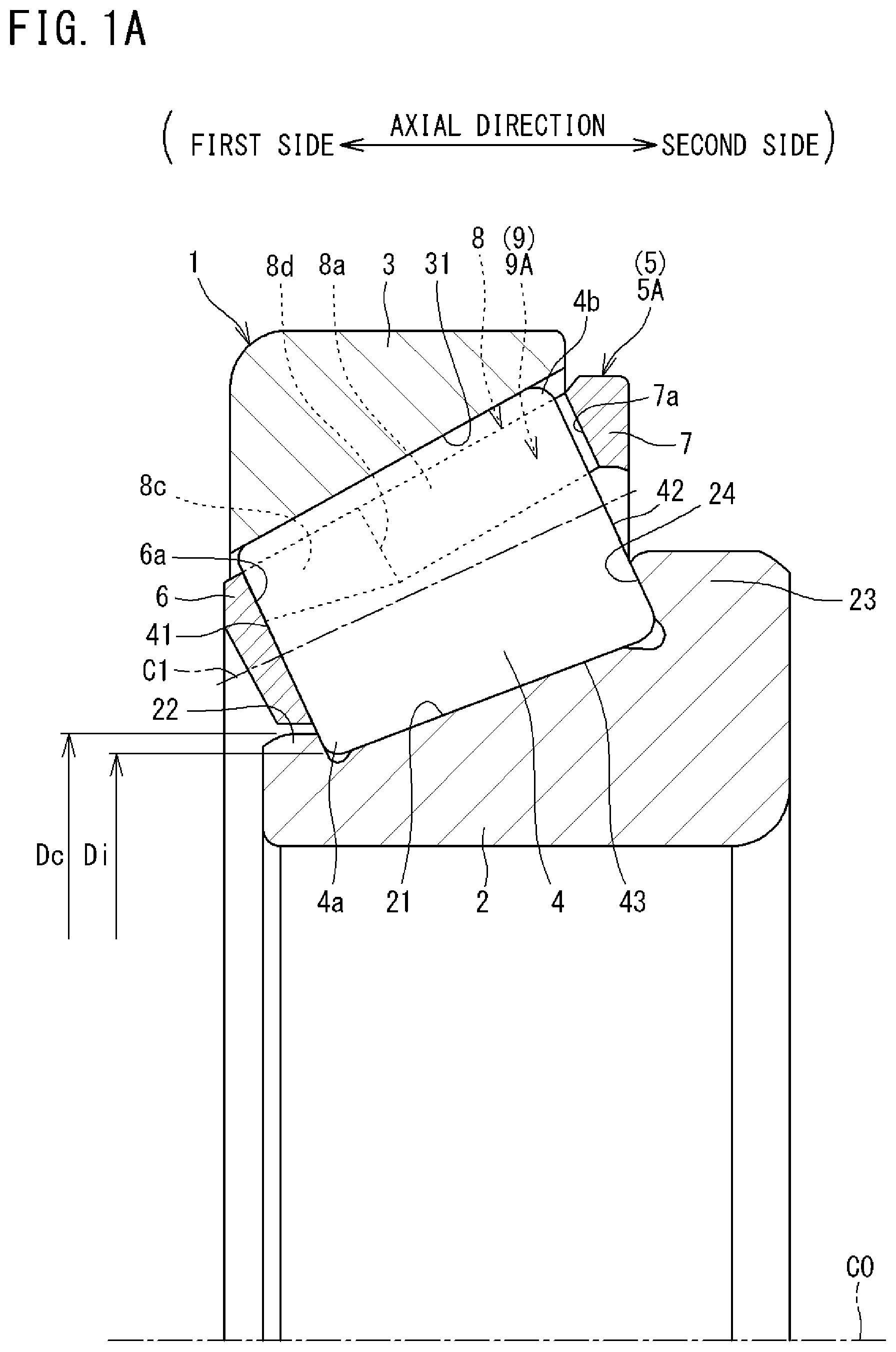
Here, a configuration of a tapered roller bearing 1 according to the present disclosure will be described based on the tapered roller bearing 1 illustrated in A, 1 B, 2 A , and 2 B. The tapered roller bearing 1 illustrated in A, 1 B, 2 A, and 2 B includes a cage 5 A which is a first mode of a cage 5 . In the following description, when a configuration common to the cage 5 A and cages 5 (later-described cages 5 B to 5 E) according to other modes to be described later is described, the cage 5 A is simply referred to as “cage 5 ”.
The tapered roller bearing 1 illustrated in A, 1 B, 2 A, and 2 B includes an inner ring 2 , an outer ring 3 provided radially outward of the inner ring 2 , a plurality of tapered rollers 4 provided between the inner ring 2 and the outer ring 3 , and an annular cage 5 that holds the tapered rollers 4 .
“Axial direction”, “radial direction”, and “circumferential direction” in the description of each of the inner ring 2 , the outer ring 3 , and the cage 5 will be defined. The “axial direction” refers to a direction along the centerline of each of the inner ring 2 , the outer ring 3 , and the cage 5 . The axial direction also includes a direction parallel to the centerline. The “radial direction” is a direction orthogonal to the centerline of each of the inner ring 2 , the outer ring 3 , and the cage 5 . The “circumferential direction” is a direction along a circle centered on the centerline of each of the inner ring 2 , the outer ring 3 , and the cage 5 . In each drawing, the centerline is denoted by “C 0 ” in a state where the centerlines of the inner ring 2 , the outer ring 3 , and the cage 5 coincide with each other.
“Axial direction”, “radial direction”, and “circumferential direction” in the description of the tapered roller 4 will be defined. The “axial direction” of the tapered roller 4 is a direction along the centerline C 1 of the tapered roller 4 . In order to distinguish the axial direction from the axial direction of the inner ring 2 , the outer ring 3 , and the cage 5 , the axial direction of the cage 5 and the like may be simply referred to as an “axial direction”, and the axial direction of the tapered roller 4 may be referred to as a “roller axial direction”. The roller axial direction also includes a direction parallel to the centerline C 1 . The “radial direction” is a direction orthogonal to the centerline C 1 of the tapered roller 4 , and may be referred to as a “roller radial direction”. The “circumferential direction” is a direction along a circle centered on the centerline C 1 of the tapered roller 4 , and can be referred to as a “roller circumferential direction”.
The inner ring 2 is an annular member formed using bearing steel, mechanical structural steel, or the like. The inner ring 2 has a tapered inner ring raceway 21 on the outer peripheral side thereof. The inner ring 2 includes a small flange portion 22 provided on a first side (left side in A and 2 A , right side in B and 2 B ) of the inner ring raceway 21 in the axial direction and a large flange portion 23 provided on a second side of the inner ring raceway 21 (right side in A and 2 A , left side in B and 2 B ) in the axial direction. Each of the small flange portion 22 and the large flange portion 23 protrudes outward in the radial direction. In a state where the plurality of tapered rollers 4 is retained by the cage 5 and located between the inner ring 2 and the outer ring 3 , the diameter Di of the inscribed circle at small-diameter-side portions 4 a of the plurality of tapered rollers 4 is smaller than the outer diameter Dc of the small flange portion 22 .
The outer ring 3 is an annular member formed using bearing steel, mechanical structural steel, or the like. The outer ring 3 has a tapered outer ring raceway 31 on the inner peripheral side thereof.
Each of the tapered rollers 4 is a tapered trapezoidal member formed using bearing steel or the like. Each of the tapered rollers 4 has a small-diameter-side end face 41 having a small diameter on a first side (left side in A and 2 A , right side in B and 2 B ) in the roller axial direction and a large-diameter-side end face 42 having a large diameter on a second side (right side in A and 2 A , left side in B and 2 B ) in the roller axial direction. The tapered rollers 4 are in rolling contact with the inner ring raceway 21 and the outer ring raceway 31 . The large-diameter-side end faces 42 are in sliding contact with a lateral face (flange face) 24 of the large flange portion 23 .
The cage 5 includes a small-diameter annular body 6 on the first side in the axial direction, a large-diameter annular body 7 on the second side in the axial direction, the large-diameter annular body 7 having an outer diameter larger than that of the small-diameter annular body 6 , and a plurality of columns 8 provided at intervals in the circumferential direction (see ). The small-diameter annular body 6 and the large-diameter annular body 7 have an annular shape and are provided apart from each other in the axial direction. The columns 8 connect the small-diameter annular body 6 and the large-diameter annular body 7 . A space formed between the small-diameter annular body 6 and the large-diameter annular body 7 and between the two columns 8 and 8 adjacent to each other in the circumferential direction is a pocket 9 . One tapered roller 4 is accommodated in each pocket 9 .
The cage 5 has a plurality of pockets 9 for accommodating the tapered rollers 4 , and holds the plurality of tapered rollers 4 at equal intervals in the circumferential direction. As will be described later, the cage 5 has two types of pockets 9 (“first pocket” and “second pocket”) having different shapes.
The lateral faces of the two columns 8 and 8 face each other inside the pocket 9 . A lateral face of one of the two columns 8 and 8 is a first lateral face 8 a facing the outer peripheral surface 43 of the tapered roller 4 accommodated in the pocket 9 from the first side in the circumferential direction, and a lateral face of the other column 8 is a second lateral face 8 b facing the outer peripheral surface 43 of the tapered roller 4 accommodated in the pocket 9 from the second side in the circumferential direction. The first lateral face 8 a and the second lateral face 8 b form a predetermined angle such that the distance between the lateral faces decreases toward the outside in the radial direction of the cage 5 . The first lateral face 8 a and the second lateral face 8 b serve as retaining portions that prevent the tapered roller 4 accommodated in the pocket 9 from falling outside in the radial direction.
The small-diameter annular body 6 has small-diameter-side lateral faces 6 a . Each of the small-diameter-side lateral faces 6 a is a portion facing the small-diameter-side end face 41 of the tapered roller 4 accommodated in each of the pockets 9 . As will be described later, when the tapered roller 4 accommodated in the pocket 9 is inclined, the small-diameter-side lateral face 6 a has a function of restricting displacement of the small-diameter-side portion 4 a of the tapered roller 4 toward the outside in the radial direction.
The large-diameter annular body 7 has large-diameter-side lateral faces 7 a . Each of the large-diameter-side lateral faces 7 a is a portion facing the large-diameter-side end face 42 of the tapered roller 4 accommodated in each of the pockets 9 . As will be described later, when the tapered roller 4 accommodated in the pocket 9 is inclined, the large-diameter-side lateral face 7 a has a function of restricting displacement of the large-diameter-side portion 4 b of the tapered roller 4 toward the inside in the radial direction.
A space surrounded by the first lateral face 8 a , the second lateral face 8 b , the small-diameter-side lateral face 6 a , and the large-diameter-side lateral face 7 a is formed inside the pocket 9 . The conical outer peripheral surface 43 of the tapered roller 4 accommodated in the pocket 9 faces the first lateral face 8 a and the second lateral face 8 b . In the tapered roller 4 accommodated in the pocket 9 , the small-diameter-side end face 41 faces the small-diameter-side lateral face 6 a , and the large-diameter-side end face 42 faces the large-diameter-side lateral face 7 a.
The cage 5 is made of synthetic resin and is molded by injection molding. The cage 5 according to the present embodiment is made of, for example, polyphenylene sulfide resin (PPS). The cage 5 has resistance to lubricating oil (oil resistance), is relatively hard, and is hardly elastically deformed. The cage 5 may be manufactured by a 3D printer.
In the present disclosure, the cage 5 can be in sliding contact with a part of the inner peripheral surface of the outer ring 3 , whereby the rotation of the cage 5 is guided by the outer ring 3 . That is, the tapered roller bearing 1 illustrated in is an outer ring guided bearing in which the cage 5 is guided by the outer ring 3 .
A state in which the centerline of the cage 5 coincides with the centerline of the inner ring 2 and the plurality of tapered rollers 4 held by the cage 5 appropriately contact the inner ring raceway 21 and the lateral face 24 of the large flange portion 23 as illustrated in A, 1 B, 2 A, and 2 B is defined as a “reference state”. In a state in which the tapered rollers 4 are in contact with the outer ring raceway 31 in the reference state, the tapered rollers 4 are not displaceable in the roller radial direction and the roller axial direction. In the reference state, a gap is provided between the small-diameter-side end face 41 of the tapered roller 4 and the small-diameter annular body 6 , and a gap is provided between the outer peripheral surface 43 of the tapered roller 4 and each of the lateral faces 8 a and 8 b of the columns 8 . Therefore, the cage 5 can be slightly displaced in the radial direction and the axial direction with respect to the tapered rollers 4 . In addition, the tapered rollers 4 can be slightly displaced in the axial direction and the radial direction from the reference state (see A and 4 B ) in which the outer ring 3 is removed.
In the reference state, an imaginary circle connecting the centers of the small-diameter-side end faces 41 of the plurality of tapered rollers 4 is defined as a pitch circle on the small diameter side (in design) of the tapered rollers 4 , and an imaginary circle connecting the centers of the large-diameter-side end faces 42 of the plurality of tapered rollers 4 is defined as a pitch circle on the large diameter side (in design) of the tapered rollers 4 . An assembly (see A ) in which the tapered rollers 4 are accommodated in the pockets 9 of the cage 5 is a “set 10 ” of the cage 5 and the tapered rollers 4 . An assembly (see B ) obtained by combining the set 10 and the inner ring 2 is an “inner ring unit 11 ”.
In each of the set 10 and the inner ring unit 11 , the plurality of tapered rollers 4 is arranged along the pitch circle on the small diameter side and the pitch circle on the large diameter side, unless otherwise specified. In the present disclosure, this state may be simply described as a state in which the tapered rollers 4 are disposed “along the pitch circle”. Each of the tapered rollers 4 can be slightly displaced while being displaced radially outward from a state of being arranged along the pitch circle until coming into contact with each of the lateral faces 8 a and 8 b of the columns 8 .
[Recessed Portion]
The tapered roller bearing 1 needs to cause deflection of the columns 8 during assembly. As illustrated in A, 1 B, 2 A, and 2 B , a recessed portion 8 c is formed on each of the first lateral face 8 a and the second lateral face 8 b of the column 8 in the cage 5 . The thickness of the recessed portion 8 c of the column 8 in the circumferential direction is smaller than the thickness of a portion other than the recessed portion 8 c of the column 8 in the circumferential direction. For this reason, a force required to generate certain deflection on the column 8 in the circumferential direction and in the radial direction is smaller than a force required to generate certain deflection on a column having no recessed portion 8 c.
The recessed portion 8 c is provided on the first side in the axial direction of the first lateral face 8 a and the second lateral face 8 b , and is adjacent to the small-diameter annular body 6 . The recessed portion 8 c forms a part of a space that receives the small-diameter-side portion 4 a of the tapered roller 4 which is accommodated in the pocket 9 and which is inclined so as to be displaced outward in the radial direction of the cage 5 . Due to having the recessed portion 8 c , the cage 5 does not prevent the displacement of the tapered roller 4 when the small-diameter-side portion 4 a of the tapered roller 4 is displaced radially outward due to the tapered roller 4 in the pocket 9 coming into contact with the small flange portion 22 of the inner ring 2 during the operation of combining the set 10 and the inner ring 2 . Therefore, due to the formation of the recessed portion 8 c , the pocket 9 provides a larger allowable amount of displacement of the small-diameter-side portion 4 a to the outside in the radial direction of the cage 5 , as compared to the case where the recessed portion 8 c is not provided.
The column 8 has a ridgeline formed at a boundary between each of the first lateral face 8 a and the second lateral face 8 b and the recessed portion 8 c . In this description, a portion where the ridgeline is formed is referred to as a boundary portion 8 d . During assembly of the tapered roller bearing 1 , the tapered roller 4 accommodated in the pocket 9 is inclined such that the small-diameter-side portion 4 a thereof is displaced outward of the cage 5 in the radial direction. At this time, the tapered roller 4 comes into contact with the boundary portion 8 d . The boundary portion 8 d comes into contact with the tapered roller 4 and serves as a supporting point when the tapered roller 4 is inclined.
In the configuration in which the recessed portion 8 c is formed on the first side in the axial direction of the first lateral face 8 a and the second lateral face 8 b , the boundary portion 8 d can be located at a position closer to the center side from the end of each of the lateral faces 8 a and 8 b in the longitudinal direction of the column 8 . As a result, when the tapered roller 4 accommodated in the pocket 9 is inclined and comes into contact with the boundary portion 8 d between the first lateral face 8 a and the second lateral face 8 b , the tapered roller 4 presses the position near the center of the column 8 in the longitudinal direction.
[Small-Diameter-Side Lateral Face and Large-Diameter-Side Lateral Face]
When the tapered roller 4 is inclined at a predetermined inclination or more in a case where the tapered roller 4 accommodated in the pocket 9 is inclined such that the small-diameter-side portion 4 a is displaced outward of the cage 5 in the radial direction with the boundary portion 8 d as a supporting point, the small-diameter-side end face 41 comes into contact with the small-diameter-side lateral face 6 a , and the large-diameter-side end face 42 comes into contact with the large-diameter-side lateral face 7 a . The small-diameter-side lateral face 6 a restricts displacement of the small-diameter-side portion 4 a to the outside in the radial direction, and the large-diameter-side lateral face 7 a restricts displacement of the large-diameter-side portion 4 b to the inside in the radial direction.
As described above, in the cage 5 , the allowable amount of displacement of the small-diameter-side portion 4 a of the tapered roller 4 accommodated in the pocket 9 to the outside of the cage 5 in the radial direction is increased by the recessed portion 8 c , and the displacement can be restricted by the small-diameter-side lateral face 6 a and the large-diameter-side lateral face 7 a.
[First Mode of Cage]
A cage 5 A according to the first mode will now be described. In the following description, a “first pocket” in the cage 5 A is referred to as a first pocket 9 A, and a “second pocket” in the cage 5 A is referred to as a second pocket 9 B to be distinguished from “first pockets” and “second pockets” in the cages 5 according to the other modes.
As illustrated in , the cage 5 A includes the first pocket 9 A and the second pocket 9 B which are two types of pockets 9 having different shapes.
A and 4 B are diagrams partially illustrating a cross section of the cage 5 including a centerline. A is a diagram illustrating a cross section including the first pocket 9 A, and B is a diagram illustrating a cross section including the second pocket 9 B. As illustrated in A and 4 B , the first pocket 9 A has a first distance L 1 as a distance from the small-diameter-side lateral face 6 a to the large-diameter-side lateral face 7 a , and the second pocket 9 B has a second distance L 2 as a distance from the small-diameter-side lateral face 6 a to the large-diameter-side lateral face 7 a . In the cage 5 A, the second distance L 2 is larger than the first distance L 1 (L 2 >L 1 ). Therefore, in the cage 5 A, in a state where the dimension of the gap between the small-diameter-side lateral face 6 a and the small-diameter-side end face 41 is the same between the first pocket 9 A and the second pocket 9 B, the tapered roller 4 accommodated in the second pocket 9 B has a larger gap between the large-diameter-side end face 42 and the large-diameter-side lateral face 7 a than the tapered roller 4 accommodated in the first pocket 9 A.
Since there is the gap between the large-diameter-side end face 42 and the large-diameter-side lateral face 7 a , the large-diameter-side portions 4 b of the tapered rollers 4 accommodated in the pockets 9 A and 9 B are allowed to be displaced (inclined) in the axial direction or the radial direction while being displaced to the inside of the cage 5 in the radial direction. When the tapered rollers 4 are inclined in this manner, the displacement of the large-diameter-side portions 4 b to the inside in the radial direction increases with an increase in the displacement of the large-diameter-side portions 4 b in the axial direction.
The tapered roller 4 accommodated in the second pocket 9 B has a larger gap between the large-diameter-side end face 42 and the large-diameter-side lateral face 7 a than the tapered roller 4 accommodated in the first pocket 9 A because of the relationship of L 2 >L 1 . For this reason, in the second pocket 9 B, the allowable amount of displacement of the large-diameter-side portion 4 b to the inside in the radial direction accompanying the displacement in the axial direction is larger than that in the first pocket 9 A.
When the tapered roller 4 accommodated in each of the pockets 9 A and 9 B is inclined such that the large-diameter-side portion 4 b is displaced radially inward, the small-diameter-side portion 4 a located on the opposite side in the axial direction is displaced radially outward while being displaced in the axial direction accordingly. When the displacement of the large-diameter-side portion 4 b to the inside in the radial direction increases, the displacement of the small-diameter-side portion 4 a to the outside in the radial direction also increases. Therefore, the tapered roller 4 accommodated in the second pocket 9 B has a larger allowable amount of displacement of the small-diameter-side portion 4 a to the outside in the radial direction than the tapered roller 4 accommodated in the first pocket 9 A.
Here, the allowable amount of displacement of the small-diameter-side portion 4 a of the tapered roller 4 accommodated in the first pocket 9 A to the outside in the radial direction is defined as a “first displacement amount X 1 ” (see A ), and the allowable amount of displacement of the small-diameter-side portion 4 a of the tapered roller 4 accommodated in the second pocket 9 B to the outside in the radial direction is defined as a “second displacement amount Y 1 ” (see B ). The “first displacement amount X 1 ” and the “second displacement amount Y 1 ” can also be said to be a displaceable amount of the tapered roller 4 , which is positioned along the pitch circle, to the outside in the radial direction.
In the cage 5 A according to the present disclosure, the second distance L 2 is larger than the first distance L 1 (L 2 >L 1 ). Therefore, the “second displacement amount Y 1 ” is larger than the “first displacement amount X” (Y 1 >X 1 ). Thus, the tapered roller 4 accommodated in the second pocket 9 B of the cage 5 A has a larger diameter Di of the inscribed circle at the small-diameter-side portion 4 a than the tapered roller 4 accommodated in the first pocket 9 A of the cage 5 A.
In the cage 5 A described in the above description, the relationship of L 2 >L 1 is obtained by recessing the large-diameter annular body 7 in the second pocket 9 B to form the large-diameter-side lateral face 7 a . However, the relationship of L 2 >L 1 is obtained by recessing the small-diameter annular body 6 in the second pocket 9 B to form the small-diameter-side lateral face 6 a.
In the cage 5 A, the supporting point (contact point with the boundary portion 4 d ) of the tapered roller 4 when the tapered roller 4 accommodated in the second pocket 9 B is inclined such that the small-diameter-side portion 4 a is displaced radially outward is located closer to the small-diameter-side end face 41 . In this case, the distance from the supporting point to the large-diameter-side portion 4 b is larger than the distance from the supporting point to the small-diameter-side portion 4 a , and thus, the displacement of a radially outer part of the large-diameter-side portion 4 b to the second side in the axial direction during inclination of the tapered roller 4 is larger than the displacement of a radially inner part of the small-diameter-side portion 4 a to the first side in the axial direction. Therefore, the inclination of the tapered roller 4 can be increased more by increasing the gap on the side of the large-diameter-side portion 4 b rather than by increasing the gap on the side of the small-diameter-side portion 4 a . Thus, in order to further increase the “second displacement amount Y 1 ” of the second pocket 9 B, it is preferable to obtain the relationship of L 2 >L 1 by recessing the large-diameter annular body 7 in the second pocket 9 B to form the large-diameter-side lateral face 7 a rather than by recessing the small-diameter annular body 6 in the second pocket 9 B to form the small-diameter-side lateral face 6 a.
[Second Mode of Cage]
A cage 5 B according to the second mode will now be described. In the following description, a “first pocket” in the cage 5 B is referred to as a first pocket 9 C, and a “second pocket” in the cage 5 B is referred to as a second pocket 9 D to be distinguished from the “first pockets” and the “second pockets” in the cages 5 according to the other modes.
As illustrated in , the cage 5 B includes the first pocket 9 C and the second pocket 9 D which are two types of pockets 9 having different shapes.
As illustrated in , in the cage 5 B, the first pocket 9 C has a first angle θ 1 as the angle formed by the first lateral face 8 a and the second lateral face 8 b , and the second pocket 9 D has a second angle θ 2 as the angle formed by the first lateral face 8 a and the second lateral face 8 b . In the cage 5 B, the second angle θ 2 is smaller than the first angle θ 1 (θ 2 <θ 1 ). Each of the angles θ 1 and 02 is an angle formed by a line passing through the upper end and the lower end of the first lateral face 8 a and a line passing through the upper end and the lower end of the second lateral face 8 b in the cross section of the cage 5 B taken along a plane perpendicular to the roller axial direction (see A and 6 B ). Further, the angles 81 and 02 are constant along the roller axial direction on the first lateral face 8 a and the second lateral face 8 b excluding the recessed portion 8 c.
As illustrated in A , in the first pocket 9 C, a gap D 1 is provided between the tapered roller 4 located along the pitch circle and each of the first lateral face 8 a and the second lateral face 8 b in relation to the radial direction of the tapered roller 4 . In the first pocket 9 C, a first gap K 1 is provided between the tapered roller 4 located along the pitch circle and each of the first lateral face 8 a and the second lateral face 8 b in relation to the radial direction of the cage 5 B. The first gap K 1 is a gap at a position where the first lateral face 8 a and the second lateral face 8 b can come into contact with the tapered roller 4 . Due to the first gap K 1 , the tapered roller 4 in the first pocket 9 C is allowed to have displacement having a radial component. Here, an allowable amount of the displacement is defined as “first displacement amount X 2 ”. The “first displacement amount X 2 ” can also be said to be a displaceable amount of the tapered roller 4 , which is positioned along the pitch circle, to the outside in the radial direction.
As illustrated in B , in the second pocket 9 D, a gap D 2 is provided between the tapered roller 4 located along the pitch circle and each of the first lateral face 8 a and the second lateral face 8 b in relation to the radial direction of the tapered roller 4 . In the second pocket 9 D, a second gap K 2 is provided between the tapered roller 4 located along the pitch circle and each of the first lateral face 8 a and the second lateral face 8 b in relation to the radial direction of the cage 5 B. The second gap K 2 is a gap at a position where the first lateral face 8 a and the second lateral face 8 b can come into contact with the tapered roller 4 . Due to the second gap K 2 , the tapered roller 4 in the second pocket 9 D is allowed to have displacement having a radial component. Here, an allowable amount of the displacement is defined as “second displacement amount Y 2 ”. The “second displacement amount Y 2 ” can also be said to be a displaceable amount of the tapered roller 4 , which is positioned along the pitch circle, to the outside in the radial direction. The gap D 1 in the first pocket 9 C is substantially equal to the gap D 2 in the second pocket 9 D.
In the cage 5 B according to the present disclosure, the second angle θ 2 is smaller than the first angle θ 1 (θ 2 <θ 1 ). Therefore, the second gap K 2 is larger than the first gap K 1 (K 2 >K 1 ), and thus, the “second displacement amount Y 2 ” is larger than the “first displacement amount X 2 ” (Y 2 >X 2 ). Therefore, the tapered roller 4 accommodated in the second pocket 9 D of the cage 5 B has a larger diameter Di of the inscribed circle at the small-diameter-side portion 4 a than the tapered roller 4 accommodated in the first pocket 9 C of the cage 5 B.
[Third Mode of Cage]
A cage 5 C according to the third mode will now be described. In the following description, a “first pocket” in the cage 5 C is referred to as a first pocket 9 E, and a “second pocket” in the cage 5 C is referred to as a second pocket 9 F to be distinguished from the “first pockets” and the “second pockets” in the cages 5 according to the other modes. In the following description, portions of the cage 5 C common to those of the cages 5 A and 5 B are denoted by the reference numerals used in the description of the cages 5 A and 5 B, and the description thereof will be omitted unless otherwise specified.
As illustrated in , the cage 5 C includes the first pocket 9 E and the second pocket 9 F which are two types of pockets 9 having different shapes.
Although not illustrated in , the cage 5 C includes:
•
• a configuration common to the cage 5 A in which the second distance L 2 is larger than the first distance L 1 ; and • a configuration common to the cage 5 B in which the second angle θ 2 is smaller than the first angle θ 1 and the second gap K 2 is larger than the first gap KL.
The first pocket 9 E has the first distance L 1 (see A ) as the distance from the small-diameter-side lateral face 6 a to the large-diameter-side lateral face 7 a , and has the first angle θ 1 (see A ) as the angle formed by the first lateral face 8 a and the second lateral face 8 b . The second pocket 9 F has the second distance L 2 (see B ) as the distance from the small-diameter-side lateral face 6 a to the large-diameter-side lateral face 7 a , and has the second angle θ 2 (see B ) as the angle formed by the first lateral face 8 a and the second lateral face 8 b . In the cage 5 C, the second distance L 2 is larger than the first distance L 1 . In the cage 5 C, the second angle θ 2 is smaller than the first angle θ 1 , and the second gap K 2 is larger than the first gap KL.
In the cage 5 C according to the present disclosure, the second distance L 2 is larger than the first distance L 1 (L 2 >L 1 ), and the second gap K 2 is larger than the first gap K 1 (K 2 >K 1 ). Therefore, in the cage 5 C, the “second displacement amount” is larger than the “first displacement amount” as in the cage 5 A and the cage 5 B. Thus, the tapered roller 4 accommodated in the second pocket 9 F of the cage 5 C has a larger diameter Di of the inscribed circle at the small-diameter-side portion 4 a than the tapered roller 4 accommodated in the first pocket 9 E of the cage 5 C.
In the cage 5 C according to the present disclosure, the relationship between the first distance L 1 and the second distance L 2 and the relationship between the first angle θ 1 and the second angle θ 2 can be adjusted, so that the “first displacement amount” and the “second displacement amount” can finely be adjusted. In the cage 5 C according to the present disclosure, each of the pockets 9 E and 9 F has both the configuration in which the second distance L 2 is larger than the first distance L 1 and the configuration in which the second angle θ 2 is smaller than the first angle θ 1 and the second gap K 2 is larger than the first gap K 1 . However, the pockets 9 E and 9 F each having only one of the above configurations may be uniformly distributed.
As described above, the pockets 9 including the “first pocket” and the “second pocket” in each of the cages 5 A, 5 B, and 5 C according to the present disclosure vary in allowable amounts of displacement of the tapered rollers 4 accommodated therein in the radial direction. Specifically, each of the cages 5 A, 5 B, and 5 C has the “first pocket” having the “first displacement amount” as the allowable amount of displacement and the “second pocket” having, as the allowable amount of displacement, the “second displacement amount” larger than the “first displacement amount”.
[Displacement of Tapered Roller 4 ]
A illustrates a state in which the plurality of tapered rollers 4 is arranged along the pitch circle as described above. On the other hand, B illustrates a state in which the plurality of tapered rollers 4 is not arranged along the pitch circle, and each of the tapered rollers 4 is displaced for the “first displacement amount” or the “second displacement amount”. That is, B illustrates a state in which each of the tapered rollers 4 is in contact with the first lateral face 8 a and the second lateral face 8 b . B does not illustrate the cage 5 A. The tapered roller 4 in the first pocket 9 A and the tapered roller 4 in the second pocket 9 B are hatched, and they are distinguished from each other by changing the hatch density. In B , an inscribed circle at the small-diameter-side portions 4 a of the tapered rollers 4 accommodated in the first pockets 9 A and in contact with the first lateral faces 8 a and the second lateral faces 8 b is defined as Q 1 . An inscribed circle at the small-diameter-side portions 4 a of the tapered rollers 4 accommodated in the second pockets 9 B and in contact with the first lateral faces 8 a and the second lateral faces 8 b is defined as Q 2 .
As described above, in the cage 5 A, the “first displacement amount” and the “second displacement amount” are different, and thus, the diameter of the first inscribed circle Q 1 and the diameter of the second inscribed circle Q 2 are different (the diameter of the inscribed circle Q 2 >the diameter of the inscribed circle Q 1 ). In , the outer diameter (maximum outer diameter) Dc of the small flange portion 22 of the inner ring 2 may be equal to or smaller than the diameter of the second inscribed circle Q 2 and equal to or larger than the diameter of the first inscribed circle Q 1 . However, in the present disclosure, the outer diameter (maximum outer diameter) Dc is equal to or larger than the diameter of the first inscribed circle Q 1 and equal to or larger than the diameter of the second inscribed circle Q 2 . Although the tapered rollers 4 accommodated in the first pocket 9 A and the second pocket 9 B of the cage 5 A have been described here as an example, the displacement of the tapered rollers 4 accommodated in the first pocket 9 C and the second pocket 9 D of the cage 5 B and the displacement of the tapered rollers 4 accommodated in the first pocket 9 E and the second pocket 9 F of the cage 5 C can be similarly described.
[Arrangement of Pockets in Circumferential Direction]
In A , the tapered roller 4 in the first pocket 9 A and the tapered roller 4 in the second pocket 9 B are hatched, and they are distinguished from each other by changing the hatch density. The cage 5 A illustrated in A has a total of 17 pockets 9 . Eight pockets in the 17 pockets are the second pockets 9 B and the remaining nine pockets are the first pockets 9 A. The second pockets 9 B are spaced from each other in the circumferential direction of the cage 5 A with one or more first pockets 9 A therebetween. The pockets 9 A and 9 B in the cage 5 A may be disposed as illustrated in .
The cage 5 A illustrated in has a total of 16 pockets 9 . Eight pockets which are a half of the 16 pockets are the second pockets 9 B and the remaining eight pockets are the first pockets 9 A. The second pockets 9 B are spaced from each other in the circumferential direction of the cage 5 A with one first pocket 9 A therebetween. In the cage 5 A, it is preferable that the first pockets 9 A and the second pockets 9 B are disposed as uniformly as possible in the circumferential direction. However, the first pockets 9 A and the second pockets 9 B may not be arranged completely uniformly like the cage 5 A illustrated in . For example, in the cage 5 A illustrated in A , there is one portion in which two first pockets 9 A are consecutive between the second pockets 9 B, but the first pockets 9 A and the second pockets 9 B disposed as described above with such a variation can be considered to be disposed uniformly in the circumferential direction.
In the cage 5 A, the second pockets 9 B are spaced from each other in the circumferential direction with the first pocket 9 A therebetween. With this configuration, the first pockets 9 A and the second pockets 9 B are disposed uniformly in the circumferential direction of the cage 5 . This configuration can suppress a variation in force applied to the cage 5 A in the circumferential direction when the set 10 and the inner ring 2 are combined. Accordingly, intensive application of force on a part of the cage 5 during the operation of combining the set 10 and the inner ring 2 can be prevented. If a force is intensively applied to a part of the cage 5 , a portion where the force is applied may be whitened or plastically deformed, or a crack may occur in the cage 5 . However, the cage 5 can suppress an occurrence of defect such as a crack. Although the arrangement of the first pockets 9 A and the second pockets 9 B of the cage 5 A has been described here as an example, the arrangement of the first pockets 9 C and the second pockets 9 D of the cage 5 B and the arrangement of the first pockets 9 E and the second pockets 9 F of the cage 5 C can be similarly described.
[Number of First Pockets and Second Pockets]
In the cage 5 A illustrated in A , the number of the first pockets 9 A is larger than the number of the second pockets 9 B, and in the cage 5 A illustrated in , the number of the first pockets 9 A and the number of the second pockets 9 B are the same. However, in the cage 5 A according to the present disclosure, the number of the second pockets 9 B may be larger than the number of the first pockets 9 A. For example, when the number of the second pockets 9 B is smaller than the number of the first pockets 9 A as illustrated in A , it is possible to obtain a configuration in which the cage 5 is less likely to be displaced with respect to the inner ring 2 . On the other hand, when the number of the second pockets 9 B is larger than that of the first pockets 9 A, it is possible to obtain a configuration that further facilitates the operation of combining the set 10 with the inner ring 2 . Although the numbers of the first pockets 9 A and the second pockets 9 B of the cage 5 A have been described here as an example, the numbers of the first pockets 9 C and the second pockets 9 D of the cage 5 B and the numbers of the first pockets 9 E and the second pockets 9 F of the cage 5 C can be similarly described.
[Assembly of Tapered Roller Bearing 1 ]
The tapered roller bearing 1 having the above configuration is assembled as follows. In the present disclosure, a procedure for assembling the tapered roller bearing 1 will be described based on the tapered roller bearing 1 including the cage 5 A, but the tapered roller bearing 1 including the cage 5 B or 5 C can also be assembled in the same procedure as that for the tapered roller bearing 1 including the cage 5 A.
As illustrated in A , the tapered rollers 4 are accommodated in the pockets 9 A and 9 B from the inner peripheral side of the cage 5 A, and the cage 5 A and the tapered rollers 4 are combined. Thus, a set 10 of the plurality of tapered rollers 4 and the cage 5 A is obtained. The set 10 is brought close to the inner ring 2 in the axial direction (see B ) and is combined with the inner ring 2 . In the state of the set 10 and at the time of installing the set 10 , the tapered roller 4 accommodated in each of the pockets 9 A and 9 B is prevented from falling outward in the radial direction by the first lateral face 8 a and the second lateral face 8 b of the column 8 in each of the pockets 9 A and 9 B.
is an image diagram for describing the positions of the tapered rollers 4 in the first pocket 9 A and the second pocket 9 B. In the set 10 , the diameter Di of the inscribed circle at the small-diameter-side portions 4 a of the plurality of tapered rollers 4 located along the pitch circle is smaller than the outer diameter Dc of the small flange portion 22 of the inner ring 2 as illustrated in A and 12 .
Further, the diameter Dj 1 (see ) of the inscribed circle Q 1 at the small-diameter-side portions 4 a in a state where the tapered rollers 4 accommodated in the first pockets 9 A are displaced radially outward and the diameter Dj 2 (see ) of the inscribed circle Q 2 at the small-diameter-side portions 4 a in a state where the tapered rollers 4 accommodated in the second pockets 9 B are displaced radially outward are smaller than the outer diameter Dc of the small flange portion 22 of the inner ring 2 . For this reason, during the operation of combining the set 10 with the inner ring 2 (see B ), the small-diameter-side portions 4 a of the tapered rollers 4 need to climb over the small flange portion 22 , so that they are displaced radially outward. In order to allow the small-diameter-side portions 4 a of the tapered rollers 4 to climb over the small flange portion 22 , the inner ring 2 is pressed against the cage 5 A in the axial direction to elastically deform a part of the cage 5 A.
As illustrated in A , each of the tapered rollers 4 oscillates in a clockwise direction in A with a contact point with the boundary portion 8 d as a supporting point. That is, the tapered rollers 4 oscillate such that the small-diameter-side portions 4 a move radially outward. The displacement of the tapered rollers 4 accompanying oscillation as described above makes it easy for the small-diameter-side portions 4 a to climb over the small flange portion 22 .
Further, the cage 5 A has two types of pockets 9 A and 9 B as described above. As described above, the second pocket 9 B has the second displacement amount Y 1 as the allowable amount of displacement having a radial component, and the second displacement amount Y 1 is larger than the allowable amount of displacement (first displacement amount X 1 ) in the first pocket 9 A. That is, as compared with the tapered roller 4 in the first pocket 9 A, the tapered roller 4 in the second pocket 9 B has a larger allowable amount of displacement having a radial component. For this reason, in the second pocket 9 B, only a small “elastic deformation amount (see the left diagram of )” is required in a part of the cage 5 A, and the tapered roller 4 in the second pocket 9 B easily climbs over the small flange portion 22 during the operation of combining the set 10 with the inner ring 2 . This facilitates the operation of combining the set 10 with the inner ring 2 . Even when the pressing force of the inner ring 2 in the axial direction is small, the small-diameter-side portions 4 a of the tapered rollers 4 can easily climb over the small flange portion 22 .
Each of the pockets 9 A and 9 B has the recessed portion 8 c in the first lateral face 8 a and the second lateral face 8 b . A force required to generate certain deflection in the circumferential direction on the column 8 having the recessed portion 8 c is smaller than a force required to generate deflection on a column having no recessed portion 8 c , and thus, only a small force is required to elastically deform a part of the cage 5 A. Therefore, the tapered rollers 4 in the pockets 9 A and 9 B climb over the small flange portion 22 with a smaller force than in a case where the recessed portion 8 c is not provided. Thus, even when the pressing force of the inner ring 2 in the axial direction is small, the small-diameter-side portions 4 a of the tapered rollers 4 can easily climb over the small flange portion 22 . This further facilitates the operation of combining the set 10 with the inner ring 2 .
In each of the pockets 9 A and 9 B, the recessed portion Sc is formed on the first side in the axial direction of the first lateral face 8 a and the second lateral face 8 b . In this configuration, when the tapered roller 4 accommodated in each of the pockets 9 A and 9 B is inclined and comes into contact with the boundary portion 8 d between the first lateral face 8 a and the second lateral face 8 b , the tapered roller 4 can press the position near the center of the column 8 in the longitudinal direction. A smaller force is required to generate certain deflection in the circumferential direction and in the radial direction of the cage 5 A when the position near the center of the column 8 in the longitudinal direction is pressed than when the end of the column 8 in the longitudinal direction is pressed. Therefore, the cage 5 A can be elastically deformed with a smaller force. Thus, even when the pressing force of the inner ring 2 in the axial direction is small, the small-diameter-side portions 4 a of the tapered rollers 4 can easily climb over the small flange portion 22 . This further facilitates the operation of combining the set 10 with the inner ring 2 .
When the set 10 and the inner ring 2 are combined to obtain the inner ring unit 11 as illustrated in B , the tapered roller 4 in the first pocket 9 A is less likely to be displaced relative to the cage 5 A. This is because the first pocket 9 A has the “first displacement amount” smaller than the “second displacement amount” as the allowable amount of displacement having the radial component of the tapered roller 4 as illustrated in . The cage 5 A is less likely to be displaced with respect to the inner ring 2 , whereby not only the tapered roller 4 retained in the first pocket 9 A of the cage 5 A but also the tapered roller 4 retained in the second pocket 9 B are less likely to be displaced in the radial direction as a whole. In the first pocket 9 A in the inner ring unit 11 , an external force large enough to generate a large “elastic deformation amount (see the right diagram of )” in a part of the cage 5 A is required in order to allow the tapered roller 4 to climb over the small flange portion 22 , so that it is difficult for the tapered roller 4 to climb over the small flange portion 22 .
In the state of the inner ring unit 11 illustrated in B , when the tapered roller 4 in each of the pockets 9 is inclined to be displaced in the radial direction, the displacement is restricted by the small-diameter-side lateral face 6 a . Therefore, the inner ring unit 11 is less likely to come apart.
According to the above assembling method, the inner ring unit 11 in which the inner ring 2 , the cage 5 A, and the tapered rollers 4 are integrated is obtained. The outer ring 3 is installed to the inner ring unit 11 , and thus, the tapered roller bearing 1 is completed.
If all the pockets 9 of the cage 5 A are the first pockets 9 A each having a smaller allowable amount of displacement than the second pocket 9 B, a large force (load) is required for combining the set 10 with the inner ring 2 during the operation of combining the set 10 with the inner ring 2 . Thus, the operation of combining them is difficult. Alternatively, if all the pockets 9 of the cage 5 A are the second pockets 9 B each having a larger allowable amount of displacement than the first pocket 9 A, the tapered rollers 4 and the cage 5 A in the inner ring unit 11 are likely to come apart from the inner ring 2 .
On the other hand, the plurality of pockets 9 included in the cage 5 A according to the present disclosure includes the first pocket 9 A having the “first displacement amount X 1 ” as the allowable amount of displacement and the second pocket 9 B having the “second displacement amount Y 1 ” larger than the “first displacement amount X 1 ” as the allowable amount of displacement. This configuration can achieve facilitating the operation of combining the set 10 of the cage 5 A and the plurality of tapered rollers 4 with the inner ring 2 and preventing the inner ring unit 11 obtained by combining the set 10 with the inner ring 2 from coming apart.
[First Modification of Cage]
A cage 5 D according to a modification will be described with reference to A and 13 B . In the following description, a “first pocket” in the cage 5 D is referred to as a first pocket 9 G, and a “second pocket” in the cage 5 D is referred to as a second pocket 9 H to be distinguished from the “first pockets” and the “second pockets” in the cages 5 according to the other modes. In the following description, portions of the cage 5 D common to those of the cages 5 A to 5 C are denoted by the reference numerals used in the description of the cages 5 A to 5 C, and the description thereof will be omitted unless otherwise specified.
A and 13 B are diagrams partially illustrating a cross section of the cage 5 D including a centerline C 0 . A is a diagram illustrating a cross section including the first pocket 9 G, and B is a diagram illustrating a cross section including the second pocket 9 H. Similar to the second pockets 9 B ( A or ) according to the first mode, the second pockets 9 H are spaced from each other in the circumferential direction of the cage 5 D with one or a plurality of first pockets 9 G interposed therebetween.
The cage 5 D includes a small-diameter annular body 60 on the first side in the axial direction, a large-diameter annular body 7 on the second side in the axial direction, and a plurality of columns 8 connecting the small-diameter annular body 60 and the large-diameter annular body 7 . The shape of the small-diameter annular body 60 in the present modification is different from the shape of the small-diameter annular body 6 of the cage 5 A. The small-diameter annular body 60 has a plurality of small-diameter-side lateral faces 61 respectively facing the small-diameter-side end faces 41 of the tapered rollers 4 respectively accommodated in the plurality of pockets 9 .
Each of the plurality of small-diameter-side lateral faces 61 has a small-diameter-side first lateral face 61 a located on an inner side in the radial direction of the cage 5 D and a small-diameter-side second lateral face 61 b located further to an outer side in the radial direction of the cage 5 D with respect to the small-diameter-side first lateral face 61 a . In the radial direction of the cage 5 D, a recess 62 is provided between the small-diameter-side first lateral face 61 a and the small-diameter-side second lateral face 61 b . The recess 62 is provided to reduce the rigidity of the small-diameter annular body 60 and reduce a force required to deflect the column 8 by a certain amount or more during assembly of the tapered roller bearing 1 .
It is not necessary to provide the recess 62 , and the recess 62 may not be provided between the small-diameter-side first lateral face 61 a and the small-diameter-side second lateral face 61 b . That is, the small-diameter-side first lateral face 61 a and the small-diameter-side second lateral face 61 b may be directly connected in the radial direction.
As illustrated in A , a distance W 1 (“third distance” in the present invention) between the small-diameter-side first lateral face 61 a facing the first pocket 9 G and the small-diameter-side end face 41 is equal to a distance W 2 between the small-diameter-side second lateral face 61 b facing the first pocket 9 G and the small-diameter-side end face 41 (W 1 =W 2 ). Therefore, the small-diameter-side first lateral face 61 a and the small-diameter-side second lateral face 61 b facing the first pocket 9 G are located on the same plane. Note that the distance W 1 may be larger than the distance W 2 .
As illustrated in A and 13 B , a distance W 3 (“fourth distance” in the present invention) between the small-diameter-side first lateral face 61 a facing the second pocket 9 H and the small-diameter-side end face 41 is larger than the distance W 1 between the small-diameter-side first lateral face 61 a facing the first pocket 9 G and the small-diameter-side end face 41 (W 3 >W 1 ). In addition, the distance W 3 is larger than a distance W 4 (“fifth distance” in the present invention) between the small-diameter-side second lateral face 61 b facing the second pocket 9 H and the small-diameter-side end face 41 (W 3 >W 4 ). The distance W 4 is equal to the distance W 2 (W 4 =W 2 ).
Therefore, comparing the small-diameter-side lateral face 61 facing the first pocket 9 G and the small-diameter-side lateral face 61 facing the second pocket 9 H, the positions of the small-diameter-side second lateral face 61 b with respect to the small-diameter-side end face 41 are the same, while the small-diameter-side first lateral face 61 a facing the second pocket 9 H has a larger gap with respect to the small-diameter-side end face 41 than the small-diameter-side first lateral face 61 a facing the first pocket 9 G.
Since there is a larger gap between the small-diameter-side first lateral face 61 a facing the second pocket 9 H and the small-diameter-side end face 41 , an allowable amount of displacement (second displacement amount Y 3 ) of the small-diameter-side portion 4 a of the tapered roller 4 accommodated in the second pocket 9 H to the outside in the radial direction is larger than an allowable amount of displacement (first displacement amount X 3 ) of the small-diameter-side portion 4 a of the tapered roller 4 accommodated in the first pocket 9 G to the outside in the radial direction (Y 3 >X 3 ).
As described above, according to the cage 5 D of the present modification, the tapered roller 4 accommodated in the second pocket 9 H have a larger allowable amount of displacement than the tapered roller 4 accommodated in the first pocket 9 G. Thus, an operation of combining the set 10 obtained by integrating the cage 5 D and the plurality of tapered rollers 4 with the inner ring 2 is facilitated as compared with a cage in which all the pockets 9 are the first pockets 9 G. In addition, the inner ring unit 11 obtained by integrating the inner ring 2 , the cage 5 D, and the plurality of tapered rollers 4 is less likely to come apart as compared with a cage in which all the pockets 9 are the second pockets 9 H.
In the first pocket 9 G and the second pocket 9 H in the present modification, the distances W 2 and W 4 between the small-diameter-side second lateral faces 61 b and the small-diameter-side end faces 41 are the same, and the distances W 2 and W 4 are smaller than the distance W 3 . With such a configuration, the allowable amount of displacement of the small-diameter-side portion 4 a of the tapered roller 4 accommodated in the second pocket 9 H “to the inside in the radial direction” hardly changes from the allowable amount of displacement of the small-diameter-side portion 4 a of the tapered roller 4 accommodated in the first pocket 9 G “to the inside in the radial direction”. Therefore, it is possible to increase an allowable amount of displacement (that is, the second displacement amount Y 3 ) in a predetermined displacement direction (a direction in which the small-diameter-side portion 4 a is inclined radially outward) necessary for assembly while suppressing displacement of the tapered roller 4 accommodated in the second pocket 9 H in an unintended direction (for example, in a direction in which the small-diameter-side portion 4 a is inclined radially inward).
[Second Modification of Cage]
A cage 5 E according to a modification will be described with reference to A and 14 B . In the following description, a “first pocket” in the cage 5 E is referred to as a first pocket 9 I, and a “second pocket” in the cage 5 E is referred to as a second pocket 9 J to be distinguished from the “first pockets” and the “second pockets” in the cages 5 according to the other modes. In the following description, portions of the cage 5 E common to those of the cages 5 A to 5 D are denoted by the reference numerals used in the description of the cages 5 A to 5 D, and the description thereof will be omitted unless otherwise specified.
A and 14 B are diagrams partially illustrating a cross section of the cage 5 E including a centerline C 0 . A is a diagram illustrating a cross section including the first pocket 9 I, and B is a diagram illustrating a cross section including the second pocket 9 J. Similar to the second pockets 9 B ( A or ) according to the first mode, the second pockets 9 J are spaced from each other in the circumferential direction of the cage 5 E with one or a plurality of first pockets 9 I interposed therebetween.
The cage 5 E includes a small-diameter annular body 60 on the first side in the axial direction, a large-diameter annular body 70 on the second side in the axial direction, and a plurality of columns 8 connecting the small-diameter annular body 60 and the large-diameter annular body 70 . The shapes of the small-diameter annular body 60 and the large-diameter annular body 70 in the present modification are different from the shapes of the small-diameter annular body 6 and the large-diameter annular body 7 of the cage 5 A.
A small-diameter-side lateral face 61 included in the small-diameter annular body 60 of the cage 5 E has the same shape as the small-diameter-side lateral face 61 facing the first pocket 9 G of the cage 5 D in both the portion facing the first pocket 9 I and the portion facing the second pocket 9 J. That is, in the present modification, there is no difference in the shape of the small-diameter annular body 60 between the first pocket 9 I and the second pocket 9 J.
The large-diameter annular body 70 has a plurality of large-diameter-side lateral faces 71 respectively facing the large-diameter-side end faces 42 of the tapered rollers 4 respectively accommodated in the plurality of pockets 9 of the cage 5 E. Each of the plurality of large-diameter-side lateral faces 71 has a large-diameter-side first lateral face 71 a located on an outer side in the radial direction of the cage 5 E and a large-diameter-side second lateral face 71 b located further to an inner side in the radial direction of the cage 5 E with respect to the large-diameter-side first lateral face 71 a . In the radial direction of the cage 5 E, a recess 72 is provided between the large-diameter-side first lateral face 71 a and the large-diameter-side second lateral face 71 b . The recess 72 is provided as an oil groove for holding lubricating oil that lubricates each part of the roller bearing 1 .
It is not necessary to provide the recess 72 , and the recess 72 may not be provided between the large-diameter-side first lateral face 71 a and the large-diameter-side second lateral face 71 b . That is, the large-diameter-side first lateral face 71 a and the large-diameter-side second lateral face 71 b may be directly connected in the radial direction.
As illustrated in A , a distance W 5 (“sixth distance” in the present invention) between the large-diameter-side first lateral face 71 a facing the first pocket 9 I and the large-diameter-side end face 42 is equal to a distance W 6 between the large-diameter-side second lateral face 71 b facing the first pocket 9 I and the large-diameter-side end face 42 (W 5 =W 6 ). Therefore, the large-diameter-side first lateral face 71 a and the large-diameter-side second lateral face 71 b facing the first pocket 9 I are located on the same plane. Note that the distance W 5 may be larger than the distance W 6 .
As illustrated in B , the large-diameter-side first lateral face 71 a facing the second pocket 9 J is inclined to the second side in the axial direction by an angle θ 3 as compared with the large-diameter-side second lateral face 71 b facing the second pocket 9 J. Therefore, a distance W 7 (“seventh distance” in the present invention) between a radially outer end 73 of the large-diameter-side first lateral face 71 a facing the second pocket 9 J and the large-diameter-side end face 42 is larger than the distance W 5 (W 7 >W 5 ). In addition, the distance W 7 is larger than a distance W 8 (“eighth distance” in the present invention) between the large-diameter-side second lateral face 71 b facing the second pocket 9 J and the large-diameter-side end face 42 (W 7 >W 8 ). The distance W 8 is equal to the distance W 6 (W 8 =W 6 ).
Therefore, comparing the large-diameter-side lateral face 71 facing the first pocket 9 I and the large-diameter-side lateral face 71 facing the second pocket 9 J, the positions of the large-diameter-side second lateral face 71 b with respect to the large-diameter-side end face 42 are the same, while the large-diameter-side first lateral face 71 a facing the second pocket 9 J has a larger gap with respect to the large-diameter-side end face 42 than the large-diameter-side first lateral face 71 a facing the first pocket 9 I.
Since there is a larger gap between the large-diameter-side first lateral face 71 a facing the second pocket 9 J and the large-diameter-side end face 42 , an allowable amount of displacement of the large-diameter-side portion 4 b of the tapered roller 4 accommodated in the second pocket 9 J to the inside in the radial direction is larger than an allowable amount of displacement of the large-diameter-side portion 4 b of the tapered roller 4 accommodated in the first pocket 9 I to the inside in the radial direction. Thus, the allowable amount of displacement (second displacement amount Y 4 ) of the small-diameter-side portion 4 a of the tapered roller 4 accommodated in the second pocket 9 J to the outside in the radial direction is larger than the allowable amount of displacement (first displacement amount X 4 ) of the small-diameter-side portion 4 a of the tapered roller 4 accommodated in the first pocket 9 I to the outside in the radial direction (Y 4 >X 4 ).
As described above, according to the cage 5 E of the present modification, the tapered roller 4 accommodated in the second pocket 9 J have a larger allowable amount of displacement than the tapered roller 4 accommodated in the first pocket 9 I. Thus, an operation of combining the set 10 obtained by integrating the cage 5 E and the plurality of tapered rollers 4 with the inner ring 2 is facilitated as compared with a cage in which all the pockets 9 are the first pockets 9 I. In addition, the inner ring unit 11 obtained by integrating the inner ring 2 , the cage 5 E, and the plurality of tapered rollers 4 is less likely to come apart as compared with a cage in which all the pockets 9 are the second pockets 9 J.
In the first pocket 9 I and the second pocket 9 J in the present modification, the distances W 6 and W 8 between the large-diameter-side second lateral faces 71 b and the large-diameter-side end faces 42 are the same, and the distances W 6 and W 8 are smaller than the distance W 7 . With such a configuration, the allowable amount of displacement of the large-diameter-side portion 4 b of the tapered roller 4 accommodated in the second pocket 9 J “to the outside in the radial direction” hardly changes from the allowable amount of displacement of the large-diameter-side portion 4 b of the tapered roller 4 accommodated in the first pocket 9 I “to the outside in the radial direction”. Therefore, it is possible to increase an allowable amount of displacement (that is, the second displacement amount Y 4 ) in a predetermined displacement direction (a direction in which the large-diameter-side portion 4 b is inclined radially inward) necessary for assembly while suppressing displacement of the tapered roller 4 accommodated in the second pocket 9 J in an unintended direction (for example, in a direction in which the large-diameter-side portion 4 b is inclined radially outward).
In the cage 5 A according to the first mode, the large-diameter-side lateral face 7 a facing the second pocket 9 B is positioned further to the second side in the axial direction as a whole as compared with the large-diameter-side lateral face 7 a facing the first pocket 9 A. Therefore, when the tapered rollers 4 rotate, the large-diameter-side lateral faces 7 a facing the first pockets 9 A easily come into contact with the large-diameter-side end faces 42 , but the large-diameter-side lateral faces 7 a facing the second pockets 9 B are less likely to come into contact with the large-diameter-side end faces 42 due to a large gap with the large-diameter-side end faces 42 . As a result, the number of large-diameter-side lateral faces 7 a coming in contact with the tapered rollers 4 is reduced due to the second pockets 9 B being provided, and the contact surface pressure between the large-diameter-side lateral faces 7 a facing the first pockets 9 A and the large-diameter-side end faces 42 tends to increase. When the contact surface pressure between the large-diameter-side lateral face 7 a and the large-diameter-side end face 42 increases, the cage may be likely to be worn.
On the other hand, in the cage 5 E according to the present modification, the large-diameter-side second lateral face 71 b facing the second pocket 9 J is located at the same position as the large-diameter-side second lateral face 71 b facing the first pocket 9 I. Therefore, when the tapered rollers 4 rotate, ease of contact between the large-diameter-side second lateral face 71 b facing the first pocket 9 I and the large-diameter-side end face 42 and ease of contact between the large-diameter-side second lateral face 71 b facing the second pocket 9 J and the large-diameter-side end face 42 are in substantially the same level. As a result, even when the second displacement amount Y 4 of the tapered roller 4 is further increased in the second pocket 9 J, the number of the large-diameter-side lateral faces 71 coming in contact with the tapered rollers 4 is about the same as the number of the pockets 9 , and thus, it is possible to suppress an increase in contact surface pressure between the large-diameter-side lateral face 71 and the large-diameter-side end face 42 . Accordingly, wear of the cage 5 E can be suppressed.
The above modes and modifications may be combined. For example, the cages 5 D and 5 E according to the modifications may be combined with the second mode described above. Specifically, in the cage 5 D (or 5 E), the angle θ 2 between the first lateral face 8 a and the second lateral face 8 b in the second pocket 9 H (or 9 J) may be smaller than the angle θ 1 between the first lateral face 8 a and the second lateral face 8 b in the first pocket 9 G (or 9 I).
Other Modifications
In the above disclosure, the single row tapered roller bearing 1 in which the plurality of tapered rollers 4 is arranged in a row in the circumferential direction has been described. Although not illustrated, a cage of a double row tapered roller bearing may have the above-described configuration. As another mode, when a part of a wheel bearing device (also referred to as a hub unit) that supports a wheel of an automobile is constituted by a tapered roller bearing, that is, when the wheel bearing device has tapered rollers as rolling elements in a part thereof, a cage that holds the tapered rollers may have the above-described configuration.
The modes disclosed herein are illustrative in all respects and are not restrictive. The scope of rights of the present invention is not limited to the abovementioned modes, and includes all modifications within the scope equivalent to the configuration described in the claims.
REFERENCE SIGNS LIST
•
• 1 tapered roller bearing • 2 inner ring • 21 inner ring raceway • 22 small flange portion • 23 large flange portion • 24 lateral face (flange face) • 3 outer ring • 31 outer ring raceway • 4 a small-diameter-side portion • 4 b large-diameter-side portion • 4 d boundary portion • 41 small-diameter-side end face • 42 large-diameter-side end face • 43 outer peripheral surface • 5 , 5 A, 5 B, 5 C, 5 D, 5 E cage • 6 small-diameter annular body • 60 small-diameter annular body • 6 a small-diameter-side lateral face • 61 small-diameter-side lateral face • 61 a small-diameter-side first lateral face • 61 b small-diameter-side second lateral face • 62 recess • 7 large-diameter annular body • 70 large-diameter annular body • 7 a large-diameter-side lateral face • 71 large-diameter-side lateral face • 71 a large-diameter-side first lateral face • 71 b large-diameter-side second lateral face • 72 recess • 73 end • 8 column • 8 a first lateral face • 8 b second lateral face • 8 c recessed portion • 8 d boundary portion • 9 pocket • 9 A first pocket • 9 B second pocket • 9 C first pocket • 9 D second pocket • 9 E first pocket • 9 F second pocket • 9 G first pocket • 9 H second pocket • 9 I first pocket • 9 J second pocket • 10 set • 11 inner ring unit • 100 set • 101 cage • 102 pocket • 103 retaining portion • 107 small flange portion • 108 inner ring • 109 tapered roller • 109 a small-diameter-side portion • C 1 centerline • L 1 first distance • L 2 second distance • W 1 distance • W 2 distance (third distance) • W 3 distance (fourth distance) • W 4 distance (fifth distance) • W 5 distance (sixth distance) • W 6 distance • W 7 distance (seventh distance) • W 8 distance (eighth distance) • θ 1 first angle • θ 2 second angle • θ 3 angle • D 1 gap • D 2 gap • K 1 gap • K 2 gap • Q 1 circle • Q 2 circle • Dj 1 diameter • Dj 2 diameter • X 1 first displacement amount • X 2 first displacement amount • X 3 first displacement amount • X 4 first displacement amount • Y 1 second displacement amount • Y 2 second displacement amount • Y 3 second displacement amount • Y 4 second displacement amount
Figures (20)
Citations
This patent cites (9)
- US2014/0003757
- US2016/0281774
- US2020/0116197
- US2002-310163
- US2009-063102
- US2013-221592
- US2016-169747
- US2019-065880
- US2020-060275