Abstract
A thermostat device is provided that smoothens the flow of the coolant to keep the pressure loss small and can sufficiently secure the flow rate of the coolant from the radiator side to the engine side. A housing having a first inlet for introducing a coolant cooled by a radiator and a coolant outlet supplied to the internal combustion engine, a thermo-element accommodated in the housing that moves axially depending on the temperature of the coolant, a control valve that controls the amount of coolant introduced from the first inlet as the thermoelement moves in the axial direction, and a slope having an upward slope from the outlet side to the valve seat side inside the exit-side conduit extending from the valve seat in the housing, wherein the control valve is in contact with in the valve-closed state, toward the flow outlet of the coolant, are provided.
Claims (3)
1. A thermostat device, comprising: a housing that is disposed in a circulation passage for circulating coolant between an internal combustion engine and a radiator, inside which an accommodation chamber is disposed, and which includes a first conduit and a second conduit for refluxing the coolant to the accommodation chamber; a thermo-element that is accommodated in the accommodation chamber and configured to move in an axial direction depending on the temperature of the coolant; a control valve for controlling an amount of coolant reflux in the first conduit by the axial movement of the thermo-element; and a valve seat inside the housing on which the control valve abuts in a valve-closed state, wherein the second conduit opposes a side portion of the thermo-element, and on a direction side, to which the control valve approaches the valve seat, which is a one-end side of the direction of the movement of the thermo-element on the inner circumferential wall of the second conduit, a slope inclining toward the one-end side as approaching the accommodation chamber from one end of the second conduit, and the accommodation-chamber-side end of the slope is located toward the one-end side than relative to the position of a lower end of the valve seat.
Show 2 dependent claims
2. The thermostat device according to claim 1 , wherein the first conduit is a first inlet-side conduit, at one end of the first conduit, having a first flow inlet through which the coolant cooled by the radiator is introduced to the accommodation chamber, and the second conduit is an exit-side conduit, at one end of the second conduit, having a flow outlet through which the coolant in the accommodation chamber is supplied to the internal combustion engine, and further, the housing is provided with a second inlet-side conduit at one end having a second flow inlet through which the coolant heated in the combustion engine not passing through the radiator is introduced.
3. The thermostat device according to claim 1 , wherein the valve seat has a tapered shape with the diameter expanding from the one-end side toward the other-end side of the direction of movement of the thermo-element, and one end on the valve-seat side of the slope is connected to one end on the other-end side of the valve seat ends.
Full Description
Show full text →
RELATED APPLICATIONS
The present application is National Phase of International Application No. PCT/JP2022/006041 filed Feb. 16, 2022, and claims priority from Japanese Application No. 2021-023601, filed Feb. 17, 2021, the disclosure of which is hereby incorporated by reference herein in its entirety.
TECHNICAL FIELD
The present invention relates to a thermostat device disposed in the middle of a circulation flow passage through which a coolant is circulated between an internal combustion engine (hereinafter referred to as an engine) and a radiator mounted on automobiles, for example, to control the coolant temperature appropriately.
BACKGROUND ART
A thermostat device is provided with a thermo-element incorporating a thermal expansion body (wax) expanding and contracting by sensing a temperature change in the coolant flowing through the circulation flow passage between the engine and the radiator and functions to maintain the coolant at a predetermined temperature by opening and closing a control valve (valve body) by volume change caused by expansion and contraction of the thermal expansion body.
Namely, a thermo-operating unit, including a thermo-element incorporating a thermal expansion body and a control valve, is accommodated in a housing and, for example, disposed at the inlet side of the coolant passage of the engine. The thermo-operating unit closes the control valve when the coolant temperature is low, and the coolant is circulated through the bypass passage without passing through the radiator.
Further, the thermo-operating unit opens the control valve to have the coolant circulate through the radiator when the coolant temperature rises. With this, the thermo-operating unit operates to control the temperature of the coolant through the water jacket, which is the coolant passage in the engine, to a proper state.
Meanwhile, Patent Literature 1, for example, discloses a thermostat device that includes a housing having a flow inlet through which the coolant passing through the radiator flows in and a flow outlet through which the coolant flows out toward a water jacket and a water pump of the engine and also includes a thermo-operating unit having a thermo-element as a thermo-sensing unit and a control valve (valve body), open-close driven by the thermo-element, that opens and closes a passage communicating the flow inlet with a flow outlet of the coolant, wherein the thermo-operating unit is accommodated in the housing.
schematically illustrates the coolant flow in the housing of a conventional thermostat device.
The thermostat device 11 is constructed by accommodating the thermo-operating unit 15 in an accommodation chamber in the housing 12 composed of a case 13 and an inlet 14 .
A flow inlet 14 a of the coolant from the radiator side is formed on the inlet 14 side composing the housing 12 . Similarly, a flow inlet 13 a of the coolant from the bypass passage detouring the radiator is formed on the case 13 side composing the housing 12 .
The coolants from each flow inlet 13 a and 14 a are mixed in the housing 12 and delivered to the water jacket of the engine through the flow outlet 13 b of the coolant.
Meanwhile, the thermo-operating unit 15 is provided with a thermo-element 15 a (temperature-sensitive unit) incorporating a thermal expansion body (wax) reacting to the temperature of the coolant, a piston 15 b extending and retracting due to the action of the thermal expansion body, a disc-shaped control valve 15 c (valve body) attached to the thermo-element 15 a , and a spring member 15 d biasing the control valve 15 c to a closed state by abutting on the inlet 14 side.
The tip end of the piston 15 b is attached to the shaft support 14 b formed in the inlet 14 and controls the valve-opened state of the control valve 15 c depending on the temperature of the coolant applied to the thermo-element 15 a , whereby the thermo-operating unit 15 operates to keep the coolant temperature applied to the engine to be appropriate by adjusting the flow-in amount of the coolant from the radiator side in particular.
CITATION LIST
Patent Literature
•
• PTL 1: WO2010/004606
SUMMARY OF INVENTION
Technical Problem
Among this type of thermostat devices 11 , as also shown in , there is one in which, the other end of the inlet-side conduit (an end on the accommodation chamber side), where the flow inlet 14 a of the coolant from the radiator side is formed at one end, opens so that it faces one end of the thermo-element 15 a in the direction of movement, while the other end of the exit-side conduit (the end on the accommodation chamber side), where the coolant flow outlet 13 b is formed at one end, opens opposing to the side portion of the thermo-element 15 a.
In such a case, when the position of the valve seat is at a position higher than the other end of the exit-side conduit and the interval therebetween is wide, the flow of the coolant from the flow inlet 14 a of the coolant from the radiator side to the flow outlet 13 b of the coolant may flow while bending in a crank shape as indicated by arrow C in . Such a flow of coolant causes to increase the water flow resistance, leading to a large pressure loss, which may arise a risk of failing to ensure the flow rate of the coolant from the radiator side to the engine side through the thermostat device 11 and to suppress the occurrence of cavitation.
The present invention is made focusing on the technical problems of conventional thermostat devices described above, and it is the main task to provide a thermostat device that can prevent a large pressure loss from occurring when the coolant flows from the radiator side to the engine side and ensure a sufficient flow amount of coolant flowing from the radiator side toward the engine side.
Solution to Problem
A thermostat device according to the present invention to solve the above-described problems is, provided with a housing that is disposed in a circulation passage for circulating coolant between an internal combustion engine and a radiator, inside which an accommodation chamber is formed, and which includes a first conduit and a second conduit for refluxing the coolant to the accommodation chamber; a thermo-element that is accommodated in the accommodation chamber and moves in an axial direction depending on the temperature of the coolant; a control valve for controlling the coolant reflux amount in the first conduit by the axial movement of the thermo-element; and a valve seat inside the housing on which the control valve abuts in a valve-closed state, wherein the second conduit opposes to a side portion of the thermo-element and construction is employed such that, on a one-end side of the direction of the movement of the thermo-element on the inner circumferential wall of the second conduit, a slope is formed inclining toward the one-end side as approaching the accommodation chamber from one end of the second conduit, and the accommodation-chamber-side end of the slope is located in a range from the position of the valve seat toward the one-end side.
According to the thermostat device, on one-end side of the movement direction of the thermo-element on the inner circumferential wall of the second conduit, a slope is formed inclining toward the one-end side as approaching the accommodation chamber from one end of the second conduit, and the accommodation-chamber-side end of the slope is located in a range from the position of the valve seat toward the one-end side.
This construction allows the flowing coolant between the first conduit and the second conduit to flow smoothly along the slope, preventing it from flowing in a crank-like bend, when the control valve is apart from the valve seat. Accordingly, significant pressure loss is prevented by reducing the flow resistance of the coolant in the housing, and sufficient coolant flow in the housing is ensured.
Construction is employed such that the first conduit is a first inlet-side conduit having a first flow inlet through which the coolant cooled by the radiator is introduced to the accommodation chamber at one end of the first conduit, and the second conduit is an exit-side conduit having a flow outlet at one end of the second conduit through which the coolant in the accommodation chamber is supplied to the internal combustion engine, and further the housing is provided with a second inlet-side conduit having a second flow inlet at one end through which the coolant heated in the combustion engine but not passing through the radiator is introduced.
The thermostat device of this invention is intended for the commonly known as “inlet control,” where the thermostat device is placed on the inlet side of the coolant of the internal combustion engine. The housing has a second inlet-side conduit with a second flow inlet for introducing the coolant heated at the internal combustion engine without passing through the radiator. In this case, when a slope is equipped as described above, since the flowing around of the coolant from the radiator side to the thermo-element side can be prevented, the temperature sensitivity of the thermostat device to the coolant temperature flowing in from the second flow inlet can be improved.
Further, a structure is desirable that the accommodation-chamber-side end of the slope is located toward the one-end side than the position of the valve seat.
In addition, a configuration is adopted where the valve seat has a tapered shape with the diameter expanding from the one-end side toward the other-end side of the direction of movement of the thermo-element and the end of the valve seat side of the slope is connected to one end of the other side of the valve seat ends.
In the thermostat device of the present invention, the accommodation-chamber-side end of the slope is located toward the one-end side than the position of the valve seat. According to the above configuration, the accommodation chamber side end of the slope can be surely positioned within a range from the valve seat position toward the one-end side, even if a manufacturing error is included. This allows surely preventing the occurrence of significant pressure loss when the coolant is led from the radiator side to the engine side.
The thermostat device of the present invention has a configuration where the valve seat has a tapered shape with the diameter expanding from the one-end side toward the other-end side of the direction of movement of the thermo-element and the end of the valve seat side of the slope is connected to one end of the other-end side of the valve seat ends. This configuration allows the coolant to flow without stagnation from the valve seat whose diameter expands in a tapered shape to the slope, and can provide a thermostat device that reduces pressure loss with low flow resistance in the housing.
Advantageous Effects
The present invention allows for inhibiting the occurrence of significant pressure loss when the coolant flows from the radiator side to the engine side and for providing a thermostat device that sufficiently ensures the flow amount of coolant from the radiator side to the engine side.
BRIEF DESCRIPTION OF DRAWINGS
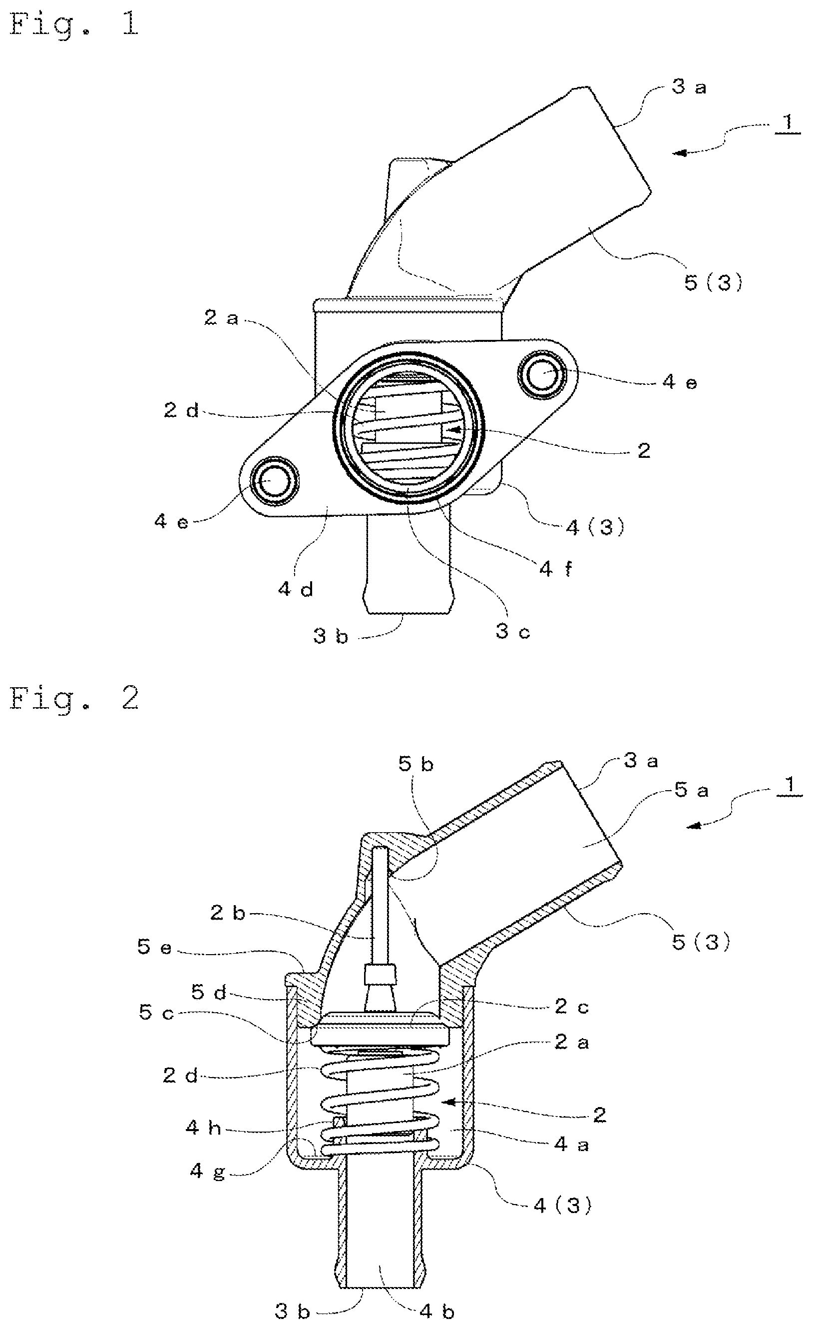
is a front view of the overall configuration of the first embodiment of the thermostat device of this invention.
shows a partial cross-sectional view of the front half of the housing in , cut away.
is a partial cross-sectional view of the left half of the housing cut away, viewed from the cutting-away direction.
is a perspective view showing the overall configuration of the thermostat device.
is a perspective view of the thermostat in the state in which the top and bottom are inverted from the state shown in .
is a partial cross-sectional view showing the flow of the coolant when the control valve is open.
is an enlarged cross-sectional view of the slope formed in the conduit of the coolant outlet.
is a partial cross-sectional view showing the main part of the second embodiment of the thermostat device of this invention.
is a partial cross-sectional view of the thermostat device in , axially rotated by 90 degrees.
is a partial cross-sectional view showing an embodiment of the flow of coolant in a conventional thermostat device.
DESCRIPTION OF EMBODIMENTS
The thermostat device of the invention will be described based on an embodiment, which is employed in an “inlet-control” type cooling system where the thermostat device is disposed at the inlet side of the coolant of an internal combustion engine.
to 7 show the first embodiment of the thermostat device 1 , of which to 5 show the overall configuration of the thermostat device 1 .
The thermostat device 1 is constructed so that a thermo-operating unit 2 , which is placed in a circulation passage for circulating coolant between the engine and radiator and controls the temperature of the coolant to be supplied to the engine, is accommodated in a housing 3 .
In other words, the thermostat device 1 is disposed at an intersection of a coolant passage from the radiator side and a bypass passage from an outlet side of the engine not passing through the radiator. The thermostat device 1 operates to appropriately control the temperature of the coolant toward an inlet of the engine, by mixing the coolant cooled at the radiator and the coolant through the bypass passage heated at the engine.
For the convenience of description, in the posture of the thermostat device 1 shown in , the upper/lower portion of the figure is simply expressed by the “upper”/“lower”.
In the embodiment, the housing 3 constituting an outer frame of the thermostat device 1 is composed of a case 4 and an inlet 5 joined and attached to the top of the case 4 , both molded of a resin material.
The inlet 5 is provided with a first inlet-side conduit 3 a (a first conduit recited in claim 1 ) having a first flow inlet 5 a formed in a cylindrical shape that receives the coolant from the radiator side, and the first inlet-side conduit 3 a is formed in an approximately 60 degrees bent state against the moving axis of a thermo-operating unit 2 described later (See ).
Further, in the case 4 , a unit accommodating space 4 a to be as an accommodation chamber, which accommodates the thermo-operating unit 2 in the central area is formed, and also a second inlet-side conduit 3 b having a cylinder-shaped second flow inlet 4 b downward from the unit accommodating space 4 a is formed; the coolant from the bypass passage is introduced to the second flow inlet 4 b.
Further, in the case 4 , an exit-side conduit 3 c (a second conduit recited in claim 1 ) is formed, having a flow outlet 4 c of the coolant to be supplied to the engine side toward the direction perpendicular to the moving axis of the thermo-operating unit 2 .
The exit-side conduit 3 c having the flow outlet 4 c of the coolant is constituted enabling it to be disposed on the upstream side of the water pump for delivering the coolant to the engine; for this purpose, a flange 4 d for directly connecting the thermostat device 1 to the water pump (not shown) side and bolt insertion holes 4 e (See ) for bolts for fastening at opposing positions by 180 degrees on the flange 4 d are formed. An annular-shaped packing 4 f to be joined with the water pump side is attached so as to surround the flow outlet 4 c of the coolant along the opening.
A cylinder-shaped thermo-element 2 a (a temperature sensing unit) incorporating a thermal expansion body (wax) that expands and contracts depending on the coolant temperature is provided in the thermo-operating unit 2 accommodated in the unit accommodating space 4 a of the housing 3 ; a piston 2 b disposed along the axis of the thermo-element 2 a operates to advance and retract from the thermo-element 2 a due to the expansion and contraction of the thermal expansion body.
The tip portion of the piston 2 b is fitted to a shaft support 5 b formed at the central upper portion inside the inlet 5 constituting the housing 3 and attached to the housing 3 .
Thus, the cylinder-shaped thermo-element 2 a operates to move along the axial direction in the unit accommodating space 4 a along with the advance and retraction of the piston 2 b ; that is, the thermo-element 2 a moves up and down in the embodiment.
In other words, the direction of the movement of the thermo-element 2 a is vertical, and the one-end side and the other-end side of the moving direction of the thermo-element 2 a in the claims are the up-side and the down-side, respectively.
A disc-shaped control valve (valve body) 2 c is attached to the upper portion of the thermo-element 2 a ; the control valve 2 c creates the valve-closed state by abutting an annular valve seat 5 c formed at the lower opening of the inlet 5 .
This means that the valve seat 5 c is formed to have a tapered shape with the diameter expanding from the one-end side toward the other-end side of the direction of movement of the thermo-element 2 a.
Further, a spring member 2 d is disposed to surround the thermo-element 2 a such that the one end thereof comes into contact with the control valve 2 c , and the other end of the spring member 2 d abuts a case inner bottom 4 g of the case 4 (See ) to surround the guide 4 h formed to erect from the case inner bottom 4 g of the case 4 .
Accordingly, the spring member 2 d applies a biasing force so as to press the disc-shaped control valve 2 c against the annular valve seat 5 c formed on the inlet 5 .
The guide 4 h supports the lower part of the thermo-element 2 a slidably. The guide 4 h is provided with a hole, a groove, or a cutout not shown, and the coolant entering the housing 3 from the second flow inlet 4 b can flow into the unit accommodating space 4 a through the hole, the groove, or the cutout of the guide 4 h.
According to thus-configured thermostat device 1 , the coolant supplied to the second flow inlet 4 b from the bypass passage side is mainly supplied to the thermo-element 2 a.
When the coolant temperature from the bypass passage side rises, the thermal expansion body incorporated in the thermo-element 2 a expands and the piston advances (protrudes).
This causes the control valve 2 c attached to the thermo-element 2 a retracts toward the second flow inlet 4 b side, resisting the biasing force of the spring member 2 d to open the valve, and the coolant via the radiator is introduced through the first flow inlet 5 a.
Resultantly, the coolant from the first flow inlet 5 a and the coolant from the second flow inlet 4 b are mixed and delivered to the water jacket of the engine through the flow outlet 4 c of the coolant. This allows controlling the coolant temperature through the water jacket of the engine to be in an appropriate state.
As shown in of the embodiment, the exit-side conduit 3 c toward the flow outlet 4 c of the coolant from the valve seat 5 c in the housing 3 is formed in a direction perpendicular to the direction of the movement axis of the thermo-element 2 a , the accommodation-chamber-side end of the exit-side conduit 3 c opposes to the side portion of the thermo-element 2 a . In addition, a slope 4 i is formed which increases the inner diameter of the exit-side conduit 3 c from the flow outlet 4 c side toward the valve seat 5 c in the exit-side conduit 3 c leading from the valve seat 5 c toward the flow outlet 4 c of the coolant.
The slope 4 i is also shown in illustrating the valve-opened state where the control valve 2 c leaves from the valve seat 5 c.
In particular, part of the slope 4 i is shown in an enlarged state in , and the accommodation-chamber-side end 4 j of the slope 4 i locates in a range from the position of the valve seat 5 c toward the one-end side of the moving direction of the thermo-element 2 a.
More specifically, inlet 5 has a brim 5 e the outer diameter of which is larger compared to the other portion; the brim 5 e is joined with the upper opening edge of the case 4 by welding, for example, whereby the case 4 and the inlet 5 are integrated as the housing 3 . Further, the inlet 5 has an annular protrusion 5 d protruding inward the case 4 from the inner peripheral edge of the brim 5 e , and the valve seat 5 c is formed at the lower end of the annular protrusion 5 d . In other words, a configuration is adopted that by providing the annular protrusion 5 d , the lower end of the valve seat 5 c is located at the same position as the upper end of the slope 4 i (accommodation-chamber-side end 4 j ) or lowered therefrom, downward in the drawing.
By setting the position of the accommodation-chamber-side end 4 j of the slope 4 i as described above, the coolant toward the flow outlet 4 c side with the opening of the control valve 2 c is led to the flow outlet 4 c side of the coolant along the slope 4 i without resistance, as shown by the arrow approaching the A direction in . This allows to provide a thermostat device 1 having little flow resistance and reduced pressure loss in the housing 3 , as recited in the paragraph of the Advantageous Effect of the Invention.
Meanwhile, in the thermostat device 1 of the first embodiment, which is provided with the second flow inlet 4 b through which the coolant from the bypass passage not passing through the radiator is introduced, upon opening the control valve 2 c , the coolant from the radiator side flows efficiently toward the flow outlet 4 c side owing to the slope 4 i . Because of this, the cooled coolant passing through the radiator is inhibited from flowing into the thermo-element 2 a side, and the temperature sensitivity (sensitivity to the temperature of the coolant circulating through the engine) is improved, whereby the hunting is inhibited.
Further, in the thermostat device 1 of the first embodiment, the housing 3 is provided with an inlet 5 having the first inlet-side conduit 3 a and the case 4 having the exit-side conduit 3 c . The inlet 5 has the annular protrusion 5 d protruding inward the case 4 , and the valve seat 5 c is formed on the tip portion of the annular protrusion 5 d . Since the position of the valve seat 5 c is lowered by the annular protrusion 5 d as described above, it is easy to locate the accommodation-chamber-side end 4 j of the slope 4 i in a range from the valve seat position to the upper side (one-end side of the moving direction of the thermo-element 2 a ).
Further, in the thermostat device 1 of the first embodiment, a brim 5 e protruding outward from the proximal end (the opposite side of the tip end) of the annular protrusion 5 d is welded to the case 4 . As described above, since the valve seat 5 c is formed on the tip end of the annular protrusion 5 d , the valve seat 5 c can be separated from the welding portion. This allows, in a state where the control valve 2 c and the valve seat 5 c are abutting on each other, to prevent the leaking of coolant from therebetween, due to the distortion of the valve seat 5 c caused by welding.
In the thermostat device 1 of the first embodiment described above, the inlet 5 and case 4 which compose the housing 3 are made of a resin material as already described; both are joined by welding preferably, but the joining method can be appropriately changeable. The inlet 5 and the case 4 can be composed using metal material.
show the thermostat device 1 of a second embodiment according to the present invention. In showing the second embodiment, members that perform the same functions as that of the thermostat device 1 of the first embodiment shown in through 7 described before are named with the same reference signs; thus, the detailed description is appropriately omitted.
In the thermostat device 1 of the second embodiment, the case 4 and the inlet 5 which compose the housing 3 are both formed of a metal material and both are joined through a packing 5 f annularly embedded in the inlet 5 .
Further, in the thermostat device 1 of the second embodiment, the other end of the spring member 2 d biasing the control valve 2 c toward the valve seat 5 c side is received by the spring receiving member 2 e ; a structure is employed that the spring receiving member 2 e is supported by an opposing pair of legs 5 g (See ) integrally formed with the inlet 5 .
Also, in the thermostat device 1 of the second embodiment, as shown in , in the exit-side conduit 3 c from the valve seat 5 c toward the flow outlet 4 c of the coolant, a slope 4 i is formed, which inclines toward the one-end side of the moving direction of the thermo-element 2 a as approaching the accommodation chamber 4 a from the flow outlet 4 c side.
Further, in this embodiment, the valve-seat 5 c side end of the slope 4 i is constructed to be continued with a taper-end portion 5 h forming the valve seat 5 c.
With the thermostat device 1 of the second embodiment, the coolant toward the flow outlet 4 c side caused by the opening of the control valve 2 c is resistlessly led toward the flow outlet 4 c side of the coolant along the slope 4 i continued with the valve seat 5 c , as shown by the arrow toward B direction in .
This allows providing a thermostat device 1 having low flow resistance and reduced pressure loss, in the housing 3 .
Accordingly, the thermostat device 1 according to the present invention including the embodiments 1 and 2 allows that the flow rate of the coolant toward the engine side from the radiator side can be secured sufficiently, and cavitation is suppressed.
This can reduce the drive power of the water pump, which flows the coolant in the circulation passage, including the engine and radiator. In addition, it can contribute to providing a thermostat device with a more down-sized outer structure.
The thermostat device 1 of the first and second embodiments described above includes a second flow inlet 4 b into which a coolant from the bypass passage is introduced. The present invention can provide similar effects if applied to a thermostat device, shown in PTL 1 as an embodiment, in which a thermostat device is provided with an inlet-side conduit to which a flow inlet for introducing the coolant cooled by the radiator is formed, an exit-side conduit to which a flow outlet of coolant to be supplied to the internal combustion engine, without including a flow inlet of the coolant from the bypass passage.
Further, the thermostat device 1 according to the present invention is described based on an embodiment where the thermostat device is employed in an inlet-control-type cooling system where the thermostat device is disposed at the inlet side of the coolant of the internal combustion engine. However, similar effects are obtainable in that pressure loss is inhibited, even when the thermostat device is employed in an outlet-control-type cooling system disposed at the outlet side of the coolant of the internal combustion engine.
INDUSTRIAL APPLICABILITY
As described above, the thermostat device according to the present invention is useful as a device for supplying coolant to an engine of an automobile and is particularly suitable for use in controlling the temperature of coolant supplied to the engine to a proper state.
REFERENCE SIGNS LIST
•
• 1 Thermostat device • 2 thermo-operating unit • 2 a thermo-element • 2 b piston • 2 c control valve (valve body) • 2 d spring member • 2 e spring receiving member • 3 housing • 3 a first inlet-side conduit (first conduit) • 3 b second inlet-side conduit • 3 c exit-side conduit (second conduit) • 4 case • 4 a unit accommodating space (accommodation chamber) • 4 b bypass passage side inlet (second flow inlet) • 4 c flow outlet • 4 d flange • 4 e bolt insertion hole • 4 f packing • 4 g case inner bottom • 4 h guide • 4 i slope • 4 j accommodation-chamber-side end • 5 inlet • 5 a radiator-side inlet (first flow inlet) • 5 b shaft support • 5 c valve seat • 5 d annular protrusion • 5 e brim • 5 f packing • 5 g leg • 5 h taper-end portion.
Figures (8)
Citations
This patent cites (21)
- US3207437
- US3472453
- US3979105
- US6045051
- US2006/0163373
- US2011/0095091
- US2012/0319028
- US2016/0356203
- US2018/0017155
- US2020/0123962
- US2020/0333811
- US102105728
- US3431767
- US2000-073880
- US2005090726
- US2005-330920
- US2011-231856
- US2012-112271
- US2012184693
- US2010/004606
- US2019-066759