Abstract
A shovel ( 100 ) according to an embodiment of the present invention includes a lower travelling body ( 1 ), an upper pivot body ( 3 ) pivotably mounted to the lower travelling body ( 1 ), an excavation attachment (AT) provided to the upper pivot body ( 3 ), a plurality of actuators that operate the excavation attachment (AT), an operation device ( 26 ) provided to the upper pivot body ( 3 ), and a controller ( 30 ) configured to, in response to an operation of the operation device ( 26 ) in a first direction, operate the plurality of actuators to move a predetermined portion of the excavation attachment (AT) based on position information. The controller ( 30 ) operates the plurality of actuators in a first control mode and a second control mode based on the position information.
Claims (18)
1. A shovel, comprising: a lower travelling body; an upper pivot body pivotably mounted to the lower travelling body; an attachment provided to the upper pivot body; a plurality of actuators that operate the attachment; an operation device provided to the upper pivot body; and a hardware processor configured to, in response to an operation of the operation device in a predetermined direction, operate the plurality of actuators to move a predetermined portion of the attachment based on position information, wherein the hardware processor is configured to operate the plurality of actuators in a first control mode and a second control mode by switching between the first control mode and the second control mode based on the position information while moving the predetermined portion of the attachment along a predetermined trajectory set in a target of excavation, and the hardware processor is configured to operate the plurality of actuators in the first control mode when an angle of the predetermined trajectory with respect to a reference plane is less than a predetermined angle, and to operate the plurality of actuators in the second control mode when the angle of the predetermined trajectory with respect to the reference plane is greater than or equal to the predetermined angle.
Show 17 dependent claims
2. The shovel as claimed in claim 1 , wherein a movement speed of the predetermined portion relative to an operation amount of the operation device is greater in the first control mode than in the second control mode.
3. The shovel as claimed in claim 1 , wherein the hardware processor is configured to operate the plurality of actuators in the first control mode when a distance between an embedded object and the predetermined portion is greater than a predetermined distance, and to operate the plurality of actuators in the second control mode when the distance between the embedded object and the predetermined portion is smaller than the predetermined distance.
4. The shovel as claimed in claim 1 , wherein the hardware processor is configured to operate the plurality of actuators in the second control mode in a portion of the predetermined trajectory which includes a point where a direction of the predetermined trajectory changes by greater than or equal to another predetermined angle.
5. The shovel as claimed in claim 1 , wherein the hardware processor is configured to operate the plurality of actuators in the second control mode when an object is recognized around the shovel based on an output of a space recognition device provided to the upper pivot body.
6. The shovel as claimed in claim 1 , wherein the hardware processor is configured to operate the plurality of actuators in the first control mode when the predetermined trajectory is within a predetermined distance range from the shovel and the angle of the predetermined trajectory with respect to the reference plane is within a predetermined angle range, and to operate the plurality of actuators in the second control mode otherwise.
7. The shovel as claimed in claim 1 , further comprising: a posture detection device that detects a posture of the attachment, wherein the hardware processor is configured to detect the posture of the attachment based on a detected value from the posture detection device and to determine whether to operate the plurality of actuators in the first control mode or the second control mode based on the posture of the attachment.
8. The shovel as claimed in claim 1 , wherein the hardware processor is configured to switch between the first control mode and the second control mode depending on a portion of the target of excavation.
9. The shovel as claimed in claim 1 , wherein the hardware processor is configured to switch between the first control mode and the second control mode depending on a change of the position information along the predetermined trajectory.
10. The shovel as claimed in claim 1 , wherein the attachment includes a boom and an arm provided to the upper pivot body, and the hardware processor is configured to cause the arm to operate depending on the boom.
11. The shovel as claimed in claim 10 , wherein the hardware processor is configured to cause the arm to operate along the predetermined trajectory depending on the boom.
12. The shovel as claimed in claim 10 , wherein the hardware processor is configured to switch between a first operation of causing the arm to operate depending on the boom and a second operation of causing the boom to operate depending on the arm.
13. The shovel as claimed in claim 1 , wherein the hardware processor is configured to switch between the first control mode and the second control mode while moving the predetermined portion of the attachment along the predetermined trajectory set in the target of excavation during an excavation.
14. The shovel as claimed in claim 13 , wherein the predetermined trajectory is preset in the target of excavation.
15. The shovel as claimed in claim 1 , wherein the hardware processor is configured to operate the plurality of actuators in the first control mode and the second control mode by automatically switching between the first control mode and the second control mode based on the position information while autonomously moving the predetermined portion of the attachment along the predetermined trajectory set in the target of excavation.
16. The shovel as claimed in claim 1 , wherein the hardware processor is configured to move the predetermined portion of the attachment along the predetermined trajectory set in the target of excavation by autonomously moving at least one of the plurality of actuators in response to the operation device being operated to move another one of the plurality of actuators.
17. The shovel as claimed in claim 1 , wherein the attachment includes a boom mounted on the upper pivot body, an arm attached to a tip of the boom, and a bucket attached to a tip of the arm, the plurality of actuators include a boom cylinder configured to drive the boom, an arm cylinder configured to drive the arm, and a bucket cylinder configured to drive the bucket, and the hardware processor is configured to operate the arm cylinder according as the operation device is operated to operate the arm cylinder, and autonomously operate at least one of the boom cylinder or the bucket cylinder according to an operation of the arm cylinder, in the first control mode, and operate the boom cylinder according as the operation device is operated to operate the boom cylinder, and autonomously operate at least one of the arm cylinder or the bucket cylinder according to an operation of the boom cylinder, in the second control mode.
18. The shovel as claimed in claim 1 , wherein the predetermined trajectory includes a first trajectory portion, a second trajectory portion continuing from the first trajectory portion, and a third trajectory portion continuing from the second trajectory portion, and the hardware processor is configured to operate the plurality of actuators in the first control mode in the first trajectory portion, switch the first control mode to the second control mode in response to determining that a distance between the predetermined portion of the attachment and a boundary point between the first trajectory portion and the second trajectory portion along the predetermined trajectory is less than a first predetermined distance, when an angle of the second trajectory portion with respect to the reference plane is greater than or equal to the predetermined angle, and operate the plurality of actuators in the second control mode in the second trajectory portion, and switch the second control mode to the first control mode in response to determining that a distance between the predetermined portion of the attachment and a boundary point between the second trajectory portion and the third trajectory portion along the predetermined trajectory is less than a second predetermined distance, when an angle of the third trajectory portion with respect to the reference plane is less than the predetermined angle, and operate the plurality of actuators in the first control mode in the third trajectory portion.
Full Description
Show full text →
CROSS-REFERENCE TO RELATED APPLICATIONS
The present application is a continuation application of International Application No. PCT/JP2019/013713 filed on Mar. 28, 2019, which claims priority to Japanese Patent Application No. 2018-068048 filed on Mar. 30, 2018. The contents of these applications are incorporated herein by reference in their entirety.
BACKGROUND
Technical Field
The present disclosure relates to shovels as excavators.
Description of the Related Art
Conventionally, a shovel having a leveling excavation control mode where a blade edge of a bucket is moved along a design plane is known.
SUMMARY
However, the leveling excavation control mode is control to adjust the relative speed of the bucket blade edge with respect to the design plane depending on the distance between the bucket blade edge and the design plane, and there is a risk that the movement speed of the bucket blade edge moving along the design plane while retaining the distance between the bucket blade edge and the design plane cannot be appropriately controlled.
Therefore, it is desirable to provide a shovel that can control the movement of a predetermined portion of an attachment along a predetermined trajectory more appropriately.
A shovel according to an embodiment of the present invention includes a lower travelling body, an upper pivot body pivotably mounted to the lower travelling body, an attachment provided to the upper pivot body, a plurality of actuators that operate the attachment, an operation device provided to the upper pivot body, and a controller configured to, in response to an operation of the operation device in a first direction, operate the plurality of actuators to move a predetermined portion of the attachment based on position information, wherein the controller operates the plurality of the actuators in a first control mode and a second control mode based on the position information.
According to the above-stated solution, a shovel that can control the movement of a predetermined portion of an attachment along a predetermined trajectory more appropriately is provided.
BRIEF DESCRIPTION OF THE DRAWINGS
is a side view of a shovel according to an embodiment of the present invention;
is a top view of the shovel of ;
is a diagram for illustrating an exemplary arrangement of a hydraulic system mounted to the shovel in ;
A is a view of a portion of a hydraulic system related to operations of an arm cylinder;
B is a view of a portion of a hydraulic system related to operations of a boom cylinder;
C is a view of a portion of a hydraulic system related to operation of a bucket cylinder;
D is a view of a portion of a hydraulic system related to operation of a pivot hydraulic motor;
is a functional block diagram of a controller;
is a diagram for illustrating one exemplary control mode switch operation;
A is a diagram for illustrating another exemplary control mode switch operation;
B is a diagram for illustrating another exemplary control mode switch operation;
is a diagram for illustrating a still further exemplary control mode switch operation;
A is a diagram for illustrating a still further exemplary control mode switch operation;
B is a diagram for illustrating a still further exemplary control mode switch operation;
is a block diagram for illustrating one exemplary relationship of functional elements related to execution of semi-automatic control at a controller;
is a block diagram for illustrating one exemplary arrangement of functional elements for calculating various command values; and
is a diagram for illustrating one exemplary arrangement of an electric operation system.
DETAILED DESCRIPTION
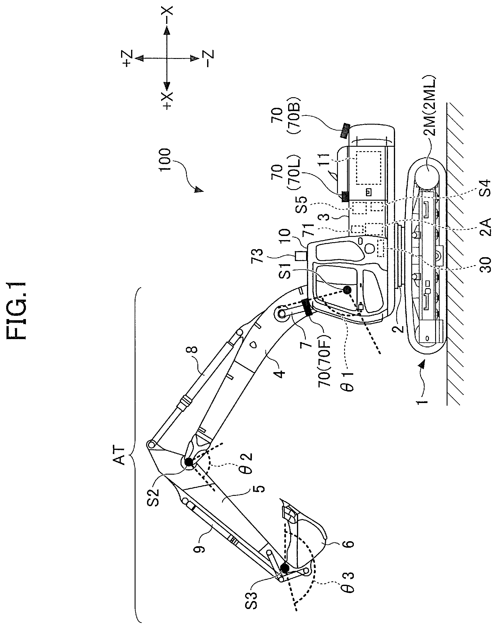
First, a shovel 100 as an excavator according to an embodiment of the present invention is described with reference to . is a side view of the shovel 100 , and is a top view of the shovel 100 .
In this embodiment, a lower travelling body 1 of the shovel 100 includes a crawler 1 C. The crawler 1 C is driven by a travelling hydraulic motor 2 M as a travelling actuator mounted to the lower travelling body 1 . Specifically, the crawler 1 C includes a left crawler 1 CL and a right crawler 1 CR. The left crawler 1 CL is driven by a left travelling hydraulic motor 2 ML, and the right crawler 1 CR is driven by a right travelling hydraulic motor 2 MR.
An upper swiveling body 3 is pivotably mounted to the lower travelling body 1 through a pivot mechanism 2 . The pivot mechanism 2 is driven by a pivot hydraulic motor 2 A as a pivot actuator mounted to the upper pivot body 3 . However, the pivot actuator may be a pivot motor generator as an electric actuator.
A boom 4 is mounted to the upper pivot body 3 . An arm 5 is attached to the tip of the boom 4 , and a bucket 6 as an end attachment is attached to the tip of the arm 5 . The boom 4 , the arm 5 , and the bucket 6 compose an excavation attachment AT, which is one exemplary attachment. The boom 4 is driven by a boom cylinder 7 , the arm 5 is driven by an arm cylinder 8 , and the bucket 6 is driven by a bucket cylinder 9 . The boom cylinder 7 , the arm cylinder 8 , and the bucket cylinder 9 compose an attachment actuator.
The boom 4 is rotatably supported up and down with respect to the upper pivot body 3 . Then, a boom angle sensor S 1 is mounted to the boom 4 . The boom angle sensor S 1 can detect the boom angle θ 1 , which is the rotation angle of the boom 4 . The boom angle θ 1 may be, for example, the raised angle from the state where the boom 4 is most lowered. Therefore, the boom angle θ 1 is maximized when the boom 4 is most raised.
The arm 5 is pivotally supported relative to the boom 4 . Then, an arm angle sensor S 2 is mounted to the arm 5 . The arm angle sensor S 2 can detect the arm angle θ 2 , which is the rotation angle of the arm 5 . The arm angle θ 2 may be, for example, an opening angle from the state where the arm 5 is most closed. Therefore, the arm angle θ 2 is maximized when the arm 5 is most opened.
The bucket 6 is rotatably supported relative to the arm 5 . Then, a bucket angle sensor S 3 is mounted to the bucket 6 . The bucket angle sensor S 3 can detect the bucket angle θ 3 , which is the rotation angle of the bucket 6 . The bucket angle θ 3 is the opening angle from the most closed state of the bucket 6 . Therefore, the bucket angle θ 3 is maximized when the bucket 6 is most opened.
In the embodiment of , the boom angle sensor S 1 , the arm angle sensor S 2 , and the bucket angle sensor S 3 each includes a combination of an acceleration sensor and a gyro sensor. However, it may be composed of only an acceleration sensor. Also, the boom angle sensor S 1 may be a stroke sensor, a rotary encoder, a potentiometer, an inertia measuring device, or the like mounted to the boom cylinder 7 . The same applies to the arm angle sensor S 2 and the bucket angle sensor S 3 .
A cabin 10 is provided to the upper pivot body 3 as an operator's cab, and a power source such as an engine 11 is mounted therein. Also, a space recognition device 70 , an orientation detection device 71 , a positioning device 73 , a body tilt sensor S 4 , and a pivot angular velocity sensor S 5 are mounted to the upper pivot body 3 . An operation device 26 , a controller 30 , an information input device 72 , a display device D 1 , a sound output device D 2 , or the like are mounted in the cabin 10 . For convenience, it is assumed in the specification that the side where the excavation attachment AT is mounted in the upper pivot body 3 is the front side and the side where a counterweight is mounted is the rear side.
The space recognition device 70 is configured to recognize an object existing in the three-dimensional space around the shovel 100 . Also, the space recognition device 70 may be configured to calculate the distance from the space recognition device 70 or the shovel 100 to the recognized object. The space recognition device 70 may include, for example, an ultrasonic sensor, a millimeter wave radar, a monocular camera, a stereo camera, a LIDAR, a distance image sensor, an infrared sensor, and the like. In this embodiment, the space recognition device 70 includes a front sensor 70 F mounted to the top end of the front surface of the cabin 10 , a rear sensor 70 B mounted to the rear end of the top surface of the upper pivot body 3 , a left sensor 70 L mounted to the left end of the top surface of the upper pivot body 3 , and a right sensor 70 R mounted to the right end of the top surface of the upper pivot body 3 . An upper sensor for recognizing an object existing in the space above the upper pivot body 3 may be attached to the shovel 100 .
The orientation detection device 71 is configured to detect information regarding the relative relationship between the orientation of the upper pivot body 3 and the orientation of the lower travelling body 1 . The orientation detection device 71 may be composed of, for example, a combination of a geomagnetic sensor mounted to the lower travelling body 1 and a geomagnetic sensor mounted to the upper pivot body 3 . Alternatively, the orientation detection device 71 may be composed of, for example, a combination of a GNSS receiver mounted to the lower travelling body 1 and a GNSS receiver mounted to the upper pivot body 3 . The orientation detection device 71 may be a rotary encoder, a rotary position sensor, or the like. In the arrangement in which the upper pivot body 3 is pivotably driven by a pivot electric generator, the orientation detection device 71 may be composed of a resolver. The orientation detection device 71 may be mounted, for example, to a center joint disposed in connection with the pivot mechanism 2 for implementing the relative rotation between the lower travelling body 1 and the upper pivot body 3 . The orientation detection device 71 may be composed of a camera mounted to the upper pivot body 3 . In this case, the orientation detection device 71 performs known image processing on an image (input image) captured by the camera mounted to the upper pivot body 3 to detect an image of the lower travelling body 1 included in the input image. Then, the orientation detection device 71 identifies the longitudinal direction of the lower travelling body 1 by detecting the image of the lower travelling body 1 using a known image recognition technique. Then, an angle formed between the direction of the front-rear axis of the upper pivot body 3 and the longitudinal direction of the lower travelling body 1 is derived. The direction of the front-rear axis of the upper pivot body 3 can be derived from the installation position of the camera. In particular, since the crawler 1 C protrudes from the upper pivot body 3 , the orientation detection device 71 can determine the longitudinal direction of the lower travelling body 1 by detecting an image of the crawler 1 C. In this case, the orientation detection device 71 may be integrated with the controller 30 .
The information input device 72 is configured so that an operator of the shovel can input information to the controller 30 . In this embodiment, the information input device 72 is a switch panel located adjacent to a display unit of the display device D 1 . However, the information input device 72 may be a touch panel disposed on the display portion of the display device D 1 or a sound input device such as a microphone disposed in the cabin 10 .
The positioning device 73 is configured to measure the position of the upper pivot body 3 . In this embodiment, the positioning device 73 is a GNSS receiver to detect the position of the upper pivot body 3 and output a detected value to the controller 30 . The positioning device 73 may be a GNSS compass. In this case, the positioning device 73 can detect the position and orientation of the upper pivot body 3 .
The body tilt sensor S 4 detects the tilt of the upper pivot body 3 relative to a predetermined plane. In this embodiment, the body tilt sensor S 4 is an acceleration sensor to detect a tilt angle about the front-rear axis of the upper pivot body 3 with respect to the horizontal plane and a tilt angle about the right-left axis. The front-rear axis and the left-right axis of the upper pivot body 3 pass through a shovel center point, which is one point on the pivot axis of the shovel 100 perpendicular to each other, for example.
The pivot angular velocity sensor S 5 detects the pivot angular velocity of the upper pivot body 3 . In this embodiment, it is a gyro sensor. It may be a resolver, a rotary encoder, or the like. The pivot angular velocity sensor S 5 may detect the pivot velocity. The pivot velocity may be calculated from the pivot angular velocity.
Hereinafter, at least one of the boom angle sensor S 1 , the arm angle sensor S 2 , the bucket angle sensor S 3 , the body tilt sensor S 4 , and the pivot angular velocity sensor S 5 is also referred to as a posture detection device. The posture of an excavation attachment AT may be detected, for example, based on respective outputs of the boom angle sensor S 1 , the arm angle sensor S 2 and the bucket angle sensor S 3 .
The display device D 1 is a device for displaying information. In this embodiment, the display device D 1 is a liquid crystal display installed in cabin 10 . However, the display device D 1 may be a display of a portable terminal such as a smartphone.
The sound output device D 2 is a device to output sound. The sound output device D 2 includes at least one of a device for outputting sound to an operator in the cabin 10 and a device for outputting sound to a worker outside the cabin 10 . It may be a speaker of a portable terminal.
The operation device 26 is a device used by an operator for operations of an actuator.
The controller 30 is a controller for controlling the shovel 100 . In this embodiment, the controller 30 is composed of a computer including a CPU, a volatile storage device, a non-volatile storage device, and the like. Then, the controller 30 reads programs corresponding to respective functions from the non-volatile storage device and loads the programs to the volatile storage device to cause the CPU to perform the corresponding operations. The functions may include, for example, a machine guidance function for guiding operator's manual operations of the shovel 100 and a machine control function for supporting the operator's manual operations of the shovel 100 or causing the shovel 100 to operate automatically or autonomously.
Next, an exemplary arrangement of a hydraulic system mounted to the shovel 100 is described with reference to . is a diagram for illustrating an exemplary arrangement of the hydraulic system mounted to the shovel 100 . shows a mechanical power transmission system, a hydraulic oil line, a pilot line and an electric control system with a double line, a solid line, a dashed line and a dotted line, respectively.
The hydraulic system of the shovel 100 mainly includes an engine 11 , a regulator 13 , a main pump 14 , a pilot pump 15 , a control valve 17 , an operation device 26 , a discharge pressure sensor 28 , an operation pressure sensor 29 , a controller 30 , and the like.
In , the hydraulic system is configured to circulate the hydraulic oil from the main pump 14 driven by the engine 11 to the hydraulic oil tank via a center bypass line 40 or a parallel line 42 .
The engine 11 is a driving source of the shovel 100 . In this embodiment, the engine 11 may be, for example, a diesel engine for operating to retain a predetermined number of rotations. The output shaft of the engine 11 is coupled to the input shaft of the main pump 14 and the pilot pump 15 .
The main pump 14 is configured to supply the hydraulic oil to the control valve 17 via a hydraulic oil line. In this embodiment, the main pump 14 is a swashplate variable capacity type of hydraulic pump.
The regulator 13 is configured to control the discharge amount of the main pump 14 . In this embodiment, the regulator 13 controls the discharge amount of the main pump 14 by adjusting the swashplate tilt angle of the main pump 14 in response to a control command from the controller 30 .
The pilot pump 15 is configured to supply the hydraulic oil to a hydraulic control device including the operation device 26 through a pilot line. In this embodiment, the pilot pump 15 is a fixed capacity type of hydraulic pump. However, the pilot pump 15 may be omitted. In this case, the function performed by the pilot pump 15 may be implemented by the main pump 14 . Namely, the main pump 14 may include a function of supplying the hydraulic oil to the operation device 26 or the like after reduction in the pressure of the hydraulic oil with a throttle or the like separately from a function of supplying the hydraulic oil to the control valve 17 .
The control valve 17 is a hydraulic controller for controlling the hydraulic system in the shovel 100 . In this embodiment, the control valve 17 includes control valves 171 to 176 . The control valve 175 includes control valve 175 L and control valve 175 R, and the control valve 176 includes control valves 176 L and 1756 . The control valve 17 is configured to selectively supply the hydraulic oil discharged by the main pump 14 to one or more hydraulic actuators through the control valves 171 to 176 . The control valves 171 to 176 may control, for example, the flow amount of the hydraulic oil flowing from the main pump 14 to the hydraulic actuator and the flow amount of the hydraulic oil flowing from the hydraulic actuator to the hydraulic oil tank. The hydraulic actuator include the boom cylinder 7 , the arm cylinder 8 , the bucket cylinder 9 , the left travelling hydraulic motor 2 ML, the right travelling hydraulic motor 2 MR, and the pivot hydraulic motor 2 A.
The operation device 26 is a device used by an operator to operate an actuator. The operation device 26 may include, for example, an operation lever and an operation pedal. The actuator includes at least one of a hydraulic actuator and an electric actuator. In this embodiment, the operation device 26 is configured to supply the hydraulic oil discharged by the pilot pump 15 to a pilot port of the corresponding control valve in the control valve 17 via a pilot line. The pressure (pilot pressure) of the hydraulic oil supplied to each of the pilot ports is the pressure corresponding to the operation direction and the operation amount of the operation device 26 corresponding to each of the hydraulic actuators. However, the operation device 26 may be of an electric control type rather than a pilot pressure type as described above. In this case, the control valve in the control valve 17 may be a solenoid spool valve.
The discharge pressure sensor 28 is configured to detect the discharge pressure of the main pump 14 . In this embodiment, the discharge pressure sensor 28 outputs a detected value to the controller 30 .
The operation pressure sensor 29 is configured to detect operational contents of the operation device 26 by an operator. In this embodiment, the operation pressure sensor 29 detects the operation direction and the operation amount of the operation device 26 corresponding to each of the actuators in the form of pressure (operation pressure) and outputs the detected value to the controller 30 . The operational contents of the operation device 26 may be detected using other sensors other than the operation pressure sensor.
The main pump 14 includes a left main pump 14 L and a right main pump 14 R. Then, the left main pump 14 L circulates the hydraulic oil to the hydraulic oil tank through the left center bypass line 40 L or the left parallel line 42 L, and the right main pump 14 R circulates the hydraulic oil to the hydraulic oil tank through the right center bypass line 40 R or the right parallel line 42 R.
The left center bypass line 40 L is a hydraulic oil line for passing through the control valves 171 , 173 , 175 L and 176 L disposed in the control valve 17 . The right center bypass line 40 R is a hydraulic oil line for passing through the control valves 172 , 174 , 175 R and 176 R disposed in the control valve 17 .
The control valve 171 is a spool valve for feeding the hydraulic oil discharged by the left main pump 14 L to the left travelling hydraulic motor 2 ML and switching the flow of the hydraulic oil to discharge the hydraulic oil discharged by the left travelling hydraulic motor 2 ML to the hydraulic oil tank.
The control valve 172 is a spool valve for feeding the hydraulic oil discharged by the right main pump 14 R to the right travelling hydraulic motor 2 MR and switching the flow of the hydraulic oil to discharge the hydraulic oil discharged by the right travelling hydraulic motor 2 MR to the hydraulic oil tank.
The control valve 173 is a spool valve for supplying the hydraulic oil discharged by the left main pump 14 L to the pivot hydraulic motor 2 A and switching the flow of the hydraulic oil to discharge the hydraulic oil discharged by the pivot hydraulic motor 2 A to the hydraulic oil tank.
The control valve 174 is a spool valve for feeding the hydraulic oil discharged by the right main pump 14 R to the bucket cylinder 9 and switching the flow of the hydraulic oil to discharge the hydraulic oil in the bucket cylinder 9 to the hydraulic oil tank.
The control valve 175 L is a spool valve for switching the flow of the hydraulic oil to supply the hydraulic oil discharged by the left main pump 14 L to the boom cylinder 7 . The control valve 175 R is a spool valve for feeding the hydraulic oil discharged by the right main pump 14 R to the boom cylinder 7 and switching the flow of the hydraulic oil to discharge the hydraulic oil in the boom cylinder 7 to the hydraulic oil tank.
The control valve 176 L is a spool valve for feeding the hydraulic oil discharged by the left main pump 14 L to the arm cylinder 8 and switching the flow of the hydraulic oil to discharge the hydraulic oil in the arm cylinder 8 to the hydraulic oil tank.
The control valve 176 R is a spool valve for feeding the hydraulic oil discharged by the right main pump 14 R to the arm cylinder 8 and switching the flow of the hydraulic oil to discharge the hydraulic oil in the arm cylinder 8 to the hydraulic oil tank.
The left parallel line 42 L is a hydraulic oil line parallel to the left center bypass line 40 L. If the flow of the hydraulic oil passing through the left center bypass line 40 L is limited or interrupted by any of the control valves 171 , 173 and 175 L, the left parallel line 42 L can supply the hydraulic oil to a downstream control valve. The right parallel line 42 R is a hydraulic oil line parallel to the right center bypass line 40 R. If the flow of the hydraulic oil passing through the right center bypass line 40 R is limited or interrupted by any of the control valves 172 , 174 and 175 R, the right parallel line 42 R can supply the hydraulic oil to a downstream control valve.
The regulator 13 includes a left regulator 13 L and a right regulator 13 R. The left regulator 13 L controls the discharge amount of the left main pump 14 L by adjusting the swashplate tilt angle of the left main pump 14 L in accordance with increasing the discharge pressure of the left main pump 14 L. Specifically, the left regulator 13 L adjusts the swashplate tilt angle of the left main pump 14 L in accordance with increasing the discharge pressure of the left main pump 14 L to reduce the discharge amount, for example. The same applies to the right regulator 13 R. This is to avoid the absorbed horsepower of the main pump 14 , which is expressed as the product of the discharge pressure and the discharge amount, exceeding the output horsepower of the engine 11 .
The operation device 26 includes a left operation lever 26 L, a right operation lever 26 R and a travelling lever 26 D. The travelling lever 26 D includes a left travelling lever 26 DL and a right travelling lever 26 DR.
The left operation lever 26 L is used for the rotation operation and the operation of the arm 5 . The left operation lever 26 L, when it is operated in a forward-backward direction, utilizes the hydraulic oil discharged by the pilot pump 15 to introduce the control pressure corresponding to the lever operation amount into the pilot port of the control valve 176 . Also, when it is operated in the right-left direction, the left operation lever 26 L utilizes the hydraulic oil discharged by the pilot pump 15 to introduce the control pressure corresponding to the lever operation amount into the pilot port of the control valve 173 .
Specifically, when it is operated in the arm closing direction, the left operation lever 26 L introduces the hydraulic oil to the right pilot port of the control valve 176 L and introduces the hydraulic oil to the left pilot port of the control valve 176 R. Also, the left operation lever 26 L, when it is operated in the arm opening direction, introduces the hydraulic oil to the left pilot port of the control valve 176 L and introduces the hydraulic oil to the right pilot port of the control valve 176 R. Also, when it is operated in the left pivot direction, the left operation lever 26 L introduces the hydraulic oil to the left pilot port of the control valve 173 and when it is operated in the right pivot direction, introduces the hydraulic oil to the right pilot port of the control valve 173 .
The right operation lever 26 R is used to operate the boom 4 and the bucket 6 . The right operation lever 26 R, when it is operated in the forward-backward direction, utilizes the hydraulic oil discharged by the pilot pump 15 to introduce the control pressure corresponding to the lever operation amount into the pilot port of the control valve 175 . Also, when it is operated in the right-left direction, the right operation lever 26 R utilizes the hydraulic oil discharged by the pilot pump 15 to introduce the control pressure corresponding to the lever operation amount into the pilot port of the control valve 174 .
Specifically, the right operation lever 26 R, when it is operated in the boom down direction, introduces the hydraulic oil to the left pilot port of the control valve 175 R. Also, the right operation lever 26 R, when it is operated in the boom up direction, introduces the hydraulic oil to the right pilot port of the control valve 175 L and introduces the hydraulic oil to the left pilot port of the control valve 175 R. Also, the right operation lever 26 R, when it is operated in the bucket closing direction, introduces the hydraulic oil to the right pilot port of the control valve 174 and when it is operated in the bucket opening direction, introduces the hydraulic oil to the left pilot port of the control valve 174 .
The travelling lever 26 D is used to operate the crawler 1 C. Specifically, the left travelling lever 26 DL is used to operate the left crawler 1 CL. It may be configured to interlock with the left travelling pedal. The left travelling lever 26 DL, when it is operated in the forward-backward direction, utilizes the hydraulic oil discharged by the pilot pump 15 to introduce the control pressure corresponding to the lever operation amount into the pilot port of the control valve 171 . The right travelling lever 26 DR is used to operate the right crawler 1 CR. It may be configured to interlock with the right travelling pedal. The right travelling lever 26 DR, when it is operated in the forward-backward direction, utilizes the hydraulic oil discharged by the pilot pump 15 to introduce the control pressure corresponding to the lever operation amount into the pilot port of the control valve 172 .
The discharge pressure sensor 28 includes a discharge pressure sensor 28 L and a discharge pressure sensor 28 R. The discharge pressure sensor 28 L detects the discharge pressure of the left main pump 14 L and outputs a detected value to the controller 30 . The same applies to the discharge pressure sensor 28 R.
The operation pressure sensor 29 includes operation pressure sensors 29 LA, 29 LB, 29 RA, 29 RB, 29 DL and 29 DR. The operation pressure sensor 29 LA detects operational contents of the left operation lever 26 L in the forward-backward direction by the operator in the form of pressure and outputs a detected value to the controller 30 . The operational contents may be, for example, the lever operation direction, the lever operation amount (lever operation angle) or the like.
Similarly, the operation pressure sensor 29 LB detects operational contents of the left operation lever 26 L in the left-right direction by the operator in the form of pressure and outputs a detected value to the controller 30 . The operation pressure sensor 29 RA detects operational contents of the right operation lever 26 R in the forward-backward direction by the operator in the form of pressure and outputs a detected value to the controller 30 . The operation pressure sensor 29 RB detects operational contents of the right operation lever 26 R in the left-right direction by the operator in the form of pressure and outputs a detected value to the controller 30 . The operation pressure sensor 29 DL detects operational contents of the left running lever 26 DL in the forward-backward direction by the operator in the form of pressure and outputs a detected value to the controller 30 . The operation pressure sensor 29 DR detects operational contents of the right travelling lever 26 DR in the forward-backward direction by the operator in the form of pressure and outputs a detected value to the controller 30 .
The controller 30 receives an output of the operation pressure sensor 29 and outputs a control command to the regulator 13 as needed to change the discharge amount of the main pump 14 . Also, the controller 30 receives an output of the control pressure sensor 19 provided in the upstream of the throttle 1 and outputs a control command to the regulator 13 as necessary to change the discharge amount of the main pump 14 . The throttle 18 includes a left throttle 18 L and a right throttle 18 R, and the control pressure sensor 19 includes a left control pressure sensor 19 L and a right control pressure sensor 19 R.
In the left center bypass line 40 L, a left throttle 18 L is disposed between the control valve 176 L, which is in the most downstream, and the hydraulic oil tank. Therefore, the flow of the hydraulic oil discharged by the left main pump 14 L is limited by the left diaphragm 18 L. Then, the left throttle 18 L generates a control pressure for controlling the left regulator 13 L. The left control pressure sensor 19 L is a sensor for detecting the control pressure and outputting a detected value to the controller 30 . The controller 30 controls the discharge amount of the left main pump 14 L by adjusting the swashplate tilt angle of the left main pump 14 L depending on the control pressure. The controller 30 decreases the discharge amount of the left main pump 14 L as the control pressure is higher, and increases the discharge amount of the left main pump 14 L as the control pressure is lower. The discharge amount of the right main pump 14 R is similarly controlled.
Specifically, if none of the hydraulic actuators in the shovel 100 is in the non-operated standby state as shown in , the hydraulic oil discharged by the left main pump 14 L passes through the left center bypass line 40 L toward the left throttle 18 L. Then, the flow of the hydraulic oil discharged by the left main pump 14 L increases the control pressure generated in the upstream of the left throttle 18 L. As a result, the controller 30 reduces the discharge amount of the left main pump 14 L to an allowable minimum discharge amount and suppresses the pressure loss (pumping loss) at passage of the discharged hydraulic oil through the left center bypass line 40 L. On the other hand, if any of the hydraulic actuators is operated, the hydraulic oil discharged by the left main pump 14 L flows into a to-be-operated hydraulic actuator through a control valve corresponding to the to-be-operated hydraulic actuator. Then, the flow of the hydraulic oil discharged by the left main pump 14 L decreases or disappears the amount reaching the left throttle 18 L, thereby lowering the control pressure generated in the upstream of the left throttle 18 L. As a result, the controller 30 increases the discharge amount of the left main pump 14 L to circulate a sufficient amount of the hydraulic oil to the to-be-operated hydraulic actuator to ensure driving of the to-be-operated hydraulic actuator. Note that the controller 30 controls the discharge amount of the right main pump 14 R in the same manner.
According to the above-stated arrangement, the hydraulic system of can reduce wasted energy consumption at the main pump 14 in the standby state. The wasteful energy consumption includes a pumping loss caused by the hydraulic oil discharged by the main pump 14 in the center bypass line 40 . Also, the hydraulic system of , when the hydraulic actuator is operated, ensures that a necessary and sufficient amount of the hydraulic oil can be supplied from the main pump 14 to the to-be-operated hydraulic actuator.
Next, an arrangement of the controller 30 causing an actuator to operate by means of a machine control function is described with reference to A to 4 D . A to 4 D are views of portions of a hydraulic system. Specifically, A is a view of a portion of the hydraulic system related to operations of the arm cylinder 8 , and B is a view of a portion of the hydraulic system related to operations of the boom cylinder 7 . C is a view of a portion of the hydraulic system related to operations of the bucket cylinder 9 , and D is a view of a portion of the hydraulic system related to operations of the pivot hydraulic motor 2 A.
As shown in A to 4 D , the hydraulic system includes a proportional valve 31 and a shuttle valve 32 . The proportional valve 31 includes proportional valves 31 AL to 31 DL and 31 AR to 31 DR, and the shuttle valve 32 includes shuttle valves 32 AL to 32 DL and 32 AR to 32 DR.
The proportional valve 31 functions as a control valve for machine control. The proportional valve 31 is disposed in a conduit for coupling the pilot pump 15 with the shuttle valve 32 and is configured to change the flow area of the conduit. In this embodiment, the proportional valve 31 operates in response to a control command fed from the controller 30 . Thus, the controller 30 can supply the hydraulic oil discharged by the pilot pump 15 to the pilot port of the corresponding control valve in the control valve 17 via the proportional valve 31 and the shuttle valve 32 , regardless of operator's operations of the operation device 26 .
The shuttle valve 32 includes two inlet ports and one outlet port. One of the two inlet ports is coupled to the operation device 26 , and the other is coupled to the proportional valve 31 . The outlet port is coupled to a pilot port of the corresponding control valve in control valve 17 . Thus, the shuttle valve 32 can cause the higher of the pilot pressure generated by the operation device 26 and the pilot pressure generated by the proportional valve 31 to be applied to the corresponding pilot port of the control valve.
According to this arrangement, even if no operation is performed on the particular operation device 26 , the controller 30 can operate a hydraulic actuator corresponding to the particular operation device 26 .
For example, as shown in A , the left operation lever 26 L is used to operate the arm 5 . Specifically, the left operation lever 26 L utilizes the hydraulic oil discharged by the pilot pump 15 to apply the pilot pressure corresponding to operations in the forward-backward direction to the pilot port of the control valve 176 . More specifically, the left operation lever 26 L, if it is operated in the arm closing direction (backward direction), applies the pilot pressure corresponding to the operation amount to the right pilot port of the control valve 176 L and the left pilot port of the control valve 176 R. Also, if the left operation lever 26 L is operated in the arm opening direction (forward direction), the left operation lever 26 L applies the pilot pressure corresponding to the operation amount to the left pilot port of the control valve 176 L and the right pilot port of the control valve 176 R.
A switch NS is provided to the left operation lever 26 L. In this embodiment, the switch NS is a push-button switch provided at the tip of the left operation lever 26 L. The operator can operate the left operation lever 26 L while pressing the switch NS. The switch NS may be provided to the right operation lever 26 R or at other locations in the cabin 10 .
The operation pressure sensor 29 LA detects operational contents of the left operation lever 26 L in the forward-backward direction by the operator in the form of pressure and outputs a detected value to the controller 30 .
The proportional valve 31 AL operates in response to a current command fed from the controller 30 . Then, the pilot pressure of the hydraulic oil introduced from the pilot pump 15 to the right pilot port of the control valve 176 L and the left pilot port of the control valve 176 R through the proportional valve 31 AL and the shuttle valve 32 AL is adjusted. The proportional valve 31 AR operates in response to a current command fed from the controller 30 . Then, the pilot pressure of the hydraulic oil introduced from the pilot pump 15 to the left pilot port of the control valve 176 L and the right pilot port of the control valve 176 R through the proportional valve 31 AR and the shuttle valve 32 AR is adjusted. The proportional valves 31 AL and 31 AR can adjust the pilot pressure so that the control valves 176 L and 176 R can be stopped at any valve position.
According to this arrangement, the controller 30 can supply the hydraulic oil discharged by the pilot pump 15 to the right pilot port of the control valve 176 L and the left pilot port of the control valve 176 R through the proportional valve 31 AL and the shuttle valve 32 AL, regardless of the arm closing operation by the operator. Namely, the arm 5 can be closed. Also, the controller 30 may supply the hydraulic oil discharged by the pilot pump 15 to the left pilot port of the control valve 176 L and the right pilot port of the control valve 176 R through the proportional valve 31 AR and the shuttle valve 32 AR, regardless of arm opening operations by the operator. Namely, the arm 5 can be opened.
Also, as shown in B , the right operation lever 26 R is used to operate the boom 4 . Specifically, the right operation lever 26 R utilizes the hydraulic oil discharged by the pilot pump 15 to apply the pilot pressure corresponding to operations in the forward-backward direction to the pilot port of the control valve 175 . More specifically, the right operation lever 26 R, if it is operated in the boom up direction (backward direction), applies the pilot pressure corresponding to the operation amount to the right pilot port of the control valve 175 L and the left pilot port of the control valve 175 R. Also, if the right operation lever 26 R is operated in the boom down direction (forward direction), the right operation lever 26 R applies the pilot pressure corresponding to the operation amount to the right pilot port of the control valve 175 R.
The operation pressure sensor 29 RA detects operational contents of the right operation lever 26 R in the forward-backward direction by the operator in the form of pressure and outputs a detected value to the controller 30 .
The proportional valve 31 BL operates in response to a current command fed from the controller 30 . Then, the pilot pressure of the hydraulic oil introduced from the pilot pump 15 into the right pilot port of the control valve 175 L and the left pilot port of the control valve 175 R through the proportional valve 31 BL and the shuttle valve 32 BL is adjusted. The proportional valve 31 BR operates in response to a current command fed from the controller 30 . Then, the pilot pressure of the hydraulic oil introduced from the pilot pump 15 into the left pilot port of the control valve 175 L and the right pilot port of the control valve 175 R through the proportional valve 31 BR and the shuttle valve 32 BR is adjusted. The proportional valves 31 BL and 31 BR can adjust the pilot pressure so that the control valves 175 L and 175 R can be stopped at any valve position.
According to this arrangement, the controller 30 can supply the hydraulic oil discharged by the pilot pump 15 to the right pilot port of the control valve 175 L and the left pilot port of the control valve 175 R through the proportional valve 31 BL and the shuttle valve 32 BL, regardless of operator's boom up operations. Namely, the boom 4 can be raised. Also, the controller 30 can supply the hydraulic oil discharged by the pilot pump 15 to the right pilot port of the control valve 175 R through the proportional valve 31 BR and the shuttle valve 32 BR, regardless of operator's boom down operations. Namely, the boom 4 can be lowered.
Also, as shown in C , the right operation lever 26 R is used to operate the bucket 6 . Specifically, the right operation lever 26 R utilizes the hydraulic oil discharged by the pilot pump 15 to apply the pilot pressure corresponding to operations in the right-left direction to the pilot port of the control valve 174 . More specifically, the right operation lever 26 R, if it is operated in the bucket closing direction (left direction), causes the pilot pressure corresponding to the operation amount to be applied to the left pilot port of the control valve 174 . Also, the right operation lever 26 R, if it is operated in the bucket opening direction (right direction), the right operation lever 26 R causes the pilot pressure corresponding to the operation amount to be applied to the right pilot port of the control valve 174 .
The operation pressure sensor 29 RB detects operational contents of the right operation lever 26 R in the right-left direction by the operator in the form of pressure and outputs a detected value to the controller 30 .
The proportional valve 31 CL operates in response to a current command fed from the controller 30 . Then, the pilot pressure of the hydraulic oil introduced from the pilot pump 15 to the left pilot port of the control valve 174 through the proportional valve 31 CL and the shuttle valve 32 CL is adjusted. The proportional valve 31 CR operates in response to a current command fed from the controller 30 . Then, the pilot pressure of the hydraulic oil introduced from the pilot pump 15 to the right pilot port of the control valve 174 via the proportional valve 31 CR and the shuttle valve 32 CR is adjusted. The proportional valves 31 CL and 31 CR can adjust the pilot pressure so that the control valve 174 can be stopped at any valve position.
According to this arrangement, the controller 30 can supply the hydraulic oil discharged by the pilot pump 15 to the left pilot port of the control valve 174 via the proportional valve 31 CL and the shuttle valve 32 CL, regardless of operator's bucket closing operations. Namely, the bucket 6 can be closed. Also, the controller 30 can supply the hydraulic oil discharged by the pilot pump 15 to the right pilot port of the control valve 174 through the proportional valve 31 CR and the shuttle valve 32 CR, regardless of operator's bucket opening operations. Namely, the bucket 6 can be opened.
Also, as shown in D , the left operation lever 26 L is used to operate the pivot mechanism 2 . Specifically, the left operation lever 26 L utilizes the hydraulic oil discharged by the pilot pump 15 to apply the pilot pressure corresponding to an operation in the left-right direction to the pilot port of the control valve 173 . More specifically, the left operation lever 26 L, if it is operated in the left pivot direction (left direction), applies the pilot pressure corresponding to the operation amount to the left pilot port of the control valve 173 . Also, if the left operation lever 26 L is operated in the right pivot direction (right direction), the left operation lever 26 L applies the pilot pressure corresponding to the operation amount to the right pilot port of the control valve 173 .
The operation pressure sensor 29 LB detects operational contents of the left operation lever 26 L in the left-right direction by the operator in the form of pressure and outputs a detected value to the controller 30 .
The proportional valve 31 DL operates in response to a current command fed from the controller 30 . Then, the pilot pressure of the hydraulic oil introduced from the pilot pump 15 to the left pilot port of the control valve 173 through the proportional valve 31 DL and the shuttle valve 32 DL is adjusted. The proportional valve 31 DR operates in response to a current command fed from the controller 30 . Then, the pilot pressure of the hydraulic oil introduced from the pilot pump 15 to the right pilot port of the control valve 173 via the proportional valve 31 DR and the shuttle valve 32 DR is adjusted. Then, the proportional valve 31 DL and 31 DR can adjust the pilot pressure so that the control valve 173 can be stopped at any valve position.
According to this arrangement, the controller 30 can supply the hydraulic oil discharged by the pilot pump 15 to the left pilot port of the control valve 173 through the proportional valve 31 DL and the shuttle valve 32 DL, regardless of operator's left pivot operations. Namely, the pivot mechanism 2 can be pivoted in the left direction. Also, the controller 30 can supply the hydraulic oil discharged by the pilot pump 15 to the right pilot port of the control valve 173 through the proportional valve 31 DR and the shuttle valve 32 DR, regardless of operator's right pivot operations. Namely, the pivot mechanism 2 can be pivoted in the right direction.
The shovel 100 may be configured to automatically advance and reverse the lower travelling body 1 . In this case, a hydraulic system portion related to operations, of the left travelling hydraulic motor 2 ML and a hydraulic system portion related to operations of the right travelling hydraulic motor 2 MR may be configured in the same manner as a hydraulic system portion related to operations of the boom cylinder 7 .
Also, although a hydraulic operation system with a hydraulic pilot circuitry has been described as the implementation of the operation device 26 , an electric operation system with an electric pilot circuitry rather than the hydraulic operation system may be employed. In this case, the lever operation amount of the electric operation lever in the electric operation system is input to the controller 30 as an electric signal. Also, a solenoid valve is disposed between the pilot pump 15 and the pilot ports of respective control valves. The solenoid valve is configured to operate in response to an electric signal from the controller 30 . According to this arrangement, if a manual operation by means of the electric operation lever is performed, the controller 30 can control the solenoid valve by an electric signal corresponding to the lever operation amount to increase or decrease the pilot pressure so as to move the respective control valves. Note that each control valve may be composed of a solenoid spool valve. In this case, the solenoid spool valve operates in response to an electric signal from the controller 30 corresponding to the level operation amount of the electric operation lever.
Next, a function of the controller 30 is described with reference to . is a functional block diagram of the controller 30 . In the example of , the controller 30 is configured to receive signals fed from at least one of the posture detection device, the operation device 26 , the space recognition device 70 , the orientation detection device 71 , the information input device 72 , the positioning device 73 , the switch NS and others, perform various operations, and output control commands to at least one of the proportional valve 31 , the display device D 1 , the sound output device D 2 and others. The posture detection device includes a boom angle sensor S 1 , an arm angle sensor S 2 , a bucket angle sensor S 3 , a body tilt sensor S 4 and a pivot angular velocity sensor S 5 . The controller 30 has a position calculation unit 30 A, a trajectory acquisition unit 30 B, an autonomous control unit 30 C and a control mode switch unit 30 D as functional elements. Each functional element may be composed of hardware or software.
The position calculation unit 30 A is configured to calculate the position of a to-be-positioned target. In this embodiment, the position calculation unit 30 A calculates the coordinate point in a reference coordinate system of a predetermined portion of an attachment. The predetermined portion may be, for example, the claw edge of the bucket 6 . The origin of the reference coordinate system may be, for example, the intersection of the pivot axis and the ground plane of the shovel 100 . The position calculation unit 30 A calculates the coordinate point of the claw edge of the bucket 6 from the respective rotation angles of the boom 4 , the arm 5 and the bucket 6 , for example. The position calculation unit 30 A may calculate not only the coordinate point of the center of the claw edge of the bucket 6 but also the coordinate point of the left end of the claw edge of the bucket 6 , and the coordinate point of the right end of the claw edge of the bucket 6 . In this case, the position calculation unit 30 A may utilize an output of the body tilt sensor S 4 .
The trajectory acquisition unit 30 B is configured to acquire a target trajectory as a traversed trajectory of the predetermined portion of an attachment at autonomously operating the shovel 100 . In this embodiment, the trajectory acquisition unit 30 B acquires the target trajectory used when the autonomous control unit 30 C autonomously operates the shovel 100 .
Specifically, the trajectory acquisition unit 30 B derives the target trajectory based on data concerning a target construction surface stored in a non-volatile storage device. The trajectory acquisition unit 30 B may derive the target trajectory based on information regarding the terrain around the shovel 100 recognized by the space recognition device 70 . Alternatively, the trajectory acquisition unit 30 B may derive information regarding the past trajectory of the claw edge of the bucket 6 from a past output of the posture detection device stored in a volatile storage device and derive the target trajectory based on that information. Alternatively, the trajectory acquisition unit 30 B may derive the target trajectory based on the current position of a predetermined portion of the attachment and the data regarding the target construction plane.
The autonomous control unit 30 C is configured to operate the shovel 100 autonomously. In this embodiment, if a predetermined activation condition is satisfied, the autonomous control unit 30 C is configured to move a predetermined portion of the attachment along the target trajectory acquired by the trajectory acquisition unit 30 B. Specifically, when the operation device 26 is operated while the switch NS is pressed, the shovel 100 is operated autonomously so that the predetermined portion moves along the target trajectory.
In this embodiment, the autonomous control unit 30 C is configured to assist an operator in manually operating the shovel by autonomously operating an actuator. For example, if the operator manually performs an arm closing operation the arm while pressing the switch NS, the autonomous control unit 30 C may autonomously expand or contract at least one of the boom cylinder 7 , the arm cylinder 8 and the bucket cylinder 9 so that the target trajectory coincides with the position of the claw edge of the bucket 6 . In this case, the operator can close the arm 5 while aligning the claw edge of the bucket 6 with the target trajectory by simply operating the left operation lever 26 L in the arm closing direction, for example. In this example, the arm cylinder 8 , which is a main operation target, is referred to as a “main actuator.” Also, the boom cylinder 7 and the bucket cylinder 9 , which are driven according to the movement of the main actuator, are referred to as “dependent actuators.”
In this embodiment, the autonomous control unit 30 C can operate each actuator autonomously by providing a current command to the proportional valve 31 to adjust the pilot pressure applied to the control valve corresponding to the actuator individually. For example, at least one of the boom cylinder 7 and the bucket cylinder 9 can be operated regardless of whether the right operation lever 26 R is tilted.
The control mode switch unit 30 D is configured to be capable of switching the control mode. The control mode is a control method for an actuator available to the controller 30 when the autonomous control section 30 C causes the shovel 100 to operate autonomously, including, for example, a normal control mode and a slow control mode. The normal control mode may be, for example, a control mode where the movement speed of a predetermined portion relative to an operation amount of the control device 26 is set to be relatively large, and the slow control mode where the movement speed of the predetermined portion relative to the operation amount of the control device 26 is set to be relatively small. The control mode may include an arm priority mode and a boom priority mode.
Any control mode is utilized when the operation device 26 is operated during the switch NS being pressed. For example, the arm priority mode is a control mode where the arm cylinder 8 is selected as the main actuator and the boom cylinder 7 and the bucket cylinder 9 are selected as the dependent actuators. In the arm priority mode, for example, when the left control lever 26 L is operated in the arm closing direction, the controller 30 actively extends the arm cylinder 8 at a speed proportional to the operation amount of the left operation lever 26 L. Then, the controller 30 passively expands and contracts at least one of the boom cylinder 7 and the bucket cylinder 9 such that the claw edge of the bucket 6 moves along the target trajectory. The boom priority mode is a control mode where the boom cylinder 7 is selected as the main actuator and the arm cylinder 8 and the bucket cylinder 9 are selected as the dependent actuators. In the boom priority mode, for example, when the left operation lever 26 L is operated in the arm closing direction, the controller 30 actively expands and contracts the boom cylinder 7 at a speed proportional to the operation amount of the left operation lever 26 L. Then, the controller 30 passively extends the arm cylinder 8 so that the claw edge of the bucket 6 moves along the target trajectory and, if necessary, passively expands and contracts the bucket cylinder 9 . Note that the control mode may include a bucket priority mode. The bucket priority mode is a control mode where the bucket cylinder 9 is selected as the main actuator and the boom cylinder 7 and the arm cylinder 8 are selected as the dependent actuators. In the bucket priority mode, for example, when the left operation lever 26 L is operated in the arm closing direction, the controller 30 actively expands and contracts the bucket cylinder 9 at a speed proportional to the operational amount of the left operation lever 26 L. Then, the controller 30 passively extends the arm cylinder 8 so that the claw edge of the bucket 6 moves along the target trajectory and, if necessary, passively expands and contracts the boom cylinder 7 .
The control mode switch unit 30 D may be configured to, if a predetermined condition is satisfied, automatically switch the control mode. The predetermined condition may be set based on, for example, the shape of the target trajectory, the presence or absence of a buried object, the presence or absence of an object around the shovel 100 , or the like.
When the autonomous control is started, for example, the controller 30 first adopts a first control mode. The first control mode may be, for example, the normal control mode. Then, if it is determined that a predetermined condition is satisfied during execution of the autonomous control in the first control mode, the control mode switch unit 30 D switches the control mode from the first control mode to a second control mode. The second control mode may be, for example, a slow control mode. In this case, the controller 30 terminates the autonomous control employing the first control mode and starts the autonomous control employing the second control mode. In this example, the controller 30 may select one of the two control modes to perform the autonomous control, but may select one of three or more control modes to perform the autonomous control.
Next, one exemplary operation where the control mode switch unit 30 D automatically switches the control mode (hereinafter referred to as “control mode switch operation”) is described with reference to . shows a cross-section of a to-be-excavated ground. A dotted line in the figure represents target trajectory TP. Also, the bucket 6 A drawn by a solid line represents the current position and posture of the bucket 6 , and each of the buckets 6 B to 6 D drawn by dotted lines represents the subsequent position and posture of the bucket 6 .
In the example of , when the left operation lever 26 L is operated in the arm closing direction while the switch NS is pressed, the controller 30 performs the autonomous control in the normal control mode so that the claw edge of the bucket 6 moves along the target trajectory TP.
Then, if the distance DS 1 between point P 1 on the target trajectory TP and the claw edge of the bucket 6 is less than a predetermined distance TH 1 , the controller 30 determines that the predetermined condition is satisfied and switches the control mode from the normal control mode to the slow control mode. The point P 1 is a boundary point between trajectory portions TP 1 and TP 2 composing the target trajectory TP. The angle α is the angle formed between extension lines of the trajectory portions TP 1 and TP 2 . The bucket 6 B represents the position and orientation of the bucket 6 when the control mode is switched from the normal control mode to the slow control mode. Thus, if the angle formed between the two trajectory portions (two target construction surfaces) is greater than or equal to a predetermined angle, the controller 30 can slow down the movement of the bucket 6 as the claw edge of the bucket 6 as the work portion approaches the boundary point.
In this example, in the state where the size of the angle α is above the predetermined angle α TH , when the distance DS 1 between the point P 1 and the claw edge of the bucket 6 is below the predetermined distance TH 1 , the controller 30 determines that the predetermined condition is satisfied. Note that the predetermined distance TH 1 may be zero.
Also, if the distance between the point P 1 and the claw edge of the bucket 6 exceeds a predetermined distance TH 2 after the claw edge of the bucket 6 has passed through the point P 1 , the controller 30 determines that the predetermined condition is satisfied and switches the control mode from the slow control mode to the normal control mode. Note that if the predetermined distance TH 1 is not zero, the predetermined distance TH 2 may be zero. The bucket 6 C represents the position and posture of the bucket 6 when the control mode is switched from the slow control mode to the normal control mode.
According to this arrangement, the controller 30 can change the control mode from the normal control mode to the slow control mode when the claw edge of the bucket 6 passes through a portion where the travelling direction of the target trajectory TP greatly changes. Also, the controller 30 can return the control mode to the normal control mode after the claw edge of the bucket 6 passes through the portion where the travelling direction of the target trajectory TP greatly changes. Thus, the controller 30 can more accurately align the claw edge of the bucket 6 with the target trajectory TP.
In the above example, the case where the bucket 6 moves from the trajectory portion TP 1 to the trajectory portion TP 2 has been illustrated, but even if the bucket 6 moves from the trajectory portion TP 2 to the trajectory portion TP 1 , the controller 30 may similarly slow down the movement speed of the bucket 6 when the claw edge of the bucket 6 approaches the boundary point.
Next, another exemplary control mode switch operation is described with reference to A and 7 B . A and 7 B show cross-sections of to-be-excavated ground. The dotted lines in A and 7 B represent the target trajectory TP. Also, the bucket 6 A drawn by a solid line represents the current position and posture of the bucket 6 , and the buckets 6 B to 6 F drawn by dotted lines each represents the subsequent position and posture of the bucket 6 .
Specifically, A shows an example where the control mode is changed based on an angle formed between a predetermined reference plane RP (for example, a horizontal plane, the ground plane of the shovel 100 or the like) and the target trajectory TP, and B shows an example where the control mode is changed based on an angle formed between two adjacent trajectory portions.
In the example of A , when the left operation lever 26 L is operated in the arm closing direction while the switch NS is pressed, the controller 30 performs the autonomous control using the arm priority mode so that the claw edge of the bucket 6 moves along the target trajectory TP.
Then, when the distance between the boundary point P 11 on the target trajectory TP and the claw edge of the bucket 6 is less than a predetermined distance TH 3 , the controller 30 determines that the predetermined condition is satisfied and switches the control mode from the arm priority mode to the boom priority mode. The boundary point P 11 is a boundary point between the trajectory portions TP 11 and TP 12 composing the target trajectory TP. An angle 161 is an angle formed between the horizontal plane, which is the reference plane RP, and the trajectory portion TP 12 . The bucket 6 B represents the position and posture of the bucket 6 when the control mode is switched from the arm priority mode to the boom priority mode.
In this example, in the state where the size of the angle β 1 is greater than or equal to a predetermined angle β TH , when the distance between the boundary point P 11 , which is the start point of the trajectory portion TP 12 , and the claw edge of the bucket 6 is below the predetermined distance TH 3 , the controller 30 determines that the predetermined condition is satisfied.
Also, if the distance between the boundary point P 12 on the target trajectory TP and the claw edge of the bucket 6 falls below a predetermined distance TH 4 after the claw edge of the bucket 6 passes through the boundary point P 11 , the controller 30 determines that the predetermined condition is satisfied and switches the control mode from the boom priority mode to the arm priority mode. The boundary point P 12 is a boundary point between the trajectory portion TP 12 and TP 13 composing the target trajectory TP. The bucket 6 C represents the position and posture of the bucket 6 when the control mode is switched from the boom priority mode to the arm priority mode.
In this example, in the state where an angle formed between the horizontal plane, which is the reference plane RP, and the trajectory portion TP 13 is less than the predetermined angle β TH , when the distance between the boundary point P 12 , which is the start point of the trajectory portion TP 13 , and the claw edge of the bucket 6 is below a predetermined distance TH 4 , the controller 30 determines that the predetermined condition is satisfied. Then, since the angle formed between the horizontal plane and the trajectory portion TP 13 is less than the predetermined angle β TH , the controller 30 determines that the predetermined condition has been satisfied when the bucket 6 reaches the position shown in the bucket 6 C, and switches the control mode from the boom priority mode to the arm priority mode.
Then, if the distance between the boundary point P 13 on the target trajectory TP and the claw edge of the bucket 6 falls below a predetermined distance TH 5 after the claw edge of the bucket 6 passes through the boundary point P 12 , the controller 30 determines that the predetermined condition is satisfied and switches the control mode from the arm priority mode to the boom priority mode. The boundary point P 13 is a boundary point between the trajectory portions TP 13 and TP 14 composing the target trajectory TP. An angle β 2 is an angle formed between the horizontal plane, which is the reference plane RP, and the trajectory portion TP 14 . The bucket 6 D represents the position and posture of the bucket 6 when the control mode is switched from the arm priority mode to the boom priority mode.
In this example, in the state where the size of the angle α 2 is greater than or equal to the predetermined angle β TH when the distance between the boundary point P 13 , which is the start point of the trajectory portion TP 14 , and the claw edge of the bucket 6 falls below a predetermined distance TH 5 , the controller 30 determines that the predetermined condition is satisfied.
Also, if the distance between the boundary point P 14 on the target trajectory TP and the claw edge of the bucket 6 falls below a predetermined distance TH 6 after the claw edge of the bucket 6 passes through the boundary point P 13 , the controller 30 determines that the predetermined condition is satisfied and switches the control mode from the boom priority mode to the arm priority mode. The boundary point P 14 is a boundary point between the trajectory portions TP 14 and TP 15 composing the target trajectory TP. The bucket 6 E represents the position and posture of the bucket 6 when the control mode is switched from the boom priority mode to the arm priority mode.
In this example, in the state where when the size of an angle formed between the horizontal plane, which is the reference plane RP, and the trajectory portion TP 15 is less than the predetermined angle β TH , when the distance between the boundary point P 14 , which is the start point of the trajectory portion TP 15 , and the claw edge of the bucket 6 falls below a predetermined distance TH 6 , the controller 30 determines that the predetermined condition is satisfied. Then, since the angle formed between the horizontal plane and the trajectory portion TP 15 is less than the predetermined angle β TH , the controller 30 determines that the predetermined condition has been satisfied when the bucket 6 reaches the position shown in the bucket 6 E, and switches the control mode from the boom priority mode to the arm priority mode.
Note that the predetermined distances TH 3 to TH 6 may be different or the same. Also, at least one of the predetermined distances TH 3 to TH 6 may be zero.
According to this arrangement, the controller 30 can employ the boom priority mode as the control mode when the claw edge of the bucket 6 passes through a sharply steep trajectory portion of the target trajectory TP where the tilt angle with respect to the reference plane is greater than or equal to a predetermined angle β TH . Also, the arm priority mode can be employed as the control mode when the claw edge of the bucket 6 passes through a gently sloped trajectory portion where the tilt angle is less than the predetermined angle β TH . Thus, the controller 30 can more accurately align the claw edge of the bucket 6 along the target trajectory TP. If the arm priority mode is adopted when the claw edge of the bucket 6 passes through the sharply steep trajectory portion, the arm 5 may be moved too much. However, if the boom priority mode is adopted, excessive movement of the arm 5 can be prevented. Also, if the boom priority mode is adopted when the claw edge of the bucket 6 passes through the gently sloped trajectory portion, the boom 4 may be excessively moved. However, when the arm priority mode is adopted, excessive movement of the boom 4 can be prevented.
Also, when the claw edge of the bucket 6 passes near a boundary point (for example, the boundary points P 11 to P 14 ) of the steeply sloped trajectory portion of the target trajectory TP where the tilt angle with respect to the reference plane is greater than or equal to the predetermined angle β TH , the controller 30 may employ the slow control mode as the control mode. Specifically, when the distance between the boundary point and the claw edge of the bucket 6 is less than a predetermined distance V, the controller 30 may determine that the predetermined condition is satisfied and switch the control mode to the slow control mode. In this case, the predetermined distance V may be set as a distance different from each of predetermined distances TH 3 to TH 6 and may be set as the same distance as each of predetermined distances TH 3 to TH 6 . For example, the predetermined distance V may be a distance greater than each of the predetermined distances TH 3 to TH 6 .
In the example of B , when the left operation lever 26 L is operated in the arm closing direction while the switch NS is pushed, the controller 30 performs the autonomous control using the arm priority mode so that the claw edge of the bucket 6 moves along the target trajectory TP.
In this example, in the state where the size of the angle γ 1 formed between an extension line of the trajectory portion TP 11 and the trajectory portion TP 12 is greater than or equal to a predetermined angle γ TH , when the distance between the boundary point P 11 and the claw edge of the bucket 6 is below a predetermined distance TH 7 , the controller 30 determines that the predetermined condition is satisfied. Then, the control mode is switched from the arm priority mode to the boom priority mode. The bucket 6 B represents the position and posture of the bucket 6 when the control mode is switched from the arm priority mode to the boom priority mode.
Also, in the state where the size of the angle γ 2 formed between an extension line of the trajectory portion TP 12 and the trajectory portion TP 13 is greater than or equal to the predetermined angle γ TH , when the distance between the boundary point P 12 on the target trajectory TP and the claw edge of the bucket 6 is below a predetermined distance TH 8 , the controller 30 determines that the predetermined condition is satisfied. Then, the control mode is switched from the boom priority mode to the arm priority mode. The bucket 6 C represents the position and posture of the bucket 6 when the control mode is switched from the boom priority mode to the arm priority mode.
In the state where the size of the angle γ 3 formed between an extension line of the trajectory portion TP 13 and the trajectory portion TP 14 is greater than or equal to the predetermined angle γ TH , when the distance between the boundary point P 13 on the target trajectory TP and the claw edge of the bucket 6 is below a predetermined distance TH 9 , the controller 30 determines that the predetermined condition is satisfied. Then, the control mode is switched from the arm priority mode to the boom priority mode. The bucket 6 D represents the position and posture of the bucket 6 when the control mode is switched from the arm priority mode to the boom priority mode.
In the state where the size of the angle γ 4 formed between an extension line of the trajectory portion TP 14 and the trajectory portion TP 15 is greater than or equal to the predetermined angle γ TH , when the distance between the boundary point P 14 on the target trajectory TP and the claw edge of the bucket 6 is below a predetermined distance TH 10 , the controller 30 determines that the predetermined condition is satisfied. The control mode is switched from the boom priority mode to the arm priority mode. The bucket 6 E represents the position and posture of the bucket 6 when the control mode is switched from the boom priority mode to the arm priority mode.
Note that the predetermined distances TH 7 to TH 10 may be different or the same. Also, at least one of the predetermined distances TH 7 to TH 10 may be zero.
According to this arrangement, when the travelling direction of the target trajectory TP changes significantly, the controller 30 can select the control mode suitable for subsequent trajectory portions. For example, one of the boom priority mode and the arm priority mode can be switched to the other. Thus, the controller 30 can more accurately align the claw edge of the bucket 6 along the target trajectory TP.
Also, when the claw edge of the bucket 6 passes near a boundary point (for example, the boundary points P 11 to P 14 ) of the two trajectory portions where the angle formed between the two adjacent trajectory portions is greater than or equal to the predetermined angle γ TH , the controller 30 may employ the slow control mode as the control mode. Specifically, if the distance between the boundary point and the claw edge of the bucket 6 is below a predetermined distance W, the controller 30 may determine that the predetermined condition is satisfied and switch the control mode to the slow control mode. In this case, the predetermined distance W may be set as a distance different from each of the predetermined distances TH 7 to TH 10 and may be set as the same distance as each of predetermined distances TH 7 to TH 10 . For example, the predetermined distance W may be a distance greater than each of the predetermined distances TH 7 to TH 10 .
Next, one still further exemplary control mode switch operation is described with reference to . shows a cross section of to-be-excavated ground. A dotted line in the figure represents the target trajectory TP. Also, the bucket 6 A drawn by a solid line represents the current position and posture of the bucket 6 , and each of the buckets 6 B to 6 D drawn by dotted lines represents the subsequent position and posture of the bucket 6 . The striped pattern represents a cross section of embedded object BM such as a water pipe.
In the example of , when the left operation lever 26 L is operated in the arm closing direction while the switch NS is pushed, the controller 30 performs the autonomous control using the normal control mode so that the claw edge of the bucket 6 moves along the target trajectory TP.
Then, if the distance between the point P 21 on the target trajectory TP and the claw edge of the bucket 6 is below a predetermined distance TH 11 , the controller 30 determines that the predetermined condition is satisfied and switches the control mode from the normal control mode to the slow control mode. The point P 21 is a boundary point between the trajectory portion TP 21 and the trajectory portion TP 22 composing the target trajectory TP. The trajectory portion TP 22 is the trajectory portion which is set near the buried object BM. In this example, the trajectory portion TP 22 is a set of points on the target trajectory TP where the distance from the buried object BM is less than a predetermined distance X. Therefore, the distance between the point P 21 and a buried object BM 1 is equal to the predetermined distance X. The bucket 6 B represents the position and posture of the bucket 6 when the control mode is switched from the normal control mode to the slow control mode.
Also, if the distance between the point P 22 on the target trajectory TP and the claw edge of the bucket 6 is below a predetermined distance TH 12 , the controller 30 determines that the predetermined condition is satisfied and switches the control mode from the slow control mode to the normal control mode. The point P 22 is a boundary point between the trajectory portion TP 22 and the trajectory portion TP 23 composing the target trajectory TP. The distance between the point P 22 and a buried object BM 2 is equal to the predetermined distance X. The bucket 6 C represents the position and posture of the bucket 6 when the control mode is switched from the slow control mode to the normal control mode.
Note that the predetermined distances TH 11 and TH 12 may be different or the same. Also, at least one of the predetermined distances TH 11 and TH 12 may be zero.
According to this arrangement, when the claw edge of the bucket 6 passes near the buried object BM, the controller 30 can change the control mode from the normal control mode to the slow control mode. Also, when the claw edge of the bucket 6 is away from the buried object BM, the controller 30 can return the control mode to the normal control mode. Therefore, if the claw edge of the bucket 6 moves along the target trajectory TP, the controller 30 can control the claw edge of the bucket 6 accurately at a low speed and prevent the claw edge of the bucket 6 from significantly damaging the buried object.
Next, one still further exemplary control mode switch operation is described with reference to A and 9 B . A and 9 B are top views of to-be-excavated ground and the shovel 100 . Dashed lines in A and 9 B represent the target trajectory TP. The target trajectory TP is set to be gradually deeper between the current ground and the target construction surface, for example, such that the target construction surface is formed by multiple excavations. Also, the bucket 6 A drawn by a solid line represents the current position and posture of the bucket 6 , and the bucket 6 B drawn by a dotted line represents the subsequent position and posture of the bucket 6 . A fine dotted area represents a portion R 1 (a relatively deep portion) where the vertical distance between the currently set target trajectory TP and the target construction surface is relatively small, and a coarse dotted area represents a portion R 2 (a relatively shallow portion) where the vertical distance between the currently set target trajectory TP and the target construction surface is relatively large.
In the example of A , when the left operation lever 26 L is operated in the arm closing direction while the switch NS is pushed, the controller 30 performs the semi-automatic control so that the claw edge of the bucket 6 moves along the target trajectory TP 31 .
Then, if it is determined that the vertical distance between the target trajectory TP 31 and the target construction surface is less than a predetermined distance Y, the controller 30 determines that the predetermined condition is satisfied and switches the control mode from the normal control mode to the slow control mode. The bucket 6 A represents the position and posture of the bucket 6 when the control mode is switched from the normal control mode to the slow control mode. The bucket 6 B represents the position and posture of the bucket 6 when the claw edge of the bucket 6 reaches the end of the target trajectory TP.
In the example of B , as in A , when the left operation lever 26 L is operated in the arm closing direction while the switch NS is pushed, the controller 30 performs the semi-automatic control so that the claw edge of the bucket 6 moves along the target trajectory TP 32 . The operator of the shovel 100 performs a left pivot operation, for example, immediately after completion of the excavation operation shown in A , to transition the orientation of an excavation attachment AT to one as shown in B . Then, the operator starts the excavation operation shown in B . Thus, the excavation operation shown in A and the excavation operation shown in B can be recognized as a series of excavation operations.
In the excavation operation shown in B , the controller 30 first determines whether the vertical distance between the target trajectory TP 32 and the target construction surface is less than the predetermined distance Y. Then, if it is determined that the distance is not less than the predetermined distance Y, it is determined that the predetermined condition is not satisfied. Therefore, the controller 30 performs the semi-automatic control using the normal control mode without changing the control mode from the normal control mode to the slow control mode.
In this manner, the controller 30 , if the semi-automatic control is performed to excavate a portion R 1 , automatically selects the slow control mode and, if the semi-automatic control is performed to excavate a portion R 2 , automatically selects the normal control mode. Namely, the controller 30 automatically selects an appropriate control mode depending on the state of a to-be-excavated portion, such as the vertical distance between the target construction surface and the target trajectory TP, without forcing the operator of the shovel 100 to perform switch operations of the control mode. Specifically, a finishing mode (slow control mode) is selected for the portion R 1 , and the normal control mode is selected for the portion R 2 . Therefore, the operational efficiency of the shovel 100 can be improved.
Next, the semi-automatic control by the controller 30 is described in detail with reference to . is a block diagram for illustrating one exemplary relationship between functional elements F 1 to F 6 regarding execution of semi-automatic control at the controller 30 .
The controller 30 has the functional elements F 1 to F 6 related to execution of the semi-automatic control, as shown in . The functional elements may be composed of software, hardware, or a combination of software and hardware.
The function element F 1 is configured to analyze operational tendency that is a tendency of operator's manual operations. In this embodiment, the functional element F 1 analyzes the operational tendency based on operation data fed from the operation pressure sensor 29 and outputs the analysis result together with the operation data. For example, the operational tendency is the operation tendency for bringing the claw edge of the bucket 6 close to the body linearly, the operation tendency for bringing the claw edge of the bucket 6 away from the body linearly, the operation tendency for lifting the claw edge of the bucket 6 linearly, and the operation tendency for dropping the claw edge of the bucket 6 linearly. Then, the function element F 1 outputs an analysis result as to whether the current operation tendency matches any of the operation tendencies.
The functional element F 2 is configured to generate a target trajectory. In this embodiment, the functional element F 2 corresponds to the trajectory acquisition unit 30 B shown in . Specifically, the functional element F 2 refers to design data stored in the storage device 47 mounted to the shovel 100 and generates a trajectory to be traversed by the claw edge of the bucket 6 during excavation or the like.
The storage device 47 is configured to store various information. The storage device 47 may be a non-volatile storage medium such as a semiconductor memory, for example. The storage device 47 may store information fed from various devices during operation of the shovel 100 and may store the information acquired via the various devices before starting the operation of the shovel 100 . The storage device 47 may store data related to a target construction surface acquired via a communication device or the like, for example. The target construction surface may be set by the operator of the shovel 100 or may be set by the construction manager or others.
The functional element F 3 is configured to calculate the current claw edge position. In this embodiment, the functional element F 3 corresponds to the position calculation unit 30 A shown in . Specifically, the functional element F 3 calculates the coordinate point of the claw edge of the bucket 6 as the current claw edge position based on the boom angle θ 1 detected by the boom angle sensor S 1 , the arm angle θ 2 detected by the arm angle sensor S 2 and the bucket angle θ 3 detected by the bucket angle sensor S 3 . The functional element F 3 may use an output of the body tilt sensor S 4 to calculate the current claw edge position.
The functional element F 4 is configured to calculate the next claw edge position. In this embodiment, the functional element F 4 calculates the claw edge position after passage of a predetermined time as a target claw edge position based on an analysis result of the operation data and the operation tendency fed from the functional element F 1 , the target trajectory generated by the functional element F 2 , and the current claw edge position calculated by the functional element F 3 .
The function element F 5 is configured to switch the control mode. In this embodiment, the functional element F 5 corresponds to the control mode switch unit 30 D shown in . Specifically, the functional element F 5 refers to control mode data stored in the storage device 47 and selects either the normal control mode or the slow control mode as the control mode.
The functional element F 6 is configured to calculate a command value for operating an actuator. In this embodiment, when the normal control mode is selected, the functional element F 6 calculates at least one of a boom command value θ 1 *, an arm command value θ 2 *, and a bucket command value θ 3 * based on the target claw edge position calculated by the functional element F 4 to move the current claw edge position to the target claw edge position at a relatively high movement speed.
Also, when the slow control mode is selected, the functional element F 6 calculates at least one of the boom command value θ 1 *, the arm command value θ 2 *, and the bucket command value θ 3 * based on the target claw edge position calculated by the functional element F 4 to move the current claw edge position to the target claw edge position at a relatively small movement speed.
Next, the functional element F 6 is described in detail with reference to . is a block diagram for illustrating an exemplary arrangement of the functional element F 6 for calculating various command values.
The controller 30 further includes functional elements F 11 to F 13 , F 21 to F 23 , and F 31 to F 33 for generating command values, as shown in . The functional elements may consist of software, hardware, or a combination of software and hardware.
The functional elements F 11 to F 13 are functional elements for the boom command value θ 1 *, functional elements F 21 to F 23 are functional elements for the arm command value θ 2 *, and functional elements F 31 to F 33 are functional elements for the bucket command value θ 3 *.
The functional elements F 11 , F 21 and F 31 are configured to generate a current command fed for the proportional valve 31 . In this embodiment, the functional element F 11 outputs a boom current command to the boom proportional valve 31 B (see the proportional valves 31 BL and 31 BR in B ), the functional element F 21 outputs an arm current command to the arm proportional valve 31 A (see the proportional valves 31 AL and 31 AR in A ), and the functional element F 31 outputs a bucket current command to the bucket proportional valve 31 C (see the proportional valves 31 CL and 31 CR in C ).
The functional elements F 12 , F 22 and F 32 are configured to calculate the displacement amount of a spool constituting a spool valve. In this embodiment, the functional element F 12 calculates the displacement amount of the boom spool constituting the control valve 175 with respect to the boom cylinder 7 based on an output of the boom spool displacement sensor S 11 . The functional element F 22 calculates the displacement amount of an arm spool constituting the control valve 176 with respect to the arm cylinder 8 based on an output of the arm spool displacement sensor S 12 . The functional element F 23 calculates the displacement amount of a bucket spool constituting the control valve 174 with respect to the bucket cylinder 9 based on an output of the bucket spool displacement sensor S 13 .
The functional elements F 13 , F 23 and F 33 are configured to calculate the rotational angle of a workpiece. In this embodiment, the functional element F 13 calculates the boom angle θ 1 based on an output of the boom angle sensor S 1 . The functional element F 23 calculates the arm angle θ 2 based on an output of the arm angle sensor S 2 . The functional element F 33 calculates the bucket angle θ 3 based on an output of the bucket angle sensor S 3 .
Specifically, the functional element F 11 basically generates a boom current command for the boom proportional valve 31 B such that the difference between the boom command value θ 1 * generated by the functional element F 6 and the boom angle θ 1 calculated by the functional element F 13 is zero. At this time, the function element F 11 adjusts the boom current command such that the difference between a target boom spool displacement amount derived from the boom current command and a boom spool displacement amount calculated by the function element F 12 is zero. Then, the functional element F 11 outputs the adjusted boom current command to the boom proportional valve 31 B.
The boom proportional valve 31 B changes an opening area in response to the boom current command to apply the pilot pressure corresponding to the magnitude of the boom command current to a pilot port of the control valve 175 . The control valve 175 moves a boom spool in response to the pilot pressure to cause hydraulic oil to flow into the boom cylinder 7 . The boom spool displacement sensor S 11 detects the displacement of the boom spool and feeds the detection result back to the functional element F 12 of the controller 30 . The boom cylinder 7 extends or contracts in response to an inflow of the hydraulic oil, and moves the boom 4 up or down. The boom angle sensor S 1 detects the rotation angle of the vertically moving boom 4 and feeds the detection result back to the functional element F 13 of the controller 30 . The function element F 13 feeds back the calculated boom angle θ 1 to the function element F 3 .
The functional element F 21 basically generates an arm current command for arm proportional valve 31 A such that the difference between the arm command value θ 2 * generated by functional element F 6 and the arm angle θ 2 calculated by functional element F 23 is zero. At this time, the functional element F 21 adjusts the arm current command such that the difference between a target arm spool displacement amount derived from the arm current command and an arm spool displacement amount calculated by the functional element F 22 is zero. Then, the functional element F 21 outputs the adjusted arm current command to the arm proportional valve 31 A.
The arm proportional valve 31 A changes an opening area in response to the arm current command to apply the pilot pressure corresponding to the magnitude of the arm current command to a pilot port of control valve 176 . The control valve 176 moves the arm spool in response to the pilot pressure to cause the hydraulic oil to flow into the arm cylinder 8 . The arm spool displacement sensor S 12 detects the displacement of the arm spool and feeds the detection result back to the functional element F 22 of the controller 30 . The arm cylinder 8 expands and contracts in response to the inflow of the hydraulic oil to open and close the arm 5 . The arm angle sensor S 2 detects the rotation angle of the opening/closing arm 5 and feeds the detection result back to the functional element F 23 of the controller 30 . The functional element F 23 feeds back the calculated arm angle θ 2 to the functional element F 3 .
Similarly, the functional element F 31 basically generates a bucket current command for the bucket proportional valve 31 C such that the difference between the bucket command value θ 3 * generated by the functional element F 6 and the bucket angle θ 3 calculated by the functional element F 33 is zero. At this time, the functional element F 31 adjusts the bucket current command such that the difference between a target bucket spool displacement amount derived from the bucket current command and a bucket spool displacement amount calculated by the functional element F 32 is zero. Then, the functional element F 31 outputs the adjusted bucket current command to the bucket proportional valve 31 C.
The bucket proportional valve 31 C changes an opening area in response to the bucket current command to apply the pilot pressure corresponding to the magnitude of the bucket current command to a pilot port of the control valve 174 . The control valve 174 moves a bucket spool in response to the pilot pressure to cause the hydraulic oil to flow into the bucket cylinder 9 . The bucket spool displacement sensor S 13 detects the displacement of the bucket spool and feeds the detection result back to the functional element F 32 of the controller 30 . The bucket cylinder 9 extends and contracts in response to the inflow of the hydraulic oil to open and close the bucket 6 . The bucket angle sensor S 3 detects the rotation angle of the opening/closing bucket 6 and feeds the detection result back to the functional element F 33 of the controller 30 . The functional element F 33 feeds back the calculated bucket angle θ 3 to functional element F 3 .
As stated above, the controller 30 forms a three-stage feedback loop for each workpiece. Namely, the controller 30 constitutes a feedback loop for the spool displacement amount, a feedback loop for the rotation angle of a workpiece and a feedback loop for the claw edge position. Therefore, the controller 30 can precisely control the movement of the claw edge of the bucket 6 during the semi-automatic control.
As stated above, the shovel 100 associated with claim 1 of the present application includes a lower travelling body 1 , an upper pivot body 3 pivotably mounted to the lower travelling body 1 , an attachment provided to the upper pivot body 3 , a plurality of actuators for operating the attachment, an operation device 26 provided to the upper pivot body 3 , and a controller 30 serving as a control device configured to operate the plurality of actuators in accordance with operations of the operation device 26 in a first direction to move a predetermined portion of the attachment based on position information. The position information may be at least one of information regarding the position of a target construction surface and information regarding the position of the claw edge of the bucket 6 , for example. The controller 30 is configured to operate the plurality of actuators in first and second control modes based on position information, for example. Typically, the controller 30 is configured to operate the plurality of actuators in the first and second control modes along a target trajectory TP as a predetermined trajectory derived from the position information.
Specifically, the plurality of actuators may be a boom cylinder 7 , an arm cylinder 8 , and a bucket cylinder 9 for operating an excavation attachment AT, for example. In this case, the controller 30 may operate the plurality of actuators in response to an operation in the arm closing direction of the left operation lever 26 L, which is an example of the operation device 26 , to move the claw edge of the bucket 6 , which is a predetermined portion of the excavation attachment AT, along the target trajectory TP. Then, the target trajectory TP may include a trajectory portion TP 11 as a first trajectory portion where the plurality of actuators are caused to operate in an arm priority mode as the first control mode, and a trajectory portion TP 12 as a second trajectory portion where the plurality of actuators are caused to operate in a boom priority mode as the second control mode, for example, as shown in A .
According to this arrangement, the shovel 100 can control the movement of a predetermined portion of the attachment along a predetermined trajectory more appropriately.
Also, the first control mode may be the normal control mode, as shown in . In this case, the second control mode may be the slow control mode. Namely, the movement speed of a predetermined portion relative to the operation amount of the control device 26 in the first control mode may be set to be greater than the movement speed of the predetermined portion relative to the operation amount of the control device 26 in the second control mode.
According to this configuration, for example, the shovel 100 can change the control mode from the normal control mode to the slow control mode when the claw edge of the bucket 6 passes through the trajectory portion where the travelling direction of the target trajectory TP greatly changes. Also, the controller 30 can return the control mode to the normal control mode after the claw edge of the bucket 6 passes through the portion where the travelling direction of the target trajectory TP greatly changes. Thus, the controller 30 can more accurately align the claw edge of the bucket 6 along the target trajectory TP.
Also, as shown in A , the controller 30 may operate the plurality of actuators in the arm priority mode as the first control mode if the angle of the target trajectory TP with respect to a reference plane is less than a predetermined angle β TH , and operate the plurality of actuators in the arm priority mode as the second control mode if the angle of the target trajectory TP with respect to the reference plane is greater than or equal to the predetermined angle β TH .
According to this arrangement, when the claw edge of the bucket 6 passes through a trajectory portion of the target trajectory TP where the tilt angle relative to a reference plane is less than the predetermined angle β TH , the controller 30 can employ the boom priority mode as the control mode. In addition, when the claw edge of the bucket 6 passes through the trajectory portion where the tilt angle relative to the reference plane is greater than or equal to the predetermined angle β TH , the controller 30 can employ the arm priority mode as the control mode. Thus, the controller 30 can more accurately align the claw edge of the bucket 6 along the target trajectory TP.
Also, as shown in , the controller 30 may operate a plurality of actuators in the normal control mode if a buried object BM is not located near the claw edge of the bucket 6 , and operate the plurality of actuators in the slow control mode if the buried object BM is located near the claw edge of the bucket 6 .
According to this arrangement, when the claw edge of the bucket 6 passes near the buried object BM, the controller 30 can change the control mode from the normal control mode to the slow control mode. Also, when the claw edge of the bucket 6 is away from the buried object BM, the controller 30 can return the control mode to the normal control mode. Therefore, the controller 30 prevents the claw edge of the bucket 6 from significantly damaging the buried object when the claw edge of the bucket 6 moves along the target trajectory TP.
If an object is recognized around the shovel based on an output of the space recognition device 70 provided to the upper pivot body 3 , the controller 30 may operate a plurality of actuators in the slow control mode as the second control mode.
According to this arrangement, if there is an object such as a worker around the shovel 100 , the controller 30 can change the control mode from the normal control mode to the slow control mode. Therefore, when the claw edge of the bucket 6 moves along the target trajectory TP, the controller 30 prevents a portion of the shovel 100 from contacting the object. This is because the operator of the shovel 100 can be alerted by slowing down of an excavation attachment AT. Also, the operator can have time to determine whether an operation is necessary to avoid contact between a portion of the shovel 100 and the object.
Also, the controller 30 may operate, if the target trajectory TP is within a predetermined distance range from the shovel 100 and the angle of the target trajectory TP with respect to a reference plane is within a predetermined angle range, the plurality of actuators in the first control mode and otherwise operate the plurality of actuators in the second control mode. In this case, the first control mode may be one of the arm priority mode and the boom priority mode, and the second control mode may be the other of the arm priority mode and the boom priority mode. Determination as to whether the bucket 6 is within the predetermined distance range from the shovel 100 in the target trajectory TP may be made based on a detected value of the posture detection device, for example.
Also, the controller 30 may detect the posture of the attachment based on the detected value from the posture detection device and further determine whether to operate the plurality of actuators in the first or second control mode based on the posture of the attachment. For example, the controller 30 may operate the plurality of actuators in the first control mode if the posture of the attachment is a predetermined posture, and otherwise, operate the plurality of actuators in the second control mode.
The preferred embodiments of the present invention have been described in detail above. However, the present invention is not limited to the embodiments stated above. Various modifications, substitutions, and the like may be applied to the embodiments described above without departing from the scope of the present invention. Also, the features described separately may be combined unless there is a technical inconsistency.
For example, although the embodiments described above employ a hydraulic operation system with a hydraulic pilot circuitry, an electric operation system with an electric pilot circuitry may be employed. If the electric operation system is employed, the controller 30 can easily switch between the manual control mode and the semi-automatic control mode. Then, if the controller 30 switches the manual control mode to the semi-automatic control mode, a plurality of control valves may be separately controlled in response to electrical signals corresponding to the lever operation amount of one electric control lever.
shows an exemplary arrangement of an electric operation system. Specifically, the electric operation system of is one example of a boom operation system, which mainly composed of a pilot pressure operating type of control valve 17 , a boom operation lever 26 A as an electric operation lever, a controller 30 , a solenoid valve 60 for boom up operation, and a solenoid valve 62 for boom down operation. The electric operation system of may also be applied to an arm operation system, a bucket operation system, and the like.
The pilot pressure operating type of control valve 17 includes a control valve 175 (see ) for the boom cylinder 7 , a control valve 176 (see ) for the arm cylinder 8 , a control valve 174 (see ) for the bucket cylinder 9 , and the like. The solenoid valve 60 is configured to adjust the flow path area of a conduit for coupling the pilot pump 15 to the upside pilot port of the control valve 175 . The solenoid valve 62 is configured to adjust the flow path area of a conduit for coupling the pilot pump 15 to the downside pilot port of the control valve 175 .
If manual operations are performed in the manual control mode, the controller 30 generates a boom up operation signal (electric signal) or a boom down operation signal (electric signal) in response to an operation signal (electric signal) fed from an operation signal generation unit of the boom operation lever 26 A. The operation signal output by the operation signal generation unit of the boom operation lever 26 A is an electric signal that varies depending on the operation amount and direction of the operation of the boom operation lever 26 A.
Specifically, if the boom operation lever 26 A is operated in the boom up direction, the controller 30 outputs a boom up operation signal (electric signal) corresponding to the lever operation amount to the solenoid valve 60 . The solenoid valve 60 adjusts the flow path area in response to the boom up operation signal (electric signal) to control the pilot pressure applied to the upside pilot port of the control valve 175 . Similarly, if the boom operation lever 26 A is operated in the boom down direction, the controller 30 outputs a boom down operation signal (electric signal) corresponding to the lever operation amount to the solenoid valve 62 . The solenoid valve 62 adjusts the flow path area in response to a boom down operation signal (electric signal) to control the pilot pressure applied to the downside pilot port of the control valve 175 .
If the semi-automatic control is performed in the semi-automatic control mode, for example, the controller 30 generates a boom up operation signal (electric signal) or a boom down operation signal (electric signal) in response to a correction operation signal (electric signal), instead of an operation signal fed from the operation signal generation unit of the boom operation lever 26 A. The correction operation signal may be an electric signal generated by the controller 30 or an electric signal generated by an external controller other than the controller 30 .
Figures (16)
Citations
This patent cites (38)
- US6415604
- US7752779
- US11391011
- US2008/0263911
- US2009/0159302
- US2015/0308081
- US2015/0368878
- US2015/0376868
- US2016/0002882
- US2016/0040398
- US2016/0145827
- US2016/0281331
- US2016/0312434
- US2016/0348343
- US2016/0348653
- US2017/0089033
- US2017/0268204
- US2017/0292243
- US2018/0119383
- US2019/0112787
- US2019/0169818
- US2019/0360179
- US2020/0181870
- US2020/0181883
- US2020/0277751
- US2020/0354920
- US2021/0010226
- US2021/0054595
- US2021/0123213
- US2021/0262190
- US2022/0304215
- US2586918
- US2642754
- USS61-028632
- US2000-160589
- US2007-009432
- US2013-217137
- US2015/025986