Vehicle Mounting Structure for Electric Unit
Abstract
A vehicle mounting structure for an electric unit 1 includes a side member 10 , a suspension member 5 including a high rigidity portion 5 a and a low rigidity portion 5 b in a vehicle front-rear direction, and an electric unit 1 in which an inverter 2 and a motor 3 are integrated. The side member 10 includes a curved portion 10 c having an upwardly convex curved shape. The curved portion 10 c is disposed at a position overlapping with the inverter 2 in the vehicle front-rear direction. The electric unit 1 is fixed to the low rigidity portion 5 b.
Claims (5)
1. An assembly for a vehicle, the assembly comprising: a vehicle mounting structure comprising: a side member, and a suspension member configured to extend in a front-rear direction of the vehicle, the suspension member comprising a high rigidity portion having a shape extending obliquely in a rearward and downward direction of the vehicle and a low rigidity portion extending rearward from a rear end of the high rigidity portion, an electric unit comprising an inverter and a first motor; and a generator fixed to the side member, wherein a height of a lower-most portion of the generator is less than a height of a lower-most portion of the first motor, wherein; the side member comprises a curved portion having an upwardly convex curved shape, a plane perpendicular to the front-rear direction of the vehicle passes through the curved portion and the inverter vehicle front-rear direction, and the electric unit is fixed to the low rigidity portion.
Show 4 dependent claims
2. The assembly according to claim 1 , wherein the inverter is disposed above the side member.
3. The assembly according to claim 1 , wherein the inverter comprises a high-voltage terminal connection portion and is partially located above the side member, and a portion of the inverter located above the side member comprises the high-voltage terminal connection portion.
4. The assembly according to claim 1 , wherein the side member comprises a second high rigidity portion, the plane is a first plane, the second high rigidity portion and the first high rigidity portion intersect with a second plane perpendicular to the front-rear direction of the vehicle, and the generator is fixed to the second high rigidity portion of the side member and has a separate structure from the electric unit.
5. The assembly according to claim 4 , further comprising: a high-voltage connector connected to the generator, wherein the high-voltage connector is disposed below the side member.
Full Description
Show full text →
TECHNICAL FIELD
The present invention relates to a vehicle mounting structure for an electric unit.
BACKGROUND ART
JP 2012-96746 A discloses a structure in which an inverter is disposed in the vicinity of a side member.
SUMMARY OF INVENTION
The side member includes a low rigidity portion, and attenuates energy by deforming a shape thereof at the time of a vehicle collision. However, when the inverter is disposed in the vicinity of the side member, the deformed side member interferes with the inverter, and the inverter is broken. As a result, there is a risk that insulation of a high-voltage terminal connection portion of the inverter is broken, that is, the high-voltage terminal connection portion is short-circuited.
The present invention has been made in view of such a problem, and an object of the present invention is to prevent insulation breakage of an inverter due to interference of a side member at the time of a vehicle collision.
According to an aspect of the present invention, a vehicle mounting structure for an electric unit includes a side member, a suspension member including a high rigidity portion and a low rigidity portion in a vehicle front-rear direction, and an electric unit in which an inverter and a first motor are integrated. The side member includes a curved portion having an upwardly convex curved shape. The curved portion is disposed at a position overlapping with the inverter in the vehicle front-rear direction. The electric unit is fixed to the low rigidity portion.
BRIEF DESCRIPTION OF DRAWINGS
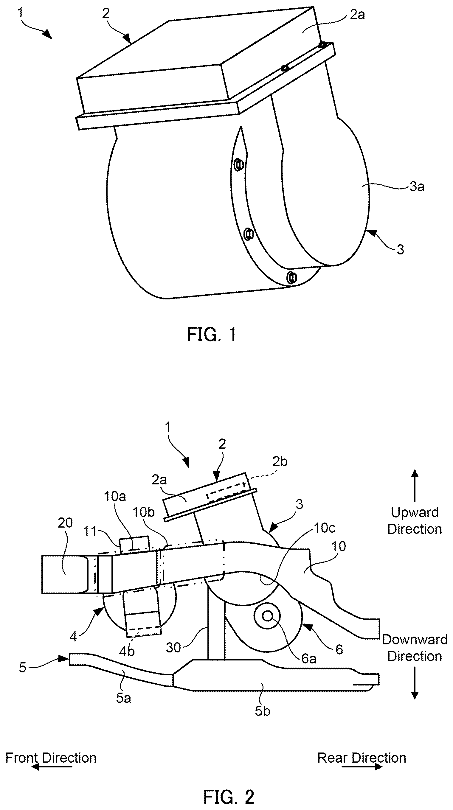
is an external view of an electric unit.
is a schematic configuration view of a vehicle mounting structure for the electric unit according to an embodiment.
is an external view of a generator.
is a view showing a state around a side member at the time of a vehicle collision.
DESCRIPTION OF EMBODIMENTS
Hereinafter, an embodiment of the present invention will be described with reference to the accompanying drawings.
is an external view of an electric unit 1 . is a schematic configuration view of a mounting structure for the electric unit 1 according to the present embodiment. is an external view of a generator 4 . As shown in , the electric unit 1 includes an inverter 2 and a motor 3 . The electric unit 1 is to be mounted on a vehicle. The vehicle is a series hybrid vehicle that travels by driving the motor 3 constituting a drive source of the vehicle using electric power generated by the generator 4 which is driven by power of an internal combustion engine. The inverter 2 is disposed above the motor 3 and has an integrated structure with the motor 3 . A case 2 a of the inverter 2 is fixed to a case 3 a of the motor 3 by bolt fastening. The motor 3 corresponds to a first motor.
As shown in , the electric unit 1 is fixed to a suspension member 5 via a support portion 30 . The support portion 30 supports the electric unit 1 from below. The electric unit 1 is disposed to be inclined forward with respect to the vehicle.
The suspension member 5 includes a high rigidity portion 5 a and a low rigidity portion 5 b in a vehicle front-rear direction. The high rigidity portion 5 a is a portion having rigidity higher than that of the low rigidity portion 5 b , and in the present embodiment, carbon steel is used for the high rigidity portion 5 a and aluminum alloy is used for the low rigidity portion 5 b . The high rigidity portion 5 a may be set, for example, by using a cross-sectional structure thicker than that of the low rigidity portion 5 b , or by providing a beam on an inner side of the vehicle in a vehicle lateral direction, that is, on an inner side portion of the suspension member 5 .
The high rigidity portion 5 a has a shape extending obliquely downward toward a rear of the vehicle. The low rigidity portion 5 b is disposed behind the high rigidity portion 5 a . The high rigidity portion 5 a is disposed at a front portion including a front end portion of the suspension member 5 . The low rigidity portion 5 b is disposed to be continuous with the high rigidity portion 5 a . The electric unit 1 is fixed to the low rigidity portion 5 b via the support portion 30 .
The inverter 2 is disposed above a side member 10 . The inverter 2 includes a high-voltage bus bar 2 b in the case 2 a . The high-voltage bus bar 2 b is a high-voltage terminal connection portion and is connected to the motor 3 . In the high-voltage bus bar 2 b , a high-voltage terminal has a bus bar structure, and is only partially insulated. Therefore, the high-voltage bus bar 2 b is considered to be a portion which is most desired to avoid interference with the side member 10 from the viewpoint of ensuring insulation at the time of a vehicle collision.
The side member 10 is connected to a bumper reinforcement 20 at a front of the vehicle, and extends from the bumper reinforcement 20 toward the rear of the vehicle. The side member 10 is disposed above the suspension member 5 .
The side member 10 includes a high rigidity portion 10 a and a low rigidity portion 10 b in the vehicle front-rear direction. The high rigidity portion 10 a is a portion having rigidity higher than that of the low rigidity portion 10 b . The high rigidity portion 10 a is set, for example, by using a material having a cross-sectional structure thicker than that of the low rigidity portion 10 b , by using a material having a higher strength than that of the low rigidity portion 10 b , or by providing a beam on the inner side of the vehicle in the vehicle lateral direction, that is, on an inner side portion of the side member 10 .
The low rigidity portion 10 b is disposed behind the high rigidity portion 10 a . The low rigidity portion 10 b is disposed to be continuous with the high rigidity portion 10 a . The low rigidity portion 10 b has a longitudinal cross-sectional shape when viewed from the front of the vehicle. Therefore, the low rigidity portion 10 b is relatively easily bent in the vehicle lateral direction at the time of the vehicle collision. The longitudinal cross-sectional shape contributes to securing a wide space in a motor room of the vehicle.
The high rigidity portion 10 a is disposed at a position overlapping with the high rigidity portion 5 a of the suspension member 5 in the vehicle front-rear direction. The high rigidity portion 10 a is disposed within a range in which the high rigidity portion 5 a is provided in the vehicle front-rear direction. The high rigidity portion 5 a corresponds to a first high rigidity portion, and the high rigidity portion 10 a corresponds to a second high rigidity portion. The high rigidity portion 10 a is disposed at a front end portion of the side member 10 .
As shown in , the generator 4 has a separate structure from the electric unit 1 . The generator 4 is fixed to the side member 10 via a bracket 11 . The generator 4 is fixed in a state of being suspended from the side member 10 by the bracket 11 . The motor 3 is provided with a speed reducer 6 . The motor 3 transfers power to an output shaft 6 a via the speed reducer 6 , and the power is transferred to drive wheels of the vehicle via the output shaft 6 a and further, a drive shaft of the vehicle connected to the output shaft 6 a . The output shaft 6 a is located below the motor 3 . The output shaft 6 a and the drive shaft are located below the side member 10 and above the suspension member 5 . The drive shaft can be disposed coaxially with the output shaft 6 a.
The bracket 11 is fixed, by bolt fastening, to a fixing portion 4 aa provided on the case 4 a of the generator 4 , and is fixed to the high rigidity portion 10 a of the side member 10 by bolt fastening. The bracket 11 is fixed to an upper surface of the side member 10 . The generator 4 is fixed to the high rigidity portion 10 a of the side member 10 via the bracket 11 .
The generator 4 is connected with a high-voltage connector 4 b . The high-voltage connector 4 b is a connector for connecting the inverter 2 and the generator 4 , and is disposed below the side member 10 . The high-voltage connector 4 b is connected, from the inner side of the vehicle, to a lower portion of the generator 4 in a state of being mounted on the vehicle. The high-voltage connector 4 b is disposed above the suspension member 5 . The generator 4 corresponds to a second motor.
The side member 10 includes a curved portion 10 c . The curved portion 10 c has an upwardly convex curved shape, and is disposed at a position overlapping with the inverter 2 in the vehicle front-rear direction. The side member 10 extends obliquely downward from the curved portion 10 c in the vehicle front-rear direction, and has a curved structure curved in a substantially arch shape as a whole. The curved portion 10 c is provided at a position overlapping the drive shaft of the vehicle connected to the output shaft 6 a in the vehicle front-rear direction. The curved portion 10 c is provided to avoid interference with the drive shaft of the vehicle, thereby securing a space for disposing the drive shaft.
Next, the main functions and effects of the present embodiment will be described.
is a view showing a state around the side member 10 at the time of the vehicle collision. Broken lines indicate a state before the vehicle collision. When the vehicle collides, the low rigidity portion 10 b of the side member 10 bends in the vehicle lateral direction, and absorbs energy. At this time, a portion of the low rigidity portion 10 b on the front of the vehicle is bent toward the inner side of the vehicle. The suspension member 5 moves toward the rear of the vehicle.
At this time, if the suspension member 5 is not broken, the electric unit 1 remains fixed to the suspension member 5 , and the inverter 2 cannot move upward in a direction away from the side member 10 . Therefore, there is a concern that the side member 10 bent inward may interfere with the inverter 2 . If the insulation of the inverter 2 is broken at this time, there is a concern that a short circuit may occur at a high voltage, and the safety against electric shock prevention may be impaired.
In particular, in the present embodiment, the side member 10 includes the curved portion 10 c , and the curved portion 10 c is disposed at the position overlapping with the inverter 2 in the vehicle front-rear direction. In this case, as a result of the side member 10 being easily bent upward in a convex manner at the time of the vehicle collision, a probability that the low rigidity portion 10 b is bent toward the inner side of the vehicle and interferes with the inverter 2 increases.
The vehicle mounting structure for the electric unit 1 according to the present embodiment includes the side member 10 , the suspension member 5 including the high rigidity portion 5 a and the low rigidity portion 5 b in the vehicle front-rear direction, and the electric unit 1 in which the inverter 2 and the motor 3 are integrated. The side member 10 includes the curved portion 10 c , and the curved portion 10 c is disposed at the position overlapping with the inverter 2 in the vehicle front-rear direction. The electric unit 1 is fixed to the low rigidity portion 5 b.
According to such a configuration, at the time of the vehicle collision, the high rigidity portion 5 a moves rearward without being broken. When the high rigidity portion 5 a pushes the low rigidity portion 5 b , a base portion of the high rigidity portion 5 a continuing to the low rigidity portion 5 b is pulled, and the low rigidity portion 5 b is broken. As a result, the electric unit 1 is brought into a free state due to the breakage of the low rigidity portion 5 b , and is moved upward to be pushed up. Accordingly, the inverter 2 moves in the direction away from the side member 10 , and thus interference between the inverter 2 and the side member 10 that is bent toward the inner side of the vehicle at the time of the vehicle collision is avoided. Further, when the electric unit 1 remains fixed to the suspension member 5 , the electric unit 1 may move toward the rear of the vehicle and interfere with a dash cross that separates a vehicle compartment and the motor room, but such a situation is also avoided. The fact that the generator 4 is disposed below the motor 3 also contributes to the pushing up of the electric unit 1 in the free state.
Further, according to such a configuration, the electric unit 1 in the free state due to the breakage of the low rigidity portion 5 b at the time of the vehicle collision moves upward, and thus the side member 10 that bends upward in a convex manner at the time of the vehicle collision can be avoided from interfering with the inverter 2 .
In the present embodiment, the high rigidity portion 5 a has the shape extending obliquely downward toward the rear of the vehicle.
According to such a configuration, the high rigidity portion 5 a moves rearward and downward with a space at the time of the vehicle collision, and a shearing force acts on the low rigidity portion 5 b , and as a result, the low rigidity portion 5 b can be easily broken. Accordingly, this configuration can also contribute to the pushing up of the electric unit 1 in the free state.
The vehicle mounting structure for the electric unit 1 according to the present embodiment further includes the side member 10 , and the inverter 2 is disposed above the side member 10 .
According to such a configuration, the interference between the side member 10 and the inverter 2 that is constituted by a high-voltage component at the time of the vehicle collision can be avoided more reliably.
In the present embodiment, the side member 10 includes the high rigidity portion 10 a whose position overlaps with the high rigidity portion 5 a of the suspension member 5 in the vehicle front-rear direction. The vehicle mounting structure for the electric unit 1 according to the present embodiment further includes the generator 4 which is fixed to the high rigidity portion 10 a of the side member 10 and has a separate structure from the electric unit 1 .
According to such a configuration, the generator 4 is fixed to the high rigidity portion 10 a outside a region of the low rigidity portion 10 b which is bent to the inner side of the vehicle at the time of the vehicle collision, and thus interference between the generator 4 and the side member 10 which is bent to the inner side of the vehicle can be avoided. In addition, the generator 4 is disposed at a position overlapping with the high rigidity portion 5 a where breakage does not occur in the vehicle front-rear direction, and thus interference between the suspension member 5 and the generator 4 can also be avoided due to the breakage at the time of the vehicle collision. Further, the electric unit 1 is formed separately from not only the generator 4 but also the internal combustion engine that drives the generator 4 , and thus the electric unit 1 is accordingly reduced in weight, and is easily moved upward at the time of the vehicle collision. As a result, it is easy to avoid the interference between the inverter 2 and the side member 10 .
The vehicle mounting structure for the electric unit 1 according to the present embodiment further includes the high-voltage connector 4 b connected to the generator 4 , and the high-voltage connector 4 b is disposed below the side member 10 .
According to such a configuration, interference between the high-voltage connector 4 b and the side member 10 can also be avoided.
Although the embodiment of the present invention has been described above, the above-mentioned embodiment is merely a part of application examples of the present invention, and does not mean that the technical scope of the present invention is limited to the specific configurations of the above-mentioned embodiment.
For example, in the above-described embodiment, a case where the inverter 2 is disposed above the side member 10 has been described. However, the inverter 2 may be partially disposed above the side member 10 , and in this case, a portion of the inverter 2 above the side member 10 may include the high-voltage bus bar 2 b . The high-voltage bus bar 2 b may be a high-voltage bus bar connected to the generator 4 or a high-voltage bus bar connected to a battery.
According to such a configuration, the side member 10 can also be avoided from interfering with the high-voltage bus bar 2 b which is most desired to avoid the interference with the side member 10 from the viewpoint of ensuring insulation.
Figures (2)
Citations
This patent cites (14)
- US7669688
- US9205749
- US2003/0011184
- US2011/0132676
- US2015/0107920
- US102019002655
- US2002362167
- US2006088871
- US2011-152841
- US2012-096746
- US2013095152
- US2017065439
- US2019018685
- US2019188884