Shear and Grip Device, System and Method
Abstract
Combination gripping and shearing effector device, systems and methods for both shearing and gripping in tandem with a remotely actuated effector tool used in robotic and remote processing of materials, where the gripping and shearing operate in tandem with one another. In a preferred embodiment, the device can include a pair of gripping jaws, with a pair of separately movable, and integrated shearing jaws within the gripping jaws. Hydraulic actuators can control the gripping jaws to grip material, followed by the shearing jaws shearing the material. The effector devices can be remotely controlled, hydraulically opening and closing the gripper and shear jaws with a single hydraulic control circuit.
Claims (9)
1. A shear and grip device, comprising: a pair of gripping jaws attached to a grip actuator; and a pair of shearing jaws within the pair of gripping jaws attached to a shearing actuator, wherein the grip actuator operates the gripper jaws and the shear actuator operates the shearing jaws in tandem, wherein the grip actuator includes a hydraulic operated pre-load piston that moves both the gripping jaws and the pair of shearing jaws to work together in a grip phase, and wherein the shearing actuator includes a shear hydraulic actuator piston to move the pair of shearing jaws further together in a shear phase, where the hydraulic operated pre-load piston is concentric to the shear hydraulic actuator piston.
4. A shear and grip device, comprising: a pair of pivoting gripping jaws attached to a grip actuator; and a pair of pivoting shearing jaws adjacent to the pair of pivoting gripping jaws attached to a shear actuator, wherein the grip actuator and the shear actuator causes the gripping jaws and shearing jaws to move together during a gripping phase, and the shear actuator causes the shearing jaws to continue to move together during a shear phase, wherein the grip actuator includes a preload piston for operating the pair of gripping jaws; and the shear actuator includes a shear piston for operator the pair of shear jaws, and wherein the preload piston is oriented concentric to the shear piston.
6. A method for gripping and shearing an object, comprising the steps of: providing a pair of pivoting gripping jaws attached to a grip actuator; providing a pair of pivoting shearing jaws adjacent to the pair of pivoting gripping jaws attached to a shear actuator; mounting the grip actuator and the shearing actuator to an arm assembly; providing the grip actuator with a preload piston for operating the pair of gripping jaws; and providing the shear actuator with a shear piston for operator the pair of shear jaws, wherein the preload piston is oriented concentric to the shear piston; actuating the gripping jaws and the shearing jaws to move together during a gripping phase; and actuating the shearing jaws to continue to move together during a shear phase.
Show 6 dependent claims
2. The shear and grip device of claim 1 , further comprising: a remote controller for operating the shear and grip device.
3. The shear and grip device of claim 1 , further comprising: a mount for mounting the shear and grip device to a remotely controlled robot.
5. The shear and grip device of claim 4 , wherein the preload piston includes a hydraulic preload piston, and the shear piston includes a hydraulic piston.
7. The method of claim 6 , wherein the preload piston includes a hydraulic preload piston, and the shear piston includes a hydraulic piston.
8. The method of claim 6 , further comprising the steps of: mounting the arm to a support; and remotely controlling the grip actuator and the shear actuator.
9. The method of claim 6 , further comprising the step of: gripping and shearing through pipes and conduits.
Full Description
Show full text →
CROSS REFERENCE TO RELATED APPLICATIONS
This application claims the benefit of priority to U.S. Provisional Application Ser. No. 63/254,571 filed Oct. 12, 2021, the entire disclosure which is incorporated herein by specific reference thereto.
FIELD OF INVENTION
This invention relates to remotely actuated effectors, and in particular to shear and grip devices, systems and methods for both shearing and gripping in tandem with a remotely actuated effector tool used in robotic and remote processing or manipulating of materials, debris or components.
BACKGROUND AND PRIOR ART
In robotic or remote processing of materials in an unknown or challenging environment, such as cleanup of debris or materials in radioactive, toxic or hazardous situations, it is often desirable to be able to pick up said debris, as well as to cut or resize that debris into smaller pieces. Picking up debris or pieces of debris is often done with a gripping device consisting of two jaws that can open and close on the debris, trapping it between the jaws. Cutting or resizing debris is also often done with a shearing device with two similar jaws, except with sharpened edges, to shear material as the two jaws pass each other.
Tool changers that allow one robotic arm to implement more than one end effector and switch between them are available, allowing for gripping and shearing ability on the same robot. Often, however, it would be beneficial to hold the material with a pair of gripper jaws, while shearing with a pair of shear jaws, requiring mounting and controlling two implements. Existing implements that can operate shearing and gripping functions in tandem are not available.
Thus, the need exists for solutions to the above problems with the prior art.
SUMMARY OF THE INVENTION
A primary objective of the present invention is to provide shear and grip devices, systems and methods for both shearing and gripping in tandem with a remotely actuated effector tool used in robotic and remote processing or manipulating of materials, debris or components
A secondary objective of the present invention is to provide shear and grip devices, systems and methods for both shearing and gripping in tandem with a remotely actuated effector tool that shares mechanical operating components for both using the tool for shearing and gripping actions
A further objective of the present invention is to provide shear and grip devices, systems and methods for both shearing and gripping in tandem with a remotely actuated effector tool that operates together via a single control mechanism, source or signal.
This device places a pair of gripper jaws around a pair of shear jaws so that material can be held by the gripper function, while actuating the shearing function to cut the material. The shear and gripper jaws work together with a single control mechanism to open and close in tandem.
A piece of material can be gripped and manipulated using the combination of the two pairs of jaws. When material needs to be cut the gripper function can be used to hold the material in position and the shear jaws can be actuated fully through their range of motion to effect shearing of the material.
The shear jaws are directly controlled via hydraulic, pneumatic, electric, or other means of opening and closing. The gripper jaws are positioned in such a way that they can open independently of the shear jaws and close to a position even with the primary (shearing) faces of the shear jaws. A preload mechanism is used to push the gripper jaws against the shear jaws. This preload can be created with air or mechanical springs, hydraulic or pneumatic pressure, or other methods.
This jaw and preload arrangement allows the gripper jaws to open as the shear jaws open and close when the shear jaws close, requiring only a single point of control (be it electric, hydraulic, pneumatic, etc.). When the gripper jaws contact a piece of material they stop closing and the preload is used to hold the grippers closed on the subject material, independent of whether the shear jaws continue to close. If the shear jaws continue through the closing and shearing motion the preload on the gripper jaws holds position based on the preload and move out of the way as required by the shear jaw loading. Opening the shear jaws pushes the gripper jaws open, releasing the hold on the material.
An embodiment of a shear and grip device, can include a pair of gripping jaws attached to an actuator, and a pair of shearing jaws within the pair of gripping jaws attached to the actuator, wherein the actuator operates the gripper jaws and shearing jaws in tandem.
The actuator can be selected from at least one of: hydraulic, pneumatic, electric, magnetic, mechanical screw, spring, and any combination thereof, for opening and closing the pair of gripping jaws and the pair of shearing jaws.
The actuator can include a preload piston for operating the pair of gripping jaws; and a shear piston for operator the pair of shear jaws.
The preload piston can be oriented concentric to the shear piston.
The preload piston can include a hydraulic preload piston, and the shear piston can include a hydraulic piston.
The preload piston and the shear piston can be selected from at least one of: hydraulic, pneumatic, electric, magnetic, mechanical screw, spring, and any combination thereof, for opening and closing the pair of gripping jaws and the pair of shearing jaws.
The shear and grip device can include a remote controller for operating the shear and grip device.
The shear and grip device can include a mount for mounting the shear and grip device to a remotely controlled robot.
The shear and grip device can include a mount for mounting the shear and grip device to anyone of a backhoe, a skid-steer, and demolition equipment.
A shear and grip device, and include a pair of pivoting gripping jaws attached to a grip actuator, and a pair of pivoting shearing jaws adjacent to the pair of pivoting gripping jaws attached to a shear actuator, wherein the grip actuator and the shear actuator causes the gripping jaws and shearing jaws to move together during a gripping phase, and the shear actuator causes the shearing jaws to continue to move together during a shear phase.
A method for gripping and shearing an object, can include the steps of providing a pair of pivoting gripping jaws attached to a grip actuator; providing a pair of pivoting shearing jaws adjacent to the pair of pivoting gripping jaws attached to a shear actuator; mounting the grip actuator and the shearing actuator to an arm assembly; actuating the gripping jaws and the shearing jaws to move together during a gripping phase; and actuating the shearing jaws to continue to move together during a shear phase.
The method can further comprise the step of: providing the grip actuator with a preload piston for operating the pair of gripping jaws; and providing the shear actuator with a shear piston for operator the pair of shear jaws.
The preload piston can be oriented concentric to the shear piston.
The preload piston can include a hydraulic preload piston, and the shear piston can include a hydraulic piston.
The method can further comprise the steps of: mounting the arm to a support; and remotely controlling the grip actuator and the shear actuator.
The method can further comprise the step of gripping and shearing through pipes and conduits.
Further objects and advantages of this invention will be apparent from the following detailed description of the presently preferred embodiments which are illustrated schematically in the accompanying drawings.
BRIEF DESCRIPTION OF THE FIGURES
The drawing figures depict one or more implementations in accord with the present concepts, by way of example only, not by way of limitations. In the figures, like reference numerals refer to the same or similar elements.
A is a front view of a preferred embodiment of a shear and grip device shown with shear and gripper jaws open.
B is a side View of the preferred embodiment of the shear and grip device of A shown with shear and gripper jaws open
A is a front view of the preferred embodiment of the shear and grip device of A shown with shear and gripper jaws open
B is a cross-sectional view of the preferred embodiment of the shear and grip device of A along arrows A-A shown with shear and gripper jaws open
A is a front view of the preferred embodiment of the shear and grip device of A shown with shear and gripper jaws partially closed to a gripping Position.
B is a side view of the preferred embodiment of the shear and grip device shown in A with shear and gripper jaws partially closed to a gripping position.
A is a front view of the referred embodiment of A with shear and grip device with shear and gripper jaws Partially Closed to a Gripping Position.
B is a cross-sectional view of A along arrows B-B of the preferred embodiment of the shear and grip device shown with shear and gripper jaws partially closed to a gripping position.
A is a front view of the preferred embodiment of the shear and grip Device of A shown with shear and gripper jaws fully closed to the fully sheared position.
B is a side view of the preferred embodiment of the shear and grip device of A shown with shear and gripper jaws fully closed to the fully sheared position.
A is a front view of the preferred embodiment of shear and grip device of A shown with shear and gripper jaws fully closed to the fully sheared position.
B is a cross-sectional view along arrows C-C of A with shear and gripper jaws fully closed to the fully sheared position.
is an exploded view of the preferred embodiment of the shear and grip device shown in A- 6 B .
A is a perspective partial view of the arm assembly with shear and gripper jaws fully open.
B is a perspective of the arm assembly with shear and gripper jaws of A slightly closed.
C is a perspective of the arm assembly with shear and gripper jaws of B closed into a full grip position.
A- 9 B is a perspective view of the arm assembly with shear and gripper jaws of C during the shearing phase.
A is a perspective view of the arm assembly with shear and gripper jaws of C with shear jaws in a partial shearing position.
B is a perspective view of the arm assembly with shear and gripper jaws of A with shear jaws in a fully shearing position.
A is another perspective view of A with shear and gripper jaws fully open about a pipe/conduit.
B is another perspective view of B with shear and gripper jaws slightly closed about a pipe/conduit.
C is another perspective view of C with shear and gripper jaws closed into a full grip about a pipe/conduit.
D is another perspective view of A with shear and gripper jaws, and shear jaws in a partial shearing position into the pipe/conduit.
E is another perspective view of B with shear and gripper jaws, and shear jaws in fully shearing position through a pipe/conduit.
is a perspective view of the shear and grip device of A- 7 mounted to a remotely operated robot within a hazardous materials tank.
DESCRIPTION OF THE PREFERRED EMBODIMENTS
Before explaining the disclosed embodiments of the present invention in detail it is to be understood that the invention is not limited in its applications to the details of the particular arrangements shown since the invention is capable of other embodiments. Also, the terminology used herein is for the purpose of description and not of limitation.
In the Summary above and in the Detailed Description of Preferred Embodiments and in the accompanying drawings, reference is made to particular features (including method steps) of the invention. It is to be understood that the disclosure of the invention in this specification does not include all possible combinations of such particular features. For example, where a particular feature is disclosed in the context of a particular aspect or embodiment of the invention, that feature can also be used, to the extent possible, in combination with and/or in the context of other particular aspects and embodiments of the invention, and in the invention generally.
In this section, some embodiments of the invention will be described more fully with reference to the accompanying drawings, in which preferred embodiments of the invention are shown. This invention may, however, be embodied in many different forms and should not be construed as limited to the embodiments set forth herein. Rather, these embodiments are provided so that this disclosure will be thorough and complete, and will convey the scope of the invention to those skilled in the art. Like numbers refer to like elements throughout, and prime notation is used to indicate similar elements in alternative embodiments.
Other technical advantages may become readily apparent to one of ordinary skill in the art after review of the following figures and description.
It should be understood at the outset that, although exemplary embodiments are illustrated in the figures and described below, the principles of the present disclosure may be implemented using any number of techniques, whether currently known or not. The present disclosure should in no way be limited to the exemplary implementations and techniques illustrated in the drawings and described below.
Unless otherwise specifically noted, articles depicted in the drawings are not necessarily drawn to scale.
A list of components will now be described:
•
• 1 shear and grip device • 10 A gripper jaw • 10 B gripper jaw • 20 A shear jaw • 20 B shear jaw • 30 preload mechanism • 40 A preload cam follower • 40 B preload cam follower • 50 preload piston • 60 shear hydraulic actuator piston • 70 A shear linkage • 70 B shear linkage • 80 A gripper pivot • 80 B gripper pivot • 90 shear pivot • 100 A shear jaw/gripper jaw interface • 100 B shear jaw/gripper jaw interface • 110 shear hydraulic actuator body • 150 arm assembly
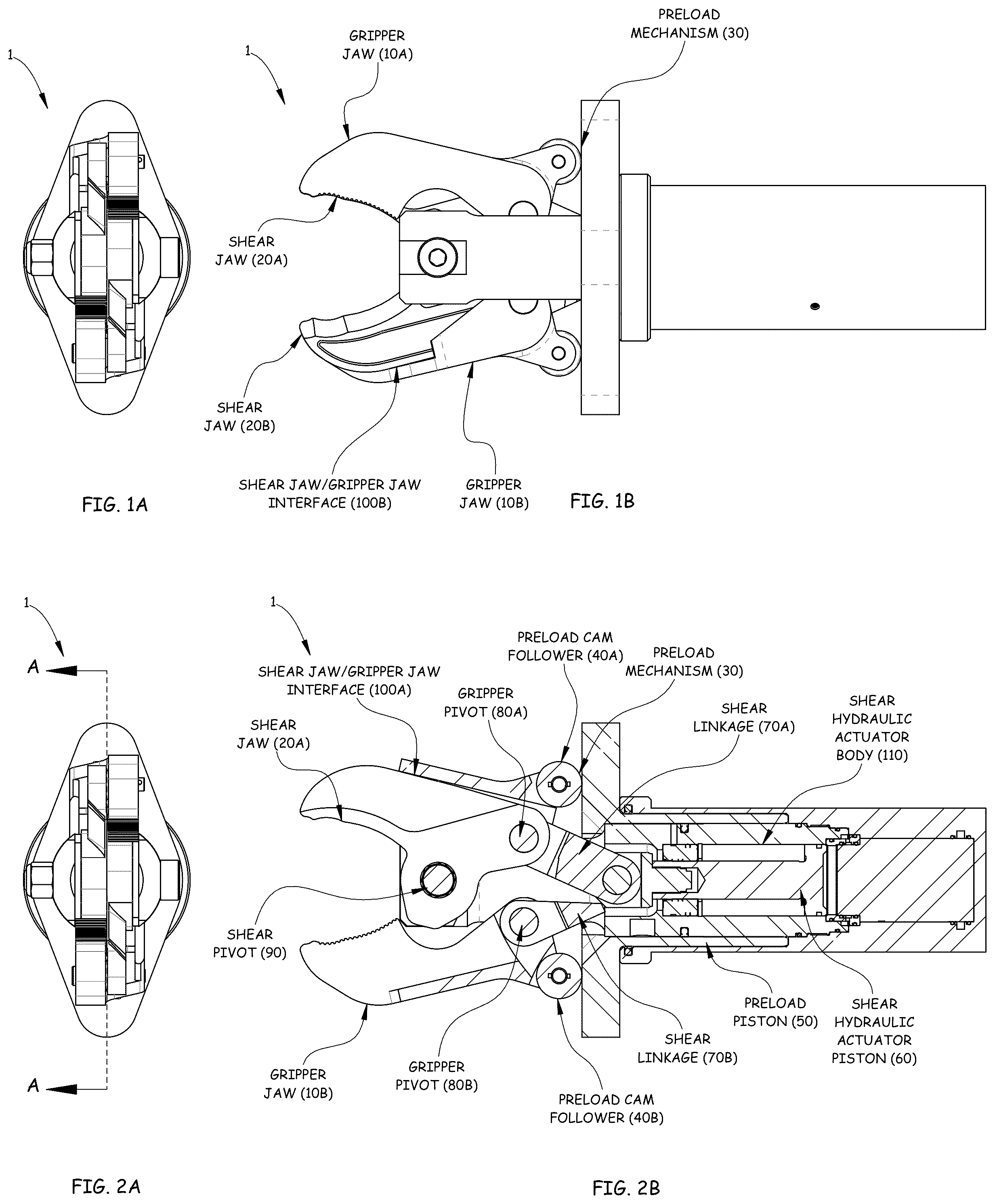
A is a front view of a preferred embodiment of a shear and grip device 1 shown with gripper jaws 10 A, 10 B and shear jaws 20 A, 20 B open. B is a side View of the preferred embodiment of the shear and grip device 1 of A shown with gripper jaws 10 A, 10 B and shear jaws 20 A, 20 B open.
A is a front view of the preferred embodiment of the shear and grip device 1 of A shown with gripper jaws 10 A, 10 B and shear jaws 20 A, 20 B open. B is a cross-sectional view of the preferred embodiment of the shear and grip device 1 of A along arrows A-A shown with gripper jaws 10 A, 10 B and shear jaws 20 A, 20 B open
A is a front view of the preferred embodiment of the shear and grip device 1 of A shown with shear and gripper jaws partially closed to a gripping Position. B is a side view of the preferred embodiment of the shear and grip device shown 1 in A with shear and gripper jaws partially closed to a gripping position.
A is a front view of the referred embodiment of A with shear and grip device 1 with shear and gripper jaws partially Closed to a gripping Position. B is a cross-sectional view of the preferred embodiment of the shear and grip device 1 of A along arrows B-B of the preferred embodiment of the shear and grip device 1 shown with shear and gripper jaws partially closed to a gripping position.
A is a front view of the preferred embodiment of the shear and grip device 1 of A shown with shear and gripper jaws fully closed to the fully sheared position. B is a side view of the preferred embodiment of the shear and grip device 1 of A shown with shear and gripper jaws fully closed to the fully sheared position.
A is a front view of the preferred embodiment of shear and grip device 1 of A shown with shear and gripper jaws fully closed to the fully sheared position. B is a cross-sectional view of the preferred embodiment of the shear and grip device 1 of A along arrows C-C of with shear and gripper jaws fully closed to the fully sheared position.
is an exploded view of the preferred embodiment of the shear and grip device shown in A- 6 B .
Referring to , the preferred embodiment can use a hydraulic operated Shear Piston 60 to operate the shear jaws 20 A, 20 B via two shear linkages 70 A, 70 B. The shear jaws 20 A, 20 B rotate around the shear pivot 90 to open and close via movement from the shear linkages 70 A, 70 B as the shear piston 60 actuates.
The gripper jaws 10 A & 10 B pivot around the gripper pivots 80 A, 80 B on the shear jaws so that the position of the two is related based on the preload mechanism 30 , the shear jaw position and the size of anything held within the jaws 10 A, 10 B. The preload mechanism 30 pushes the gripper jaws 10 A, 10 B closed and maintains them pressed up against anything impeding that motion. If a piece of material or debris is held in the gripper jaws they will be maintained with pressure against the material or debris. If nothing is held within the gripper jaws, they will close against the shear jaws 20 A, 20 B at the shear jaw/gripper jaw interfaces 100 A, 100 B.
When the shear jaws 20 A, 20 B open, they can push the gripper jaws 10 A, 10 B open. When the shear jaws 20 A, 20 B close the gripper jaws 10 A, 10 B are close around them by the preload mechanism 30 .
Shear jaws 20 A, 20 B can be directly controlled via hydraulic, pneumatic, electric, or other means of opening and closing.
In this Embodiment the preload mechanism 30 consists of a preload piston 50 that is pressurized with constant or nearly constant pressure.
A flat face on the preload piston 50 applies a continuous load against the preload cam followers 40 A, 40 B, forcing the gripper jaws 10 A, 10 B closed.
In this Embodiment the preload piston 50 can be a hydraulic piston oriented concentric to the shear piston 60 .
Alternatively, the preload piston 50 can be one or more independent pistons, a mechanical spring, air spring, pneumatic piston, or other preload device.
As the shear jaws 20 A, 20 B open and close the gripper jaws 10 A, 10 B follow until the point something is gripped between the jaws. At that point, if the shear jaws 20 A, 20 B continue to close the gripper jaws 10 A, 10 B will lose contact at the shear jaw/gripper jaw Interface 100 A and the shear jaws 20 A, 20 B will shear the material independently of the gripping action of the gripper jaws 10 A, 10 B.
A- 8 C show perspective views of the arm assembly 150 with shear jaws 20 A, 20 B and gripper jaws 10 A, 10 B moving together during the gripping phase.
A is a perspective partial view of the arm assembly with shear jaws 20 A, 20 B and gripper jaws 10 A, 10 B fully open.
B is a perspective of the arm assembly 150 with shear jaws 20 A, 20 B and gripper jaws 10 A, 10 B of A slightly closed.
C is a perspective of the arm assembly 150 with shear jaws 20 A, 20 B and gripper jaws 10 A, 10 B of B closed into a full grip position.
A is a perspective view of the arm assembly 150 with shear jaws 20 A, 20 B and gripper jaws 10 A, 10 B of C with shear jaws 20 A, 20 B in a partial shearing position.
B is a perspective view of the arm assembly 150 with shear jaws 20 A, 20 B and gripper jaws 10 A, 10 B of A with shear jaws 20 A, 20 B in a fully shearing position.
A- 10 E are partial views of the arm assembly with shear jaws, 20 A, 20 B and gripper jaws 10 A, 10 B of A- 9 B , moving from the gripping phase about a pipe/conduit 200 through the shearing phase.
A is another perspective view of A with shear jaws 20 A, 20 B and gripper jaws 10 A, 10 B fully open about a pipe/conduit 200 .
B is another perspective view of B with shear jaws 20 A, 20 B and gripper jaws 10 A, 10 B slightly closed about a pipe/conduit 200 .
C is another perspective view of C with shear jaws 20 A, 20 B and gripper jaws 10 A, 10 B closed into a full grip about a pipe/conduit 200 .
D is another perspective view of A with shear jaws 20 A, 20 B and gripper jaws 10 A, 10 B, and shear jaws 20 A, 20 B in a partial shearing position into the pipe/conduit 200 .
E is another perspective view of B with shear jaws, 20 A, 20 B and gripper jaws 10 A, 10 B, and shear jaws 20 A, 20 B n fully shearing position through the pipe/conduit 200 .
A prototype of the device 1 was developed with hydraulic pressures up to approximately 15,000 psi (pounds per square inch). Testing showed the grip jaws 10 A, 10 B able to lift up to an approximately 70 pound object. The shear jaws 20 A, 20 B were manufactured to increase thicknesses to add more strength, with a stronger, more ductile material with a hardened shear edge to allow the shear jaws 20 A, 20 B to cut through an approximately 2 inch schedule 80 steel pipe. Further testing showed the shear jaws 20 A, 20 B cutting through an approximately ¾ inch diameter stainless steel wire rope.
is a perspective view of the shear and grip device 1 and arm assembly 150 of A- 10 E mounted to a remotely operated robot 300 within a hazardous materials tank 250 . A remote Operator 400 outside of the hazardous materials tank can operate Operator Controls 400 to control the shear and grip device 1 .
Applications for the device 1 can include systems and devices shown and described in U.S. Pat. Nos. 10,280,063; 10,406,571; 10,786, 905; 10,864,640; 11,031,149; 11, 267,024; 11, 311,920; and 11,413,666 assigned to the same applicant AGI Engineering Inc., as the subject patent application, which are all incorporated by reference in their entirety.
Either or both the shear jaws 20 A, 20 B and grip jaws 10 A, 10 B can be directly controlled via hydraulic, pneumatic, electric, spring or other means of opening and closing, or any combination thereof.
Actuator(s) for either or both the shear jaws 20 A, 20 B and grip jaws 10 A, 10 B can be selected from at least one of: hydraulic, pneumatic, electric, magnetic, mechanical screw, spring, and any combination thereof, for opening and closing the pair of gripping jaws and the pair of shearing jaws.
The novel shear and grip effector device 1 can be mounted on other devices, machines, and the like, such as but not limited to backhoes, skid-steers, other demolition equipment, and the like.
Although specific advantages have been enumerated above, various embodiments may include some, none, or all of the enumerated advantages.
Modifications, additions, or omissions may be made to the systems, apparatuses, and methods described herein without departing from the scope of the disclosure. For example, the components of the systems and apparatuses may be integrated or separated. Moreover, the operations of the systems and apparatuses disclosed herein may be performed by more, fewer, or other components and the methods described may include more, fewer, or other steps. Additionally, steps may be performed in any suitable order. As used in this document, “each” refers to each member of a set or each member of a subset of a set.
To aid the Patent Office and any readers of any patent issued on this application in interpreting the claims appended hereto, applicants wish to note that they do not intend any of the appended claims or claim elements to invoke 35 U.S.C. 112 (f) unless the words “means for” or “step for” are explicitly used in the particular claim.
While the invention has been described, disclosed, illustrated and shown in various terms of certain embodiments or modifications which it has presumed in practice, the scope of the invention is not intended to be, nor should it be deemed to be, limited thereby and such other modifications or embodiments as may be suggested by the teachings herein are particularly reserved especially as they fall within the breadth and scope of the claims here appended.
Figures (8)
Citations
This patent cites (13)
- US4771540
- US10280063
- US10406571
- US10786905
- US10864640
- US11031149
- US11267024
- US11311920
- US11413666
- US106677234
- US112059272
- US101893851
- USWO-2020137158