Surgical System Including Adapter Assembly with Worm Gear Assembly
Abstract
A surgical system includes an end effector, a handle assembly that operates the end effector, and an adapter assembly that connects the end effector to the handle assembly. The adapter assembly includes an adapter housing, an outer tube, at least one gear assembly, and a worm gear assembly. The adapter housing has a proximal end portion connected to a distal end portion of the handle assembly. The outer tube extends distally from the adapter housing and supports the end effector on a distal end portion of the outer tube. The worm gear assembly is engaged with the at least one gear assembly and rotatable with the at least one gear assembly in the adapter housing to operate the end effector.
Claims (20)
1. An adapter assembly for selectively interconnecting an end effector to a handle assembly supporting a motor, the motor configured to impart drive force from the handle assembly to the end effector to operate the end effector, the adapter assembly comprising: an adapter housing having a proximal end portion configured to couple to a distal end portion of the handle assembly; an outer tube extending distally from the adapter housing and configured to support the end effector on a distal end portion of the outer tube; and a drive assembly supported in the proximal end portion of the adapter housing and including: at least one gear assembly; a worm gear assembly engaged with the at least one gear assembly and configured to rotate the at least one gear assembly in the adapter housing as the worm gear assembly rotates in the adapter housing to operate the end effector; and a driven member operably coupled to the at least one gear assembly and configured to axially translate through the outer tube.
11. A surgical stapling apparatus, comprising: an end effector; a handle assembly configured to operate the end effector; and an adapter assembly for selectively interconnecting the end effector and the handle assembly, the adapter assembly including: an adapter housing having a proximal end portion coupled to a distal end portion of the handle assembly; an outer tube extending distally from the adapter housing and supporting the end effector on a distal end portion of the outer tube; and a drive assembly supported in the adapter housing and including: at least one gear assembly; and a worm gear assembly engaged with the at least one gear assembly to rotate the at least one gear assembly in the adapter housing as the worm gear assembly rotates in the adapter housing to articulate the end effector.
20. A surgical system, comprising: an end effector; a handle assembly configured to operate the end effector; and an adapter assembly that connects the end effector to the handle assembly, the adapter assembly including: an adapter housing having a proximal end portion connected to a distal end portion of the handle assembly; an outer tube extending distally from the adapter housing and supporting the end effector on a distal end portion of the outer tube; at least one gear assembly; and a worm gear assembly engaged with the at least one gear assembly and rotatable with the at least one gear assembly in the adapter housing to operate the end effector.
Show 17 dependent claims
2. The adapter assembly of claim 1 , further including a firing assembly that extends through the drive assembly and into the outer tube.
3. The adapter assembly of claim 2 , wherein the firing assembly includes a firing shaft that rotates independent of the drive assembly to actuate a firing function of the end effector.
4. The adapter assembly of claim 1 , wherein the driven member includes a cable.
5. The adapter assembly of claim 4 , wherein the at least one gear assembly includes a capstan, and wherein the cable is coupled to the capstan.
6. The adapter assembly of claim 5 , wherein the cable is axially translatable in response to rotation of the worm gear assembly.
7. The adapter assembly of claim 5 , wherein the adapter housing includes an outer housing and an inner housing, the inner and outer housings supporting the drive assembly therein.
8. The adapter assembly of claim 1 , wherein the drive assembly is a cable drive assembly and the driven member includes at least one cable.
9. The adapter assembly of claim 8 , wherein the cable drive assembly further includes at least one pulley supporting the at least one cable and configured to direct the at least one cable into the outer tube.
10. The adapter assembly of claim 1 , wherein the outer tube defines a longitudinal axis that extends between proximal and distal ends of the outer tube, the worm gear assembly including a worm gear supported on a rotatable shaft member that extends in parallel relationship to the longitudinal axis of the outer tube.
12. The surgical stapling apparatus of claim 11 , further including a firing assembly that extends through the drive assembly and into the outer tube.
13. The surgical stapling apparatus of claim 12 , wherein the firing assembly includes a firing shaft that rotates independent of the drive assembly to actuate a firing function of the end effector.
14. The surgical stapling apparatus of claim 11 , further comprising a driven member operably coupled to the at least one gear assembly and configured to axially translate through the outer tube.
15. The surgical stapling apparatus of claim 14 , wherein the at least one gear assembly includes a capstan that rotates in response to rotation of the at least one gear assembly, and wherein the driven member includes a cable, the cable coupled to the capstan.
16. The surgical stapling apparatus of claim 15 , wherein the cable is axially translatable in response to rotation of the worm gear assembly.
17. The surgical stapling apparatus of claim 15 , wherein the adapter housing includes an outer housing and an inner housing, the inner and outer housings supporting the drive assembly therein.
18. The surgical stapling apparatus of claim 11 , wherein the drive assembly includes at least one cable coupled to the at least one gear assembly.
19. The surgical stapling apparatus of claim 18 , wherein the drive assembly further includes at least one pulley supporting the at least one cable and configured to direct the at least one cable into the outer tube.
Full Description
Show full text →
CROSS-REFERENCE TO RELATED APPLICATIONS
This application is a continuation of U.S. patent application Ser. No. 17/987,990, filed Nov. 16, 2022, which continuation of U.S. patent application Ser. No. 17/034,490, filed Sep. 28, 2020, now U.S. Pat. No. 11,504,123, which is a continuation of U.S. patent application Ser. No. 15/491,268, filed Apr. 19, 2017, now U.S. Pat. No. 10,799,239, which claims the benefit of U.S. Provisional Patent Application Ser. No. 62/333,584, filed May 9, 2016, the entire contents of each of which are incorporated by reference herein.
TECHNICAL FIELD
The present disclosure relates to adapter assemblies for use in surgical systems. More specifically, the present disclosure relates to adapter assemblies for use with, and to electrically and mechanically interconnect, electromechanical surgical devices and surgical end effectors, and to surgical systems including handheld electromechanical surgical devices and adapter assemblies for connecting surgical end effectors to the handheld electromechanical surgical devices.
BACKGROUND
A number of surgical device manufacturers have developed product lines with proprietary powered drive systems for operating and/or manipulating a surgical device. In many instances the surgical devices include a powered handle assembly, which is reusable, and a disposable end effector or the like that is selectively connected to the powered handle assembly prior to use and then disconnected from the end effector following use in order to be disposed of or in some instances, sterilized for re-use.
Many of the existing end effectors for use with many of the existing powered surgical devices and/or handle assemblies are driven by a linear force. For example, end effectors for performing endo-gastrointestinal anastomosis procedures, end-to-end anastomosis procedures and transverse anastomosis procedures, each typically require a linear driving force in order to be operated. These end effectors are not compatible with surgical devices and/or handle assemblies that use a rotary motion to deliver power or the like.
In order to make the linear driven end effectors compatible with powered surgical devices and/or handle assemblies that use a rotary motion to deliver power, adapters and/or adapter assemblies are used to interface between and interconnect the linear driven end effectors with the powered rotary driven surgical devices and/or handle assemblies. Many of these adapter and/or adapter assemblies are complex devices including many parts and requiring extensive labor to assemble.
Adapter concepts often include a cable system for distal rotation and/or articulation. Some designs of cable systems include pulleys or lead screws with counter-directional threads to generate linear motion. Consistent with stroke dynamics, lead screw designs can require additional length to accommodate coordinated cable take-up and release. By comparison, pulley designs can be more compact than lead screw designs, but typically require different considerations including those associated with assembly and tensioning.
Accordingly, a need exists to develop adapters and/or adapter assemblies that incorporate fewer parts, are less labor intensive to assemble, and are ultimately more economical to manufacture. Specifically, a need exits to develop such adapters and/or adapter assemblies with improved pulley designs that simplify manufacturing and assembly as well as improve cable tensioning.
SUMMARY
According to an aspect of the present disclosure, an adapter assembly is provided. The adapter assembly selectively interconnects an end effector that is configured to perform a function and a surgical device that is configured to operate the end effector. The adapter assembly includes an outer tube having a distal end and a proximal end, a housing secured to the proximal end of the outer tube, and a cable drive assembly supported by the housing.
The cable drive assembly includes a worm gear, a cable gear coupled to the worm gear and rotatable in response to rotation of the worm gear, a capstan coupled to the cable gear and rotatable in response to rotation of the cable gear, and a cable coupled to the capstan. The cable may be axially translatable in response rotation of the capstan to actuate a function of the end effector while connected to the distal end of the outer tube.
In certain embodiments of the adapter assembly, the cable drive assembly may include a second worm gear, a second cable gear coupled to the second worm gear, a second capstan coupled to the second cable gear, and a second cable coupled to the second capstan. The second cable may be axially translatable in response to rotation of one or more of the second worm gear, the second cable gear, and the second capstan.
In some embodiments of the adapter assembly, the cable drive assembly may further include one or more pulleys supporting the cable and configured to direct the cable into the outer tube.
In certain embodiments of the adapter assembly, the cable drive assembly may further include a body portion that supports the worm gear and the cable gear in contacting relation with one another.
The adapter assembly may further include a firing assembly that extends through the cable drive assembly and into the outer tube. In some embodiments, the firing assembly may include a firing shaft that rotates independent of the cable drive assembly to actuate a firing function of the end effector.
The housing of the adapter assembly may include an outer housing and an inner housing that support the cable drive assembly therein.
In some embodiments of the adapter assembly, the outer tube defines a longitudinal axis that extends between the proximal and distal ends of the outer tube. The worm gear may be supported on a shaft member that extends in parallel relationship to the longitudinal axis of the outer tube. The shaft member may be rotatable to rotate the worm gear.
According to another aspect of the present disclosure, a surgical stapling apparatus is provided. The surgical stapling apparatus includes an end effector, a surgical device configured to operate the end effector, and an adapter assembly for selectively interconnecting the end effector and the surgical device.
The adapter assembly of the surgical stapling apparatus includes an outer tube having a distal end and a proximal end, a housing secured to the proximal end of the outer tube, and a cable drive assembly supported by the housing. The cable drive assembly includes a worm gear, a cable gear coupled to the worm gear, a capstan coupled to the cable gear, and a cable coupled to the capstan. The cable may be axially translatable in response rotation of one or more of the worm gear, the cable gear, and the capstan.
The adapter assembly of the surgical stapling apparatus may further include a firing assembly that extends through the cable drive assembly and into the outer tube. The firing assembly may include a firing shaft that rotates independent of the cable drive assembly to actuate a firing function of the end effector.
In some embodiments of the surgical stapling apparatus, the cable drive assembly may further include a second worm gear, a second cable gear coupled to the second worm gear, a second capstan coupled to the second cable gear, and a second cable coupled to the second capstan. The second cable may be axially translatable in response to rotation of one or more of the second worm gear, the second cable gear, and the second capstan.
In certain embodiments of the surgical stapling apparatus, the housing of the adapter assembly may include an outer housing and an inner housing. The inner and outer housings may support the cable drive assembly therein.
In some embodiments of the surgical stapling apparatus, the cable drive assembly may further include one or more pulleys supporting the cable and configured to direct the cable into the outer tube.
In certain embodiments of the surgical stapling apparatus, the cable drive assembly may further include a body portion that supports the worm gear and the cable gear in contacting relation with one another.
In some embodiments of the surgical stapling apparatus, the outer tube of the adapter assembly defines a longitudinal axis that extends between the proximal and distal ends of the outer tube. The worm gear may be supported on a shaft member that extends in parallel relationship to the longitudinal axis of the outer tube. The shaft member may be rotatable to rotate the worm gear.
According to yet another aspect of the present disclosure, an adapter assembly for selective connection to a surgical device is provided. The adapter assembly includes an outer tube having a distal end and a proximal end, a housing secured to the proximal end of the outer tube, and a cable drive assembly supported by the housing. The cable drive assembly includes a worm gear drive assembly, a cable gear assembly coupled to the worm gear drive assembly, and one or more cables coupled to the cable gear assembly and axially translatable within the outer tube.
In some embodiments, the cable drive assembly may further include a second worm gear, a second cable gear coupled to the second worm gear, a second capstan coupled to the second cable gear, and a second cable coupled to the second capstan.
Further details and aspects of exemplary embodiments of the present disclosure are described in more detail below with reference to the appended figures.
BRIEF DESCRIPTION OF THE DRAWINGS
The accompanying drawings, which are incorporated in and constitute a part of this specification, illustrate embodiments of the disclosure and, together with a general description of the disclosure given above, and the detailed description of the embodiment(s) given below, serve to explain the principles of the disclosure, wherein:
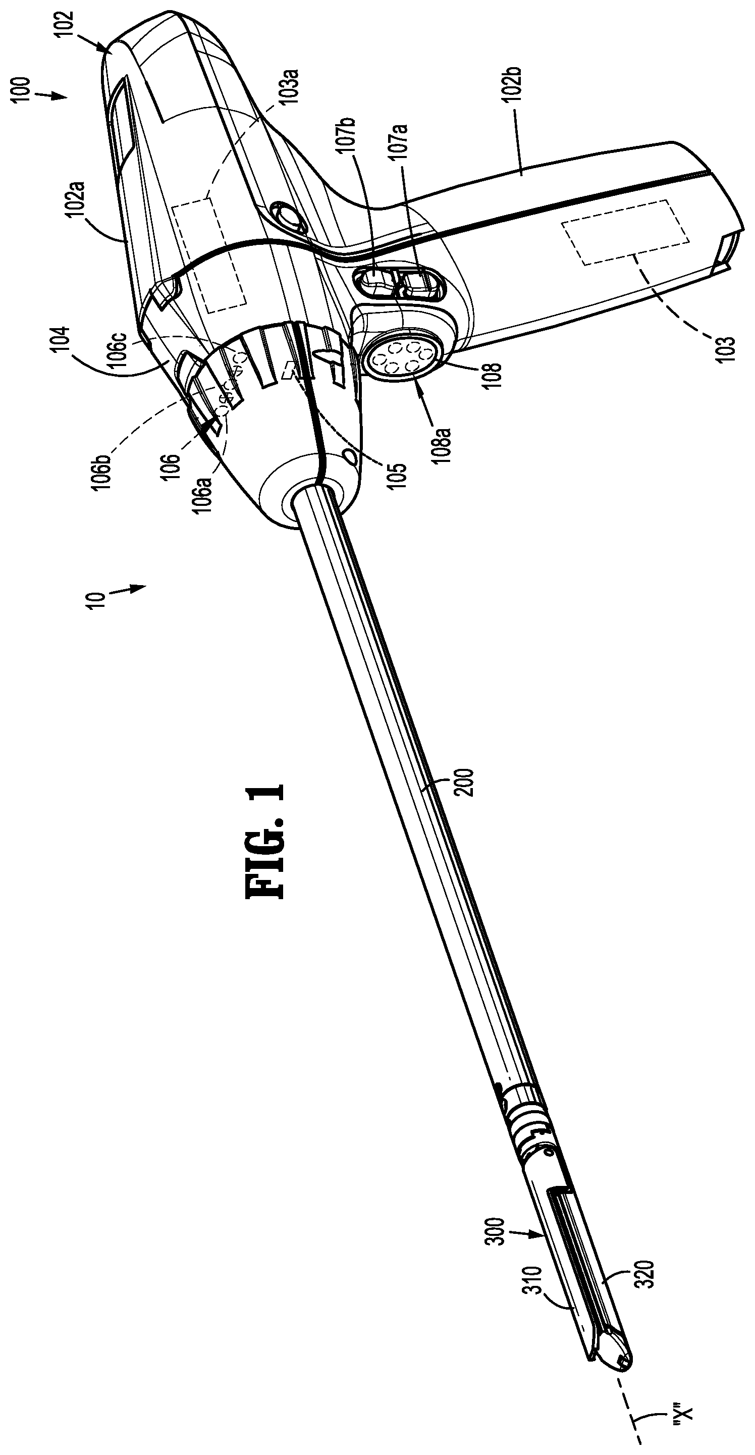
is a perspective view of an electromechanical surgical system in accordance with the principles of the present disclosure;
A is a perspective view of an adapter assembly of the electromechanical surgical system of ;
B is a perspective view of the indicated area of detail shown in A ;
is an enlarged, top, perspective view of a proximal portion of the adapter assembly of , the proximal portion of the adapter assembly shown with a portion of an outer housing thereof removed for clarity;
is a perspective view, with parts separated, of the proximal portion of the adapter assembly of ;
is an enlarged, perspective view, of the indicated area of detail shown in ;
is an enlarged, perspective view of a distal housing of the adapter assembly of ;
is a perspective view, with parts separated, of a drive system of the adapter assembly of ;
is a cross-sectional view of the adapter assembly of as taken along section line 8 - 8 shown in ;
is a cross-sectional view of a portion of the adapter assembly of as taken along section line 9 - 9 shown in ;
is a cross-sectional view of a portion of the adapter assembly of as taken along section line 10 - 10 shown in ;
is a perspective view, with parts separated, of an end effector of the electromechanical surgical system of ;
is a perspective view illustrating cables of the drive system of being tensioned with tensioning devices;
is a cross-sectional view of as taken along section line 13 - 13 shown in ; and
is a perspective view of the drive system of and of a tensioning device.
DETAILED DESCRIPTION
Electromechanical surgical systems of the present disclosure include surgical devices in the form of powered handheld electromechanical instruments configured for selective attachment to a plurality of different end effectors that are each configured for actuation and manipulation by the powered handheld electromechanical surgical instrument. In particular, the presently described electromechanical surgical systems include adapter assemblies that interconnect the powered handheld electromechanical surgical instruments to the plurality of different end effectors. Each adapter assembly includes an articulation assembly and a firing assembly that is operatively coupled to a powered handheld electromechanical surgical instrument for effectuating actuation and/or manipulation of the plurality of different end effectors.
Embodiments of the presently disclosed electromechanical surgical systems, surgical devices/handle assemblies, adapter assemblies, and/or end effectors/loading units are described in detail with reference to the drawings, in which like reference numerals designate identical or corresponding elements in each of the several views. As used herein the term “distal” refers to that portion of the system, assembly, device, and/or component thereof, farther from the user, while the term “proximal” refers to that portion of the system, assembly, device, and/or component thereof, closer to the user.
Turning now to , an electromechanical surgical system, in accordance with the present disclosure, generally referred to as 10 , includes a surgical device 100 in the form of a powered handheld electromechanical instrument, an adapter assembly 200 , and a surgical loading unit (e.g., multiple- or single-use loading unit) or end effector 300 . Surgical device 100 is configured for selective connection with adapter assembly 200 , and, in turn, adapter assembly 200 is configured for selective connection with end effector 300 . Together, surgical device 100 and adapter assembly 200 may cooperate to actuate end effector 300 .
Surgical device 100 of electromechanical surgical system 10 includes a handle housing 102 including a controller or circuit board (not shown) and a drive mechanism 106 situated therein. The circuit board is configured to control the various operations of surgical device 100 . Handle housing 102 defines a cavity therein (not shown) for selective removable receipt of a rechargeable battery 103 therein. The battery 103 is configured to supply power to any electrical components of surgical device 100 . The drive mechanism 106 within the handle housing 102 is configured to drive rotatable shafts 106 a - 106 c (and/or gear components—not shown) within handle housing 102 in order to perform the various operations of surgical device 100 . In particular, drive mechanism 106 (and/or components thereof) is operable to selectively articulate end effector 300 about a longitudinal axis “X” and relative to a distal end of adapter assembly 200 , to selectively rotate end effector 300 about longitudinal axis “X” and relative to handle housing 102 , to selectively move/approximate/separate an anvil assembly 310 and a cartridge assembly 320 of end effector 300 relative to one another, and/or to fire a stapling and cutting cartridge within cartridge assembly 320 of end effector 300 .
Handle housing 102 of surgical device 100 includes an upper housing portion 102 a that houses various components of surgical device 100 , and a lower hand grip portion 102 b extending from upper housing portion 102 a . Lower hand grip portion 102 b of handle housing 102 may be disposed distally of a proximal-most end of upper housing portion 102 a of handle housing 102 . The location of lower hand grip portion 102 b relative to upper housing portion 102 a is selected to balance a weight of surgical device 100 while surgical device 100 is connected to or supports adapter assembly 200 and/or end effector 300 .
A connection portion 104 of handle housing 102 is configured to secure to a proximal end of adapter assembly 200 . Connection portion 104 houses an articulation contact surface 105 in electrical communication with the circuit board (not shown) of surgical device 100 to control drive mechanism 106 . Each rotatable drive shaft 106 a - 106 c of drive mechanism 106 can be independently, and/or dependently, actuatable and rotatable. In embodiments, rotatable drive shafts, 106 a , 106 b , and 106 c may be arranged in a common plane or line with one another. As can be appreciated, any number of rotatable drive shafts can be arranged in any suitable configuration.
Handle housing 102 of surgical device 100 supports finger-actuated control buttons, rocker devices, and/or the like for activating various functions of surgical device 100 . For example, handle housing 102 may support actuators including an actuation pad 108 in operative registration with sensors 108 a that cooperate with actuation pad 108 to effectuate, for instance, opening, closing, and/or firing of end effector 300 . Handle housing 102 can support actuators 107 a , 107 b which can be disposed in electrical communication with one or more motors (not shown) of drive mechanism 106 to effectuate rotation of rotatable drive shafts 106 a , 106 b , and/or 106 c for actuation thereof to enable adjustment of one or more of the components of adapter assembly 200 . Any of the presently described actuators can have any suitable configuration (e.g., button, knob, toggle, slide, etc.).
Reference may be made to International Application No. PCT/US2008/077249, filed Sep. 22, 2008 (Inter. Pub. No. WO 2009/039506), and U.S. Patent Application Publication No. 2011/0121049, filed on Nov. 20, 2009, the entire contents of each of which being incorporated herein by reference, for a detailed description of various internal components of and operation of exemplary electromechanical surgical systems, the components of which are combinable and/or interchangeable with one or more components of electromechanical surgical systems 10 described herein.
With reference to A and 2 B , adapter assembly 200 of electromechanical surgical system 10 includes a housing 202 at a proximal end portion thereof and an outer tube 204 that extends distally from housing 202 along longitudinal axis “X” to a distal end portion 206 . Distal end portion 206 of outer tube 204 couples a distal end of adapter assembly 200 to a proximal end of end effector 300 . Reference can be made to U.S. Patent Application Publication No. 2015/0297199, filed Apr. 21, 2014 for a detailed description of exemplary distal end portions, the entire contents of which are incorporated herein as discussed above. As described in U.S. Patent Application Publication No. 2015/0297199, the distal end portion may support a gimbal or the like that couple to an articulation assembly such as the articulation or cable drive assembly described herein to enable end effectors, such as end effector 300 of electromechanical surgical system 10 , to articulate relative to adapter assembly 200 of electromechanical surgical system 10 . Such distal end portions 206 may support a rotatable gear 206 a that engages with a proximal end of end effector 300 to effectuate a firing thereof as described in greater detail below.
Referring to A- 4 , housing 202 of adapter assembly 200 includes an inner housing 202 a and an outer housing 202 b having first and second housing halves 202 c , 202 d . Inner housing 202 a includes a housing body 208 having a proximal housing body 208 a and a distal housing body 208 b that couple together via fastener-receiving arms 208 c , 208 d of proximal housing body 208 a and fastener-receiving ears 208 e , 208 f of distal housing body 208 b . Proximal housing body 208 a of inner housing 202 a supports an electrical assembly 209 therein and a mounting assembly 210 thereon.
Electrical assembly 209 of housing 202 may include a circuit board with contact pins 209 a for electrical connection to a corresponding electrical plug (not shown) disposed in connection portion 104 of surgical device 100 (e.g., for calibration and communication of life-cycle information to the circuit board of the surgical device 100 ).
Mounting assembly 210 of housing 202 includes a mounting button 212 that is biased in an extended position and is configured to be depressed downwardly to a compressed position. In the compressed position, mounting button 212 is disposed in close approximation with housing body 208 of inner housing 202 a and offset from the extended position thereof. Mounting button 212 includes sloped engagement features 212 a that are configured to contact connection portion 104 ( ) of handle housing 102 while mounting button 212 is in the extended position to facilitate securement of housing 202 of adapter assembly 200 to connection portion 104 of handle housing 102 . For a detailed description of similar electrical and mounting assemblies, reference can be made to U.S. Patent Application Publication No. 2015/0157320, filed Nov. 21, 2014m the entire contents of which are incorporated by reference herein.
Outer housing 202 b of housing 202 is disposed around inner housing 202 a of housing 202 to support an articulation or cable drive assembly 220 and a firing assembly 230 within housing 202 of adapter assembly 200 . Distal housing body 208 b of inner housing 208 includes a distal shaft 214 a that is received within a proximal end of outer tube 204 and coupled thereto by a bearing 216 mounted within a channel 218 defined within outer housing 202 b of housing 202 .
As seen in , distal housing body 208 b further includes mirrored arms 214 b , 214 c each defining a U-shaped passage 214 d . U-shaped passages 214 d of distal housing body 208 b extend through arms 214 b , 214 c of distal housing body 208 b and are configured to receive first and second cable gear assemblies 224 , 225 of cable drive assembly 220 therein. Distal housing body 208 b also includes pins or bosses 214 e , 214 f that extend proximally from a proximal surface of distal housing body 208 b . The proximal surface of distal housing body 208 b also defines distal pulley recesses 214 g - 214 j therein.
With reference to , cable drive assembly 220 includes a body portion 222 , a first cable gear assembly 224 , a second cable gear assembly 225 , a first worm gear drive assembly 226 , and a second worm gear drive assembly 227 , proximal guide pulleys 228 a - 228 d , and distal guide pulleys 229 a - 229 d.
Body portion 222 of cable drive assembly 220 defines proximal pulley recesses 222 a - 222 d that receive respective proximal guide pulleys 228 a - 228 d therein to enable the respective proximal guide pulleys 228 a - 228 d to rotate therein as cables 240 a , 240 b of cable drive assembly 220 rotate around respective proximal guide pulleys 228 a - 228 d to manipulate end effector 300 . Similarly, distal guide pulleys 229 a - 229 d of cable drive assembly 220 are received within respective distal pulley recesses 214 g - 214 j of distal housing body 208 b of inner housing 202 a to enable distal guide pulleys 229 a - 229 d to rotate therein as cables 240 a , 240 b of cable drive assembly 220 rotate around respective distal guide pulleys 229 a - 229 d to manipulate end effector 300 .
Body portion 222 of cable drive assembly 220 includes an upper mounting projection 222 e extending therefrom and positioned to partially receive first cable gear assembly 224 of cable drive assembly 220 therein for supporting first cable gear assembly 224 on upper mounting projection 222 e of body portion 222 . A lower mounting projection 222 f (see ) also extends from body portion 222 of cable drive assembly 220 in a direction opposite upper mounting projection 222 e of body portion 222 . Lower mounting projection 222 f of body portion 222 is positioned to support second cable gear assembly 225 of cable drive assembly 220 thereon. Body portion 222 of cable drive assembly 220 further defines worm gear recesses 222 g , 222 h therein that rotatably receive first and second worm drive assemblies 226 , 227 , respectively in a proximal end thereof and pins 214 e , 214 f of distal housing body 208 b in a distal end thereof. A firing shaft passage 222 i is defined centrally through body portion 222 to receive a firing assembly 230 therein.
Referring to , 7 and 8 , first cable gear assembly 224 of cable drive assembly 220 includes an upper gear 224 a , an upper capstan 224 b supported on upper gear 224 a , and an upper fastener 224 c that couples upper capstan 224 b to upper gear 224 a while upper capstan 224 b is coupled to upper mounting projection 222 e of body portion 222 of cable drive assembly 220 . Similarly, second cable gear assembly 225 , which mirrors first cable gear assembly 224 , includes a lower gear 225 a , a lower capstan 225 b supported on lower gear 225 a , and a lower fastener 225 c that couples lower capstan 225 b to lower gear 225 a while lower capstan 225 b is coupled to lower mounting projection 222 f of body portion 222 of cable drive assembly 220 . Each of upper and lower gears 224 a , 225 a of respective first and second gear assemblies 224 , 225 include a center protuberance 2245 that is received in respective upper and lower mounting projections 222 e , 222 f of body portion 222 to enable respective first and second gear assemblies 224 , 225 to rotate about respective upper and lower mounting projections 222 e , 222 f of body portion 222 . First and second driven members or cables 240 a , 240 b are wound around respective upper and lower capstans 224 b , 225 b and around respective proximal and distal guide pulleys 228 a - 228 d , 229 a - 229 d so that opposite ends/sides of each of the respective cables 240 a , 240 b extends distally through outer tube 204 to operatively couple to end effector 300 (e.g., to effectuate rotation and/or articulation thereof).
First worm gear drive assembly 226 of cable drive assembly 220 includes a first worm drive 226 a rotatably supported between bearings 226 b , 226 c . First worm drive 226 a includes a worm gear 226 d secured on a shaft member 226 e . Shaft member 226 e has a proximal driving end 226 f received in bearing 226 b and a distal end 226 g received in bearing 226 c.
Similarly, second worm gear drive assembly 227 of cable drive assembly 220 includes a first worm drive 227 a rotatably supported between bearings 227 b , 227 c . Second worm drive 227 a includes a worm gear 227 d secured on a shaft member 227 e . Shaft member 227 e has a proximal driving end 227 f received in bearing 227 b and a distal end 227 g received in bearing 227 c.
Referring to , 9 , and 10 , firing assembly 230 of adapter assembly 200 includes a firing shaft 232 , a bearing 234 supported on firing shaft 232 , and an input socket 236 secured to a proximal end 232 a of firing shaft 232 . Firing shaft 232 of firing assembly 230 includes spaced collars 232 b , 232 c and a distal driving end 232 d . Collar 232 b of firing shaft 232 supports bearing 234 thereon and collar 232 c of firing shaft 232 supports firing shaft 232 against distal housing body 208 b of inner housing 202 a . Distal driving end 232 d of firing shaft 232 is extends to distal end portion 206 of outer tube 204 to effectuate a firing of end effector 300 as described in greater detail below.
Turning now to , an embodiment of an end effector 300 is shown. End effector 300 includes an anvil 310 and a cartridge assembly 320 that are pinned together by pins 315 a , 315 b and movable between open and closed conditions. Anvil 310 and cartridge assembly 320 cooperate to apply linear rows of fasteners “F” (e.g., staples). In certain embodiments, fasteners “F” are of various sizes, and, in certain embodiments, fasteners “F” are loaded into various lengths or rows of cartridge assembly 320 of end effector 300 (e.g., about 30, 45 and 60 mm in length).
Cartridge assembly 320 of end effector 300 includes a base 322 secured to a mounting portion 324 , a frame portion 326 , and a cartridge portion 328 . Cartridge portion 328 has a tissue engaging surface that defines fastener retaining slots 328 a and a knife slot 328 b therein. Mounting portion 324 of cartridge assembly 320 has mating surfaces 324 a , 324 b on a proximal end thereof and defines a receiving channel 324 c therein that supports frame portion 326 , cartridge portion 328 , and a fastener firing assembly 330 therein. Cartridge assembly 320 supports a biasing member 340 (e.g., a leaf spring) that engages anvil 310 .
Fastener firing assembly 330 of end effector 300 includes an electrical contact member 332 for electrical communication with the circuit board of surgical device 100 , a bearing member 334 , a gear member 336 that engages rotatable gear 206 a of adapter assembly 200 , and a screw assembly 338 . Screw assembly 338 of fastener firing assembly 330 includes a lead screw 338 a , a drive beam 338 b , and an actuation sled 338 c that is engageable with pusher members 338 d.
Cartridge assembly 320 of end effector 300 also supports plunger assemblies 350 a , 350 b . Each of plunger assemblies 350 a , 350 b includes a spring 352 , a plunger 354 , and a pin 356 that secures each plunger assembly to mounting portion 324 of cartridge assembly 320 . Plunger assemblies 350 a , 350 b cooperate with the proximal end of cartridge portion 328 to facilitate securement of cartridge portion 328 within mounting portion 324 .
In order to secure the proximal end of end effector 300 to distal end portion 206 of outer tube 204 of adapter assembly 200 , the proximal end of end effector 300 is aligned with distal end portion 206 of adapter assembly 200 so that the proximal end of end effector 300 can be coupled to distal end portion 206 of adapter assembly 200 such that mating surfaces 324 a and 324 b of end effector 300 engage with distal end portion 206 of adapter assembly 200 and the teeth of gear member 336 of end effector 300 enmesh with the teeth of rotatable gear 206 a of distal end portion 206 of adapter assembly 200 .
In use, actuation pad 108 of surgical device 100 is actuated to rotate one or both of rotatable drive shafts 106 a , 106 c (e.g., clockwise and/or counterclockwise) of surgical device 100 via motors (not shown) disposed within surgical device 100 .
Rotation of rotatable drive shaft 106 a of surgical device 100 causes a corresponding rotation of worm gear 227 d of worm drive assembly 227 and thus, rotation of lower gear 225 a of gear assembly 225 . Rotation of lower gear 225 a of gear assembly 225 rotates lower capstan 225 b of gear assembly 225 to draw/retract/tighten one side/end of cable 240 a of cable drive assembly 220 while letting out/releasing the opposite side/end of cable 240 a . Similarly, rotation of rotatable drive shaft 106 c of surgical device 100 causes a corresponding rotation of worm gear 226 d of worm drive assembly 226 and thus, rotation of upper gear 224 a of gear assembly 226 . Rotation of upper gear 224 a of gear assembly 224 rotates upper capstan 224 b of gear assembly 224 to draw/retract/tighten one side/end of cable 240 b of cable drive assembly 220 while letting out/releasing the opposite side/end of cable 240 b . Cables 240 a , 240 b of cable drive assembly 200 can be drawn/retracted/tightened and/or let out/released as desired to effectuate articulation (e.g., a pitch and/or a yaw) of end effector 300 about longitudinal axis “X” of adapter assembly 200 .
To fire fasteners “F” from end effector 300 , actuation pad 108 of surgical device 100 is actuated to rotate rotatable drive shaft 106 b via a motor 103 a (see ) within handle housing 102 , and to effectuate rotation of firing shaft 232 of firing assembly 230 about longitudinal axis “X” of adapter assembly 200 . Rotation of firing shaft 232 of firing assembly 230 rotates rotatable gear 206 a of distal end portion 206 of adapter assembly 200 , which in turn, causes rotation of gear member 336 of end effector 300 .
Rotation of gear member 336 of firing assembly 330 rotates lead screw 338 a of firing assembly 330 and enables drive beam 338 b of firing assembly 330 to axially advance along lead screw 338 a and through longitudinal knife slot 328 b of cartridge portion 328 by virtue of a threaded engagement between lead screw 338 a and drive beam 338 b . Drive beam 338 b of firing assembly 330 engages anvil 310 of end effector 300 to maintain anvil 310 and cartridge assembly 320 of end effector 300 in approximation. Distal advancement of drive beam 338 b of firing assembly 330 advances actuation sled 338 c of firing assembly 330 into engagement with pusher members 338 d of end effector 300 and fires the fasteners “F” from fastener retention slots 328 a of cartridge portion 328 for forming against corresponding fastener forming pockets (not shown) defined within anvil 310 . End effector 300 can be reset and cartridge portion 328 of cartridge assembly 320 can be replaced so that end effector 300 can then be re-fired as needed or desired.
Turning now to , upper capstan 224 b of first cable gear assembly 224 defines a slot 224 d therein and lower capstan 225 b of second cable gear assembly 225 defines a slot 225 d therein. Slots 224 d , 225 d of respective upper and lower capstans 224 b , 225 b are configured to selectively receive detents 402 of a rotatable knob 400 therein to enable tension in cables 240 a , 240 b to be adjusted upon rotation of upper and/or lower capstans 224 b , 225 b via rotation of rotatable knob 400 . Rotatable knob 400 further defines a central channel 404 therethrough configured to selectively receive a fastener driver 500 (e.g., an Allen wrench) therethrough for tightening and/or loosening respective upper and lower fasteners 224 c , 225 c of respective first and second gear assemblies 224 , 225 to further facilitate tension adjustments as needed or desired.
Persons skilled in the art will understand that the structures and methods specifically described herein and shown in the accompanying figures are non-limiting exemplary embodiments, and that the description, disclosure, and figures should be construed merely as exemplary of particular embodiments. It is to be understood, therefore, that the present disclosure is not limited to the precise embodiments described, and that various other changes and modifications may be effected by one skilled in the art without departing from the scope or spirit of the disclosure. Additionally, the elements and features shown or described in connection with certain embodiments may be combined with the elements and features of certain other embodiments without departing from the scope of the present disclosure, and that such modifications and variations are also included within the scope of the present disclosure. Accordingly, the subject matter of the present disclosure is not limited by what has been particularly shown and described.
Figures (11)
Citations
This patent cites (520)
- US2777340
- US2957353
- US3006885
- US3025199
- US3111328
- US3695058
- US3734515
- US3759336
- US4162399
- US4544090
- US4606343
- US4705038
- US4722685
- US4823807
- US4874181
- US5129118
- US5129570
- US5152744
- US5301061
- US5312023
- US5326013
- US5350355
- US5383874
- US5383880
- US5389098
- US5395033
- US5400267
- US5411508
- US5413267
- US5427087
- US5433721
- US5467911
- US5476379
- US5487499
- US5518163
- US5518164
- US5526822
- US5529235
- US5535934
- US5535937
- US5540375
- US5540706
- US5542594
- US5549637
- US5553675
- US5562239
- US5564615
- US5582617
- US5609560
- US5626587
- US5632432
- US5645209
- US5647526
- US5653374
- US5658300
- US5662662
- US5667517
- US5693042
- US5704534
- US5711472
- US5713505
- US5762603
- US5779130
- US5782396
- US5782397
- US5792135
- US5792573
- US5797536
- US5820009
- US5863159
- US5908427
- US5954259
- US5964774
- US5993454
- US6010054
- US6017354
- US6032849
- US6045560
- US6080185
- US6090123
- US6126651
- US6129547
- US6165169
- US6239732
- US6241139
- US6250532
- US6264086
- US6264087
- US6302311
- US6315184
- US6321855
- US6329778
- US6343731
- US6348061
- US6368324
- US6371909
- US6434507
- US6443973
- US6461372
- US6488197
- US6491201
- US6533157
- US6537280
- US6610066
- US6611793
- US6645218
- US6654999
- US6698643
- US6699177
- US6716233
- US6743240
- US6783533
- US6792390
- US6793652
- US6817508
- US6830174
- US6846308
- US6846309
- US6849071
- US6860892
- US6899538
- US6905057
- US6959852
- US6964363
- US6981628
- US6981941
- US6986451
- US6988649
- US7032798
- USRE39152
- US7055731
- US7059508
- US7077856
- US7111769
- US7122029
- US7140528
- US7141049
- US7143923
- US7143925
- US7143926
- US7147138
- US7172104
- US7225964
- US7238021
- US7246734
- US7252660
- US7328828
- US7364061
- US7380695
- US7380696
- US7404508
- US7407078
- US7416101
- US7419080
- US7422139
- US7431189
- US7441684
- US7448525
- US7464846
- US7464847
- US7464849
- US7481347
- US7481824
- US7487899
- US7549564
- US7565993
- US7568603
- US7575144
- US7588175
- US7588176
- US7637409
- US7641093
- US7644848
- US7670334
- US7673780
- US7699835
- US7721931
- US7738971
- US7740159
- US7743960
- US7758613
- US7766210
- US7770773
- US7770775
- US7793812
- US7799039
- US7802712
- US7803151
- US7822458
- US7845534
- US7845537
- US7857185
- US7870989
- US7900805
- US7905897
- US7918230
- US7922061
- US7922719
- US7947034
- US7951071
- US7954682
- US7959051
- US7963433
- US7967178
- US7967179
- US7992758
- US8006885
- US8011550
- US8016178
- US8016855
- US8020743
- US8025199
- US8035487
- US8052024
- US8114118
- US8127975
- US8132705
- US8152516
- US8157150
- US8157151
- US8182494
- US8186555
- US8186587
- US8220367
- US8235273
- US8241322
- US8272554
- US8292150
- US8292888
- US8342379
- US8348130
- US8348855
- US8353440
- US8357144
- US8365633
- US8365972
- US8371492
- US8372057
- US8391957
- US8403926
- US8418904
- US8424739
- US8454585
- US8505802
- US8517241
- US8523043
- US8551076
- US8556152
- US8561871
- US8561874
- US8602287
- US8623000
- US8627995
- US8632463
- US8636766
- US8647258
- US8652121
- US8657174
- US8657177
- US8672206
- US8696552
- US8708213
- US8715306
- US8758391
- US8806973
- US8808311
- US8820605
- US8851355
- US8858571
- US8875972
- US8888762
- US8893946
- US8899462
- US8905289
- US8919630
- US8931680
- US8939344
- US8950646
- US8960519
- US8961396
- US8967443
- US8968276
- US8968337
- US8992422
- US9016545
- US9023014
- US9033868
- US9050119
- US9055943
- US9064653
- US9072515
- US9113847
- US9113875
- US9113876
- US9113899
- US9216013
- US9271799
- US9282961
- US9282963
- US9295522
- US9307986
- US9889568
- US10258333
- US10265118
- US10799239
- US11504123
- US11864763
- US2001/0031975
- US2002/0049454
- US2002/0165541
- US2003/0038938
- US2003/0165794
- US2004/0111012
- US2004/0133189
- US2004/0153124
- US2004/0176751
- US2004/0193146
- US2005/0125027
- US2005/0131442
- US2006/0089533
- US2006/0142656
- US2006/0142740
- US2006/0142744
- US2006/0259073
- US2006/0278680
- US2006/0284730
- US2007/0005002
- US2007/0023476
- US2007/0023477
- US2007/0029363
- US2007/0084897
- US2007/0102472
- US2007/0152014
- US2007/0175947
- US2007/0175949
- US2007/0175950
- US2007/0175951
- US2007/0175955
- US2007/0175961
- US2007/0270784
- US2008/0029570
- US2008/0029573
- US2008/0029574
- US2008/0029575
- US2008/0058801
- US2008/0109012
- US2008/0110958
- US2008/0147089
- US2008/0167736
- US2008/0185419
- US2008/0188841
- US2008/0197167
- US2008/0208195
- US2008/0237296
- US2008/0251561
- US2008/0255413
- US2008/0255607
- US2008/0262654
- US2008/0308603
- US2008/0308604
- US2009/0012533
- US2009/0090763
- US2009/0099876
- US2009/0138006
- US2009/0171147
- US2009/0182193
- US2009/0209990
- US2009/0254094
- US2009/0289096
- US2009/0299141
- US2010/0001036
- US2010/0001306
- US2010/0023022
- US2010/0069942
- US2010/0179382
- US2010/0193568
- US2010/0211053
- US2010/0225073
- US2011/0071508
- US2011/0077673
- US2011/0121049
- US2011/0125138
- US2011/0139851
- US2011/0155783
- US2011/0155786
- US2011/0172648
- US2011/0174099
- US2011/0184245
- US2011/0204119
- US2011/0218522
- US2011/0276057
- US2011/0290851
- US2011/0290854
- US2011/0295242
- US2011/0295269
- US2011/0295270
- US2012/0000962
- US2012/0074199
- US2012/0089131
- US2012/0104071
- US2012/0116368
- US2012/0143002
- US2012/0172924
- US2012/0205421
- US2012/0211542
- US2012/0223121
- US2012/0245428
- US2012/0253329
- US2012/0310220
- US2012/0310221
- US2012/0323226
- US2012/0330285
- US2013/0018361
- US2013/0093149
- US2013/0178838
- US2013/0181035
- US2013/0184704
- US2013/0214025
- US2013/0274722
- US2013/0277409
- US2013/0282021
- US2013/0282052
- US2013/0292451
- US2013/0313304
- US2013/0317486
- US2013/0319706
- US2013/0324978
- US2013/0324979
- US2013/0334281
- US2014/0005662
- US2014/0005678
- US2014/0012236
- US2014/0012237
- US2014/0012289
- US2014/0025046
- US2014/0110455
- US2014/0207125
- US2014/0207182
- US2014/0207185
- US2014/0236173
- US2014/0236174
- US2014/0276932
- US2014/0299647
- US2014/0303668
- US2014/0358129
- US2014/0361068
- US2014/0365235
- US2014/0373652
- US2015/0014392
- US2015/0048144
- US2015/0076205
- US2015/0080912
- US2015/0105800
- US2015/0112381
- US2015/0122870
- US2015/0133224
- US2015/0133957
- US2015/0136835
- US2015/0150547
- US2015/0150574
- US2015/0157320
- US2015/0157321
- US2015/0164502
- US2015/0201931
- US2015/0272577
- US2015/0282822
- US2015/0297199
- US2015/0303996
- US2015/0320420
- US2015/0327850
- US2015/0342601
- US2015/0342603
- US2015/0374366
- US2015/0374370
- US2015/0374371
- US2015/0374372
- US2015/0374449
- US2015/0380187
- US2016/0000513
- US2016/0095585
- US2016/0095596
- US2016/0106406
- US2016/0113648
- US2016/0113649
- US2016/0175060
- US2016/0249918
- US2016/0296216
- US2016/0296234
- US2017/0211667
- US2017/0281189
- US2017/0296173
- US2017/0319200
- US2018/0125594
- US2019/0069917
- US2451558
- US2824590
- US102247182
- US104970884
- US107019537
- US102008053842
- US0705571
- US1769754
- US1813212
- US1980214
- US2055243
- US2100562
- US2263568
- US2316345
- US2333509
- US2649948
- US2668910
- US2937047
- US3195812
- US2333509
- US2005125075
- US20120022521
- US2009039506
- US2011108840
- US2012040984
- US8038488