Abstract
An electronic apparatus includes: a first chassis; a second chassis which is adjacent to the first chassis; a hinge device which so connects the first chassis and the second chassis as to be rotationally movable relative to each other between a first posture that the first chassis and the second chassis are so folded as to mutually overlap in a surface normal direction and a second posture that the first chassis and the second chassis are mutually arrayed in a direction which is vertical to the surface normal direction; and a display which is so installed as to range from the first chassis to the second chassis and has a folding region which is folded in accordance with relative rotational movement of the first chassis and the second chassis.
Claims (6)
1. An electronic apparatus comprising: a first chassis; a second chassis which is adjacent to the first chassis; a hinge device which so connects the first chassis and the second chassis as to be rotationally movable relative to each other between a first posture that the first chassis and the second chassis are so folded as to mutually overlap in a surface normal direction and a second posture that the first chassis and the second chassis are mutually arrayed in a direction which is vertical to the surface normal direction; and a display which is so installed as to range from the first chassis to the second chassis and has a folding region which is folded in accordance with relative rotational movement of the first chassis and the second chassis, wherein the hinge device has a hinge main body which extends along mutually adjacent ends of the first chassis and the second chassis, is so arranged as to stride over the mutually adjacent ends and supports a rear face of the display with its front face, a first support plate which is adjacent to a first edge of the hinge main body which is located on the first chassis side, is installed to be movable relative to the first edge and supports the rear face of the display with its front face and a second support plate which is adjacent to a second edge of the hinge main body which is located on the second chassis side, is installed to be movable relative to the second edge and supports the rear face of the display with its front face, the hinge main body has a first locking strip which protrudes toward the first support plate side and is locked on the rear face side of the first support plate at the time of taking the second posture and a second locking strip which protrudes toward the second support plate side and is locked on the rear face side of the second support plate at the time of taking the second posture, the first support plate has a first plate-side locking strip which protrudes toward the hinge main body side and is locked on the rear face side of the hinge main body at the time of taking the second posture, and the second support plate has a second plate-side locking strip which protrudes toward the hinge main body side and is locked on the rear face side of the hinge main body at the time of taking the second posture.
Show 5 dependent claims
2. The electronic apparatus according to claim 1 , further comprising: a first plate which is fixed to the first chassis, is adjacent to an edge of the first support plate which is located on the side which is opposite to the hinge main body side and thereby supports the rear face of the display with its front face; and a second plate which is fixed to the second chassis, is adjacent to an edge of the second support plate which is located on the side which is opposite to the hinge main body side and thereby supports the rear face of the display with its front face, wherein in the first support plate, an edge which is located on the first plate side is supported to be rotatable relative to the first chassis and thereby a position of the edge relative to the first plate is fixed and in the second support plate, an edge which is located on the first plate side is supported to be rotatable relative to the second chassis and thereby a position of the edge relative to the second plate is fixed.
3. The electronic apparatus according to claim 1 , wherein an edge of the first support plate which is located on the hinge main body side is arranged to be sandwiched between the first locking strip and the display at the time of taking the second posture and an edge of the second support plate which is located on the hinge main body side is arranged to be sandwiched between the second locking strip and the display at the time of taking the second posture.
4. The electronic apparatus according to claim 3 , wherein the first locking strip and the first support plate have tapered faces which incline in a direction that the first locking strip and the first support plate separate from a front face of the hinge main body toward a direction that the first locking strip protrudes on their respective faces to be mutually locked and the second locking strip and the second support plate have tapered faces which incline in a direction that the second locking strip and the second support plate separate from the front face of the hinge main body toward a direction that the second locking strip protrudes on their respective faces to be mutually locked.
5. The electronic apparatus according to claim 1 , wherein the hinge device further has a first bracket which is fixed to the first chassis, a second bracket which is fixed to the second chassis, a first link arm that a first end is supported to the hinge main body to be relatively rotatable and a second end is supported to the first bracket to be relatively rotatable and a second link arm that a first end is supported to the hinge main body to be relatively rotatable and a second end is supported to the second bracket to be relatively rotatable, the first plate-side locking strip abuts on the first link arm at the time of taking the second posture and is thereby locked to the hinge main body relatively, and the second plate-side locking strip abuts on the second link arm at the time of taking the second posture and is thereby locked to the hinge main body relatively.
6. The electronic apparatus according to claim 1 , wherein a plurality of sets in each of which the first locking strips and the first plate-side locking strips are alternately arranged in a longitudinal direction of their mutually adjacent ends is installed along the longitudinal direction of the mutually adjacent ends and a plurality of sets in each of which the second locking strips and the second plate-side locking strips are alternately arranged in a longitudinal direction of their mutually adjacent ends is installed along the longitudinal direction of the mutually adjacent ends.
Full Description
Show full text →
CROSS-REFERENCE TO RELATED APPLICATIONS
This application claims priority to Japanese Patent Application No. 2022-038240 filed on Mar. 11, 2022, the contents of which are hereby incorporated herein by reference in its entirety.
BACKGROUND
Technical Field
The present invention relates to an electronic apparatus that a plurality of chassis is connected by a hinge device.
Description of Related Art
In recent years, the use of an electronic apparatus such as a PC (personal computer), a smartphone and so forth of the type of having a touch-panel-system liquid crystal display and not having a physical keyboard is rapidly spreading. It is desirable that the display of the electronic apparatus of the above-mentioned type is large when used and, on the other hand, it is also desired that the display is made compact when not used. Accordingly, an electronic apparatus which is configured that not only a chassis but also the display is made foldable by using a flexible display such as an organic EL (Electro Luminescence) display and so forth is proposed (see Japanese Patent No. 6453413).
The flexible display is requested to withstand repetitively performed folding operations. Accordingly, the electronic apparatus is requested to have a configuration of making it possible to fold the display with a desirable radius of curvature. In addition, the flexible display is very thin and, therefore, is vulnerable when exposed to shock and so forth. Accordingly, a rear face of the flexible display is requested to be supported with no level difference and with a high flatness.
SUMMARY
The present invention has been made for consideration of drawbacks of the above-described prior art and aims to provide an electronic apparatus which makes it possible to stably support a display which is in a folded state.
According to one aspect of the present invention, there is provided the electronic apparatus including a first chassis, a second chassis which is adjacent to the first chassis, a hinge device which so connects the first chassis and the second chassis as to be rotationally movable relative to each other between a first posture that the first chassis and the second chassis are so folded as to mutually overlap in a surface normal direction and a second posture that the first chassis and the second chassis are mutually arrayed in a direction which is vertical to the surface normal direction and a display which is so installed as to range from the first chassis to the second chassis and has a folding region which is folded in accordance with relative rotational movement of the first chassis and the second chassis, in which the hinge device has a hinge main body which extends along mutually adjacent ends of the first chassis and the second chassis, is so arranged as to stride over the mutually adjacent ends and supports a rear face of the display with its front face, a first support plate which is adjacent to a first edge of the hinge main body which is located on the first chassis side, is installed to be movable relative to the first edge and supports the rear face of the display with its front face and a second support plate which is adjacent to a second edge of the hinge main body which is located on the second chassis side, is installed to be movable relative to the second edge and supports the rear face of the display with its front face, the hinge main body has a first locking strip which protrudes toward the first support plate side and is locked on the rear face side of the first support plate at the time of taking the second posture and a second locking strip which protrudes toward the second support plate side and is locked on the rear face side of the second support plate at the time of taking the second posture, the first support plate has a first plate-side locking strip which protrudes toward the hinge main body side and is locked on the rear face side of the hinge main body at the time of taking the second posture, and the second support plate has a second plate-side locking strip which protrudes toward the hinge main body side and is locked on the rear face side of the hinge main body at the time of taking the second posture.
According to the above-described aspect of the present invention, it becomes possible to stably support the display which is in the folded state.
BRIEF DESCRIPTION OF THE DRAWINGS
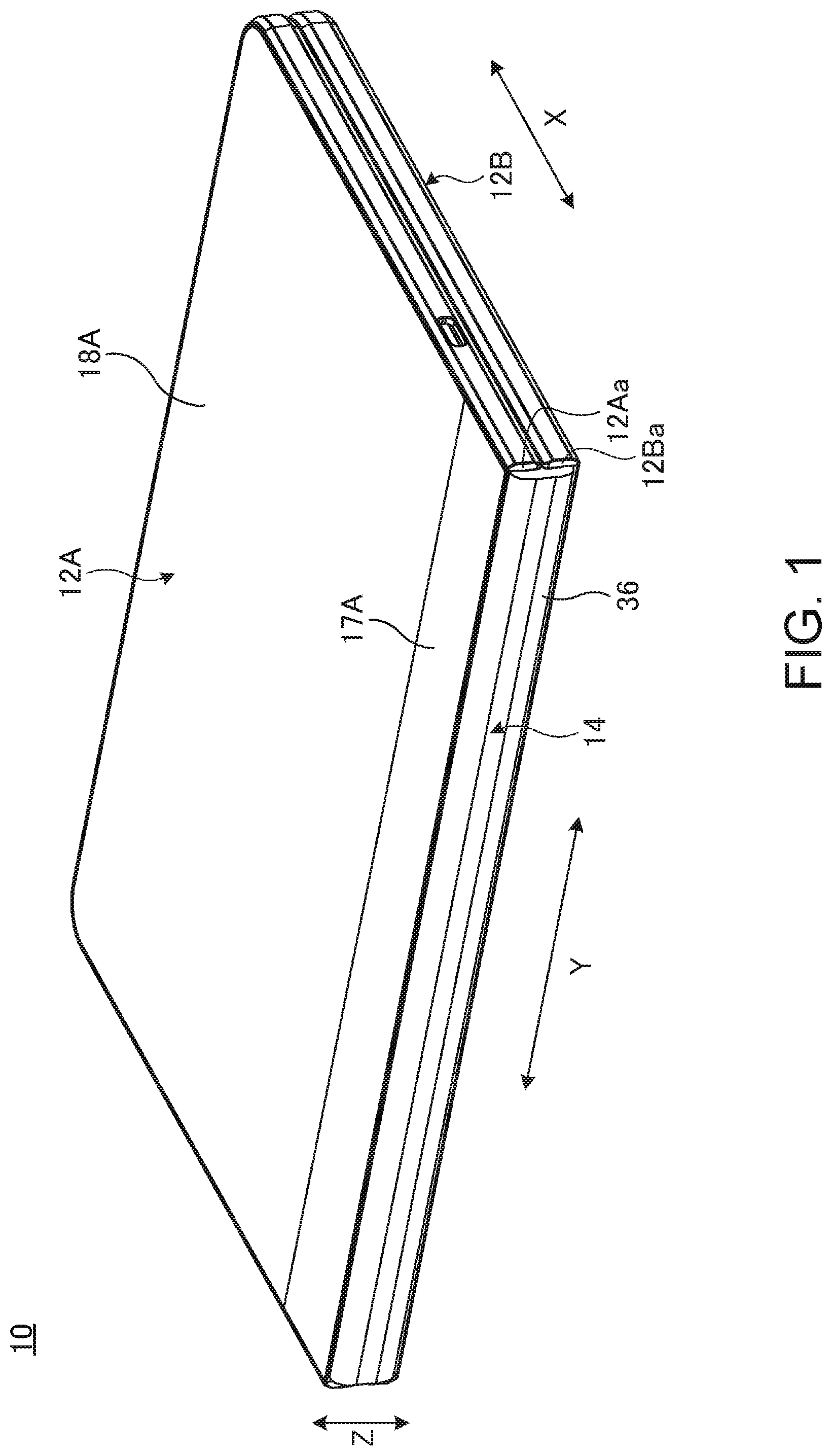
is a perspective view schematically illustrating one example of a state that an electronic apparatus according to one embodiment of the present invention is closed and is brought into a 0-degree posture.
is a perspective view schematically illustrating one example of a state that the electronic apparatus which is illustrated in is opened and is brought into a 180-degree posture.
is a plan view schematically illustrating one example of an internal structure of the electronic apparatus which is illustrated in .
is a schematic sectional diagram taken along the IV-IV line in .
is a schematic sectional diagram taken along the V-V line in .
is a schematic sectional diagram illustrating one example of a state that the electronic apparatus which is illustrated in is brought into the 0-degree posture.
is a schematic side sectional diagram illustrating one configuration example that a plate-side locking strip is directly locked with a hinge main body.
DETAILED DESCRIPTION
In the following, an electronic apparatus pertaining to the present invention will be described in detail by giving a preferred embodiment, while referring to the appended drawings.
is a perspective view schematically illustrating one example of a state that an electronic apparatus 10 according to one embodiment of the present invention is closed and brought into the 0-degree posture. is a perspective view schematically illustrating one example of a state that the electronic apparatus 10 which is illustrated in is opened and brought into the 180-degree posture. is a plan view schematically illustrating one example of the internal structure of the electronic apparatus 10 which is illustrated in .
As illustrated in to , the electronic apparatus 10 includes a first chassis 12 A and a second chassis 12 B, a hinge device 14 and a display 16 . The electronic apparatus 10 according to one embodiment exemplifies a tablet-type PC (Personal Computer) or a Laptop PC which is made foldable just like a book. The electronic apparatus 10 may be a smartphone, a portable gaming machine and so forth.
The respective chassis 12 A and 12 B are arranged in a mutually adjacent state. Each of the chassis 12 A and 12 B is appropriately loaded with various electronic components such as a CPU (Central Processing Unit)-implemented mother board, a battery device, an antenna module, a communication module and so forth.
The first chassis 12 A includes a frame member 17 A and a cover member 18 A. The frame member 17 A is a rectangular frame-shaped member that vertical walls are formed on three sides, other than one side that an adjacent end 12 Aa which is adjacent to the second chassis 12 B is formed. The cover member 18 A is a plate-shaped member which closes a rear-face opening in the frame member 17 A (also see ). Likewise, the second chassis 12 B includes a frame member 17 B that vertical walls are formed on three sides, other than one side that an adjacent end 12 Ba which is adjacent to the first chassis 12 A is formed and a cover member 18 B which closes a rear-face opening in the frame member 17 B. Front-face openings in the frame members 17 A and 17 B are closed with the display 16 .
Each of the members 17 A, 17 B, 18 A and 18 B is configured by a metal member which is made of, for example, stainless steel, magnesium, aluminum and so forth, a fiber-reinforced resin plate which contains reinforced fibers such as carbon fibers and other fibers and so forth.
The hinge device 14 connects the chassis 12 A and 12 B to be rotationally movable relative to each other between the 0-degree posture and the 180-degree posture. The hinge device 14 also functions as a back cover which hides a gap between the adjacent ends 12 Aa and 12 Bb which is formed at the time of taking the 0-degree posture which is illustrated in . The display 16 extends ranging from the chassis 12 A to the chassis 12 B.
In the following, the electronic apparatus 10 will be described by calling a direction that the chassis 12 A and the chassis 12 B are arranged side by side as an X direction, a direction which is orthogonal to the X direction and is oriented along the adjacent ends 12 Aa and 12 Bb of the chassis 12 A and 12 B as a Y direction and a thickness direction of the chassis 12 A and 12 B as a Z direction respectively. In addition, angular postures between the chassis 12 A and 12 B will be described by calling a state that the chassis 12 A and 12 B are folded to mutually overlap in a plane direction as the 0-degree posture (see ) and calling a state that the chassis 12 A and 12 B are mutually arrayed side by side in a direction (the X direction) which is vertical to the surface normal direction as the 180-degree posture (see and ). It is possible to call each posture that the chassis 12 A and 12 B take between 0 degree and 180 degrees by appropriately marking each angle. For example, a state that mutual surface normal directions of the chassis 12 A and 12 B are orthogonal to each other exhibits a 90-degree posture. The above-described degrees of angles are picked up for the convenience of description and such a situation that in an actual product, an angular position thereof slightly deviates from an accurate angular position that an angle value indicates would naturally occur.
is a schematic sectional diagram which is taken along the IV-IV line in . is a schematic sectional diagram which is taken along the V-V line in . is a schematic sectional diagram which illustrates one example of a state that the electronic apparatus 10 which is illustrated in is brought into the 0-degree posture.
In the 0-degree posture which is illustrated in and , the chassis 12 A and 12 B are brought into a state of being folded in two. The display 16 is a paper-like flexile display which is made of the organic EL. At the time of taking the 0-degree posture, the display 16 enters a state that a region R 1 on the first chassis 12 A side and a region R 2 on the second chassis 12 B side which are illustrated in are arranged to mutually confront and a folding region R 3 which is a boundary region between the regions R 1 and R 2 is folded in an arc. In the 180-degree posture which is illustrated in , the chassis 12 A and the chassis 12 B are mutually arranged side by side in a crosswise direction. In this case, since the regions R 1 and R 2 and the folding region R 3 are arranged side by side on an XY plane, the display 16 exhibits a planar shape, as a whole (also see and ).
In the display 16 , the region R 1 is fixed relative to the first chassis 12 A and the region R 2 is fixed relative to the second chassis 12 B. Specifically, a rear face 16 a of the display 16 in the region R 1 is fixed to the first chassis 12 A via a first plate 20 A and the rear face 16 a of the display 16 in the region R 2 is fixed to the second chassis 12 B via a second plate 20 B. The first plate 20 A is adjacent to a first support plate 22 A of the hinge device 14 and the second plate 20 B is adjacent to a second support plate 22 B of the hinge device 14 (see ).
As illustrated in to , the plates 20 A and 20 B are so arranged on the left and right sides as to sandwich the hinge device 14 and support the rear face 16 a of the display 16 with their front faces 20 Aa and 20 Ba respectively. On the rear face 16 a of the display 16 , the region R 1 is adhesively fixed to the front face 20 Aa of the first plate 20 A and the region R 2 is adhesively fixed to the front face 20 Ba of the second plate 20 B.
Each of the plates 20 A and 20 B is configured by, for example, a base plate 24 and a metal frame 25 . The base plate 24 is, for example, a carbon fiber reinforced resin plate that carbon fibers are impregnated with a matrix resin such as an epoxy resin and so forth. The metal frame 25 is made of, for example, a magnesium alloy and so forth and is fixed to an outer peripheral edge of a rear face 24 a of the base plate 24 .
Since the plates 20 A and 20 B are made of the carbon fiber reinforced resin, ensuring of a high flatness, thinning and right-weighting of the plates 20 A and 20 B are possible. However, regarding the carbon fiber reinforced resin, it is feared that the carbon fibers might fall off an outer peripheral end face (edge) as if powder is blown out and profiling, threading and so forth of the carbon fiber reinforced resin are difficult. Accordingly, each of the plates 20 A and 20 B is equipped with a metal frame 25 which is so installed as to surround outer edges of the outer peripheral end face thereof and the rear face 24 a of the base plate 24 . The plates 20 A and 20 B are fixed to the frame members 17 A and 17 B of the chassis 12 A and 12 B respectively by threading screws 27 into screw holes 26 which are formed in the metal frame 25 . The plates 20 A and 20 B may be formed by using metal materials and resin materials, in place of the carbon fiber reinforced resins. In this case, installation of the metal frame 25 may be omitted.
The folding region R 3 of the display 16 is made to be movable relative to the chassis 12 A and 12 B. At the time of taking the 180-degree posture, the rear face 16 a of the display 16 in the folding region R 3 is supported by the hinge main body 28 and the support plates 22 A and 22 B (see ). At the time of taking the 0-degree posture, the folding region R 3 is folded in the arc, a part of the rear face 16 a of the display 16 is supported by the support plates 22 A and 22 B and most of the rear face 16 a of the display 16 is separated from the hinge device 14 (see ).
As illustrated in to , the hinge device 14 in one embodiment of the present invention has a hinge main body 28 , the first support plate 22 A and the second support plate 22 B.
The hinge main body 28 is installed at a position that the hinge main body 28 strides over the adjacent ends 12 Aa and 12 Ba of the chassis 12 A and 12 B and extends over the almost full length in the Y direction along the adjacent ends 12 Aa and 12 Ba respectively. The hinge main body 28 is a block-shaped component which is made of a metal material such as aluminum and so forth. Two hinge shafts 14 A and 14 B which are arrayed in the X direction in the 180-degree posture are supported to the hinge main body 28 .
A first end of a first link arm 30 A is supported to the first hinge shaft 14 A to be rotatable axially. A first end of a second link arm 30 B is supported to the second hinge shaft 14 B to be rotatable axially. The link arms 30 A and 30 B have boomerang-like curved shapes which gradually come closer to inner faces 12 Ab and 12 Bb of the chassis 12 A and 12 B respectively toward a direction that the link arms 30 A and 30 B are separated from the hinge shafts 14 A and 14 B respectively.
A second end of the first link arm 30 A is connected to a first bracket 31 A to be relatively rotatable by using a rotation shaft 34 . The first bracket 31 A is fixed to the inner face 12 Ab of the first chassis 12 A by using a screw 27 and so forth. A second end of the second link arm 30 B is connected to a second bracket 31 B to be relatively rotatable by using a rotation shaft 35 . The second bracket 31 B is fixed to the inner face 12 Bb of the second chassis 12 B by using the screw 27 and so forth.
The link arms 30 A and 30 B and the brackets 31 A and 31 B are installed to be arrayed plurality along the Y direction which is a longitudinal direction of the hinge main body 28 (see ). Thereby, the hinge main body 28 connects the chassis 12 A and 12 B to be rotationally movable relative to each other. A gear mechanism for synchronizing mutual rotational moving operations of the chassis 12 A and 12 B, a torque mechanism for applying a predetermined rotational movement torque to the mutual rotational moving operations of the chassis 12 A and 12 B and so forth are also installed in the hinge main body 28 . As illustrated in and , a back cover component 36 which functions as a decorative cover is attached to a rear face of the hinge main body 28 .
At the time of taking the 180-degree posture which is illustrated in , the hinge main body 28 supports the rear face 16 a of the display 16 in the folding region R 3 with its own front face 28 a . On this occasion, the hinge main body 28 is housed in the chassis 12 A and 12 B and is so arranged as to stride over the mutually proximate or abutting adjacent ends 12 Aa and 12 Ba of the chassis 12 A and 12 B in the X direction. At the time of taking the 0-degree posture which is illustrated in , the hinge main body 28 is so arranged as to fill the gap between the widely separated adjacent ends 12 Aa and 12 Ba and functions as the back cover of the electronic apparatus 10 which is folded just like a book. On this occasion, the back cover component 36 is exposed to an outermost face and thereby prevents external appearance designability of the folded electronic apparatus 10 from being deteriorated (see ).
The support plates 22 A and 22 B are made of metal materials such as aluminum and so forth and are bisymmetric in shape. The support plates 22 A and 22 B are installed on the sides of the inner faces 12 Ab and 12 Bb of the chassis 12 A and 12 B respectively and extend along the adjacent ends 12 Aa and 12 Ba respectively over the almost full length of the electronic apparatus 10 in the Y direction.
The first support plate 22 A is arranged between the first plate 20 A and the hinge main body 28 . In the first support plate 22 A, an edge 22 Aa which is located on the side of the first plate 20 A is connected to the first bracket 31 A to be relatively rotatable via a rotating shaft 38 . In the first support plate 22 A, an edge (a boundary edge 22 Ab) which is located on the side of the hinge main body 28 is formed to be movable relative to the hinge main body 28 .
The second support plate 22 B is arranged between the second plate 20 B and the hinge main body 28 . In the second support plate 22 B, an edge 22 Ba which is located on the side of the second plate 20 B is connected to the second bracket 31 B to be relatively rotatable via a rotating shaft 39 . In the second support plate 22 B, an edge (a boundary edge 22 Bb) which is located on the side of the hinge main body 28 is formed to be movable relative to the hinge main body 28 .
The support plates 22 A and 22 B swing around the rotating shafts 38 and 39 which are set as rotation centers in accordance with the rotational moving operations of the chassis 12 A and 12 B respectively. At the time of taking the 180-degree posture, the support plates 22 A and 22 B support the rear face 16 a of the display 16 in the folding region R 3 with their front faces 22 Ac and 22 Bc respectively. At the time of taking an angular posture other than the 180-degree posture, the support plates 22 A and 22 B are brought into contact with the display 16 respectively in a state of leaving gaps between the display 16 and the support plate 22 A and between the display 16 and the support plate 22 B or by applying minute force of an extent of not inducing deformation of the display 16 (see ). The support plates 22 A and 22 B may be also configured to support the folding region R 3 of the display 16 also in an angular posture other than the 180-degree posture and to correct the shape of the folding region R 3 respectively. The support plates 22 A and 22 B stably support the folding region R 3 of the display 16 planarly in this way at the time of taking the 180-degree posture and, in addition, do not hinder the folding operation of the folding region R 3 respectively.
At the time of taking the 180-degree posture which is illustrated in and , it is desirable for edges of the plates 20 A and 20 B which are located on the sides of the support plates 22 A and 22 B respectively and the edges 22 Aa and 22 Ba of the support plates 22 A and 22 B to form one plane with no level difference. Likewise, it is also desirable to form one plane with no level difference between the boundary edge 22 Ab of the support plate 22 A and an edge 28 b of the hinge main body 28 and between the boundary edge 22 Bb of the support plate 22 B and an edge 28 c of the hinge main body 28 respectively.
In a case where the positions of the above-described respective edges deviate from one another in the Z direction and the level difference occurs between the front faces 20 Aa and 22 Ac, between the front faces 22 Ac and 28 a , between the front faces 28 a and 22 Bc or between the front faces 22 Bc and 20 Ba, the level difference affects the display 16 . Then, at the time of taking the 180-degree posture, the display 16 is curved or waves and product defects such as visual confirmation defects, display defects and so forth would possibly occur. In addition, in a case where the display 16 is curved or waves, the display 16 would not possibly work on an opening/closing track in design in opening and closing operations which are performed between the 180-degree posture and the 0-degree posture. Consequently, it is also feared that an excessive load would be exerted particularly on the folding region R 3 and its vicinity and thereby the display 16 would be damaged or would malfunction.
However, in the support plates 22 A and 22 B, the edge 22 Aa which is located on the side of the plate 20 A and the edge 22 Ba which is located on the side of the plate 20 B side are connected to the brackets 31 A and 31 B via the rotating shafts 38 and 39 respectively. Then, the brackets 31 A and 31 B are fixed to the chassis 12 A and 12 B respectively. Accordingly, the position of the first support plate 22 A relative to the first chassis 12 A is fixed and, also the first plate 20 A is fixed to the first chassis 12 A. Likewise, the position of the second support plate 22 B relative to the second chassis 12 B is fixed and, also the second plate 20 B is fixed to the second chassis 12 B. Accordingly, level differences other than a manufacturing tolerance do not occur between the front faces 20 Aa and 22 Ac and between the front faces 20 Ba and 22 Bc and any level difference is not formed substantially.
Accordingly, the electronic apparatus 10 according to one embodiment of the present invention includes constitutional elements for suppressing the level differences between the front face 22 Ac of the support plate 22 A and the front face 28 a of the hinge main body 28 and between the front face 22 Bc of the support plate 22 B and the front face 28 a of the hinge main body 28 . Specifically, the electronic apparatus 10 includes a first locking strip 40 A, a second locking strip 40 B, a first plate-side locking strip 41 A and a second plate-side locking strip 41 B.
As illustrated in , the first locking strip 40 A of the hinge main body 28 is a claw-shaped member which is formed on the edge 28 b which is located on the side of the first support plate 22 A. The first locking strip 40 A protrudes toward the side of the first support plate 22 A beyond a boundary line between the hinge main body 28 and the first support plate 22 A. The front face of the first locking strip 40 A is locked to the rear face of the first support plate 22 A at the time of taking the 180-degree posture. On this occasion, the boundary edge 22 Ab of the first support plate 22 A is so arranged as to be sandwiched between the first locking strip 40 A and the display 16 .
The second locking strip 40 B is a claw-shaped member which is formed on the edge 28 c of the hinge main body 28 which is located on the side of the second support plate 22 B. The second locking strip 40 B protrudes toward the side of the second support plate 22 B beyond a boundary line between the hinge main body 28 and the second support plate 22 B. The front face of the second locking strip 40 B is locked to the rear face of the second support plate 22 B at the time of taking the 180-degree posture. On this occasion, the boundary edge 22 Bb of the second support plate 22 B is so arranged as to be sandwiched between the second locking strip 40 B and the display 16 .
A protrusion length of each of the locking strips 40 A and 40 B is, for example, about 2 mm. Tapered faces 42 are formed on the front faces of the locking strips 40 A and 40 B, that is, the faces which abut on the support plates 22 A and 22 B respectively. In addition, also tapered faces 43 are formed on rear faces 22 Ad and 22 Bb of the boundary edges 22 Ab and 22 Bb of the support plates 22 A and 22 B respectively at positions that the tapered faces 42 abut.
The tapered faces 42 are inclined faces which incline in a downward direction that the tapered faces 42 gradually separate from the front face 28 a of the hinge main body 28 toward protrusion tips of the locking strips 40 A and 40 B respectively. The tapered faces 43 are inclined faces which incline in a downward direction that the tapered faces 43 gradually separate from the front faces 22 Ac and 22 Bc of the support plates 22 A and 22 B toward directions that the locking strips 40 A and 40 B protrude respectively. Thereby, in a case where the support plates 22 A and 22 B relatively move while rotating relative to the hinge main body 28 at the time that the chassis 12 A and 12 B mutually perform rotational moving operations, that the locking strips 40 A and 40 B get caught on the support plates 22 A and 22 B respectively is suppressed and smooth swinging operations of the support plates 22 A and 22 B are secured.
In and , a reference numeral 44 denotes slope members which protrude from edges of the support plates 20 A and 20 B which are located on the sides of the support plate 22 A and the support plate 22 B respectively. The slope members 44 are installed in such a manner that a plurality (for example, four) of the slope members 44 is arrayed along the edges 22 Aa and 22 Ba respectively. The slope members 44 are adapted to support sliding to the rear face 16 a of the display 16 at the time of performing the mutual rotational operations for shifting from the 180-degree posture to the 0-degree posture thereby to correct the shape of the folding region R 3 to an appropriate shape (a linear shape, a curved shape and so forth) which accords with a rotational movement angle. Recessed escaping parts for avoiding interference of the slope member 44 at the time of taking the 180-degree posture are formed in the boundary edges 22 Ab and 22 Bb of the support plates 22 A and 22 B respectively.
As illustrated in , the first plate-side locking strip 41 A is a claw-shaped member which is formed on the rear face 22 Ad of the boundary edge 22 Ab of the first support plate 22 A. The first plate-side locking strip 41 A has, for example, a hook shape in section and protrudes toward the side of the hinge main body 28 beyond a boundary line between the first support plate 22 A and the hinge main body 28 . The first plate-side locking strip 41 A is locked on the rear face side of the hinge main body 28 at the time of taking the 180-degree posture.
The first plate-side locking strip 41 A in one embodiment of the present invention enters an X-direction slot 30 Aa which is formed in a first link arm 30 A and is locked to a rear face 30 Ab of the first link arm 30 A. That is, the first link arm 30 A is so connected to the hinge main body 28 as to be relatively rotatable via the first hinge shaft 14 A and movement of the first link arm 30 A is restrained at a position that that the first link arm 30 A rotates the most in a clockwise direction in at the time of taking the 180-degree posture. Accordingly, the first plate-side locking strip 41 A is relatively locked on the side of a rear face 28 d of the hinge main body 28 by being locked to the first link arm 30 A and further upward movement of the first plate-side locking strip 41 A is restrained.
As illustrated in , the second plate-side locking strip 41 B is a claw-shaped member which is formed on the rear face 22 Bd of the boundary edge 22 Bb of the second support plate 22 B. The second plate-side locking strip 41 B has, for example, a hook shape in section and protrudes toward the side of the hinge main body 28 beyond a boundary line between the second support plate 22 B and the hinge main body 28 . The second plate-side locking strip 41 B is locked on the side of the rear face 28 d of the hinge main body 28 at the time of taking the 180-degree posture.
The second plate-side locking strip 41 B in one embodiment of the present invention also enters an X-direction slot 30 Ba which is formed in a second link arm 30 B and is locked to a rear face 30 Bb of the second link arm 30 B. That is, the second link arm 30 B is connected to the hinge main body 28 to be relatively rotatable via the second hinge shaft 14 B and movement of the second link arm 30 B is restrained at a position that the second link arm 30 B rotates the most in a counter-clockwise direction in at the time of taking the 180-degree posture. Accordingly, the second plate-side locking strip 41 B is relatively locked on the side of the rear face side 28 d of the hinge main body 28 by being locked to the second link arm 30 B and further upward movement of the second plate side locking strip 41 B is restrained.
A protrusion length of each of the plate-side locking strips 41 A and 41 B is, for example, about 2 mm. Incidentally, the front faces of the plate-side locking strips 41 A and 41 B may be made flat with no formation of such tapered faces as those on the locking strips 40 A and 40 B. The reason therefore lies in the point that at the time that the chassis 12 A and 12 B mutually perform the rotational moving operations, the plate-side locking 41 A and 41 B simply move in directions that the plate-side locking strips 41 A and 41 B come into contact with the rear faces 30 Ab and 30 Bb and separate from the rear faces 30 Ab and 30 Bb respectively and complicated relative rotation and relative movement that the support plates 22 A and 22 B perform relative to the hinge main body 28 are not performed.
As illustrated in , the plate-side locking strips 41 A and 41 B may be structured to be directly locked on the side of the rear face 28 d of the hinge main body 28 instead of being locked via the link arms 30 A and 30 B respectively.
Incidentally, although in , only the second plate-side locking strip 41 B and peripheral parts thereof are illustrated, also the first plate-side locking strip 41 A and peripheral parts thereof may be structured to be laterally symmetric to the structure which is illustrated in .
As illustrated in , the first locking strip 40 A and the first plate-side locking strip 41 A are so arranged as to alternate with each other in the Y direction. Likewise, the second locking strip 40 B and the second plate-side locking strip 41 B are so arranged as to alternate with each other in the Y direction. Further, in one embodiment of the present invention, a set of the locking strips 40 A and 40 B and the plate-side locking strips 41 A and 41 B is installed such that a plurality of sets, for example, four sets of the locking strips 40 A and 40 B and the plate-side locking strips 41 A and 41 B are arrayed side by side along the Y direction respectively.
Next, the rotational moving operations of the chassis 12 A and 12 B and operational effects which are obtained in a case where the chassis 12 A and 12 B are rotationally moved will be described.
First, at the time of taking the 0-degree posture which is illustrated in , the chassis 12 A and 12 B exhibit a highly designable folded state that the chassis 12 A and 12 B are folded, with surface normal directions thereof being almost in parallel with each other. In this state, the display 16 exhibits a bell shape that the folding region R 3 is curved with a desirable curvature. That is, in the display 16 , the folding region R 3 is folded to the desired bell shape by the plates 20 A and 20 B which are folded in parallel with each other via a predetermined gap. As a result, in the electronic apparatus 10 , the chassis 12 A and 12 B are thinned to the greatest possible extent and, in addition, also breakage of the display 16 which would occur at the time of folding the display 16 is suppressed.
Next, a case where the chassis 12 A and 12 B are mutually rotationally moved from the 0-degree posture toward the 180-degree posture will be described. As illustrated in to , in this case, the support plates 22 A and 22 B move relative to the hinge main body 28 while swinging around the rotating shafts 38 and 39 respectively in association with mutual opening operations of the chassis 12 A and 12 B. The folded state of the folding region R 3 of the display 16 is gradually released with the aid of the plates 20 A and 20 B which operate integrally with the chassis 12 A and 12 B respectively.
Then, in the 180-degree posture which is illustrated in and , the plates 20 A and 20 B, the hinge main body 28 and the support plates 22 A and 22 B lie on the same X-Y plane respectively. The front faces 20 Aa and 20 Ba of the plates 20 A and 20 B, the front face 28 a of the hinge main body 28 and the front faces 22 Ac and 22 Bc of the support plates 22 A and 22 B are arranged to be almost flush with one another and as a whole form one flat plate. The entire of the rear face 16 a of the display 16 is supported on the flat plate and the display 16 forms one plate-shaped large screen (also see ).
Next, a case where the chassis 12 A and 12 B are mutually moved rotationally from the 180-degree posture toward the 0-degree posture will be described. In this case, in association with mutual closing operations of the chassis 12 A and 12 B, the support plates 22 A and 22 B again swing and move relative to the hinge main body 28 . The display 16 receives folding force which is exerted from the plates 20 A and 20 B which operate integrally with the chassis 22 A and 22 B respectively and the folding region R 3 is gradually folded. As a result, the folding region R 3 exhibits again the almost bell shape in the 0-degree posture which is illustrated in .
In association with such rotational moving operations as above, in the 180-degree posture which is illustrated in , the locking strips 40 A and 40 B are locked to the rear faces 22 Ad and 22 Bd of the support plates 22 A and 22 B respectively. Further, as illustrated in , the plate-side locking strips 41 A and 41 B are indirectly locked to the rear face 28 d of the hinge main body 28 via the link arms 30 A and 30 B respectively. Incidentally, at the time of taking the 0-degree posture which is illustrated in , the locking strips 40 A and 40 B are released from the support plates 22 A and 22 B respectively and also the plate-side locking strips 41 A and 41 B are released from the link arms 30 A and 30 B respectively.
In a case where the chassis 12 A and 12 B are mutually operated from the 0-degree posture to the 180-degree posture in this way, the respective locking strips 40 A and 40 B are locked to their confronting support plates 22 A and 22 B and push the rear faces 22 Ad and 22 Bd of the support plates 22 A and 22 B upward respectively. Likewise, the plate-side locking strips 41 A and 41 B which are arranged alternately with the respective locking strips 40 A and 40 B are locked to their confronting link arms 30 A and 30 B which are connected to the hinge main body 28 respectively and push the hinge main body 28 upward.
Thereby, at a boundary part between the hinge main body 28 and the first support plate 22 A, force that the first locking strip 40 A pushes the first support plate 22 A upward and force that the first plate-side locking strip 41 A pushes the first link arm 30 A and the hinge main body 28 upward regulate mutually. As a result, in the hinge main body 28 and the first support plate 22 A, their edges 28 b and 22 Ab induce no level difference in the Z direction and their front faces 28 a and 22 Ac are arranged on the same plane and thereby the main hinge body 28 and the first support plate 22 A are stabilized.
Likewise, also at a boundary part between the hinge main body 28 and the second support plate 22 B, force that the second locking strip 40 b pushes the second support plate 22 B upward and force that the second plate-side locking strip 41 B pushes the second link arm 3 B and the hinge main body 28 upward regulate each other. As a result, in the hinge main body 28 and the second support plate 22 B, their edges 28 c and 22 Bb induce no level difference in the Z direction and their front faces 28 a and 22 Bc are arranged on the same plane and thereby the hinge main body 28 and the second support plate 22 B are stabilized.
Incidentally, as described above, since the mutual relative positions of the support plates 22 A and 22 B and the plates 20 A and 20 B are fixed, no level difference occurs between/among these plates.
Accordingly, in the electronic apparatus 10 , in the 180-degree posture, the front faces 20 Aa, 20 Ba, 28 a , 22 Ac, 22 Bc which support the display 16 stably form one plane. Therefore, it becomes possible for the electronic apparatus 10 to stably support the display 16 at the time of taking the 180-degree posture and to suppress occurrence of deformation, defects in good and so forth of the display 16 .
In the electronic apparatus 10 , at the time of taking the 180-degree posture, the boundary edge 22 Ab of the first support plate 22 A is so arranged as to be sandwiched between the first locking strip 40 A and the display 16 . In addition, also the boundary edge 22 Bb of the second support plate 22 B is so arranged as to be sandwiched between the second locking strip 40 B and the display 16 . Accordingly, as illustrated in , although the electronic apparatus 10 has a configuration that the locking strips 40 A and 40 B are installed, it becomes possible to secure smooth operations of the support plates 22 A and 22 B and a high flatness of the front faces 28 a , 22 Ac and 22 Bc simply by securing small gaps between the front face 28 a and the front face 22 Ac and between the front face 28 a and the front face 22 Bc.
In the electronic apparatus 10 , the plate-side locking strips 41 A and 41 B abut on the link arms 30 A and 30 B respectively at the time of taking the 180-degree posture and thereby are locked to the hinge main body 28 relatively. Thereby, it becomes possible for the electronic apparatus 10 to make the link arms 30 A and 30 B surely rotationally move to appropriate positions relative to the hinge main body 28 and to press the link arms 30 A and 30 B against the hinge main body 28 with the aid of the plate-side locking strips 41 A and 41 B. As a result, in a case where the electronic apparatus 10 is used in the 180-degree posture, it becomes possible to suppress occurrence of backlash between the hinge main body 28 and the link arm 30 A and between the hinge main body 28 and the link arm 30 B.
In the electronic apparatus 10 , the plurality of sets of the locking strips 40 A and 40 B and the plate-side locking strips 41 A and 41 B which are alternately arranged is provided to be arrayed along the Y direction respectively. Accordingly, it becomes possible to suppress occurrence of the level differences between the hinge main body 28 and the support plate 22 A and between the hinge main body 28 and the support plate 22 B longitudinally. Incidentally, in regard to the number of sets of the first locking strip 40 A and the first plate-side locking strip 41 A and the number of sets of the second locking strip 40 B and the second plate-side locking strip 41 B, at least each one set may be prepared.
Incidentally, the present invention is not limited to the above-described embodiment and it goes without saying that it is possible to freely change the configuration within a range not deviating from the gist of the present invention.
Although, in the above description, the electronic apparatus 10 which is foldable in half just like the book is exemplified, the present invention is also applicable to various configurations such as, for example, an outward-opening type configuration that a small chassis is so connected to each of left and right edges of a large chassis as to be foldable, an S-type folding configuration that chassis which are different in folding direction are connected to right and left edges of one chassis, a J-type folding configuration that a small chassis is so connected to one of left and right edges of a large chassis as to be foldable and so forth and the number of the chassis to be connected may be set to four or more.
Although the disclosure has been described with respect to only a limited number of embodiments, those skilled in the art, having benefit of this disclosure, will appreciate that various other embodiments may be devised without departing from the scope of the present invention. Accordingly, the scope of the invention should be limited only by the attached claims.
DESCRIPTION OF SYMBOLS
•
• 10 : electronic apparatus • 12 A: first chassis • 12 B: second chassis • 14 : hinge device • 16 : display • 20 A: first plate • 20 B: second plate • 22 A: first support plate • 22 B: second support plate • 28 : hinge main body • 30 A: first link arm • 30 B: second link arm • 31 A: first bracket • 31 B: second bracket • 40 A: first locking strip • 40 B: second locking strip • 41 A: first plate-side locking strip • 41 B: second plate-side locking strip
Figures (6)
Citations
This patent cites (8)
- US2021/0307186
- US2022/0104370
- US2023/0229203
- US2024/0219967
- US2012190491
- US6453413
- US2020053001
- US2021102979