Abstract
A rockfall barrier for installation between an uphill side and a downhill side of a hill slope, with at least two guide devices for a net comprising an upper edge and a lower edge, and with an upper load-bearing rope, which guides the upper edge on the guide devices At least one middle rope is provided, which extends from an upper end point fixed to the upper load-bearing rope to a lower end point fixable at the hill slope.
Claims (17)
1. A rockfall barrier for installation between an uphill side and a downhill side of a hill slope, the rockfall barrier comprising: at least two guide devices for a net having an upper edge and a lower edge, and an upper load-bearing rope configured to guide the upper edge at the guide devices, wherein at least one middle rope is provided, the at least one middle rope extending from an upper end point fixed at the upper load-bearing rope to a lower end point configured to be fixed to the hill slope, wherein each at least one middle rope is directly coupled to a respective braking element configured to be fixed to the hill slope and arranged adjacent to the lower edge of the net.
17. A rockfall barrier, comprising: a net having an upper edge disposed at an uphill side of a hill slope and a lower edge disposed at a downhill side of the hill slope; at least two supports configured to guide the net; and an upper load-bearing rope guiding the upper edge at the at least two supports; wherein at least one middle rope extends from an upper end point fixed at the upper load-bearing rope to a lower end point fixed to the hill slope; wherein each at least one middle rope is directly coupled to a respective braking element fixed to the hill slope and arranged adjacent to the lower edge of the net.
Show 15 dependent claims
2. The rockfall barrier according to claim 1 , wherein two of the middle ropes are provided.
3. The rockfall barrier according to claim 1 , wherein the at least two guide devices are formed as supports arranged adjacent to each other.
4. The rockfall barrier according to claim 1 , wherein an upper end point of an associated load-bearing rope is fixed at a fixing point of the respectively associated guide device, the load-bearing rope extends from the upper end point to a lower end point configured to be fixed at the hill slope, and wherein associated braking elements are respectively arranged adjacent to the lower edge of the net.
5. The rockfall barrier according to claim 1 , wherein the at least two guide devices are configured to be fixed at the hill slope via hill side restraining ropes engaging at the respective fixing points.
6. The rockfall barrier according to claim 1 , wherein outermost guide devices of the at least two guide devices are configured to be fixed at the hill slope via a rope bracing engaging the respective fixing point.
7. The rockfall barrier according to claim 1 , wherein the upper end point of the middle rope is attached to the upper load-bearing rope via a rope connection.
8. The rockfall barrier according to claim 7 , wherein the rope connections are formed as T-shaped connections.
9. The rockfall barrier according to claim 7 , wherein the rope connections are formed as movable components.
10. The rockfall barrier according to claim 1 , wherein the lower edge of the net is guided via a lower net edge rope.
11. The rockfall barrier according to claim 10 , wherein the lower net edge rope extends at least approximately parallel to the upper load-bearing rope in the region of the net.
12. The rockfall barrier according to claim 10 , wherein the lower net edge rope is configured to be fixed at the hill slope via at least one braking element and at each rope end via an associated side anchor.
13. The rockfall barrier according to claim 10 , wherein a lower load-bearing rope extends at a distance from the net edge rope and that the middle rope or ropes is/are guided at the lower load-bearing rope via rope guide elements.
14. The rockfall barrier according to claim 1 , wherein an anchor is provided respectively for fixing the middle rope or the middle ropes at the hill slope.
15. The rockfall barrier of claim 1 , wherein each of the braking elements is disposed in line with a long axis of the respective middle rope.
16. The rockfall barrier of claim 1 , wherein the upper edge of the net is configured to be disposed uphill with respect to the lower edge of the net.
Full Description
Show full text →
FIELD
The present disclosure relates to a rockfall barrier.
INTRODUCTION
Such a rockfall barrier is known from EP 2 489 785 B1. The advantage of this rockfall barrier is to be seen in the fact that, on the one hand, it is possible to absorb high energy in the net and, on the other hand, it is also possible to transport the collected material from the support area to more easily accessible areas lying below the supports.
In the common rockfall barrier, the braking elements required to absorb the high energy are mostly located in the area of the supports. This makes maintenance and repair work more complex, especially when the common rockfall barrier is installed in terrain that is difficult to access.
SUMMARY
It is therefore the object of the present disclosure to provide a rockfall barrier of the type indicated in the preamble of claim 1 , which is also suitable for absorbing high energy in the net, while at the same time facilitating maintenance and repair work, in particular at braking elements.
The rockfall barrier according to the present disclosure for installation between an uphill side and a downhill side of a hill slope comprises, at least two guide devices, a net with an upper and a lower edge, an upper load-bearing rope, which guides the upper edge of the net at the guide devices, and at least one middle rope. This middle rope extends from an upper end point fixed to the upper load-bearing rope to a lower end point, which is fixable at the hill slope.
Advantageously, the rockfall barrier according to the present disclosure can be provided with only one upper load-bearing rope. Alternatively, however, it is also possible to provide several such upper load-bearing ropes, in particular to bundle them, if this is necessary due to the loads to be expected. Furthermore, the rockfall barrier according to the present disclosure does not comprise any horizontal middle ropes, which would possibly retain blocks to be caught in the upper area or would again increase the maintenance and repair effort, since such horizontal middle ropes also have to be provided with braking elements.
In contrast, the arrangement of the middle rope of the rockfall barrier according to the present disclosure has the advantage that it can guide the collected stone or boulder downwards.
As a possible alternative, it can be provided that the at least one middle rope is also guided diagonally or obliquely through the hit field in the area of the net. For this purpose, the middle rope can be arranged from an upper end point fixed to the upper load-bearing rope to a lower end point fixed at the hill slope. Also in this embodiment, the at least one middle rope can be provided with a braking element fixable at the hill slope and arranged adjacent to the lower edge of the net.
The connection of the middle rope with the net can be formed by looping it through the net, or by abutting it on the hill facing side at the top or on the side facing away from the hill. In this case, the middle rope is preferably connected to the net via connecting elements such as shackles or sewing ropes.
Advantageously, the at least one middle rope is provided with a braking element fixable at the hill slope and arranged adjacent to the lower edge of the net.
This advantageously ensures not only that the collected material can be conveyed from the support area (area with supports) to more easily accessible areas below the supports, but also that the braking element is located in these more easily accessible areas, which considerably facilitates necessary maintenance and repair work, especially after an impact. The dependent claims relate to advantageous further developments of the present disclosure.
In another particularly preferred embodiment, the rockfall barrier according to the present disclosure comprises two middle ropes, which can each be provided with an associated braking element, which are arranged adjacent to the lower edge of the net.
For fixing the at least one middle rope, an anchor can be provided, which is fixable at the hill slope.
If several middle ropes, in particular two middle ropes, are provided, each of these middle ropes can be fixed with an associated anchor at the hill slope.
BRIEF DESCRIPTION OF THE DRAWINGS
Further details, features and advantages of the present disclosure will be apparent from the following description of embodiments based on the drawing:
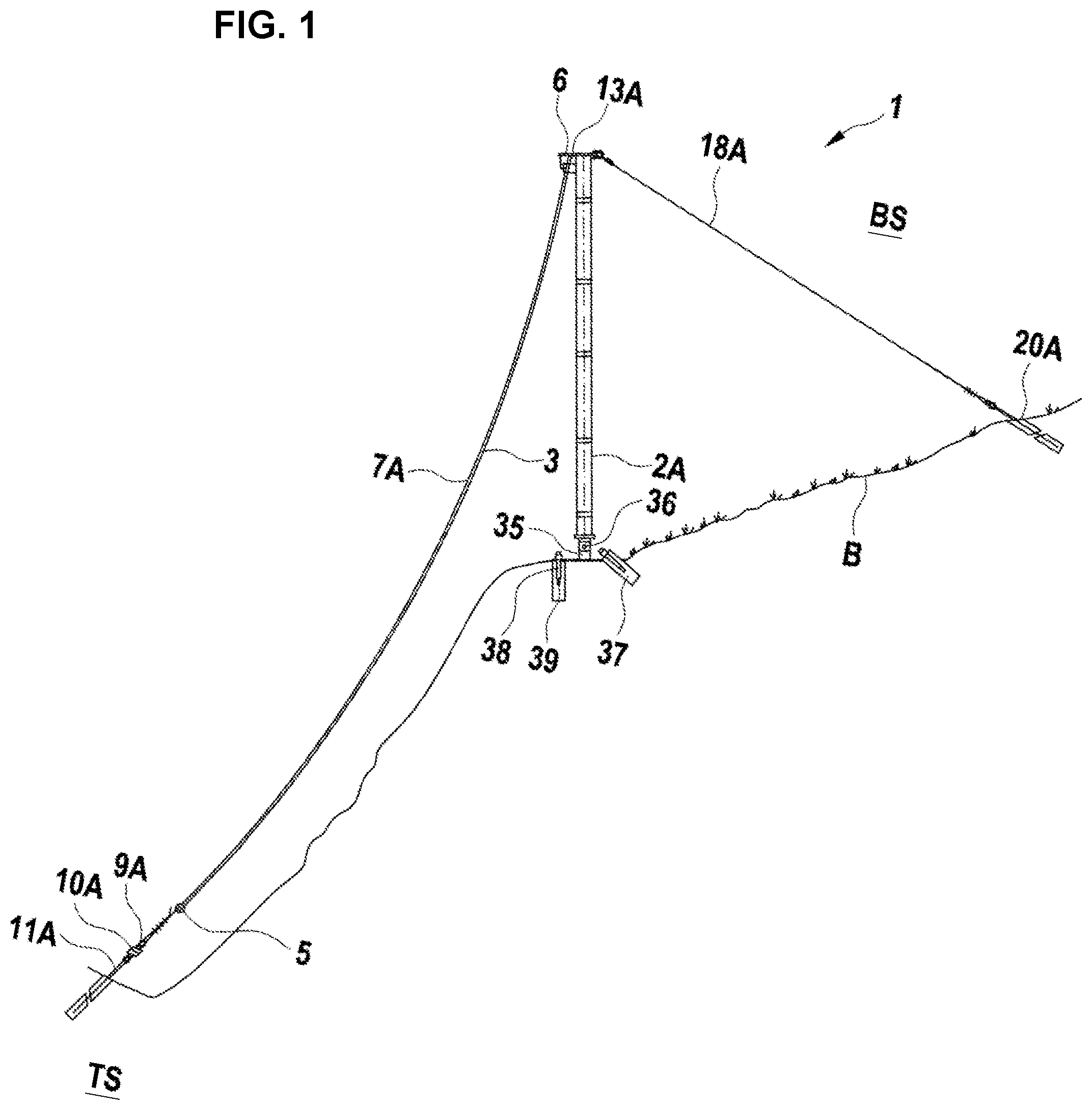
shows a schematic, slightly simplified side view of a rockfall barrier according to the present disclosure,
shows a top view or a plan view of the rockfall barrier according to ,
shows a representation of a first variant of the rockfall barrier according to the present disclosure corresponding to , and
shows a representation of a second variant of the rockfall barrier according to the present disclosure corresponding to .
DETAILED DESCRIPTION
shows a rockfall barrier 1 for installation between an uphill side BS and a downhill side TS of a hill slope B.
This rockfall barrier 1 comprises at least two guide devices, of which only one guide device 2 A is visible due to the illustration chosen in . However, the illustration in shows that in the example case shown in this figure, a total of five such guide devices can be provided in the form of supports 2 A, 2 B, 2 C, 2 D and 2 E. However, in order to be able to tension a net 3 , which is a further component of the rockfall barrier 1 according to the present disclosure, at least two guide devices or supports 2 A and 2 B must be provided. Of course, it is possible that more than five such guide devices or supports may be provided, depending on the size of the area to be protected by the rockfall barrier.
As an alternative to such supports, it is possible to tension the net 3 , for example, in a terrain gully, in particular in the form of a stream or river bed, in which case no supports are required, as the net 3 can be fixed to the edges delimiting the terrain gully (channel-shaped terrain form).
Another alternative for supports could be two walls, especially in the form of ferroconcrete walls or similar, which are provided anyway, for example, on a mountain road for other purposes.
As can be seen from a combined view of , the net 3 comprises an upper edge 4 and a lower edge 5 , which extends at a corresponding distance from the upper edge 4 depending on the size of the net 3 .
The rockfall barrier 1 according to the present disclosure further comprises an upper load-bearing rope 6 , which guides the upper edge 4 on the at least two guide devices, in particular the five guide devices 2 A to 2 E provided according to .
According to the present disclosure, at least one middle rope 7 A is also provided, which extends from an upper end point 8 A fixed to the upper load-bearing rope 6 to a lower end point 9 A fixable at the hill slope B.
further illustrates that the rockfall barrier 1 according to the present disclosure further comprises at least one braking element 10 A, which is arranged adjacent to the lower edge 5 of the net 3 and is fixable at the hill slope, for example, via an anchor 11 A, wherein shows the installation state of the rockfall barrier 1 according to the present disclosure, in which the fixing by the anchor 11 A at the hill slope B is carried out at the downhill side.
A combined view of further illustrates that the support 2 A is secured to the hill slope B by two hill side restraint ropes 18 A, 18 A′ via two hill side anchors 21 A, 21 A′.
As further shows, the support 2 A comprises a column head 13 A, through which the upper load-bearing rope 6 is guided.
At the lower end, the support 2 A is provided with a bolt 36 with spring cotter pin and a bottom plate 35 . The bottom plate 35 is fixed at the hill slope B by a tension pile 37 , a micropile tube 38 and a compression pile 39 .
As previously explained with reference to , at least two guide devices are required to tension the net 3 , which in the particularly preferred embodiment shown in are formed as supports 2 A and 2 B. As explained, however, in the example case five such supports 2 A to 2 E are provided, which are respectively arranged at a distance from each other. The construction, arrangement and securing or installation of these supports 2 A to 2 E is the same for each of the supports shown, so that in the following reference is made to supports 2 A and 2 B as representative of all supports 2 A to 2 E.
The support 2 A is connected with a load-bearing rope 12 A. This load-bearing rope comprises an upper end point 14 A, which is fixed to the support 2 A. The load-bearing rope 12 A further comprises a lower end point 15 A, which is connected with a braking element 16 A and which is fixable at the hill slope B via an anchor 17 A.
A corresponding arrangement comprises the support 2 B, which can also be fixed at the hill slope B via a load-bearing rope 12 B with upper end point 14 B and lower end point 15 B as well as braking element 16 B and anchor 17 B.
In the example, two middle ropes 7 A and 7 B extend between the load-bearing ropes 12 A and 12 B, which are called middle ropes, because they are arranged in a middle area between the load-bearing ropes 12 A and 12 B.
The two middle ropes 7 A and 7 B comprise upper end points 8 A and 8 B and lower end points 9 A and 9 B. The upper end points 8 A and 8 B are attached to the upper load-bearing rope 6 via rope connections 22 A and 22 B respectively. The rope connections 22 A and 22 B can, for example, be formed as T-shaped connections, which are preferably movable components.
The middle ropes 7 A and 7 B further comprise braking elements 10 A and 10 B arranged adjacent to the lower edge 5 of the net 3 , to which the lower end points 9 A and 9 B are fixed. The fixing of the braking elements and thus the fixing of the lower end points 9 A and 9 B of the middle ropes 7 A and 7 B is carried out by anchors 11 A and 11 B.
Thus, all braking elements 10 A, 10 B of the middle ropes 7 A, 7 B and 16 A as well as 16 B of the load-bearing ropes 12 A and 12 B are arranged adjacent to the lower edge 5 of the net 3 , wherein the lower edge 5 , as illustrates, is associated with an easily accessible area of the hill slope B, so that both stones or boulders, which have been transported into this easily accessible area by means of the middle ropes 7 A and 7 B can be removed easily and without danger from the net 3 and maintenance work, in particular repair work on the braking elements, can also be carried out easily and safely.
also shows that the upper load-bearing rope 6 can be fixed at the sides of the two outermost supports 2 A and 2 E respectively at the hill slope B via side anchors 20 A and 20 E. Furthermore, a side bracing 19 A and 19 E is provided in the area of these outermost supports 2 A and 2 E respectively. Both the ends of the upper load-bearing rope 6 and the side bracings 19 A and 19 E are fixable via side anchors 20 A and 20 E at the hill slope B.
Should it be necessary due to particularly high expected energy, braking elements can also be provided in the area of these side anchors 20 A and 20 E.
The rope connections 22 A and 22 B can, as explained above, be either movable along the load-bearing rope axis of the upper load-bearing rope 6 or also formed in a fixed manner. As also explained previously, the particularly preferred embodiment shown in comprises a total of five supports 2 A to 2 E.
Furthermore, middle ropes 7 A′, 7 B′ are provided between the load-bearing ropes associated with supports 2 B and 2 C, middle ropes 7 A″ and 7 B″ between the load-bearing ropes associated with supports 2 C and 2 D, and middle ropes 7 A′″ and 7 B′″ between the load-bearing ropes associated with supports 2 D and 2 E. With regard to their arrangement, extension and fixing, reference can be made to the above description of the middle ropes 7 A and 7 B, since in this respect both the supports 2 A to 2 E and the respective middle ropes are formed, arranged and fixed identically.
This also applies to the hill side restraint ropes, which have already been explained by means of the restraint ropes 18 A, 18 A′ and 18 B for the supports 2 A and 2 B as examples for all supports 2 A to 2 E.
The embodiment of the rockfall barrier 1 according to the present disclosure as shown in differs from that shown in only in the arrangement of a lower net edge rope 28 , by which the lower edge 5 of the net 3 is guided. This lower net edge rope 28 extends through the entire lower edge 5 and is secured and tensioned on both sides of the net 3 via braking elements 24 or 25 and anchors 26 or 27 at the hill slope B. The upper load-bearing rope 6 , the load-bearing ropes of the supports 2 A to 2 E, the middle ropes, and the lower net edge rope 28 are preferably looped through or threaded into the net 3 .
With regard to all other components of the embodiment of the rockfall barrier 1 according to , reference can be made to the explanations on .
This also applies to the embodiment of the rockfall barrier 1 according to , in which, as in the embodiment according to , the lower edge 5 of the net 3 is guided via a net edge rope 28 , which can be fixable on both sides of the net 3 via braking elements 29 and 31 as well as anchors 30 and 32 at the hill slope B. The lower load-bearing rope 23 of this embodiment is arranged at a distance A from the net edge rope 28 and is fixed to the hill slope B on both sides via braking elements 24 and 25 as well as anchors 26 and 27 . As shows, this has the advantage that only the load-bearing ropes 12 A and 12 B need to be fixed to the hill slope B via anchors 17 A and 17 B, while the middle ropes 7 A and 7 B can be fixed to the lower load-bearing rope 23 via rope guides 33 and 34 . Preferably, this fixing can be formed movably along the axis of the lower load-bearing rope 23 . It is also possible that a plurality of such load-bearing ropes are provided, for example combined as a bundle.
Furthermore, there is the advantage that the braking elements of the load-bearing ropes 12 A and 12 B as well as the middle ropes 7 A and 7 B can easily extend in the area created by the distance A, if this is necessary due to the impact of one or more boulders into the net 3 .
As stated, reference may be made to the description of the preceding embodiments with respect to the construction of the arrangement and the fixing of the components of the rockfall barrier 1 as shown in .
In addition to the foregoing written disclosure of the present disclosure, explicit reference is hereby made to the graphic representation of the present disclosure in to 4 .
REFERENCE SIGN LIST
•
• 1 rockfall barrier • 2 A to 2 E guide devices/supports • 3 net • 4 upper edge • 5 lower edge • 6 upper load-bearing rope • 7 A, 7 B middle rope • 8 A, 9 A end points • 10 A, 10 B, 16 A, 16 B, 24 , 25 , 29 , 31 braking elements • 11 A, 11 B, 17 A, 17 B, 20 A, 20 E, 26 , 27 , 30 , 32 anchor • 13 A, 13 B column heads • 18 A, 18 N, 18 B hill side restraint ropes • 19 A, 19 B rope bracing • 21 A, 21 N anchor of hill side restraint rope • 22 A, 22 B rope connections • 28 net edge rope • 33 , 34 rope guide elements • 35 bottom plate • 36 bolt with spring cotter pin • 37 tension pile • 38 micropile tube • 39 pressure pile • A distance • B hill slope • BS uphill side • TS downhill side
Figures (4)
Citations
This patent cites (10)
- US8807535
- US201908312
- US102006013526
- US1130166
- US1500747
- US2489785
- US2899252
- US3032463
- US56138909
- US2020111961