Abstract
This culture device comprises: an inner box having a culture space formed on the inside thereof; an outer box which covers the outside of the inner box with a first space formed therebetween; a CO 2 sensor which is positioned in the first space and has a first end thereof exposed to the culture space; and a restricting member which restricts the flow of a fluid towards the CO 2 sensor within the first space.
Claims (10)
1. A culture apparatus, comprising: a front door; an inner box having a culture space formed inside; an outer box covering an outside of the inner box with a first space therebetween; a CO 2 sensor disposed in the first space such that a first end of the CO 2 sensor is exposed to the culture space; and a sealing material that regulates a flow of a fluid toward the CO 2 sensor in the first space and is in direct contact with the inner box and the outer box to form a second space surrounding the CO 2 sensor in the first space, wherein: the CO 2 sensor disposed at a rear wall of the inner box facing the front door and at a rear wall of the outer box facing the rear wall of the inner box, and the sealing material has a frame shape surrounding the CO 2 sensor within the first space and is not in contact with the CO 2 sensor.
5. A culture apparatus, comprising: a front door; an inner box having a culture space formed inside; an outer box covering an outside of the inner box with a first space therebetween; a CO 2 sensor disposed in the first space such that a first end of the CO 2 sensor is exposed to the culture space; a sealing material that regulates a flow of a fluid toward the CO 2 sensor in the first space and is in direct contact with the inner box and the outer box to form a second space surrounding the CO 2 sensor in the first space; and a passage configured to discharge a gas from the second space to an outside of the outer box, wherein: the CO 2 sensor disposed at a rear wall of the inner box facing the front door and at a rear wall of the outer box facing the rear wall of the inner box, and the passage is disposed at the rear wall of the outer box and located below the CO 2 sensor in a vertical direction.
Show 8 dependent claims
2. The culture apparatus according to claim 1 , wherein the sealing material is in direct contact with a first face of the inner box and a second face of the outer box which faces the first face of the inner box.
3. The culture apparatus according to claim 1 , further comprising: a passage configured to discharge a gas from the second space to an outside of the outer box, wherein the passage is disposed at the rear wall of the outer box below the CO 2 sensor in a vertical direction.
4. The culture apparatus according to claim 3 , further comprising: a sensor box disposed to cover a second end of the CO 2 sensor, the second end being an end opposite to the first end, the sensor box having an opening; a dew condensation member inserted into the culture space; and a Peltier element that cools the dew condensation member, wherein: the sensor box is disposed at an outer surface of the outer box, the second end is exposed outside the outer box, a heating surface of the Peltier element is configured to be cooled by a cooling gas supplied through the opening, and the passage communicates with an inner space of the sensor box.
6. The culture apparatus according to claim 5 , further comprising: a sensor box disposed to cover a second end of the CO 2 sensor, the second end being an end opposite to the first end, the sensor box having an opening; a dew condensation member inserted into the culture space; and a Peltier element that cools the dew condensation member, wherein: a heating surface of the Peltier element is configured to be cooled by a cooling gas supplied through the opening, and the passage further communicates with an inner space of the sensor box.
7. The culture apparatus according to claim 5 , wherein the passage comprises a through hole formed in the outer box.
8. The culture apparatus according to claim 5 , wherein a bottom surface of the passage comprises an inclined surface inclined downward from the second space toward the outside of the outer box.
9. The culture apparatus according to claim 5 , wherein the sealing material has a frame shape surrounding the CO 2 sensor within the first space.
10. The culture apparatus according to claim 5 , wherein a second end of the CO 2 sensor, which is an end opposite to the first end, is exposed outside the outer box.
Full Description
Show full text →
CROSS-REFERENCE OF RELATED APPLICATIONS
This application is a Continuation of International Patent Application No. PCT/JP2019/031917, filed on Aug. 14, 2019, which in turn claims the benefit of Japanese Application No. 2018-166645, filed on Sep. 6, 2018, the entire disclosures of which Applications are incorporated by reference herein.
TECHNICAL FIELD
The present invention relates to a culture apparatus.
BACKGROUND ART
A culture apparatus is known, which includes a means for supplying a carbon dioxide (CO 2 ) gas to a culture space, and a CO 2 sensor for detecting CO 2 concentration in the culture space, and which controls a supply rate of CO 2 gas in accordance with a detection result of the CO 2 sensor (e.g., Patent Literature (hereinafter, referred to as “PTL”) 1). With such a configuration, the CO 2 concentration in the air in the culture space is controlled to a concentration suitable for culture of cells, microorganisms, and the like.
In some type of such a culture apparatus, a CO 2 sensor (e.g., an IR sensor of an infrared light detection system) is disposed inside a sensor box disposed outside an inner box of the culture apparatus. Air in the culture apparatus is drawn into the sensor box through a pipe, and CO 2 concentration is detected by the CO 2 sensor. By heating the inside of the sensor box, the temperature of the sensor box is kept constant and dew condensation is prevented, and as a result, the CO 2 concentration can be accurately detected by the CO 2 sensor in the sensor box.
CITATION LIST
Patent Literature
PTL 1
Japanese Patent Application Laid-Open No. 2017-035013
SUMMARY OF INVENTION
Technical Problem
However, in such a configuration in which the air in the culture space is drawn into the sensor box and CO 2 concentration in the air is detected, the pipe for drawing the air into the sensor box is required. Accordingly, providing the pipe causes an increase in the cost and size of the culture apparatus.
The present invention has been devised to solve such a problem, and aims to reduce the cost and size of a culture apparatus.
Solution to Problem
In order to solve the above-mentioned conventional problem, the culture apparatus of the present invention is configured to include: an inner box having a culture space formed inside; an outer box covering an outside of the inner box with a first space therebetween; a CO 2 sensor disposed in the first space such that a first end of the CO 2 sensor is exposed to the culture space; and a regulation member that regulates a flow of a fluid toward the CO 2 sensor in the first space.
Advantageous Effects of Invention
According to the present invention, it is possible to reduce the cost and size of a culture apparatus.
BRIEF DESCRIPTION OF DRAWINGS
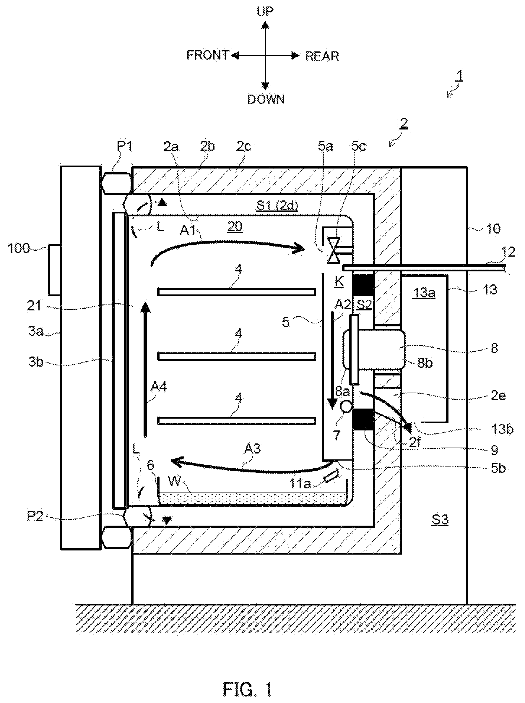
illustrates a schematic longitudinal section of a culture apparatus of an embodiment of the present invention as seen from the right side; and
schematically illustrates the back surface of the culture apparatus of an embodiment of the present invention, with a cover being removed.
DESCRIPTION OF EMBODIMENTS
Hereinafter, a culture apparatus according to an embodiment of the present invention will be described with reference to the accompanying drawings. The following embodiments are merely illustrative, and various modifications and/or applications of techniques which are not specified in the following embodiments are not excluded. In addition, the configurations of the embodiments can be variously modified and implemented without departing from the spirit thereof. Further, the configurations of the embodiments can be selected as necessary, or can be appropriately combined.
In the following description, the side of the culture apparatus which the user faces during usage of the culture apparatus (the side with below-described outer door 3 a and inner door 3 b ) is referred to as “front” and the side opposite to the front is referred to as “rear.” In addition, the left and right are defined with reference to the case of viewing from the front to the rear.
Note that, in all the figures for explaining the embodiments, the same elements are denoted by the same reference numerals in principle, and the description thereof may be omitted.
[1. Configuration]
Culture apparatus 1 in the present embodiment will be described with reference to . illustrates a schematic longitudinal section of the culture apparatus of the present embodiment as seen from the right side. schematically illustrates the back surface of the culture apparatus of the present embodiment, with a cover being removed.
Culture apparatus 1 illustrated in is an apparatus for growing a culture such as a cell or a microorganism. Culture apparatus 1 is configured to include substantially box-shaped heat insulation box 2 having culture space 20 formed inside and opening 21 formed in the front surface, outer door 3 a and inner door 3 b for opening and closing opening 21 . Culture space 20 is vertically compartmentalized by a plurality of (here, three) shelves 4 . Packing P 1 is disposed on the outer edge of outer door 3 a.
As will be described later, in order to achieve an appropriate environment for culturing cells, microorganisms, and the like, culture space 20 is controlled such that the temperature, humidity, and CO 2 concentration are maintained within respective appropriate ranges.
Heat insulation box 2 includes substantially box-shaped inner box 2 a having culture space 20 formed inside, and substantially box-shaped outer box 2 b that covers the outside of inner box 2 a.
Outer box 2 b is provided, on its inner surface side, with heat insulation material 2 c . Space S 1 is formed between the inner surface of heat insulation material 2 c of outer box 2 b and the outer surface of inner box 2 a in such a manner as to cover the upper, lower, left, right, and rear sides of inner box 2 a . This space S 1 is filled with air; the air layer (so-called air jacket) 2 d is formed in space S 1 . Space S 1 corresponds to the first space in the present invention. An opening is located in the front part of space S 1 , and this opening is sealed with packing P 2 . Inner door 3 b and packing P 2 ensure the hermeticity of culture space 20 .
In culture space 20 , vertically extending duct 5 is disposed on the back surface of inner box 2 a . Gas passage K for the air containing CO 2 and the like is formed inside duct 5 . Culture apparatus 1 sucks the air containing CO 2 and the like in culture space 20 through suction port 5 a formed in an upper portion of duct 5 , and blows out the air into culture space 20 through blow-out port 5 b formed in a lower portion of duct 5 . Thus, forced circulation of the air as indicated by arrows A 1 , A 2 , A 3 , and A 4 takes place. Circulation blower 5 c for causing such forced circulation is disposed in duct 5 .
Humidification tray 6 for storing humidification water W is disposed between the lower portion of duct 5 and the bottom plate of inner box 2 a . Humidification tray 6 is heated by a heater wire (not illustrated) disposed on the bottom plate of inner box 2 a , so that water W evaporates.
Inner box 2 a is provided with CO 2 sensor 8 for detecting CO 2 concentration in the air in culture space 20 . The CO 2 sensor is an IR sensor of an infrared light detection system. In the IR sensor, a light-emitting element irradiates the air entering the inside of the sensor with infrared light, this infrared light is received by a light-receiving element, and CO 2 concentration in the air according to the transmittance of infrared light is detected.
Leading end 8 a (one end) of this CO 2 sensor 8 is exposed to culture space 20 , more specifically, to gas passage K in duct 5 , and rear end 8 b (second end) of this CO 2 sensor 8 is attached to heat insulation material 2 c . An opening (not illustrated) for introducing the air between the light-emitting element and the light-receiving element is formed in leading end 8 a of CO 2 sensor 8 .
In space S 1 , that is, in air layer 2 d , sealing material 9 is disposed around the CO 2 sensor. Sealing material 9 is a frame body whose upper side, right side, lower side, and left side are formed integrally. Sealing material 9 is disposed in close contact with the outer surface of inner box 2 a and the inner surface of outer box 2 b (specifically, the inner surface of heat insulation material 2 c ) such that CO 2 sensor 8 is positioned in the frame. That is, frame-shaped sealing material 9 is disposed to surround CO 2 sensor 8 from above, below, left, and right. Thus, sealed space S 2 for providing a seal around CO 2 sensor 8 from above, below, left, and right is formed. Sealing material 9 corresponds to the regulation member in the present invention, and sealed space S 2 corresponds to the second space in the present invention.
In addition, ultraviolet lamp 7 is disposed in duct 5 in order to sterilize the air flowing through duct 5 and thus culture space 20 , and water W in humidification tray 6 below blow-out port 5 b of duct 5 .
Further, culture apparatus 1 receives, from operation device 100 disposed on outer door 3 a , instruction inputs such as an instruction for starting and stopping culture apparatus 1 , a target temperature (e.g., 37° C.), a target humidity (e.g., 93% RH), and/or a target concentration (e.g., 5%) of a CO 2 gas in culture space 20 . A controller (not illustrated) controls the temperature, humidity, and CO 2 concentration in culture space 20 such that the temperature, humidity, and CO 2 concentration are at the above-mentioned target values.
The back and bottom surfaces of outer box 2 b of heat insulation box 2 are covered with cover 10 . The space between the back surface of outer box 2 b and cover 10 forms mechanical room S 3 for disposing various equipment therein. Gas supply device 12 for supplying a CO 2 gas to culture space 20 , sensor box 13 , a temperature sensor (not illustrated) for measuring the temperature in culture space 20 , and an electrical box (not illustrated) for accommodating electrical components such as the control device are disposed in mechanical room S 3 .
Rear end 8 b of CO 2 sensor 8 is exposed in mechanical room S 3 . Sensor box 13 is a box that opens forward, and covers rear end 8 b of CO 2 sensor 8 from the rear in mechanical room S 3 . A temperature adjustment device is disposed in sensor box 13 . By keeping the temperature of inner space 13 a of sensor box 13 within a predetermined range by this temperature adjustment device, the sensitivity of the detection accuracy of CO 2 sensor 8 is kept constant.
In addition, opening 13 b is formed in the bottom wall of sensor box 13 and opening 13 c is formed in the lower portion of the right side wall and the lower portion of the left side wall of sensor box 13 .
Passage 2 e is formed in heat insulation material 2 c below CO 2 sensor 8 . This passage 2 e communicates with sealed space S 2 and mechanical room S 3 , and, in the present embodiment, also communicates with the inner space of sensor box 13 . Bottom surface 2 f of passage 2 e is an inclined surface inclined downward from sealed space S 2 toward mechanical room S 3 .
Further, as illustrated in , dew condensation member 11 a is disposed on the back surface of heat insulation box 2 . This dew condensation member 11 a is inserted into culture space 20 from mechanical room S 3 . It is preferable that dew condensation member 11 a have higher conductivity, and the dew condensation member is, for example, a round bar with a predetermined length that is made of aluminum, silver or the like. Peltier element 11 b is disposed on an end of dew condensation member 11 a within mechanical room S 3 such that the heat-absorbing surface of the Peltier element 11 b faces the end. The dew condensation member is cooled by the heat-absorbing surface. Accordingly, dew condensation water is generated on the surface of dew condensation member 11 a in culture space 20 , and consequently, the humidity in culture space 20 can be controlled within a predetermined range. Note that, the dew condensation water generated on the surface of dew condensation member 11 a drips from dew condensation member 11 a into humidification tray 6 .
Further, comb-shaped heat sink 11 c disposed on the heating surface of Peltier element 11 b , blowing device 11 d for supplying cooling air toward this heat sink 11 c , and guide member 11 e are disposed in mechanical room S 3 . In the present embodiment, dew condensation member 11 a , Peltier element 11 b , heat sink 11 c , and blowing device 11 d are disposed on the left side of sensor box 13 . The cooling air that is blown from blowing device 11 d and heated after cooling Peltier element 11 b via heat sink 11 c is guided by guide member 11 e to opening 13 c positioned in the left side surface of sensor box 13 .
[2. Effects]
(1) As described above, in the conventional culture apparatus, the CO 2 sensor is disposed in the sensor box, and the air in the culture space is supplied into the sensor box through the pipe. On the other hand, in culture apparatus 1 illustrated in , leading end 8 a of CO 2 sensor 8 is exposed to culture space 20 (specifically, in duct 5 ). Thus, in this culture apparatus 1 , the pipe for supplying air in the culture space into the sensor box is not necessary. Therefore, according to culture apparatus 1 of one embodiment of the present invention, it is possible to achieve a simpler configuration and a greater cost reduction than the conventional culture apparatus because of the unnecessity of the pipe, and it is also possible to reduce the size by omitting the space occupied by the pipe.
(2) Although space S 1 (air layer 2 d ) in which CO 2 sensor 8 is inserted is sealed by packing P 2 , leakage flow L may occur as indicated by the arrows of dashed dotted lines in . That is, air in culture space 20 may flow into air layer 2 d . When the air in culture space 20 flows into air layer 2 d and the air stays between the light-emitting element and the light-receiving element in CO 2 sensor 8 , this staying air becomes a factor of error for sequential measurement of CO 2 concentration in the air in culture space 20 . Consequently, the CO 2 concentration in culture space 20 cannot be accurately controlled based on the detection result of CO 2 sensor 8 . However, leakage flow L toward CO 2 sensor 8 is regulated by disposing sealing material 9 in space S 1 , and it is thus possible to reduce the measurement error in CO 2 concentration caused by leakage flow L, and consequently, it is possible to control the CO 2 concentration in culture space 20 with high accuracy.
(3) In space S 1 , sealed space S 2 is provided around CO 2 sensor 8 by surrounding CO 2 sensor 8 with sealing material 9 (from above, below, left, and right). The presence of sealed space S 2 makes it possible to effectively reduce leakage flow L reaching CO 2 sensor 8 to reduce the measurement error in CO 2 concentration more effectively.
(4) Passage 2 e that communicates from sealed space S 2 to the outside of outer box 2 b (in this case, mechanical room S 3 ) is formed in heat insulation material 2 c of outer box 2 b . It is thus possible to discharge leakage flow L from sealed space S 2 even if leakage flow L passes sealing material 9 to flow into sealed space S 2 , so as to reduce measurement error in CO 2 concentration more effectively.
In particular, in the present embodiment, passage 2 e is formed on the lower side in sealed space S 2 , and further, bottom surface 2 f of passage 2 e is inclined downward from sealed space S 2 toward mechanical room S 3 outside sealed space S 2 , and it is thus possible to reduce the measurement error in CO 2 concentration more effectively for the following reason: CO 2 has a greater specific gravity among the components contained in the air, and thus tends to accumulate in sealed space S 2 when leakage flow L flows into sealed space S 2 ; however, the CO 2 gas sequentially accumulated in sealed space S 2 can be smoothly discharged to mechanical room S 3 as a result of formation of passage 2 e on the lower side in sealed space S 2 and bottom surface 2 f of passage 2 e inclined downward to mechanical room S 3 .
(5) The effects of culture apparatus 1 will further be described with reference to . The arrows of thick solid lines indicate the flow of air (cooling air) sent under pressure by blowing device 11 d . The arrows of thick dashed lines indicate the flow of gases (hereinafter referred to as “CO 2 gas”) mainly containing CO 2 discharged into mechanical room S 3 and sensor box 13 from sealed space S 2 .
Air (cooling air) sent under pressure by blowing device 11 d cools the heating surface of Peltier element 11 b cooling dew condensation member 11 a , is heated, and then flows into sensor box 13 through opening 13 c on the left side by the guide of guide member 11 e . A part of this inflow air flows out of sensor box 13 through opening 13 b formed in the bottom surface of sensor box 13 . At that time, the part of the inflow air expels the CO 2 gas in sensor box 13 through opening 13 b and flows out through opening 13 b while entraining the CO 2 gas in sensor box 13 . Another part of the air flowed into sensor box 13 expels the CO 2 gas in sensor box 13 through opening 13 c on the right side and flows out through opening 13 c while entraining the CO 2 gas in sensor box 13 . Therefore, since the CO 2 gas in sealed space S 2 and/or sensor box 13 is sequentially discharged, the CO 2 gas does not stay in sealed space S 2 , and it is possible to reduce the influence on measurement of CO 2 concentration by CO 2 sensor 8 .
Further, the temperature of CO 2 sensor 8 can be maintained at an appropriate temperature by the temperature in sensor box 13 raised by the air (cooling air) having cooled the heating surface of Peltier element 11 b and thus heated.
[3. Others]
Although CO 2 sensor 8 is surrounded from above, below, left, and right by sealing material 9 , which is the regulation member, in space S 1 (air layer 2 d ) in the above embodiment, one, two, or three regulation members may be disposed on one, two, or three of the upper, lower, left, and right sides of CO 2 sensor 8 . Alternatively, another frame-shaped sealing material may also be disposed on the outer peripheral side of sealing material 9 . That is, a plurality of sealing materials 9 surrounding CO 2 sensor 8 in a multilayered manner may be disposed. In short, the shape, arrangement, and number of the regulation members are not limited as long as the regulation member(s) regulate the airflow toward CO 2 sensor 8 .
The disclosure of Japanese Patent Application No. 2018-166645, filed on Sep. 6, 2018, including the specification, claims, drawings and abstract is incorporated herein by reference in its entirety.
INDUSTRIAL APPLICABILITY
The present invention can provide a culture apparatus achieving cost reduction and size reduction. Therefore, the industrial applicability of the present invention is enormous.
REFERENCE SIGNS LIST
•
• 1 Culture apparatus • 2 Heat insulation box • 2 a Inner box • 2 b Outer box • 2 c Heat insulation material • 2 d Air layer • 2 e Passage • 2 f Bottom surface • 3 a Outer door • 3 b Inner door • 4 Shelf • 5 Duct • 5 a Suction port • 5 b Blow-out port • 5 c Circulation blower • 6 Humidification tray • 7 Ultraviolet lamp • 8 Co 2 sensor • 8 a Leading end (first end) • 8 b Rear end (second end) • 9 sealing material (regulation member) • 10 Cover • 11 a Dew condensation member • 11 b Peltier element • 11 c Heat sink • 11 d Blowing device • 11 e Guide member • 12 Gas supply device • 13 Sensor box • 13 a Inner space • 13 b Opening • 13 c Opening • 20 Culture space • 21 Opening • 100 Operation device • K Gas passage • L Leakage flow • P 1 , P 2 Packing • S 1 Space (first space) • S 2 Sealed space (second space) • S 3 Mechanical room • W Water
Figures (2)
Citations
This patent cites (14)
- US5090617
- US5418131
- US5773287
- US6297047
- US10918755
- US2002/0047311
- US2005/0084956
- US2006/0148094
- US2010/0173401
- US2016/0010048
- US69534425
- USH03-065176
- US2010-154793
- US2017-035013