Image Forming System, Post-processing Apparatus and Binding Device
Abstract
An image forming system including an image forming apparatus configured to form an image on a sheet, a post-processing apparatus comprising a binding device configured to bind the sheet output from the image forming apparatus, and a control unit configured to control the binding device. The binding device is capable of executing binding processing via a staple forming process of forming a staple and moving the staple toward a striking-out position and a staple striking-out process of striking out the staple at the striking-out position. The control unit is configured to control the binding device to repeat multiple times the staple forming process without undergoing the staple striking-out process.
Claims (13)
1. An image forming system comprising: an image forming apparatus configured to form an image on a sheet; a post-processing apparatus comprising a binding device configured to bind the sheet output from the image forming apparatus; and a control unit configured to control the binding device, wherein the binding device is capable of executing binding processing via a staple forming process of forming a staple and moving the staple toward a striking-out position and a staple striking-out process of striking out the staple at the striking-out position, and wherein the control unit is configured to control the binding device to repeat multiple times the staple forming process without undergoing the staple striking-out process.
5. A post-processing apparatus comprising: a binding device configured to bind a sheet output from an image forming apparatus configured to form an image on the sheet; and a control unit configured to control the binding device, wherein the binding device is capable of executing binding processing via a staple forming process of forming a staple and moving the staple toward a striking-out position and a staple striking-out process of striking out the staple at the striking-out position, and wherein the control unit is configured to control the binding device to repeat multiple times the staple forming process without undergoing the staple striking-out process.
8. A binding device comprising: a staple forming unit configured to form a staple and to move the staple toward a striking-out position; a staple striking-out unit configured to strike out the staple at the striking-out position; and a cam configured to actuate the staple forming unit and the staple striking-out unit, wherein the cam has a first cam surface for actuating the staple forming unit and the staple striking-out unit, and a second cam surface for actuating the staple forming unit by bypassing all or part of actuation of the staple striking-out unit by the first cam surface.
Show 10 dependent claims
2. The image forming system according to claim 1 , wherein the control unit is configured to control the binding device so as to be able to switch: a first mode in which the binding processing is executed via the staple forming process and the staple striking-out process, and a second mode in which staple initial setting processing of repeating multiple times the staple forming process without undergoing the staple striking-out process is executed.
3. The image forming system according to claim 2 , wherein the binding device comprises: a staple forming unit configured to form a staple and moving the staple toward the striking-out position in the staple forming process, a staple striking-out unit configured to strike out the staple at the striking-out position in the staple striking-out process, and a displaceable actuation unit, the staple forming unit or the staple striking-out unit being configured to be actuated according to a displacement direction and a displacement amount of the actuation unit, and wherein the control unit is configured to control the displacement direction and displacement amount of the actuation unit to switch a number of actuations of the staple forming unit and presence or absence of actuation of the staple striking-out unit.
4. The image forming system according to claim 3 , wherein the binding device comprises a plurality of the staple forming units, a plurality of the staple striking-out units, a plurality of the actuation units, and a single motor configured to drive the plurality of actuation units, and wherein the control unit is configured to control the actuation unit via the motor.
6. The post-processing apparatus according to claim 5 , wherein the binding device comprises: a staple forming unit configured to form a staple and moving the staple toward the striking-out position in the staple forming process, a staple striking-out unit configured to strike out the staple at the striking-out position in the staple striking-out process, and a displaceable actuation unit, wherein the staple forming unit or the staple striking-out unit is configured to be actuated according to a displacement direction and a displacement amount of the actuation unit, and wherein the control unit is configured to control the displacement direction and displacement amount of the actuation unit to switch a number of actuations of the staple forming unit and presence or absence of actuation of the staple striking-out unit.
7. The post-processing apparatus according to claim 6 , wherein the binding device comprises a plurality of the staple forming units, a plurality of the staple striking-out units, a plurality of the actuation units, and a single motor configured to drive the plurality of actuation units, and wherein the control unit is configured to control the actuation unit via the motor.
9. The binding device according to claim 8 , wherein the first cam surface has a staple forming cam surface for actuating the staple forming unit, and a staple striking-out cam surface for actuating the staple striking-out unit, and wherein the second cam surface has a staple forming cam surface for actuating the staple forming unit, and a staple striking-out regulation cam surface for bypassing part or all of the staple striking-out cam surface.
10. The binding device according to claim 9 , wherein the cam is a rotation-type cam configured to rotate with a shaft as a fulcrum and having the first and second cam surfaces formed in a circumferential direction, wherein the staple forming cam surface is formed on one surface in an axial direction of the cam, and wherein the staple striking-out cam surface and the staple striking-out regulation cam surface are formed on the other surface in the axial direction.
11. The binding device according to claim 10 , wherein the staple forming cam surface is formed in a region that partially or fully overlaps the staple striking-out cam surface and the staple striking-out regulation cam surface along a rotation direction of the cam.
12. The binding device according to claim 11 , wherein the staple striking-out unit comprises a driver follower in contact with the staple striking-out regulation cam surface, and wherein the second cam surface comprises a regulation portion configured to regulate movement of the driver follower from the staple striking-out regulation cam surface toward the staple striking-out cam surface.
13. The binding device according to claim 8 , further comprising: a plurality of the staple forming units each configured to form a staple and to move the staple toward a striking-out position; a plurality of the staple striking-out units each configured to strike out the staple at the striking-out position; a plurality of the cams configured to actuate the plurality of staple forming units and the plurality of staple striking-out units, and a single motor configured to drive the cams.
Full Description
Show full text →
CROSS-REFERENCE TO RELATED APPLICATIONS
The present application claims priority from Japanese Patent Application No. 2022-124540 filed on Aug. 4, 2022, the entire content of which is incorporated herein by reference.
TECHNICAL FIELD
The present disclosure relates to an image forming system including an image forming apparatus that forms an image on a sheet, and a post-processing apparatus having a binding device that binds a sheet output from the image forming apparatus, a post-processing apparatus and a binding device.
BACKGROUND ART
An electric stapler attached to an image forming apparatus, a post-processing apparatus or the like includes a forming plate for forming a straight staple needle into a U-shape, a driver plate for striking out the U-shaped staple needle into a sheet, and a feeding unit for delivering the staple needle toward a position below the forming plate and the driver plate. The staple needles are connected in a sheet shape and accommodated in the electric stapler as sheet-like staples.
The forming plate is located upstream of the driver plate in a feeding direction of the sheet-like staples, and the forming plate and the driver plate are configured to be actuated in conjunction with each other. Therefore, when the forming plate and the driver plate are operated in a state where the staple needles are located at positions below the forming plate and the driver plate, respectively, the staple needles at the position below the forming plate are each formed in a U-shape, and the staple needles at the position below the driver plate are each struck out.
In the meantime, there is a case where when the electric stapler is activated, a leading staple of the sheet-shaped staples is not located below the forming plate or the driver plate. For this reason, it is necessary to perform a staple initial setting of moving (feeding) a leading staple to a position below the driver plate by repeating an operation until the leading staple is located below the driver plate, i.e., until the leading staple is in a state where it can be actually struck out.
However, a so-called idle striking is performed by the driver plate while the staple initial setting is performed, i.e., until the staple is located below the driver plate, and resultantly, a problem occurs in which an idle striking mark is left on a sheet.
For example, disclosed is an automatic binding preparation mechanism for an electric stapler where a detection means detects whether a leading staple is located below a driver plate, and a sheet to be bound is kept on standby without being set until it is detected by the detection means that the leading staple is located below the driver plate, i.e., until actual striking-out is possible (Japanese Patent No. 2932438). According to this mechanism, since the sheet to be bound is not set until the staple initial setting is completed, no idle striking mark is left on the sheet to be bound.
SUMMARY OF INVENTION
However, in the mechanism described in Japanese Patent No. 2932438, the sheet should stand by without being set until actual striking-out is possible, and when it is intended to perform staple initial setting in a state where the sheet is set, an idle striking mark is left on the sheet.
Therefore, an object of the present disclosure is to provide an image forming system and a post-processing apparatus including a binding device configured such that no idle striking mark is left on a sheet even when a staple initial setting is performed in a state where the sheet is set, and a binding device.
An image forming system according to the present disclosure includes an image forming apparatus configured to form an image on a sheet, a post-processing apparatus including a binding device configured to bind the sheet output from the image forming apparatus, and a control unit configured to control the binding device. The binding device is capable of executing binding processing via a staple forming process of forming a staple and moving the staple toward a striking-out position and a staple striking-out process of striking out the staple at the striking-out position, and the control unit is configured to control the binding device to repeat multiple times the staple forming process without undergoing the staple striking-out process.
Since the binding device is controlled by the control unit to repeat multiple times the staple forming process without undergoing the staple striking-out process, during this control, the staple is moved (fed) toward the striking-out position, but a staple striking-out operation is not performed. For this reason, even when the staple initial setting is performed in a state where the sheet is set in the device in advance, an idle striking mark due to the striking-out operation is not left on the sheet.
In addition, a post-processing apparatus according to the present disclosure includes a binding device configured to bind a sheet output from an image forming apparatus configured to form an image on the sheet, and a control unit configured to control the binding device. The binding device is capable of executing binding processing via a staple forming process of forming a staple and moving the staple toward a striking-out position and a staple striking-out process of striking out the staple at the striking-out position, and the control unit is configured to control the binding device to repeat multiple times the staple forming process without undergoing the staple striking-out process.
Since the binding device attached to the image forming system or post-processing apparatus described above is controlled by the control unit to repeat multiple times the staple forming process without undergoing the staple striking-out process, during this control, the staple is moved (fed) toward the striking-out position, but the staple striking-out operation is not performed. For this reason, even when the sheet has already been set, an idle striking mark due to the striking-out operation is not left on the sheet.
A binding device according to the present disclosure includes a staple forming unit configured to form a staple and to move the staple toward a striking-out position, a staple striking-out unit configured to strike out the staple at the striking-out position, and a cam configured to actuate the staple forming unit and the staple striking-out unit. The cam has a first cam surface for actuating the staple forming unit and the staple striking-out unit, and a second cam surface for actuating the staple forming unit by bypassing all or part of actuation of the staple striking-out unit by the first cam surface.
When actuating the staple forming unit or the staple striking-out unit by the cam, the binding device uses the first cam surface and thus can execute a binding operation by forming of a staple and striking-out of the formed staple, while the binding device uses the second cam surface and thus can execute the staple initial setting of actuating the staple forming unit by bypassing all or part of the staple striking-out operation. When executing the staple initial setting operation by using the second cam surface, the staple forming unit is actuated by bypassing all or part of the staple striking-out operation, and accordingly, the staple can be fed without leaving an idle striking mark due to the striking-out operation on the sheet.
A binding device according to the present disclosure includes a plurality of staple forming units each configured to form a staple and to move the staple toward a striking-out position, a plurality of staple striking-out units each configured to strike out the staple at the striking-out position, a plurality of cams configured to actuate the plurality of staple forming units and the plurality of staple striking-out units, and a single motor configured to drive the cams, in which each of the cams has a first cam surface for actuating the staple forming unit and the staple striking-out unit, and a second cam surface for actuating the staple forming unit by bypassing all or part of actuation of the staple striking-out unit by the first cam surface.
In order to bind a plurality of places of sheet at once, a binding device that actuates a plurality of staple forming units and staple striking-out units with one motor is sometimes used. In such a binding device, there is a case in which positions of staples of the plurality of staple forming units are not matched, such as after replacement of the staples. For example, the staple of one staple forming unit is located at the forming position or striking-out position, while the staple of another staple forming unit is not located at the forming position or striking-out position. In such a case, in the present binding device, since the staple feeding is repeated multiple times (e.g., 2 to 3 times) without striking out the staple after the staple forming operation, the positions of the staples of the plurality of staple forming units can be matched (the staple initial setting processing can be completed) without leaving an idle striking mark on the sheet.
Even when the sheet is set in the binding device in advance, the staple initial setting can be performed without leaving an idle striking mark on the sheet.
BRIEF DESCRIPTION OF DRAWINGS
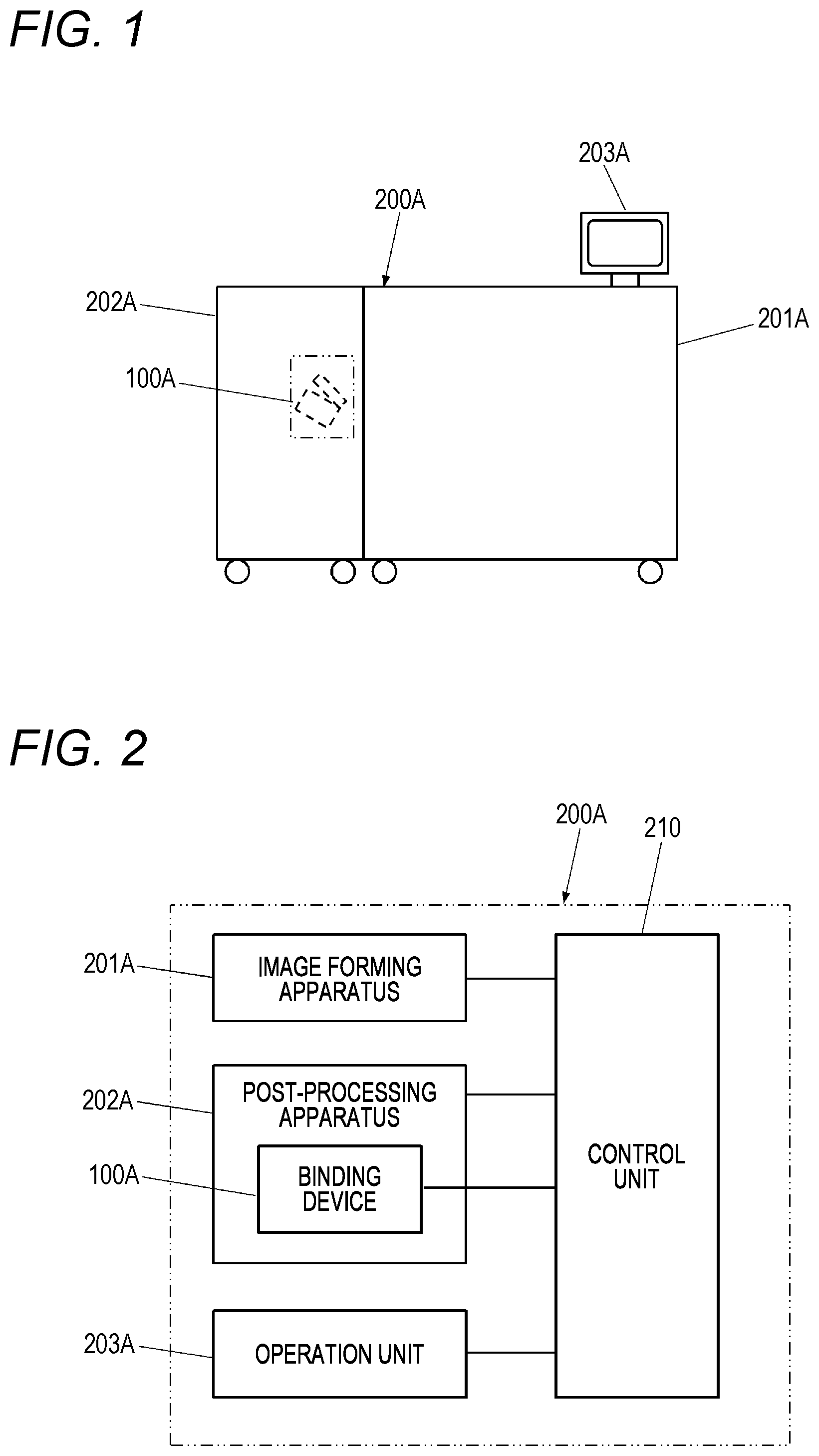
is a configuration diagram showing an example of an embodiment of an image forming system and a post-processing apparatus.
is a block diagram showing an example of the embodiment of the image forming system and the post-processing apparatus.
illustrates an example of a staple.
A illustrates an example of an operation of the image forming system and post-processing apparatus.
B illustrates the example of the operation of the image forming system and post-processing apparatus.
C illustrates the example of the operation of the image forming system and post-processing apparatus.
D illustrates the example of the operation of the image forming system and post-processing apparatus.
E illustrates the example of the operation of the image forming system and post-processing apparatus.
F illustrates the example of the operation of the image forming system and post-processing apparatus.
G illustrates the example of the operation of the image forming system and post-processing apparatus.
A illustrates an example of an operation of the image forming system and post-processing apparatus.
B illustrates the example of the operation of the image forming system and post-processing apparatus.
C illustrates the example of the operation of the image forming system and post-processing apparatus.
is a flowchart showing an example of an operation of a control unit.
A illustrates an example of an operation of the image forming system and post-processing apparatus having a binding device of another embodiment.
B illustrates the example of the operation of the image forming system and post-processing apparatus having the binding device of another embodiment.
C illustrates the example of the operation of the image forming system and post-processing apparatus having the binding device of another embodiment.
D illustrates the example of the operation of the image forming system and post-processing apparatus having the binding device of another embodiment.
E illustrates the example of the operation of the image forming system and post-processing apparatus having the binding device of another embodiment.
F illustrates the example of the operation of the image forming system and post-processing apparatus having the binding device of another embodiment.
is a perspective view showing an example of an embodiment of a binding device.
A is a side cross-sectional view showing an example of an embodiment of a forming striking-out unit and a bending unit.
B is a side cross-sectional view showing the example of the embodiment of the forming striking-out unit and the bending unit.
is a side view showing the example of the embodiment of the forming striking-out unit and the bending unit.
A is a front cross-sectional view showing the example of the embodiment of the forming striking-out unit and the bending unit.
B is a front cross-sectional view showing the example of the embodiment of the forming striking-out unit and the bending unit.
is a front view showing the example of the embodiment of the forming striking-out unit and the bending unit.
A illustrates an example of a function assigned to a driver cam in a striking-out mode.
B illustrates an example of a function assigned to a forming cam in the striking-out mode.
C illustrates an example of a function assigned to the driver cam in an initial setting mode.
D illustrates an example of a function assigned to the forming cam in the initial setting mode.
A is an operation illustrating view showing an example of a flow of the striking-out mode.
B is an operation illustrating view showing an example of a flow of the initial setting mode.
A is a side cross-sectional view showing an example of an operation of the driver cam in the striking-out mode.
B is a side cross-sectional view showing an example of an operation of the forming cam in the striking-out mode.
A is a front cross-sectional view showing an example of an operation of a driver plate in the striking-out mode.
B is a front cross-sectional view showing an example of an operation of a forming plate in the striking-out mode.
A is a side cross-sectional view showing an example of an operation of the driver cam in the initial setting mode.
B is a side cross-sectional view showing an example of an operation of the forming cam in the initial setting mode.
A is a front cross-sectional view showing an example of an operation of the driver plate in the initial setting mode.
B is a front cross-sectional view showing an example of an operation of the forming plate in the initial setting mode.
is a perspective view showing an example of another embodiment of the binding device.
A is an operation illustrating view showing an example of the initial setting operation in the binding device having two forming striking-out units.
B is an operation illustrating view showing an example of the initial setting operation in the binding device having two forming striking-out units.
A is a schematic view showing another example of an embodiment of an actuating unit.
B is an operation illustrating view showing an example of a flow of the striking-out mode and the initial setting mode.
A is a schematic view showing another example of the embodiment of the actuating unit.
B is an operation illustrating view showing an example of the flow of the striking-out mode and the initial setting mode.
is a block diagram showing an example of an embodiment of the image forming system and post-processing apparatus having a binding device according to still another embodiment.
A illustrates an example of an operation of the image forming system and post-processing apparatus having the binding device according to still another embodiment.
B illustrates the example of the operation of the image forming system and post-processing apparatus having the binding device according to still another embodiment.
C illustrates the example of the operation of the image forming system and post-processing apparatus having the binding device according to still another embodiment.
D illustrates the example of the operation of the image forming system and post-processing apparatus having the binding device according to still another embodiment.
E illustrates the example of the operation of the image forming system and post-processing apparatus having the binding device according to still another embodiment.
is a flowchart showing an example of an operation of the image forming system and post-processing apparatus having the binding device according to still another embodiment.
DESCRIPTION OF EMBODIMENTS
Hereinafter, embodiments of an image forming system, a post-processing apparatus, and a binding device of the present invention will be described with reference to the drawings.
<Example of Embodiment of Image Forming System and Post-Processing Apparatus>
is a configuration diagram showing an example of an embodiment of an image forming system and a post-processing apparatus, is a block diagram showing an example of the embodiment of the image forming system and the post-processing apparatus, and illustrates an example of a staple.
In addition, A to 4 G illustrate an example of an operation of the image forming system and post-processing apparatus, showing a second mode (initial setting mode) in which staple initial setting processing of repeating multiple times a staple forming process without undergoing a staple striking-out process is executed. Further, A to 5 C illustrate an example of an operation of the image forming system and post-processing apparatus, showing a first mode (striking-out mode) in which binding processing is executed via the staple forming process and the staple striking-out process.
An image forming system 200 A includes an image forming apparatus 201 A that forms an image on a sheet, a post-processing apparatus 202 A having a binding device 100 A that binds the sheet output from the image forming apparatus 201 A with a staple 10 , and an operation unit 203 A that receives a person's operation. In addition, the image forming system 200 A includes a control unit 210 that controls the binding device 100 A. Note that the control unit 210 may be provided in any of the image forming apparatus 201 A, the post-processing apparatus 202 A, and the binding device 100 A. However, in the present example, an example in which the control unit is provided in the post-processing apparatus 202 A will be described. The control unit 210 may include a processor such as a central processing unit (CPU), a micro processing unit (MPU), or the like.
As shown in , the staple 10 has a straight shape before forming. A plurality of staples 10 are aligned in a width direction and are detachably connected by an adhesive or the like to form a sheet shape (the plurality of staples 10 in the form of a sheet are hereinafter referred to as “sheet staples 11 ”), and the sheet staples 11 are stacked and accommodated in the binding device 100 A. The lowermost sheet staple 11 of the stacked sheet staples 11 is fed in a direction of an arrow E 1 , which is a connecting direction of the staples 10 , and is formed into a U-shape.
As shown in A to 4 F , the binding device 100 A can execute binding processing via a staple forming process of forming a staple 10 and moving the staple toward a striking-out position P 2 and a staple striking-out process of striking out the staple 10 at the striking-out position P 2 , and includes a staple forming unit 2 A that forms the staple 10 and moves the staple toward the striking-out position P 2 in the staple forming process, and a staple striking-out unit 2 B that strikes out the staple 10 at the striking-out position P 2 in the staple striking-out process. The staple forming unit 2 A includes a forming plate 20 that forms the staple 10 at a forming position P 1 , a staple feeding unit 50 that moves the formed staple 10 toward the striking-out position P 2 , and moves a next unformed staple 10 (sheet staple 11 ) toward the forming position P 1 . In addition, the staple striking-out unit 2 B includes a driver plate 21 that strikes out the staple 10 at the striking-out position P 2 .
The staple feeding unit 50 includes a claw portion 51 that is engaged with the staple and a link portion 52 that is pushed by the forming plate 20 in an operation in which the forming plate 20 is moved in a direction of an arrow F 10 , and is urged in a direction of an arrow E 1 , which is a feeding direction of the staple 10 , by a spring 53 .
In an operation in which the forming plate 20 is moved in the direction of the arrow F 10 for forming the staple 10 , the link portion 52 is pushed by the forming plate 20 , so that the staple feeding unit 50 is moved in a direction of an arrow E 2 while compressing the spring 53 . In an operation in which the forming plate 20 is moved in a direction of an arrow F 20 away from the staple 10 , the link portion 52 is released from being pushed by the forming plate 20 , so that the staple feeding unit 50 is moved in the direction of the arrow E 1 by the force of the spring 53 .
Thereby, in the operations in which the forming plate 20 are moved in the directions of the arrows F 10 and F 20 , the staple feeding unit 50 reciprocates in the directions of the arrows E 1 and the arrow E 2 , and feeds the staple 10 engaged with the claw portion 51 in the direction of the arrow E 1 .
Note that the staple feeding unit 50 is not limited to operating in conjunction with the forming plate 20 , and may be configured to operate in conjunction with the driver plate 21 , or may have a drive source independent of the forming plate 20 and the driver plate 21 .
Before the staple initial setting processing is completed, the forming plate 20 and the driver plate 21 are each located at a standby position ( A ). From this state, when the forming plate 20 is moved in the direction of the arrow F 10 , the staple 10 at the forming position P 1 is formed and the link portion 52 is pushed by the forming plate 20 , so that the staple feeding unit 50 is moved in the direction of the arrow E 2 while compressing the spring 53 ( B ).
After moving the forming plate 20 in the direction of the arrow F 10 , when the forming plate 20 is moved in the direction of the arrow F 20 , the link portion 52 is released from being pushed by the forming plate 20 , so that the staple feeding unit 50 is moved in the direction of the arrow E 1 by the force of the spring 53 . Thereby, the staple 10 is fed in the direction of the arrow E 1 toward the striking-out position P 2 ( C ).
Below, control of repeating the staple forming process multiple times without undergoing the staple striking-out process will be described.
shows an example of an operation of the control unit 210 . In the standby state ( A ) in which the staple initial setting processing has not been completed and the forming plate 20 and the driver plate 21 have been moved to their respective standby positions, the control unit 210 causes the binding apparatus 100 A to execute the staple forming process, in step SA 10 of ( B ). At this time, by regulating actuation of the driver plate 21 or regulating an amount of actuation thereof, the staple striking-out process is not undergone (not executed), so the driver plate 21 is not actuated and only the forming plate 20 is moved in the direction of the arrow F 10 , as shown in B . Thereby, the staple 10 at the forming position P 1 is formed. When the amount of actuation of the driver plate 21 is regulated, the driver plate 21 is moved in the direction of the arrow F 10 within a range in which it does not come into contact with the staple 10 .
In addition, as the link portion 52 is pushed by the forming plate 20 in the operation in which the forming plate 20 is moved in the direction of the arrow F 10 for forming the staple the staple feeding unit 50 is moved in the direction of the arrow E 2 while compressing the spring 53 .
After moving the forming plate 20 in the direction of the arrow F 10 , the control unit 210 moves the forming plate 20 in the direction of the arrow F 20 , as shown in C . As the forming plate 20 is moved in the direction of the arrow F 20 away from the formed staple 10 , the link portion 52 is released from being pushed by the forming plate 20 and is moved in the direction of the arrow E 1 by the force of the spring 53 . Thereby, the staple 10 is fed in the direction of the arrow E 1 toward the striking-out position P 2 . The first staple forming process is executed by the above operations in B and 4 C .
The control unit 210 determines in step SA 20 of whether the staple initial setting processing has ended. If it is determined that the staple initial setting processing has not ended, the control unit returns to step SA 10 and again causes the binding device 100 A to execute the staple forming process without undergoing the staple striking-out process. That is, the control unit 210 sets a predetermined state of regulating the actuation of the driver plate 21 or regulating the amount of actuation, and moves the forming plate 20 in the direction of the arrow F 10 as shown in D . Thereby, the next staple 10 moved to the staple forming position P 1 in the previous staple forming process is formed.
After moving the forming plate 20 in the direction of the arrow F 10 , the control unit 210 moves the forming plate 20 in the direction of the arrow F 20 , as shown in E . Thereby, the staple 10 is fed in the direction of the arrow E 1 toward the striking-out position P 2 . The second staple forming process is executed by the above operations in D and 4 E .
In the present example, since the formed staple 10 is moved to the striking-out position P 2 by the second staple forming process, the staple 10 formed in the staple forming process is reliably moved to the striking-out position P 2 by performing the staple forming process two times or more.
After the second staple forming process is executed, the control unit 210 proceeds to step SA 20 , but determines that the staple initial setting processing has not yet ended, and executes the staple forming process again in step SA 10 . The control unit 210 moves the forming plate 20 in the direction of the arrow F 10 , as shown in F , in order to execute the third and subsequent staple forming processes without undergoing the staple striking-out process. Thereby, the next staple 10 moved to the staple forming position P 1 in the previous staple forming process is formed.
After moving the forming plate 20 in the direction of the arrow F 10 , the control unit 210 moves the forming plate 20 in the direction of the arrow F 20 , as shown in G . In the third and subsequent staple forming processes, the staple 10 formed in the staple forming process has been already moved to the striking-out position P 2 . In the present example, since a staple stopper (not shown) for limiting feeding of the staple is provided at an end of the striking-out position P 2 , a so-called idle feeding is made in which even when the staple feeding unit 50 is moved in the direction of the arrow E 1 , the staple 10 is not fed. The second and subsequent staple forming processes are executed by the above operations in F and 4 G . In addition, the binding device 100 A does not have a means for detecting the staple at the striking-out position P 2 .
In the present example, after the staple forming process has been executed three times, the control unit 210 determines in step SA 20 of that the staple initial setting processing has ended, and ends the processing. As described above, the control unit 210 controls the binding device 100 A to repeat the staple forming process multiple times without undergoing the staple striking-out process. Note that in the staple forming process that is executed without undergoing the staple striking-out process, the driver plate 21 may be moved within a range in which it does not come into contact with the staple 10 . According to the image forming system 200 A, the staple forming process can be repeated multiple times without involving the striking-out of the staple 10 , i.e., without performing so-called idle striking. In addition, even after the leading staple 10 is moved to the striking-out position P 2 , the staple forming process can be executed without involving the striking out of the leading staple 10 . Therefore, there is no need to set the sheet in order to prevent the leading staple 10 from being struck out without a sheet, and the staple initial setting processing can be executed by executing the staple forming process in a state where a sheet is not set. Further, even when a sheet is set, an idle striking mark due to idle striking is not left on the sheet. Therefore, regardless of the presence or absence of a sheet, it is possible to execute the staple initial setting processing by executing the staple forming process. Further, it is possible to perform the initial setting for the staple 10 without the need for the binding device 100 A to have a means for detecting that the staple 10 is present at the striking-out position P 2 . Further, as compared with a case where the idle striking is performed (the driver plate 21 is moved to the striking-out position), it is possible to shorten an operating time required for the staple initial setting.
The control unit 210 controls the binding device 100 A to be able to switch a first mode (striking-out mode) in which the binding processing is performed via the staple forming process and the staple striking-out process, and a second mode (initial setting mode) in which the staple initial setting processing is executed by repeating multiple times the staple forming process without undergoing the staple striking-out process.
First, the first mode will be described.
A shows a standby state in which the forming plate 20 and the driver plate 21 are respectively located at standby positions. In the control of executing the binding processing via the staple forming process and the staple striking-out process, i.e., in the first mode, the forming plate 20 and the driver plate 21 are actuated in conjunction with each other. For this reason, part or all of the staple striking-out process and the staple forming process are executed overlapped on a time-series basis.
In the first mode, the control unit 210 moves the forming plate 20 in the direction of the arrow F 10 and moves the driver plate 21 in the direction of the arrow F 1 , as shown in B . Thereby, the staple 10 at the forming position P 1 is formed by the forming plate 20 , and the staple 10 at the striking-out position P 2 is struck out by the driver plate 21 .
After moving the forming plate 20 in the direction of the arrow F 10 and moving the driver plate 21 in the direction of the arrow F 1 , as shown in C , when the forming plate 20 is moved in the direction of the arrow F 20 and the driver plate 21 is moved in the direction of the arrow F 2 , the link portion 52 is released from being pushed by the forming plate 20 , and is moved in the direction of the arrow E 1 by the force of the spring 53 . Thereby, the staple 10 is fed in the direction of the arrow E 1 .
Next, the second mode will be described. In the second mode, the operations of A to 4 G and the control of described above are performed, and the binding device 100 A is controlled to repeat the staple forming process multiple times without undergoing the staple striking-out process by the control unit 210 .
A to 7 F illustrates a binding device 100 A 2 of another embodiment, in the second mode.
The binding device 100 A 2 is different from the binding device 100 A in that the forming plate 20 and the driver plate 21 are integrally configured. The binding device 100 A 2 includes a driver forming plate 20 B in which the forming plate 20 and the driver plate 21 are integrally configured, and switches an amount of actuation of the driver forming plate 20 B in the first mode and the second mode.
A shows a standby state in which the staple initial setting processing has not been completed and the forming plate 20 and the driver plate 21 have been moved to their respective standby positions. In order to execute the staple forming process without undergoing the staple striking-out process, the control unit 210 sets a predetermined state of regulating an amount of actuation of the driver forming plate 20 B, and moves the driver forming plate 20 B in the direction of the arrow F 10 , as shown in B . Thereby, the staple 10 at the forming position P 1 is formed by the forming plate 20 . The driver forming plate 20 B is moved within a range in which the driver plate 21 does not come into contact with the staple 10 when the staple 10 is present at the striking-out position P 2 in the staple forming process. For this reason, the staple forming process is executed without undergoing the staple striking-out process.
In addition, as the link portion 52 is pushed by the forming plate 20 in the operation in which the driver forming plate 20 B is moved in the direction of the arrow F 10 for forming the staple 10 , the staple feeding unit 50 is moved in the direction of the arrow E 2 while compressing the spring 53 .
After moving the driver forming plate 20 B in the direction of the arrow F 10 , as shown in C , the driver forming plate 20 B is moved in the direction of the arrow F 20 . In an operation in which the forming plate 20 is moved in the direction of the arrow F 20 away from the formed staple 10 , the link portion 52 is released from being pushed by the forming plate 20 , so that the staple feeding unit 50 is moved in the direction of the arrow E 1 by the force of the spring 53 . Thereby, the staple 10 is fed in the direction of the arrow E 1 toward the striking-out position P 2 . The first staple forming process is executed by the above operations in B and 7 C .
When it is determined based on the number of executions of the staple forming process or the like that the staple initial setting processing has not ended, in order to repeat the staple forming process without undergoing the staple striking-out process, the control unit 210 sets a predetermined state of regulating an amount of actuation of the driver forming plate 20 B, and as shown in D , moves the driver forming plate 20 B in the direction of the arrow F 10 . Thereby, the next staple 10 moved to the staple forming position P 1 in the previous staple forming process is formed.
After moving the driver forming plate 20 B in the direction of the arrow F 10 , as shown in E , the driver forming plate 20 B is moved in the direction of the arrow F 20 . Thereby, the staple 10 is fed in the direction of the arrow E 1 toward the striking-out position P 2 . The second staple forming process is executed by the above operations in D and 7 E .
In the present example, in the second staple forming process, the staple 10 formed in the staple forming process is moved to the striking-out position P 2 . For this reason, by executing the staple forming process two times or more, the staple 10 formed in the staple forming process is reliably moved to the striking-out position P 2 .
Although the staple 10 is moved to the striking-out position P 2 by the two staple forming processes, the third and subsequent staple forming processes may be executed without undergoing the staple striking-out process. When it is determined that the staple forming process has been performed predetermined n times or more, the control unit 210 determines that the staple initial setting processing has ended, and ends the processing.
Note that, in the binding device 100 A 2 , during execution of the first mode in which the binding processing is executed via the staple forming process and the staple striking-out process, the control unit sets a predetermined state in which the amount of actuation of the driver forming plate 20 B is not regulated, and as shown in F , moves the driver forming plate 20 B in the direction of the arrow F 10 . Thereby, the next staple 10 moved to the staple forming position P 1 in the previous staple forming process is formed. In addition, since the staple 10 is present at the striking-out position P 2 , the formed staple 10 is struck out by the driver plate 21 . The control unit 210 controls the first mode and the second mode to be switchable, i.e., to be selectively executable. Thereby, since the initial setting and striking-out of the staple 10 can be used separately, it becomes possible to execute each mode according to the state of the binding device 100 A 2 ( 100 A).
<Example of Embodiment of Binding Device>
is a perspective view showing an example of an embodiment of a binding device, A and 9 B are side cross-sectional views showing an example of an embodiment of a forming striking-out unit and a bending unit, and is a side view showing the example of the embodiment of the forming striking-out unit and the bending unit. In addition, A and 11 B are front cross-sectional views showing the example of the embodiment of the forming striking-out unit and the bending unit, and is a front view showing the example of the embodiment of the forming striking-out unit and the bending unit. A shows a driver cam in a cross-sectional view taken along a line B-B in . B shows a forming cam in a cross-sectional view taken along a line A-A in . A shows a driver plate in a cross-sectional view taken along a line C-C in . B shows a forming plate in a cross-sectional view taken along a line D-D in .
Next, an example of a binding device adapted to be able to execute a staple forming process without undergoing a staple striking-out process will be described.
The binding device 100 A includes a forming striking-out unit 2 for forming the staple 10 and striking out the formed staple 10 , a bending unit 3 for bending a staple leg of the staple 10 struck out by the forming striking-out unit 2 , and a motor 101 for driving both or one of the forming striking-out unit 2 and the bending unit 3 . The motor 101 is controlled by the control unit 210 .
The forming striking-out unit 2 includes a staple forming unit 2 A that forms a staple 10 and feeds (moves) the formed staple 10 toward the striking-out position in the staple forming process, a staple striking-out unit 2 B that strikes out the staple 10 at the striking-out position in the staple striking-out process, and a cam (actuation unit) 22 that actuates the staple forming unit 2 A and the staple striking-out unit 2 B. In the present example, the cam 22 is a rotatable flat plate cam.
The staple forming unit 2 A includes a forming plate 20 for forming the staple 10 and a staple feeding unit 50 for feeding (moving) the staple 10 toward the striking-out position (refer to A , and the like). The staple striking-out unit 2 B includes a driver plate 21 for striking out the staple 10 formed by the forming plate 20 . The cam 22 is configured to be displaceable (rotatable in the present example), and the staple forming unit 2 A and the staple striking-out unit 2 B can be actuated by displacing (rotating) the cam 22 .
The forming plate 20 and the driver plate 21 are arranged along a feeding (moving) direction of the staple 10 , and the forming plate 20 is located upstream of the driver plate 21 in the feeding direction of the staple 10 . For this reason, the staple 10 formed by the forming plate 20 is moved to the striking-out position by the staple feeding unit 50 and struck out by the driver plate 21 .
The forming plate 20 and the driver plate 21 are configured to be actuated in conjunction with each other. In the present example, when the previous staple 10 is struck out by the driver plate 21 , the next staple 10 (a staple to be struck out next or subsequently) is formed by the forming plate 20 simultaneously or almost simultaneously.
The forming striking-out unit 2 is configured so that the driver plate 21 is actuated to strike out the staple 10 , which is a striking-out target, and the forming plate 20 is actuated to form the staple 10 , which is a forming target. The staple 10 formed first by the forming plate is moved to the striking-out position by the driver plate 21 and then struck out by the driver plate 21 . At this time, since the forming plate 20 is actuated in conjunction with the driver plate 21 , when the previous staple is struck out by the driver plate 21 , the next staple 10 (a staple 10 to be struck out next or subsequently) is formed by the forming plate 20 simultaneously or almost simultaneously.
In addition, the forming striking-out unit 2 is configured such that the striking-out of the staple 10 is not performed by regulating the presence or absence of actuation of the driver plate 21 or the amount of actuation, the forming plate 20 is actuated to form the staple 10 , which is a forming target, and the formed staple 10 is moved to the striking-out position by the driver plate 21 .
Below, a driving mechanism of the driver plate 21 and the forming plate 20 , which enables switching between the first mode and the second mode, will be described.
The driver plate 21 is provided on one end portion side of the forming striking-out unit 2 along the feed direction of the sheet staples 11 indicated by the arrow E 1 . The driver plate 21 is supported to be movable in the direction of the arrow F 1 and the direction of the arrow F 2 opposite to the direction of the arrow F 1 , which are substantially orthogonal to the feeding direction of the sheet staples 11 indicated by the arrow E 1 . The driver plate 21 strikes out the staple 10 on a distal end side in the moving direction denoted with the arrow F 1 .
The forming plate 20 is provided on an upstream side of the driver plate 21 in the feeding direction of the sheet staples 11 indicated by the arrow E 1 . In the present example, the forming plate 20 is provided spaced apart from the driver plate 21 with a gap corresponding to one width of the staple 10 in the width direction. The forming plate 20 is supported to be movable independently of the driver plate 21 in the direction of the arrow F 10 and the direction of the arrow F 20 opposite to the direction of the arrow F 10 , which are substantially orthogonal to the feeding direction of the sheet staples 11 indicated by the arrow E 1 . The forming plate 20 forms the staple 10 on a distal end side in the moving direction denoted with the arrow F 10 .
As described above, the forming plate 20 is provided on the upstream side of the driver plate 21 in the feeding direction of the sheet staples 11 , so that it is located upstream of the staple 10 to be struck out by the driver plate 21 and forms the staple 10 to be struck out next or subsequently.
The cam 22 is provided on a gear 22 g . The gear 22 g is configured by a spur gear that rotates with a shaft 22 a as a fulcrum, one surface along an axial direction serves as a forming cam surface 22 b , and the other surface serves as a driver cam surface 22 c.
A forming cam 23 for actuating the forming plate 20 is formed on the forming cam surface 22 b . The forming cam 23 is configured by a cam whose distance from the shaft 22 a varies, and includes a groove of a predetermined shape extending along a rotation direction of the cam 22 (gear 22 g ) with the shaft 22 a as a fulcrum.
In addition, a driver cam 24 for actuating the driver plate 21 is formed on the driver cam surface 22 c . The driver cam 24 is configured by a cam whose distance from the shaft 22 a varies, and includes a groove of a predetermined shape extending along the rotation direction of the cam 22 (gear 22 g ) with the shaft 22 a as a fulcrum.
The forming striking-out unit 2 includes a forming link 25 that actuates the forming plate 20 , following the shape of the forming cam 23 . The forming link 25 has a shape extending along the feeding direction of the sheet staples 11 indicated by the arrow E 1 , has one end portion connected to the forming plate 20 by a connecting portion 25 a , and the other end portion rotatably supported by the forming striking-out unit 2 with a shaft 25 b as a fulcrum, and is provided facing the forming cam surface 22 b of the cam 22 .
The connecting portion 25 a is, for example, a circular cylinder or cylindrical shaft, and connects the forming plate 20 and the forming link 25 rotatably. In addition, an axial direction of rotation of the forming plate 20 and the forming link 25 by the connecting portion 25 a is parallel to an axial direction of rotation of the forming link 25 by the shaft 25 b . Thereby, with the rotating operation of the forming link 25 with the shaft 25 b as a fulcrum, the forming plate 20 can be moved in the direction of the arrow F 10 and in the direction of the arrow F 20 .
The forming link 25 includes a forming follower 25 c that actuates the forming link 25 , following the shape of the forming cam 23 .
The forming follower 25 c is a circular cylinder or cylindrical member that has a diameter fitting into (the groove of) the forming cam 23 and is movable following the forming cam 23 , and is attached to the forming link 25 facing the forming cam surface 22 b . The forming follower 25 c is located between the connecting portion 25 a and the shaft 25 b , protrudes in a direction of the forming cam 23 , and enters the forming cam 23 .
In the forming cam 23 , a distance from the shaft 22 a of the cam 22 (gear 22 g ) varies in a predetermined pattern along the rotation direction of the cam 22 (gear 22 g ) with the shaft 22 a as a fulcrum. Thereby, when the cam 22 rotates, the forming follower 25 c follows the forming cam 23 , so that the forming link 25 rotates with the shaft 25 b as a fulcrum. With a rotating operation of the forming link 25 with the shaft 25 b as a support point, the forming plate 20 is moved in the direction of the arrow F 10 for forming the staple 10 and in the direction of the arrow F 20 away from the formed staples 10 , according to a rotational angle of the cam 22 (gear 22 g ).
The forming striking-out unit 2 includes a driver link 26 that actuates the driver plate 21 , following the shape of the driver cam 24 . The driver link 26 has a shape extending along the feeding direction of the sheet staples 11 indicated by the arrow E 1 , has one end portion connected to the driver plate 21 by a connecting portion 26 a , and the other end portion rotatably supported by the forming striking-out unit 2 with a shaft 26 b as a fulcrum, and is provided facing the driver cam surface 22 c of the cam 22 .
The connecting portion 26 a is, for example, a circular cylinder or cylindrical shaft, and the driver plate 21 and the driver link 26 are rotatably connected by the connecting portion 26 a . In addition, an axial direction of rotation of the driver plate 21 and the driver link 26 by the connecting portion 26 a is parallel to an axial direction of rotation of the driver link 26 by the shaft 26 b . Thereby, with the rotating operation of the driver link 26 with the shaft 26 b as the fulcrum, the driver plate 21 can be moved in the direction of the arrow F 1 and in the direction of the arrow F 2 .
The driver link 26 includes a driver follower 26 c that actuates the driver link 26 , following the shape of the driver cam 24 .
The driver follower 26 c is a circular cylinder or cylindrical member that has a diameter fitting into (the groove of) the driver cam 24 and is movable following the driver cam 24 , and is provided on a surface of the driver link 26 facing the driver cam surface 22 c of the cam 22 (gear 22 g ). The driver follower 26 c is located between the connecting portion 26 a and the shaft 26 b , protrudes in a direction of the driver cam 24 , and enters the driver cam 24 .
In the driver cam 24 , a distance from the shaft 22 a of the cam 22 (gear 22 g ) varies in a predetermined pattern along the rotation direction of the cam 22 (gear 22 g ) with the shaft 22 a as a fulcrum. Thereby, when the cam 22 (gear 22 g ) rotates, the driver follower 26 c follows the driver cam 24 , so that the driver link 26 rotates with the shaft 26 b as a fulcrum.
With a rotating operation of the driver link 26 with the shaft 26 b as a support point, the driver plate 21 is moved in the direction of the arrow F 1 for striking out the staple 10 and in the direction of the arrow F 2 away from the formed staple 10 , according to the rotational angle of the cam 22 (gear 22 g ).
The forming striking-out unit 2 is provided with a clamping part 27 for striking out the staple 10 and sandwiching the sheet (bundle) at a part facing the bending unit 3 . The bending unit 3 includes a clincher (not shown) for bending the staple 10 , and a clamping part 30 for a sheet (bundle) formed at a part facing the forming striking-out unit 2 .
In addition, the forming striking-out unit 2 and the bending unit 3 are configured such that a rotating operation of the cam 22 (gear 22 g ) is transmitted to a mechanism (not shown) and the forming striking-out unit 2 and the bending unit 3 are thus moved in a direction of an arrow G 1 in which they relatively come close to each other and in a direction of an arrow G 2 in which they become relatively distant from each other.
Thereby, with the rotating operation of the cam 22 (gear 22 g ), clamping and unclamping of the sheet (bundle) by the reciprocating movement of the forming striking-out unit 2 , forming of the staple 10 by the reciprocating movement of the forming plate 20 , and striking-out of the staple 10 by the reciprocating movement of the driver plate 21 are performed. By switching the rotation direction and rotational angle of the cam 22 (gear 22 g ), the first mode and the second mode, i.e., the striking-out mode and the initial setting mode are switched. That is, it is possible to selectively execute the number of execution times of the staple forming operation (process) that does not involve the staple striking-out operation (process), or whether to execute the striking-out mode, such as executing the striking-out mode after executing the initial setting mode. According to this binding device 100 A, an idle striking mark due to idle striking is not left on the sheet. In addition, it is possible to perform the initial setting for the staple without the need to have a means for detecting that a staple is present at the striking-out position P 2 .
A illustrates an example of a function assigned to the driver cam in the striking-out mode, and B illustrates an example of a function assigned to the forming cam in the striking-out mode. In addition, C illustrates an example of a function assigned to the driver cam in the initial setting mode, and D illustrates an example of a function assigned to the forming cam in the initial setting mode.
In the striking-out mode, by rotating the cam 22 (gear 22 g ) once in a forward direction denoted with an arrow H 1 , the clamping and unclamping operation of the sheet (bundle) by the reciprocating movement of the forming striking-out unit 2 , the forming operation of the staple 10 by the reciprocating movement of the forming plate 20 , and the striking-out operation of the staple 10 by the reciprocating movement of the driver plate 21 are performed in conjunction. Note that although one revolution of the cam 22 (gear 22 g ) is assigned to the striking-out mode, the rotation range of the gear may be less than one revolution.
In the initial setting mode, by rotating the cam 22 (gear 22 g ) at a predetermined rotational angle in a reverse direction denoted with an arrow H 2 and the forward direction denoted with the arrow H 1 , the clamping and unclamping operation by the reciprocating movement of the forming striking-out unit 2 and the forming operation of the staple 10 by the reciprocating movement of the forming plate 20 are performed in conjunction with each other without performing the striking-out operation of the staple 10 .
In the striking-out mode, in an operation in which the cam 22 (gear 22 g ) is rotated in the forward direction denoted with the arrow H 1 , a contact surface (groove surface) of the driver cam 24 with the driver follower 26 c functions as a home region 24 A, a clamping region 24 B, a striking-out region 24 C, and a return region 24 D along a rotation direction of the cam 22 (gear 22 g ) with the shaft 22 a as a fulcrum, as shown in A .
In the striking-out mode, in the operation in which the cam 22 (gear 22 g ) is rotated in the forward direction denoted with the arrow H 1 , the driver follower 26 c passes through the home region 24 A, the clamping region 24 B, and the striking-out region 24 C in contact with an inner surface of the groove of the driver cam 24 , i.e., a radially inner surface of the cam 22 (gear 22 g ). Thereafter, in the operation in which the cam 22 (gear 22 g ) is rotated in the forward direction denoted with the arrow H 1 , the driver follower 26 c passes through the return region 24 D in contact with an outer surface of the groove of the driver cam 24 , i.e., a radially outer surface of the cam 22 (gear 22 g ).
In the striking-out mode, in the operation in which the cam 22 (gear 22 g ) is rotated in the forward direction denoted with the arrow H 1 , a contact surface (groove surface) of the forming cam 23 with the forming follower 25 c functions as a home region 23 A, a clamping region 23 B, an idle running region 23 C, a forming region 23 D, and a return region 23 E along the rotation direction of the cam 22 (gear 22 g ) with the shaft 22 a as a fulcrum, as shown in B . In the striking-out mode, in the operation in which the cam 22 (gear 22 g ) is rotated in the forward direction denoted with the arrow H 1 , the forming follower 25 c passes through the home region 23 A, the clamping region 23 B, the idle running region 23 C and the forming region 23 D in contact with an inner surface of the groove of the forming cam 23 , i.e., a radially inner surface of the cam 22 (gear 22 g ). Thereafter, in the operation in which the cam 22 (gear 22 g ) is rotated in the forward direction denoted with the arrow H 1 , the forming follower 25 c passes through the return region 23 E in contact with an outer surface of the groove of the forming cam 23 , i.e., a radially outer surface of the cam 22 (gear 22 g ).
The cam 22 includes the forming cam 23 and the driver cam 24 , and has a first cam surface 22 H including the forming region 23 D for actuating the staple forming unit 2 A and the striking-out region 24 C for actuating the staple striking-out unit 2 B. The first cam surface 22 H is at least a surface, which corresponds to the forming region 23 D, of the groove surface (contact surface with the forming follower 25 c ) of the forming cam 23 and a surface, which corresponds to the striking-out region 24 C, of the groove surface (contact surface with the driver follower 26 c ) of the driver cam 24 . Therefore, during execution of the striking-out mode, when the cam 22 (gear 22 g ) is rotated in the forward direction denoted with the arrow H 1 and the driver follower 26 c passes through the striking-out region 24 C, the driver plate 21 is actuated via the driver link 26 , and when the forming follower 25 c passes through the forming region 23 D, the forming plate 20 is actuated via the forming link 25 .
In the initial setting mode, in an operation in which the cam 22 (gear 22 g ) is rotated at a predetermined rotational angle in the reverse direction denoted with the arrow H 2 , a contact surface (groove surface) of the driver cam 24 with the driver follower 26 c functions as a home region 24 C, and a clamping region 24 F along the rotation direction of the cam 22 (gear 22 g ) with the shaft 22 a as a fulcrum, as shown in C . Further, in the present example, a striking-out regulation region 24 G is provided at an end of the clamping region 24 F. Further, in the initial setting mode, in an operation in which the cam 22 (gear 22 g ) is rotated at a predetermined rotational angle in the forward direction denoted with the arrow H 1 , the contact surface (groove surface) of the driver cam 24 with the driver follower 26 c functions as a return region 24 H along the rotation direction of the cam 22 (gear 22 g ) with the shaft 22 a as a fulcrum, as shown in C .
In the operation in which the cam 22 (gear 22 g ) is rotated at a predetermined rotational angle in the reverse direction denoted with the arrow H 2 in the initial setting mode, the driver follower 26 c passes through the home region 24 E, the clamping region 24 F, and the striking-out regulation region 24 G in contact with an inner surface of the groove of the driver cam 24 , i.e., a radially inner surface of the cam 22 (gear 22 g ). In contrast, in the operation in which the cam 22 (gear 22 g ) is rotated at a predetermined rotational angle in the forward direction denoted with the arrow H 1 in the initial setting mode, the driver follower 26 c passes through the return region 24 H in contact with an outer surface of the groove of the driver cam 24 , i.e., a radially outer surface of the cam 22 (gear 22 g ).
In the initial setting mode, in an operation in which the cam 22 (gear 22 g ) is rotated at a predetermined rotational angle in the reverse direction denoted with the arrow H 2 , a contact surface (groove surface) of the forming cam 23 with the forming follower 25 c functions as a home region 23 F, a clamping region 23 G and a forming region 23 H along the rotation direction of the cam 22 (gear 22 g ) with the shaft 22 a as a fulcrum, as shown in D . In addition, in the initial setting mode, in the operation in which the cam 22 (gear 22 g ) is rotated at a predetermined rotational angle in the forward direction denoted with the arrow H 1 , the contact surface (groove surface) of the forming cam 23 with the forming follower 25 c functions as a return region 23 J along the rotation direction of the cam 22 (gear 22 g ) with the shaft 22 a as a fulcrum, as shown in D .
In the operation in which the cam 22 (gear 22 g ) is rotated at a predetermined rotational angle in the reverse direction denoted with the arrow H 2 in the initial setting mode, the forming follower 25 c passes through the home region 23 F, the clamping region 23 G, and the forming region 23 H in contact with an inner surface of the groove of the forming cam 23 , i.e., a radially inner surface of the cam 22 (gear 22 g ). In contrast, in the operation in which the cam 22 (gear 22 g ) is rotated at a predetermined rotational angle in the forward direction denoted with the arrow H 1 in the initial setting mode, the forming follower 25 c passes through the return region 23 J in contact with an outer surface of the groove of the forming cam 23 , i.e., a radially outer surface of the cam 22 (gear 22 g ).
The cam 22 has a second cam surface 22 J for actuating the staple forming unit 2 A by bypassing all or part of the actuation of the staple striking-out unit 2 B by the first cam surface 22 H for actuating the staple forming unit 2 A and the staple striking-out unit 2 B. The second cam surface 22 J includes a forming region 23 H and a striking-out regulation region 24 G. The striking-out regulation region 24 G functions to bypass all or part of the actuation of the driver plate 21 of the staple striking-out unit 2 B by the striking-out region 24 C, which is a part of the first cam surface 22 H. For this reason, during execution of the initial setting mode, when the cam 22 (gear 22 g ) is rotated in the reverse direction denoted with the arrow H 2 , the driver follower 26 c passes through the striking-out regulation region 24 G of the driver cam 24 , and the forming follower 25 c passes through the forming region 23 H of the forming cam 23 . Thereby, the binding device 100 A operates to actuate the staple forming unit 2 A by bypassing all or part of the actuation of the staple striking-out unit 2 B by the first cam surface 22 H.
As described above, when the cam 22 (gear 22 g ) is rotated in the forward direction denoted with the arrow H 1 , the driver follower 26 c comes into contact with the striking-out region 24 C, and the driver plate 21 of the staple striking-out unit 2 B is actuated by the striking-out region 24 C of the first cam surface 22 H. In contrast, when the cam 22 (gear 22 g ) is rotated in the reverse direction denoted with the arrow H 2 , the driver follower 26 c comes into contact with the striking-out regulation region 24 G, not the striking-out region 24 C, and the striking-out regulation region 24 G of the second cam surface 22 J bypasses part or all of the actuation of the driver plate 21 of the staple striking-out unit 2 B by the striking-out region 24 C of the first cam surface 22 H.
The first cam surface 22 H and the second cam surface 22 J are also described as follows. That is, the first cam surface 22 H has a staple forming cam surface 22 H 1 for actuating the staple forming unit 2 A and a staple striking-out cam surface 22 H 2 for actuating the staple striking-out unit 2 B.
The staple forming cam surface 22 H 1 is the forming region 23 D with which the forming follower 25 c comes into contact during execution of the striking-out mode in which the cam 22 is rotated in the forward direction denoted with the arrow H 1 . In addition, the staple striking-out cam surface 22 H 2 is the striking-out region 24 C with which the driver follower 26 c comes into contact during execution of the striking-out mode in which the cam 22 is rotated in the forward direction denoted with the arrow H 1 .
The second cam surface 22 J has a staple forming cam surface 22 J 1 for actuating the staple forming unit 2 A and a staple striking-out regulation cam surface 22 J 2 for bypassing part or all of the staple striking-out cam surface 22 H 2 .
The staple forming cam surface 22 J 1 is the forming region 23 H with which the forming follower 25 c comes into contact during execution of the initial setting mode in which the cam 22 is rotated in the reverse direction denoted with the arrow H 2 . In addition, the staple striking-out regulation cam surface 22 J 2 is the striking-out regulation region 24 G with which the driver follower 26 c comes into contact during execution of the initial setting mode in which the cam 22 is rotated in the reverse direction denoted with the arrow H 2 .
The staple forming cam surface 22 H 1 , which is the forming region 23 D, and the staple forming cam surface 22 J 1 , which is the forming region 23 H, are formed on one surface of the cam 22 in the axial direction. In addition, the staple striking-out cam surface 22 H 2 , which is the striking-out region 24 C, and the staple striking-out control cam surface 22 J 2 , which is the striking-out regulation region 24 G, are formed on the other surface of the cam 22 in the axial direction.
Further, the staple forming cam surface 22 J 1 , which is the forming region 23 H, is formed in a region that partially or fully overlaps the staple striking-out cam surface 22 H 2 , which is the striking-out region 24 C, and the staple striking-out regulation cam surface 22 J 2 , which is the striking-out regulation region 24 G, along the rotation direction of the cam 22 .
In the staple forming unit 2 A, the forming plate 20 is actuated as the forming follower 25 c follows the shape of the forming region 23 D (staple forming cam surface 22 H 1 ). That is, as the forming follower 25 c follows the shape of the forming region 23 D by the operation in which the cam 22 is rotated in the forward direction denoted with the arrow H 1 , the forming link 25 is rotated. Thereby, the forming plate 20 is moved in the direction of the arrow F 10 for forming the staple 10 and in the direction of the arrow F 20 away from the formed staple 10 , as shown in B, 4 C, 5 B and 5 C , and the like.
In the staple striking-out unit 2 B, the driver plate 21 is actuated as the driver follower 26 c follows the shape of the striking-out region 24 C (staple striking-out cam surface 22 H 2 ). That is, as the driver follower 26 c follows the shape of the striking-out region 24 C by the operation in which the cam 22 is rotated in the forward direction denoted with the arrow H 1 , the driver link 26 is rotated. Thereby, the driver plate 21 is moved in the direction of the arrow F 1 for striking out the staple 10 and in the direction of the arrow F 2 away from the struck staple 10 , as shown in B and 5 C , and the like.
In the staple forming unit 2 A, the forming plate 20 is actuated as the forming follower 25 c follows the shape of the forming region 23 H (staple forming cam surface 22 J 1 ). That is, as the forming follower 25 c follows the shape of the forming region 23 H by the operation in which the cam 22 is rotated in the reverse direction denoted with the arrow H 2 , the forming link 25 is rotated. Thereby, the forming plate 20 is moved in the direction of the arrow F 10 for forming the staple 10 and in the direction of the arrow F 20 away from the formed staple 10 , as shown in B and 4 C , and the like.
In the staple striking-out unit 2 B, the actuation of the driver plate 21 is restricted as the driver follower 26 c follows the shape of the striking-out regulation region 24 G (staple striking-out regulation cam surface 22 J 2 ). That is, as the driver follower 26 c follows the shape of the striking-out regulation region 24 G by the operation in which the cam 22 is rotated in the reverse direction denoted with the arrow H 2 , the rotation of the driver link 26 is restricted. This restricts the movement of the driver plate 21 in the direction of the arrow F 1 for striking out the staple 10 and in the direction of the arrow F 2 away from the struck staple 10 , as shown in B and 4 C , and the like.
A is an operation illustrating view showing an example of a flow of the striking-out mode, and B is an operation illustrating view showing an example of a flow of the initial setting mode. In addition, A is a side cross-sectional view showing an example of an operation of the driver cam in the striking-out mode, and B is a side cross-sectional view showing an example of an operation of the forming cam in the striking-out mode. Further, A is a front cross-sectional view showing an example of an operation of the driver plate in the striking-out mode, and B is a front cross-sectional view showing an example of an operation of the forming plate in the striking-out mode. Further, A is a side cross-sectional view showing an example of an operation of the driver cam in the initial setting mode, and B is a side cross-sectional view showing an example of an operation of the forming cam in the initial setting mode. Further, A is a front cross-sectional view showing an example of an operation of the driver plate in the initial setting mode, and B is a front cross-sectional view showing an example of an operation of the forming plate in the initial setting mode.
In the striking-out mode, the binding device 100 A sequentially performs a standby operation at the home position (SA 1 ), a clamping operation (SA 2 ), a striking-out operation (SA 3 ), an idle running operation (Sa 4 a ) and a forming operation (SA 4 b ), and a return operation (SA 5 ), as shown in A , with the operation in which the cam 22 (gear 22 g ) is rotated in the forward direction denoted with the arrow H 1 .
On the other hand, in the initial setting mode, the binding device 100 A sequentially performs a standby operation at the home position (SB 1 ), a clamping operation (SB 2 ), a striking-out regulation operation (SB 3 ), and a forming operation (SB 4 ), as shown in B , with an operation in which the cam 22 (gear 22 g ) is rotated to a reverse rotation stop position P 10 at a predetermined rotational angle in the reverse direction denoted with the arrow H 2 . In addition, in the initial setting mode, the binding device 100 A performs a return operation (SB 5 ), as shown in B , with an operation in which the cam 22 (gear 22 g ) is rotated at a predetermined rotational angle in the forward direction denoted with the arrow H 1 from the reverse rotation stop position P 10 .
With the operation in which the cam 22 (gear 22 g ) is rotated in the forward direction denoted with the arrow H 1 in the striking-out mode, the driver follower 26 c of the driver link 26 is located in the home region 24 A, in the standby operation (SA 1 ) at the home position. While the driver follower 26 c of the driver link 26 is located in the home region 24 A, the forming striking-out unit 2 and the bending unit 3 stop at relatively distant standby positions. In addition, the driver plate 21 stops at a standby position distant from the formed staple 10 .
With the operation in which the cam 22 (gear 22 g ) is rotated in the forward direction denoted with the arrow H 1 in the striking-out mode, the driver follower 26 c of the driver link 26 is located in the clamping region 24 B, in the clamping operation SA 2 . While the driver follower 26 c is located in the clamping region 24 B, the forming striking-out unit 2 and the bending unit 3 are moved in the direction of the arrow G 1 in which they relatively come close to each other, thereby clamping the sheet (bundle). In addition, the driver plate 21 stops at a standby position distant from the formed staple 10 .
With the operation in which the cam 22 (gear 22 g ) is rotated in the forward direction denoted with the arrow H 1 in the striking-out mode, the driver follower 26 c of the driver link 26 is located in the striking-out region 24 C, in the striking-out operation (SA 3 ), as shown in A . While the driver follower 26 c is located in the striking-out region 24 C, the forming striking-out unit 2 and the bending unit 3 are held in position while clamping the sheet (bundle). Further, as shown in A , the driver plate 21 is moved in the direction of the arrow F 1 from the standby position to a striking-out end position, strikes out the formed staple 10 in contact with the formed staple 10 .
With the operation in which the cam 22 (gear 22 g ) is rotated in the forward direction denoted with the arrow H 1 in the striking-out mode, the driver follower 26 c of the driver link 26 is located in the return region 24 D, in the return operation (SA 5 ). While the driver follower 26 c is located in the return region 24 D, the forming striking-out unit 2 and the bending unit 3 are moved in the direction of the arrow G 2 in which they become relatively distant from each other, thereby unclamping the sheet (bundle). Further, the driver plate 21 is moved in the direction of the arrow F 2 from the striking-out end position to the standby position, and becomes distant from the struck staple 10 .
With the operation in which the cam 22 (gear 22 g ) is rotated in the forward direction denoted with the arrow H 1 in the striking-out mode, the forming follower 25 c of the forming link 25 is located in the home region 23 A, in the standby operation (SA 1 ) at the home position. While the forming follower 25 c is located in the home region 23 A, the forming striking-out unit 2 and the bending unit 3 stop at relatively distant standby positions. Further, the forming plate 20 stops at a standby position distant from the sheet staples 11 before forming.
With the operation in which the cam 22 (gear 22 g ) is rotated in the forward direction denoted with the arrow H 1 in the striking-out mode, the forming follower 25 c of the forming link 25 is located in the clamping region 23 B, in the clamping operation (SA 2 ). While the forming follower 25 c is located in the clamping region 23 B, the forming striking-out unit 2 and the bending unit 3 are moved in the direction of the arrow G 1 in which they relatively come close to each other, thereby clamping the sheet (bundle). Further, the forming plate 20 stops at a standby position distant from the sheet staples 11 before forming.
With the operation in which the cam 22 (gear 22 g ) is rotated in the forward direction denoted with the arrow H 1 in the striking-out mode, the forming follower 25 c of the forming link 25 is located in the idle running region 23 C, in the idle running operation (SA 4 a ). While the forming follower 25 c is located in the idle running region 23 C, the forming striking-out unit 2 and the bending unit 3 are kept in position while clamping the sheet (bundle). Further, the forming plate 20 stops at a standby position distant from the sheet staples 11 before forming.
With the operation in which the cam 22 (gear 22 g ) is rotated in the forward direction denoted with the arrow H 1 in the striking-out mode, the forming follower 25 c of the forming link 25 is located in the forming region 23 D, in the forming operation (SA 4 b ), as shown in B . While the forming follower 25 c is located in the forming region 23 D, the forming striking-out unit 2 and the bending unit 3 are held in position while clamping the sheet (bundle). Further, as shown in B , the forming plate 20 is moved in the direction of the arrow F 10 from the standby position to the forming end position, and forms the staple 10 in contact with the sheet staple 11 .
With the operation in which the cam 22 (gear 22 g ) is rotated in the forward direction denoted with the arrow H 1 in the striking-out mode, the forming follower 25 c of the forming link 25 is located in the return region 23 E, in the return operation (SA 5 ). While the forming follower 25 c is located in the return region 23 E, the forming striking-out unit 2 and the bending unit 3 are moved in the direction of the arrow G 2 in which they become relatively distant from each other, thereby unclamping the sheet (bundle). Further, the forming plate 20 is moved in the direction of the arrow F 20 from the forming end position to the standby position, and becomes distant from the formed staple 10 .
In the forming cam surface 22 b and the driver cam surface 22 c of the cam 22 , the forming cam 23 and the driver cam 24 are configured such that, in the operation in which the cam 22 (gear 22 g ) is rotated in the forward direction denoted with the arrow H 1 in the striking-out mode, the home region 23 A of the forming cam 23 and the home region 24 A of the driver cam 24 overlap and the clamping region 23 B and clamping region 24 B overlap along the rotation direction of the cam 22 (gear 22 g ).
In addition, the forming cam 23 and the driver cam 24 are configured such that, in the operation in which the cam 22 (gear 22 g ) is rotated in the forward direction denoted with the arrow H 1 in the striking-out mode, the idle running region 23 C and forming region 23 D of the forming cam 23 and the striking-out region 24 C of the driver cam 24 overlap along the rotation direction of the cam 22 (gear 22 g ).
Further, the forming cam 23 and the driver cam 24 are configured such that, in the operation in which the cam 22 (gear 22 g ) is rotated in the forward direction denoted with the arrow H 1 in the striking-out mode, the return region 23 E of the forming cam 23 and the return region 24 D of the driver cam 24 overlap along the rotation direction of the cam 22 (gear 22 g ).
Thereby, with the operation in which the cam 22 (gear 22 g ) is rotated one revolution in the forward direction denoted with the arrow H 1 in the striking-out mode, the clamping operation is performed in which the forming striking-out unit 2 and the bending unit 3 are moved in the direction of the arrow G 1 in which they relatively come close to each other to clamp the sheet (bundle). In addition, the striking-out operation in which the driver plate 21 is moved in the direction of the arrow F 1 from the standby position to the striking-out end position to strike out the staple 10 , and the forming operation in which the forming plate 20 is moved in the direction of the arrow F 10 from the standby position to the forming end position to form the staple 10 are performed. In addition, the return operation is performed in which the forming striking-out unit 2 and the bending unit 3 are moved in the direction of the arrow G 2 in which they become relatively distant from each other to unclamp the sheet (bundle), the driver plate 21 is moved in the direction of the arrow F 2 from the striking-out end position to the standby position, and the forming plate 20 is moved in the direction of the arrow F 20 from the forming end position to the standby position. When the forming plate 20 is moved in the direction of the arrow F 20 from the forming end position to the standby position by the return operation, the staple 10 is fed in the direction of the arrow E 1 by the operation of the staple feeding unit 50 described above.
With the operation in which the cam 22 (gear 22 g ) is rotated at a predetermined rotational angle in the reverse direction denoted with the arrow H 2 in the initial setting mode, the driver follower 26 c of the driver link 26 is located in the home region 24 E, in the standby operation (SB 1 ) at the home position. While the driver follower 26 c is located in the home region 24 E, the forming striking-out unit 2 and the bending unit 3 stop at relatively distant standby positions. In addition, the driver plate 21 stops at a standby position distant from the formed staple 10 .
With the operation in which the cam 22 (gear 22 g ) is rotated at a predetermined rotational angle in the reverse direction denoted with the arrow H 2 in the initial setting mode, the driver follower 26 c of the driver link 26 is located in the clamping region 24 F, in the clamping operation (SB 2 ). While the driver follower 26 c is located in the clamping region 24 F, the forming striking-out unit 2 and the bending unit 3 are moved in the direction of the arrow G 1 in which they relatively come close to each other. In addition, the driver plate 21 stops at a standby position distant from the formed staple 10 .
With the operation in which the cam 22 (gear 22 g ) is rotated at a predetermined rotational angle in the reverse direction denoted with the arrow H 2 in the initial setting mode, the driver follower 26 c of the driver link 26 is located in the striking-out regulation region 24 G, in the striking-out regulation operation (SB 3 ), as shown in A . While the driver follower 26 c is located in the striking-out regulation region 24 G, the forming striking-out unit 2 and the bending unit 3 are held in position while clamping the sheet. In addition, as shown in A , the driver plate 21 stops at a standby position distant from the formed staple 10 .
Note that, in the striking-out regulation region 24 G, the shape of the driver cam 24 may be set to stop the driver plate 21 at the standby position, and the shape of the driver cam 24 may be set to move the driver plate 21 in the direction of the arrow F 1 from the standby position within a range in which the staple 10 is not struck out.
In addition, the driver cam 24 is formed with a rotation regulation portion 24 J at which the driver follower 26 c of the driver link 26 is located in the striking-out regulation region 24 G and which regulates the rotation of the cam 22 (gear 22 g ) at a rotational angle of the cam 22 (gear 22 g ) at which the movement of the driver plate 21 striking out the staple 10 is regulated. The rotation regulation portion 24 J is configured by providing a surface extending along the radial direction of the cam 22 (gear 22 g ) at an end portion of the striking-out regulation region 24 G. When the cam 22 (gear 22 g ) is rotated in the reverse direction denoted with the arrow H 2 and the driver follower 26 c of the driver link 26 is located in the striking-out regulation region 24 G and comes into contact with the rotation regulation portion 24 J, the driver follower 26 c cannot overcome the rotation regulation portion 24 J, and the rotation of the cam 22 (gear 22 g ) is thus regulated.
In the present example, by providing the rotation regulation portion 24 J at the terminal end portion of the striking-out regulation region 24 G, the driver follower 26 c is prevented from entering the striking-out region 24 c during rotation of the cam 22 (gear 22 g ) in the direction of the arrow H 2 . Specifically, the rotation regulation portion 24 J has a shape that sharply changes in the direction in which the driver follower 26 c becomes distant from the shaft 22 a when the cam 22 (gear 22 g ) is rotated in the direction of the arrow H 2 . In order for the driver follower 26 c to follow the sharp change in shape of the rotation regulation portion 24 J, a high driving force from the motor 101 serving as a driving source is momentarily required. Since the motor 101 that drives the binding device 100 A usually does not have a driving force enough to be able to follow the sharp change in shape of the cam 22 , the driver follower 26 c cannot overcome the striking-out rotation regulation portion 24 J and thus stops. In this way, the rotation regulation portion 24 J, which is provided at the terminal end portion of the striking-out regulation region 24 G and has a sharply changing shape, substantially regulates the movement of the driver plate 21 .
Note that the rotation of the cam 22 (gear 22 g ) may be controlled and stopped before the driver follower 26 c comes into contact with the rotation regulation portion 24 J. Specifically, rotational position control using an encoder, a stepping motor, or the like may be performed to set the stop position within the striking-out regulation region 24 G. Alternatively, the stop position may be controlled using a driving time of the motor 101 . Alternatively, a detected part may be provided in a stop region of the cam 22 (gear 22 g ), and a detection means for detecting the stop region may be provided in the forming striking-out unit 2 for control.
With the operation in which the cam 22 (gear 22 g ) is rotated at a predetermined rotational angle in the forward direction denoted with the arrow H 1 in the initial setting mode, the driver follower 26 c of the driver link 26 is located in the return region 24 H, in the return operation (SB 5 ). While the driver follower 26 c is located in the return region 24 H, the forming striking-out unit 2 and the bending unit 3 are moved in the direction of the arrow G 2 in which they become relatively distant from each other. In addition, the driver plate 21 is moved in a direction away from the formed staple 10 .
With the operation in which the cam 22 (gear 22 g ) is rotated at a predetermined rotational angle in the reverse direction denoted with the arrow H 2 in the initial setting mode, the forming follower 25 c of the forming link 25 is located in the home region 23 F, in the standby operation (SB 1 ) at the home position. While the forming follower 25 c is located in the home region 23 F, the forming striking-out unit 2 and the bending unit 3 stop at relatively distant standby positions. Further, the forming plate 20 stops at a standby position distant from the sheet staples 11 before forming.
With the operation in which the cam 22 (gear 22 g ) is rotated at a predetermined rotational angle in the reverse direction denoted with the arrow H 2 in the initial setting mode, the forming follower 25 c of the forming link 25 is located in the clamping region 23 G, in the clamping operation (SB 2 ). While the forming follower 25 c is located in the clamping region 23 G, the forming striking-out unit 2 and the bending unit 3 are moved in the direction of the arrow G 1 in which they relatively come close to each other. Further, the forming plate 20 is moved in the direction approaching the sheet staples 11 before forming.
With the operation in which the cam 22 (gear 22 g ) is rotated at a predetermined rotational angle in the reverse direction denoted with the arrow H 2 in the initial setting mode, the forming follower 25 c of the forming link 25 is located in the forming region 23 H, in the forming operation (SB 4 ), as shown in B . While the forming follower 25 c is located in the forming region 23 H, the forming striking-out unit 2 and the bending unit 3 are held in position while clamping the sheet. Further, as shown in B , the forming plate 20 is moved in the direction of the arrow F 10 from the standby position to the forming end position, and forms the staple 10 in contact with the sheet staple 11 .
The forming region 23 H in the operation in which the cam 22 (gear 22 g ) is rotated in the reverse direction denoted with the arrow H 2 in the initial setting mode overlaps part of the forming region 23 D in the operation in which the cam 22 (gear 22 g ) is rotated in the forward direction denoted with the arrow H 1 in the striking-out mode. In the forming region 23 D in the operation in which the cam 22 (gear 22 g ) is rotated in the forward direction denoted with the arrow H 1 in the striking-out mode, in a downstream region along the rotation direction, the forming plate 20 is moved in the direction of the arrow F 20 from the forming end position toward the standby position. Thereby, in the forming region 23 H in the operation in which the cam 22 (gear 22 g ) is rotated in the reverse direction denoted with the arrow H 2 in the initial setting mode, the forming plate 20 is moved in the direction of the arrow F 10 from the standby position toward the forming end position.
With the operation in which the cam 22 (gear 22 g ) is rotated at a predetermined rotational angle in the forward direction denoted with the arrow H 1 in the initial setting mode, the forming follower 25 c of the forming link 25 is located in the return region 24 H, in the return operation (SB 5 ). While the forming follower 25 c is located in the return region 24 H, the forming striking-out unit 2 and the bending unit 3 are moved in the direction of the arrow G 2 in which they become relatively distant from each other. Further, the forming plate 20 is moved in the direction of the arrow F 20 from the forming end position to the standby position, and becomes distant from the formed staple 10 . When the forming plate 20 is moved in the direction of the arrow F 20 from the forming end position to the standby position, the staple 10 is fed in the direction of the arrow E 1 by the operation of the staple feeding unit 50 described above.
In the forming cam surface 22 b and the driver cam surface 22 c of the cam 22 , the forming cam 23 and the driver cam 24 are configured such that, in the operation in which the cam 22 (gear 22 g ) is rotated at a predetermined rotational angle in the reverse direction denoted with the arrow H 2 in the initial setting mode, the home region 23 F of the forming cam 23 and the home region 24 E of the driver cam 24 overlap, the clamping region 23 G and the clamping region 24 G overlap and the forming region 23 H and the striking-out regulation region 24 G overlap along the rotation direction of the cam 22 (gear 22 g ).
In addition, the forming cam 23 and the driver cam 24 are configured such that, in the operation in which the cam 22 (gear 22 g ) is rotated at a predetermined rotational angle in the forward direction denoted with the arrow H 1 in the initial setting mode, the return region 23 J of the forming cam 23 and the return region 24 H of the driver cam 24 overlap along the rotation direction of the cam 22 (gear 22 g ).
Thereby, with the operation in which the cam 22 (gear 22 g ) is rotated at a predetermined rotational angle in the reverse direction denoted with the arrow H 2 in the initial setting mode, the clamping operation is performed in which the forming striking-out unit 2 and the bending unit 3 are moved in the direction of the arrow G 1 in which they relatively come close to each other. Note that, in the initial setting mode, it is not necessary to clamp the sheet (bundle).
In addition, the forming operation is performed in which as the forming follower 25 c of the forming link 25 is moved following the shape of the forming region 23 H of the forming cam 23 and the forming link 25 is thus rotated, the forming plate 20 is moved in the direction of the arrow F 10 from the standby position to the forming end position to form the staple 10 .
In contrast, as the driver follower 26 c of the driver link 26 is moved following the shape of the striking-out regulation region 24 G of the driver cam 24 , the movement of the driver plate 21 to strike out the staple 10 is regulated.
Note that, in a configuration where the driver cam 24 is not provided with the striking-out regulation region 24 G, the operation of the cam 22 (gear 22 g ) rotating in the reverse direction causes the driver plate 21 to move from the standby position to the striking-out end position, and the staple 10 is struck out. Therefore, the driver cam 24 is provided with the striking-out regulation region 24 G to regulate the movement of the driver plate 21 to strike out the staple 10 while the cam 22 (gear 22 g ) is rotated at a predetermined rotational angle in the reverse direction. In addition, when the rotation regulation portion 24 J is provided at the terminal end portion of the regulation region 24 G, even if the cam 22 (gear 22 g ) has not stopped at a stage where the driver follower 26 c is within the regulation region 24 G, the driver follower 26 c cannot overcome the rotation regulation portion 24 J, and therefore, unintentional striking-out of the staple 10 can be prevented reliably.
In addition, with the operation in which the cam 22 (gear 22 g ) is rotated at a predetermined rotational angle in the forward direction denoted with the arrow H 1 in the initial setting mode, the return operation is performed in which the forming striking-out unit 2 and the bending unit 3 are moved in the direction of the arrow G 2 in which they become relatively distant from each other to clamp the sheet and the forming plate 20 is moved in the direction of the arrow F 20 from the forming end position to the standby position. When the forming plate is moved in the direction of the arrow F 20 from the forming end position to the standby position by the return operation, the staple 10 is fed in the direction of the arrow E 1 by the operation of the staple feeding unit 50 described above.
The binding device 100 A includes the cam 22 as an example of the actuation unit that comes into contact with the forming plate 20 of the staple forming unit 2 A via the forming link or the like and comes into contact with the driver plate 21 of the staple striking-out unit 2 B via the driver link 26 or the like. The forming plate 20 or the driver plate 21 is configured to be actuated according to the rotation direction and rotational angle (displacement amount) of the cam 22 (gear 22 g ). The control unit 210 shown in controls the rotation direction of the cam 22 (gear 22 g ), which is a displacement direction of the actuation unit, and the rotational angle of the cam 22 (gear 22 g ), which is a displacement amount of the actuation unit, to switch the number of actuations of the forming plate 20 of the staple forming unit 2 A and the presence or absence of actuation of the driver plate 21 of the staple striking-out unit 2 B.
In this way, by controlling the rotation direction and rotational angle of the cam 22 (gear 22 g ), the striking-out mode and the initial setting mode are switched.
Note that an amount of movement of the forming plate 20 is determined by a length of the forming region 23 D and forming region 23 H in the forming cam 23 along a circumferential direction of cam 22 (gear 22 g ) and an amount of change in distance from the center of the cam 22 (gear 22 g ). In addition, an amount of movement of the driver plate 21 is determined by a length of the striking-out region 24 C in the driver cam 24 along the circumferential direction of the cam 22 (gear 22 g ) and the amount of change in distance from the center of the cam 22 (gear 22 g ). When the length of the forming region 23 D and forming region 23 H along the circumferential direction of the cam 22 (gear 22 g ) is increased, even if a ratio of the amount of change in distance from the center of the cam 22 (gear 22 g ) is reduced, a required amount of movement of the forming plate 20 can be secured. However, in this case, it is necessary to increase a diameter of the cam 22 (gear 22 g ), and the same applies to the driver plate 21 side. In contrast, when the forming cam 23 is formed on one surface of the cam 22 (gear 22 g ) and the driver cam 24 is formed on the other surface, a region where the forming region 23 D and forming region 23 H, and the striking-out region 24 C overlap along the circumferential direction of the cam 22 (gear 22 g ) can be provided. This makes it possible to secure the required amounts of movement of the forming plate 20 and the driver plate 21 while suppressing enlargement of the diameter of the cam 22 (gear 22 g ). On the other hand, if the forming region 23 H and the striking-out region 24 C overlap along the circumferential direction of the cam 22 (gear 22 g ), it is not possible to move only the forming plate 20 by an amount of movement required for forming of the staple 10 . Therefore, by forming the driver cam 24 with the striking-out regulation region 24 G, the forming plate 20 can be actuated while regulating the actuation of the driver plate 21 .
<Example of Another Embodiment of Binding Device>
is a perspective view showing an example of another embodiment of the binding device.
A binding device 100 B includes a plurality of, in this example, two forming striking-out units 2 and two bending units 3 described above. In the binding device 100 B, in order to bind folds of, for example, booklet-shaped sheets, the two forming striking-out units 2 and bending units 3 are arranged at a predetermined interval with such an arrangement that binding positions of the respective forming striking-out units 2 and bending units 3 are aligned in a row.
The forming striking-out unit 2 includes a staple forming unit 2 A that forms a staple 10 in the staple forming process and feeds (moves) the formed staple 10 toward the striking-out position, a staple striking-out unit 2 B that strikes out the staple 10 at the striking-out position in the staple striking-out process, and a cam 22 (actuation unit) that actuates the staple forming unit 2 A and the staple striking-out unit 2 B. In the present example, the cam 22 is a rotatable flat plate cam.
The staple forming unit 2 A includes a forming plate 20 for forming the staple 10 and a staple feeding unit 50 for feeding (moving) the staple 10 toward the striking-out position. The staple striking-out unit 2 B includes a driver plate 21 for striking out the staple 10 formed by the forming plate 20 . The cam 22 has a gear 22 g . The cam 22 (gear 22 g ) is configured to be displaceable (rotatable in the present example), and the staple forming unit 2 A and the staple striking-out unit 2 B can be actuated by displacing (rotating) the cam 22 .
The binding device 100 B includes a plurality of staple forming units 2 A (forming plates 20 and staple feeding units 50 ) that form staples and move the same toward the striking-out positions, and a plurality of staple striking-out units 2 B (driver plates 21 ) that strike out the staples 10 at the striking-out positions, and a plurality of cams 22 (gears 22 g ) for actuating the staple forming units 2 A and the staple striking-out units 2 B. The cam 22 (gear 22 g ) of each forming striking-out unit 2 is connected by a connecting portion 25 a or the like such that a forming cam 23 and a driver cam 24 are in phase.
The binding device 100 B includes a motor 101 that drives the cam 22 (gear 22 g ) of each forming striking-out unit 2 . The two forming striking-out units 2 have a configuration in which a driving force of the single motor 101 is transmitted to each cam 22 (gear 22 g ) via a shaft, a gear or the like, and each cam 22 (gear 22 g ) is rotated synchronously by the driving of the motor 101 .
In the binding device 100 B, the motor 101 is controlled by the above-described control unit 210 shown in .
The binding device 100 B executes the first mode (striking-out mode) and the second mode (initial setting mode) based on an operation on the operation unit 203 A, or the like. In the striking-out mode, the control unit 210 controls the motor 101 to rotate the cam 22 (gear 22 g ) of each forming striking-out unit 2 once in the forward direction. Note that, in the present example, the cam 22 (gear 22 g ) is rotated once in the forward direction, but the binding device may include a gear having a configuration where one cycle in which the cam is forward rotated halfway at a rotational angle of less than one revolution and is then reversely rotated and returned can be set as a striking-out mode. Further, in the initial setting mode, the control unit 210 controls the motor 101 to rotate the cam 22 (gear 22 g ) of each forming striking-out unit 2 in the reverse and forward directions at predetermined rotational angles.
A and 20 B are operation illustrating views showing an example of the initial setting operation in the binding device having two forming striking-out units. In the binding device 100 B, a situation is considered in which an obstacle such as clogging of the staple 10 intended to be struck out by one forming striking-out unit 2 ( 1 ) occurred, and the staple 10 , which was the cause of the obstacle, was removed from the forming striking-out unit 2 ( 1 ). In this case, as shown in A , in one forming striking-out unit 2 ( 1 ) from which the staple 10 , which was the cause of the obstacle, has been removed, the staple 10 is not present at the striking-out position by the driver plate 21 . In contrast, in the other forming striking-out unit 2 ( 2 ) where no obstacle has occurred, the formed staple 10 is present at the striking-out position by the driver plate 21 .
Therefore, upon recovery from such an obstacle, the initial setting mode described above is executed. When the initial setting mode is executed in the binding device 100 B, as shown in B , a forming operation is performed in which the forming plate 20 is moved in the direction of the arrow F 10 from the standby position to the forming end position to form a staple 10 .
In contrast, as the driver follower 26 c of the driver link 26 is moved following the shape of the striking-out regulation region 24 G of the driver cam 24 , the movement of the driver plate 21 to strike out the staple 10 is regulated.
In the other forming striking-out unit 2 ( 2 ), the formed staple 10 is already present at the striking-out position of the driver plate 21 . However, since the driver plate 21 does not contact the staple 10 , the staple 10 is not struck out.
That is, in the case of driving the two cams 22 (gears 22 g ) synchronized by the single motor 101 , the forming of the staples 10 by the two forming plates 20 can be performed simultaneously without bringing the two driver plates 21 into contact with the staples 10 . When this operation is repeated, the staple 10 is not struck out by the driver plate 21 in any of the plurality of forming striking-out units 2 , and the forming of the staple 10 by the forming plate is repeated. Thereby, in the plurality of forming striking-out units 2 , the initial setting can be performed by moving the staples 10 formed without involving the striking-out of the staple to positions where they can be struck out by the driver plates 21 .
Note that, in the present example, the forming plate 20 is provided spaced apart from the driver plate 21 with a gap corresponding to one width of the staple 10 in the width direction. Therefore, in the initial setting mode, the control unit 210 performs two times or more the operation of rotating the cam 22 (gear 22 g ) at a predetermined rotational angle in the reverse direction denoted with the arrow H 2 and in the forward direction denoted with the arrow H 1 , thereby moving the formed staple 10 to the striking-out position by the driver plate 21 .
The forming striking-out unit 2 mounted on the binding device 100 A and the binding device 100 B is configured to be able to execute the initial setting mode by moving the forming plate while regulating the movement of the plate 21 with the shape of the driver cam 24 and forming cam 23 provided on the cam 22 (gear 22 g ) and the rotation direction and rotational angle of the cam 22 (gear 22 g ). Thereby, an idle striking mark due to idle striking is not left on the sheet. In addition, it is possible to execute the initial setting mode for the staple 10 without a sensor for detecting the leading staple of the sheet staples.
Further, in the binding device 100 A and the binding device 100 B, the staple 10 is not struck out when executing the initial setting mode. For this reason, when executing the initial setting mode, a sheet for trial striking-out of the staple 10 is unnecessary. For this reason, when the binding device 100 A and the binding device 100 B are applied to the post-processing apparatus 202 A of the image forming apparatus 201 A, the initial setting mode can be executed without receiving sheet supply from the image forming apparatus 201 A. Therefore, a signal instructing execution of the initial setting mode may be output to the binding devices 100 A and 100 B (post-processing apparatus 202 A) without outputting a sheet on the image forming apparatus 201 A side. In addition, the initial setting mode may be executed by an operation of the single binding device 100 A, 100 B (post-processing apparatus 202 A), or when executing the initial setting mode by an operation of the single binding device 100 A, 100 B (post-processing apparatus 202 A), whether to execute the initial setting mode may be determined according to a state on the image forming apparatus 201 A side, and the initial setting mode may be executed according to an instruction to enable execution.
Note that, in the image forming system 200 A, the initial setting mode described above may be executed after the start of a return operation of the post-processing apparatus 202 A, such as when a power supply is turned on, when power is recovered after a power failure, or when returning from a power saving mode. In addition, after the start of the return operation of the post-processing apparatus 202 A, the cam 22 (gear 22 g ) may be rotated in a predetermined direction and by a predetermined amount to locate the cam at the home position, and then the initial setting mode described above may be executed. Further, after a door (not shown) for maintenance provided for the post-processing apparatus 202 A is opened, when it is detected that the door is closed, the initial setting mode described above may be executed. Further, when a state change (signal change) related to the binding device, such as a change in the presence or absence of the staple 10 , is detected after the door of the post-processing apparatus 202 A is opened until the door is closed, the initial setting mode described above may be executed, and when the initial setting for the staple 10 is not required, such as paper jam, the initial setting mode described above may not be executed. On the other hand, even when the image forming system 200 A is stopped due to a factor other than a state change caused by the binding device 100 A, the initial setting mode described above may be executed upon return. In addition, the initial setting mode described above may not be executed after the staple 10 is replaced after the remaining amount of the staple 10 is consumed. Further, the initial setting mode described above may be executed at any timing, regardless of whether the image forming system 200 A is in stop or in operation. Further, while the initial setting mode described above is executed, a scan or copy function of the image forming system 200 A may be executed. On the other hand, if a sheet stays in the image forming apparatus 201 A or the post-processing apparatus 202 A due to paper jam or the like, the initial setting mode described above may not be executed. Note that, in a configuration in which a plurality of forming striking-out units 2 are driven by independent motors and in a configuration in which a plurality of binding devices 100 A are provided, the initial setting mode described above may be executed simultaneously or may be executed at different timings among the devices having different driving sources. When a plurality of binding devices execute the initial setting mode described above at the same time, the time required for initial setting can be shortened, as compared with a case where the initial setting mode is executed at different timings. When a plurality of binding devices execute the initial setting mode described above at different timings, a current peak required instantaneously can be suppressed, as compared with a case where the initial setting mode is executed at the same time.
<Other Examples of Embodiment of Actuation Unit>
A is a schematic view showing another example of the embodiment of the actuating unit, and B is an operation illustrating view showing an example of a flow of the striking-out mode and the initial setting mode.
In the actuation unit of another embodiment, a cam 28 provided on the gear 22 g functions as a home region 28 A, a clamping region 28 B, a forming region 28 C, a striking-out region 28 D, and a return region 28 E along the rotation direction of the gear 22 g with the shaft 22 a as a fulcrum.
In the striking-out mode, with the operation in which the cam 28 (gear 22 g ) is rotated in the forward direction denoted with the arrow H 1 , a standby operation (SC 1 ) at the home position corresponding to the home region 28 A, a clamping operation (SC 2 ) corresponding to the clamping region 28 B, a forming operation (SC 3 ) corresponding to the forming region 28 C, a striking-out operation (SC 4 ) corresponding to the striking-out region 28 D, and a return operation (SC 5 ) corresponding to the return region 28 E are performed sequentially.
In addition, in the initial setting mode, with the operation in which the cam 28 (gear 22 g ) is rotated to a forward rotation stop position P 11 at a predetermined rotational angle in the forward direction denoted with the arrow H 1 , the standby operation (SC 1 ) at the home position, the clamping operation (SC 2 ) and the forming operation (SC 3 ) are performed sequentially. Further, when it is necessary to perform the forming operation (SC 3 ) multiple times, the cam 28 (gear 22 g ) is rotated at a predetermined rotational angle in the reverse direction denoted with the arrow H 2 to return to the home region 28 A or the clamping region 28 B, and the forming operation (SC 3 ) is performed.
The forming region 28 C actuates the staple forming unit 2 A as shown in B, 4 C, 5 B and 5 C and the like by the operation in which the cam 28 is rotated in the forward direction denoted with the arrow H 1 . In addition, the striking-out region 28 D actuates the staple striking-out unit 2 B as shown in B and 5 C and the like by the operation in which the cam 28 is rotated in the forward direction denoted with the arrow H 1 .
The cam 28 has a first cam surface 28 H for actuating the staple forming unit 2 A and the staple striking-out unit 2 B shown in A to 4 G and 5 A to 5 C , and a second cam surface 28 J for actuating the staple forming unit 2 A by bypassing all or part of the actuation of the staple striking-out unit 2 B by the first cam surface 28 H.
The first cam surface 28 H has a staple forming cam surface 28 H 1 for actuating the staple forming unit 2 A and a staple striking-out cam surface 28 H 2 for actuating the staple striking-out unit 2 B. In addition, the second cam surface 28 J has a staple forming cam surface 28 J 1 for actuating the staple forming unit 2 A and a staple striking-out regulation cam surface 28 J 2 for bypassing part or all of the staple striking-out cam surface 28 H 2 described above.
The staple forming cam surface 28 H 1 is the forming region 28 C that performs the forming operation by actuating the staple forming unit 2 A, as shown in B and 5 C , and the like, when executing the striking-out mode in which the cam 28 is rotated in the forward direction denoted with the arrow H 1 . In addition, the staple striking-out cam surface 28 H 2 is the striking-out region 28 D that performs the striking-out operation by actuating the staple striking-out unit 2 B, as shown in B and 5 C and the like, when executing the striking-out mode in which the cam 28 is rotated in the forward direction denoted with the arrow H 1 .
The staple forming cam face 28 J 1 is the forming region 28 C that performs the forming operation by actuating the staple forming unit 2 A, as shown in B and 4 C , and the like, when executing the initial setting mode in which the cam 28 is rotated to the forward rotation stop position P 11 at a predetermined rotational angle in the forward direction denoted with the arrow H 1 . In addition, the staple striking-out regulation cam surface 28 J 2 is the forming region 28 C at the time when the cam 28 is rotated at a predetermined rotational angle in the reverse direction denoted with the arrow H 2 , thereby bypassing the striking-out region 28 D and returning to the home region 28 A or the clamping region 28 B, when executing the initial setting operation.
Note that in stopping the rotation of the motor that drives the cam 28 (gear 22 g ) in the initial setting mode, when the stop position passes the forward rotation stop position P 11 , the striking-out operation is started. Therefore, a stop region may be provided between the forming region 28 C and the striking-out region 28 D, and the rotation of the motor may be stopped in the stop region. In this configuration, the staple striking-out regulation cam surface 28 J 2 is the stop region.
A is a schematic view showing another example of the embodiment of the actuating unit, and B is an operation illustrating view showing an example of a flow of the striking-out mode and the initial setting mode.
In the actuation unit of still another embodiment, a cam 29 provided on the gear 22 g functions as a home region 29 A, a clamping region 29 B, a plurality of forming regions 29 C( 1 ) to 29 C(n), a striking-out region 29 D, and a return region 29 E along the rotation direction of the gear 22 g with the shaft 22 a as a fulcrum.
In the striking-out mode, with the operation in which the cam 29 (gear 22 g ) is rotated in the forward direction denoted with the arrow H 1 , a standby operation (SD 1 ) at the home position corresponding to the home region 29 A, a clamping operation (SD 2 ) corresponding to the clamping region 29 B, a forming operation (SD 3 ) corresponding to the plurality of forming regions 29 C( 1 ) to 29 C(n), a striking-out operation (SD 4 ) corresponding to the striking-out region 29 D, and a return operation (SD 5 ) corresponding to the return region 29 E are performed sequentially.
In addition, in the initial setting mode, with the operation in which the cam 29 (gear 22 g ) is rotated in the forward direction denoted with the arrow H 1 , a standby operation (SD 1 ) at the home position corresponding to the home region 29 A, a clamping operation (SD 2 ) corresponding to the clamping region 29 B, and a forming operation corresponding to the plurality of forming regions 29 C( 1 ) to 29 C(n) are performed sequentially. Further, when performing the striking-out mode after the initial setting mode, with the operation in which the cam 29 (gear 22 g ) is rotated in the forward direction denoted with the arrow H 1 , a striking-out operation (SD 4 ) corresponding to the striking-out region 29 D and a return operation (SD 5 ) corresponding to the return region 29 E are performed sequentially.
The forming regions 29 C( 1 ) to 29 C(n) actuate the staple forming unit 2 A as shown in B, 4 C, 5 B and 5 C and the like by the operation in which the cam 29 is rotated in the forward direction denoted with the arrow H 1 . In addition, the striking-out region 29 D actuates the staple striking-out unit 2 B as shown in B and 5 C and the like by the operation in which the cam 29 is rotated in the forward direction denoted with the arrow H 1 .
The cam 29 has a first cam surface 29 H for actuating the staple forming unit 2 A and the staple striking-out unit 2 B shown in A to 4 G and 5 A to 5 C , and a second cam surface 29 J for actuating the staple forming unit 2 A by bypassing all or part of the actuation of the staple striking-out unit 2 B by the first cam surface 29 H.
The first cam surface 29 H has a staple forming cam surface 29 H 1 for actuating the staple forming unit 2 A and a staple striking-out cam surface 29 H 2 for actuating the staple striking-out unit 2 B. In addition, the second cam surface 29 J has a staple forming cam surface 29 J 1 for actuating the staple forming unit 2 A and a staple striking-out regulation cam surface 29 J 2 for bypassing part or all of the staple striking-out cam surface 29 H 2 described above.
The staple forming cam surface 29 H 1 is the forming regions 29 C( 1 ) to 29 C(n) that perform the forming operation by actuating the staple forming unit 2 A, as shown in B and 5 C , and the like, when executing the striking-out mode in which the cam 29 is rotated in the forward direction denoted with the arrow H 1 . In addition, the staple striking-out cam surface 29 H 2 is the striking-out region 29 D that performs the striking-out operation by actuating the staple striking-out unit 2 B, as shown in B and 5 C and the like, when executing the striking-out mode in which the cam 29 is rotated in the forward direction denoted with the arrow H 1 .
The staple forming cam face 29 J 1 is the forming region 29 C( 1 ) to 29 C(n) that perform the forming operation by actuating the staple forming unit 2 A, as shown in B and 4 C , and the like, when executing the initial setting mode in which the cam 29 is rotated to the forward rotation stop position P 11 at a predetermined rotational angle in the forward direction denoted with the arrow H 1 . In addition, the staple striking-out regulation cam surface 29 J 2 is the forming region 29 C( 1 ) to 29 C(n) that perform the forming operation by actuating the staple forming unit 2 A, as shown in B and 4 C , and the like, in a state in which the actuation of the staple striking-out unit 2 B by the striking-out region 29 D is not started by regulating the rotational angle of the cam 29 in the forward direction denoted with the arrow H 1 when executing the initial setting mode, as shown in B and 4 C and the like, i.e., the striking-out region 29 D is bypassed by not using the striking-out region 29 D.
<Another Embodiment of Binding Device>
is a block diagram showing an example of the image forming system and post-processing apparatus having a binding device of still another embodiment. A, 24 B, 24 C, 24 D, and 24 E illustrate the second mode in which the staple initial setting processing of repeating multiple times the staple forming process without undergoing the staple striking-out process is executed in a binding device 100 C of still another embodiment. In addition, is a flowchart showing an example of an operation of the image forming system and post-processing apparatus having the binding device according to still another embodiment.
A binding device 100 C includes a staple detection unit 211 that detects whether the staple 10 is present at the striking-out position P 2 . The staple detection unit 211 is configured by a non-contact type sensor such as an optical sensor, a contact type sensor, or the like. The control unit 210 executes the staple initial setting processing of repeating the staple forming process multiple times without undergoing the striking-out process until the staple detection unit 211 detects that the staple 10 is present at the striking-out position P 2 .
A shows a standby state in which the staple initial setting processing has not been completed and the forming plate 20 and the driver plate 21 have been moved to their respective standby positions. In order to execute the staple forming process in step SB 10 of FIG. without undergoing the staple striking-out process, the control unit 210 sets a predetermined state of regulating actuation of the forming plate 21 or regulating an amount of actuation, and moves the forming plate 20 in the direction of the arrow F 10 , as shown in B . Thereby, the staple 10 at the forming position P 1 is formed.
In addition, as the link portion 52 is pushed by the forming plate 20 in the operation in which the forming plate 20 is moved in the direction of the arrow F 10 for forming the staple 10 , the staple feeding unit 50 is moved in the direction of the arrow E 2 while compressing the spring 53 .
After moving the forming plate 20 in the direction of the arrow F 10 , as shown in C , the forming plate 20 is moved in the direction of the arrow F 20 . In an operation in which the forming plate 20 is moved in the direction of the arrow F 20 away from the formed staple 10 , the link portion 52 is released from being pushed by the forming plate 20 , so that the staple feeding unit 50 is moved in the direction of the arrow E 1 by the force of the spring 53 . Thereby, the staple 10 is fed in the direction of the arrow E 1 toward the striking-out position P 2 . The first staple forming process is executed by the above operations in B and 24 C .
In step SB 20 of , the control unit 210 determines whether to end the staple forming process when the staple detection unit 211 detects that the staple 10 is present at the striking-out position P 2 .
If the control unit 210 determines that there is no staple 10 at the striking-out position P 2 and the staple forming process is not to be ended, in order to execute the staple forming process in step SB 10 of without undergoing the staple striking-out process, the control unit 210 sets a predetermined state of regulating actuation of the driver plate 21 or regulating an amount of actuation, and moves the forming plate 20 in the direction of the arrow F 10 , as shown in D . Thereby, the next staple 10 moved to the staple forming position P 1 in the previous staple forming process is formed.
After moving the forming plate 20 in the direction of the arrow F 10 , as shown in E , the forming plate 20 is moved in the direction of the arrow F 20 . Thereby, the staple 10 is fed in the direction of the arrow E 1 toward the striking-out position P 2 . The second staple forming process is executed by the above operations in D and 24 E .
In the present example, in the second staple forming process, the staple 10 formed in the staple forming process is moved to the striking-out position P 2 . For this reason, in step SB 20 of , the staple detection unit 211 detects that the staple 10 is present at the striking-out position P 2 , and the control unit 210 ends the staple forming process. In the binding device 100 C, in the case of the configuration where the staple 10 formed in the second staple forming process is moved to the striking-out position P 2 , the staple forming process can be ended without executing the third and subsequent staple forming processes, and the number of reciprocating operations of the forming plate 20 in the staple forming process can be suppressed to the minimum. Further, an idle striking mark due to idle striking is not left on the sheet. In the binding device 100 B having the two forming striking-out units 2 , each of the forming striking-out units 2 is configured to have the staple detection unit 211 . Thereby, until each staple detection unit 211 of both the forming striking-out units 2 detects the staple 10 , each of the forming striking-out units 2 is driven with the single motor 201 , so that the initial setting for the staple 10 can be performed with the minimum number of times by both the forming striking-out units 2 . Further, an idle striking mark due to idle striking is not left on the sheet.
Figures (20)
Citations
This patent cites (7)
- US5702047
- US8905285
- US11731308
- US11787029
- US12103153
- US0729813
- US2932438