Polymeric Container Including a Body with a Plurality of Oscillations
Abstract
A polymeric container including a finish defining an opening of the container, a base, and a body. The body is between the finish and the base. The body includes a flexible panel extending entirely around the container A longitudinal axis of the container extends through an axial center of the finish, the base, the body, and the flexible panel. The flexible panel includes alternating concave portions and vertically extending columns arranged about the flexible panel. In response to a vacuum within the container resulting from filling and capping the container, the concave portions are configured to flex inward towards the longitudinal axis to become more concave, and the vertically extending columns are configured to flex outward away from the longitudinal axis of the container.
Claims (23)
1. A polymeric container comprising: a finish defining an opening of the container; a base; and a body between the finish and the base, the body including a flexible panel extending entirely around the container, a longitudinal axis of the container extends through an axial center of the finish, the base, the body, and the flexible panel; wherein the flexible panel includes alternating concave portions and vertically extending columns arranged about the flexible panel; and wherein in response to a vacuum within the container resulting from filling and capping the container, the concave portions are configured to flex inward towards the longitudinal axis to become more concave, and the vertically extending columns are configured to flex outward away from the longitudinal axis of the container.
Show 22 dependent claims
2. The polymeric container of claim 1 , wherein the vertically extending columns are further from the axial center than the concave portions.
3. The polymeric container of claim 1 , wherein the vertically extending columns extend generally parallel to the longitudinal axis of the container prior to the vacuum; and wherein in response to the vacuum within the container the vertically extending columns are configured to flex outward away from the longitudinal axis to be convex.
4. The polymeric container of claim 1 , wherein the flexible panel has a thickness of 0.330 mm or less.
5. The polymeric container of claim 2 , wherein the flexible panel includes 4-8 of the plurality of concave portions and 4-8 of the vertically extending columns.
6. The polymeric container of claim 1 , wherein the flexible panel is one of a plurality of flexible panels each including alternating concave portions and vertically extending columns.
7. The polymeric container of claim 1 , wherein the flexible panel is between a first horizontal rib and a second horizontal rib.
8. The polymeric container of claim 7 , wherein the first horizontal rib and the second horizontal rib are flexible in the vertical direction.
9. The polymeric container of claim 7 , wherein the first horizontal rib and the second horizontal rib are rigid.
10. The polymeric container of claim 7 , wherein one of the first horizontal rib and the second horizontal rib have different degrees of flexibility.
11. The polymeric container of claim 1 , wherein the plurality of concave portions are configured to become more concave and round in response to the vacuum at a first vacuum level.
12. The polymeric container of claim 11 , wherein the plurality of concave portions are configured to become more concave and hexagonal in response to an increase in the vacuum from the first vacuum level to a second vacuum level that is greater than the first vacuum level.
13. The polymeric container of claim 1 , wherein a minimum diameter of the flexible panel is 0.25 mm-2.5 mm less than a maximum diameter of the flexible panel.
14. The polymeric container of claim 1 , wherein a minimum diameter of the flexible panel is 0.60 mm less than a maximum diameter of the flexible panel.
15. The polymeric container of claim 14 , wherein the minimum diameter is at two opposing ones of the plurality of concave portions.
16. The polymeric container of claim 1 , wherein a radius of one of the vertically extending columns is half a maximum diameter of the container.
17. The polymeric container of claim 1 , wherein the plurality of concave portions are 40%-90% of a total surface area of the flexible panel.
18. The polymeric container of claim 1 , wherein the base absorbs or displaces a portion of the internal vacuum.
19. The polymeric container of claim 1 , wherein the flexible panel is a first flexible panel, and the plurality of concave portions are first concave portions; wherein the body includes a second flexible panel having a plurality of second concave portions spaced apart at regular intervals about the entirety of the body; and wherein in response to the increase in vacuum within the container during filling and capping of the container, the plurality of second concave portions flex inward towards the axial center of the container to become more concave.
20. The polymeric container of claim 19 , wherein the plurality of first concave portions are vertically aligned with the plurality of second concave portions.
21. The polymeric container of claim 19 , wherein the plurality of first concave portions are vertically offset from the plurality of second concave portions.
22. The polymeric container of claim 20 , wherein in response to the increase in vacuum within the container, the first concave portions and the second concave portions are configured to flex inward towards the longitudinal axis of the container at different rates from each other.
23. The polymeric container of claim 20 , wherein in response to the increase in vacuum within the container, the first concave portions and the second concave portions are configured to flex inward towards the longitudinal axis of the container at identical rates to each other.
Full Description
Show full text →
CROSS-REFERENCE TO RELATED APPLICATIONS
This application is a U.S. National Phase Patent Application under 35 U.S.C. 371 of International Application No. PCT/US2020/065240, filed on Dec. 16, 2020, the entire disclosure of which is incorporated herein by reference.
FIELD
The present disclosure relates to a polymeric container including a body with a plurality of oscillations.
BACKGROUND
This section provides background information related to the present disclosure, which is not necessarily prior art.
Polymeric containers are typically blow-molded into various sizes and shapes to hold liquid beverages such as water, juice, carbonated soda, and sauces, for example. The manufacturing process starts by injection molding a preform (or parrison) with various thermoplastics, such as polyethylene terephthalate (PET). The preform is then heated with lamps, stretched axially with a stretch rod, and blown with high pressure air into the container shape determined by the blow mold tooling.
In the packaging of beverages into polymeric containers, products such as juices, sauces, performance and vitamin drinks, for example, are typically “hot-filled” into the container at temperatures of 180 F (82 C) or higher and capped immediately after filling. As the liquid in the filled container cools to room temperature it also contracts, causing internal vacuum forces to act upon the side walls of the container, which can distort the intended shape of the container. To counteract this internal vacuum, containers must be designed to absorb and withstand the forces in a controlled manner so that the final shape of the container under vacuum maintains an acceptable aesthetic appearance.
Other external stresses act upon filled containers due secondary packaging and shipping. Containers are packing in cardboard boxes and/or plastic wrap, and stacked onto a pallet, which causes stress to the lower layers of product due to the weight from above. Therefore, containers must be designed to withstand this “top-load” without distortion or collapse.
In addition to issues of internal and external forces, containers must also be designed with the end user in mind by providing a visually attractive and ergonomically functional shape. One important aspect of the design is the grip, which must be convenient and easy to use for a wide range of consumers.
In the design of thermoplastic blow molded containers, the above mentioned concerns are usually addressed by providing sufficient wall material thickness and weight, combined with geometric structural features such as horizontal and vertical ribs, embossed and de-bossed shapes, and vacuum absorbing panels.
While existing containers are suitable for their intended use, they are subject to improvement. The present disclosure includes new polymeric containers that have numerous advantages and unexpected results, as explained in detail herein and as one skilled in the art will appreciate.
SUMMARY
This section provides a general summary of the disclosure, and is not a comprehensive disclosure of its full scope or all of its features.
The present disclosure includes a polymeric container having a finish defining an opening of the container, a base, and a body. The body is between the finish and the base. The body includes a flexible panel extending entirely around the container. A longitudinal axis of the container extends through an axial center of the finish, the base, the body, and the flexible panel. The flexible panel includes alternating concave portions and vertically extending columns arranged about the flexible panel. In response to a vacuum within the container resulting from filling and capping the container, the concave portions are configured to flex inward towards the longitudinal axis to become more concave, and the vertically extending columns are configured to flex outward away from the longitudinal axis of the container.
Further areas of applicability will become apparent from the description provided herein. The description and specific examples in this summary are intended for purposes of illustration only and are not intended to limit the scope of the present disclosure.
DRAWINGS
The drawings described herein are for illustrative purposes only of select embodiments and not all possible implementations, and are not intended to limit the scope of the present disclosure.
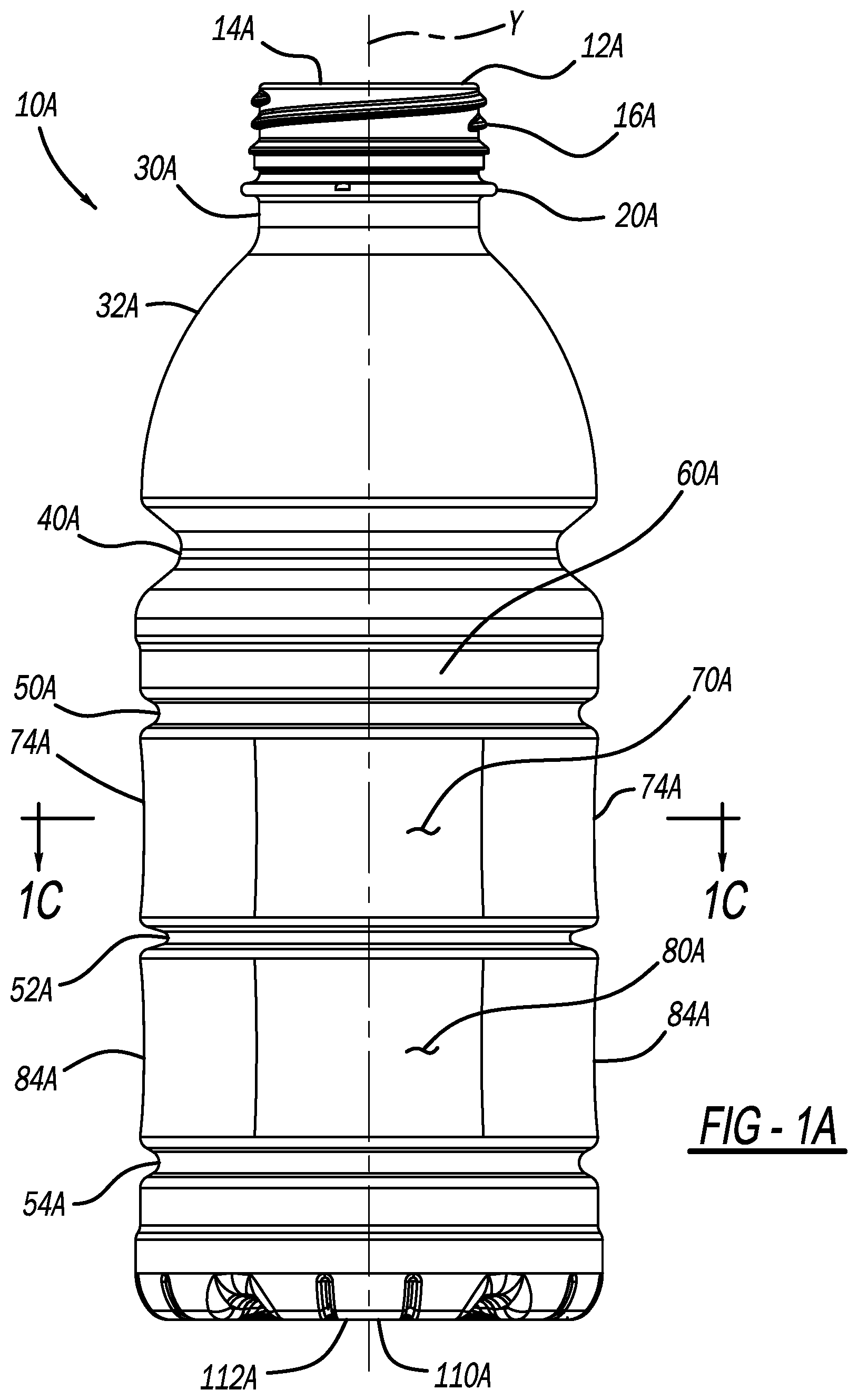
A is a side view of a first polymeric container in accordance with the present disclosure, the first polymeric container is in an as-blown, pre-filled configuration;
B is another side view of the container of A ;
C is a cross-sectional view taken along line 1 C- 1 C of A ;
A is a side view similar to A of the first polymeric container, but with flexible panels thereof contracted in response to a vacuum within the container as a result of filling and capping the container;
B is another side view of the container with flexible panels thereof contracted;
C is a cross-sectional view taken along line 2 C- 2 C of A ;
D is a cross-sectional view taken along line 2 D- 2 D of A ;
E is a cross-sectional view taken along line 2 E- 2 E of B ;
A is a side view similar to A of the first polymeric container, but with flexible panels thereof further contracted in response to additional vacuum within the container as a result of filling and capping the container;
B is another side view of the container with the flexible panels thereof further contracted;
C is a cross-sectional view taken along line 3 C- 3 C of A ;
D is a cross-sectional view taken along line 3 D- 3 D of A ;
E is a cross-sectional view taken along line 3 E- 3 E of B ;
is a side view of the first polymeric container configured with vertically aligned flexible panels that contract at different rates in response to a vacuum within the container as a result of filling and capping the container;
is a side view of the first polymeric container configured with vertically offset flexible panels that contract at different rates in response to a vacuum within the container as a result of filling and capping the container;
A is a side view of a second polymeric container in accordance with the present disclosure, the second polymeric container is in an as-blown, pre-filled configuration;
B is another side view of the second container of A ;
C is a cross-sectional view taken along line 6 C- 6 C of A ;
A is a side view similar to A of the second polymeric container, but with flexible panels thereof contracted in response to a vacuum within the container as a result of filling and capping the container;
B is another side view of the second container with flexible panels thereof contracted;
C is a cross-sectional view taken along line 7 C- 7 C of A ;
D is a cross-sectional view taken along line 7 D- 7 D of A ;
E is a cross-sectional view taken along line 7 E- 7 E of B ;
A is a side view similar to A of the second polymeric container, but with flexible panels thereof further contracted in response to additional vacuum within the container as a result of filling and capping the container;
B is another side view of the second container with the flexible panels thereof further contracted;
C is a cross-sectional view taken along line 8 C- 8 C of A ;
D is a cross-sectional view taken along line 8 D- 8 D of A ;
E is a cross-sectional view taken along line 8 E- 8 E of B ;
is a side view of the second polymeric container configured with vertically aligned flexible panels that contract at different rates in response to a vacuum within the container as a result of filling and capping the container;
is a side view of the second polymeric container configured with vertically offset flexible panels that contract at different rates in response to a vacuum within the container as a result of filling and capping the container;
A is a side view of a third polymeric container in accordance with the present disclosure, the third polymeric container is in an as-blown, pre-filled configuration;
B is another side view of the third container of A ;
C is a cross-sectional view taken along line 11 C- 11 C of A ;
A is a side view similar to A of the third polymeric container, but with flexible panels thereof contracted in response to a vacuum within the container as a result of filling and capping the container;
B is another side view of the third container with flexible panels thereof contracted;
C is a cross-sectional view taken along line 12 C- 12 C of A ;
D is a cross-sectional view taken along line 12 D- 12 D of A ;
E is a cross-sectional view taken along line 12 E- 12 E of B ;
A is a side view similar to A of the third polymeric container, but with flexible panels thereof further contracted in response to additional vacuum within the container as a result of filling and capping the container;
B is another side view of the container with the flexible panels thereof further contracted;
C is a cross-sectional view taken along line 13 C- 13 C of A ;
D is a cross-sectional view taken along line 13 D- 13 D of A ;
E is a cross-sectional view taken along line 13 E- 13 E of B ;
is a side view of the third polymeric container configured with vertically aligned flexible panels that contract at different rates in response to a vacuum within the container as a result of filling and capping the container; and
is a side view of the third polymeric container configured with vertically offset flexible panels that contract at different rates in response to a vacuum within the container as a result of filling and capping the container.
Corresponding reference numerals indicate corresponding parts throughout the several views of the drawings.
DETAILED DESCRIPTION
Example embodiments will now be described more fully with reference to the accompanying drawings.
With initial reference to A and 1 B , an exemplary polymeric container in accordance with the present disclosure is illustrated at reference numeral 10 A. The container 10 A generally includes a finish 12 A at a first end 14 A of the container 10 A. The finish 12 A defines an opening of the container 10 A. At an outer surface of the finish 12 A are threads 16 A. The threads 16 A are configured to cooperate with corresponding threads of a closure to secure the closure to the finish 12 A and close the container 10 A.
Below the finish 12 A is a neck 30 A. Extending from the neck 30 A is a shoulder 32 A. The shoulder 32 A extends to a body 60 A of the container 10 A. Between the shoulder 32 A and the body 60 A is a horizontal rib 40 A. The body 60 A may include any suitable number of additional ribs. For example, the body 60 A may include ribs 50 A, 52 A, and 54 A. The ribs 50 A, 52 A, and 54 A extend entirely around the body 60 A, and each one may be flexible or rigid ribs. In the example illustrated, the rib 52 A is flexible, and the ribs 50 A and 54 A are rigid.
The body 60 A further includes a first flexible panel 70 A and a second flexible panel 80 A, each of which extend around an entirety of the body 60 A. The first and second flexible panels 70 A and 80 B may have any suitable sidewall thickness, such as 0.330 mm or less. The first flexible panel 70 A is between the rib 50 A and the rib 52 A. The second flexible panel 80 A is between the rib 52 A and the rib 54 A. Although two flexible panels 70 A, 80 A are illustrated, any suitable number of flexible panels may be included, such as a single flexible panel or more than two flexible panels. The first and second flexible panels 70 A and 80 A will be described further herein.
The container 10 A further includes a base 110 A at a second end of the container 10 A, which is opposite to the first end 14 A. The base 110 A may be any suitable base, such as any suitable vacuum absorbing base. A longitudinal axis “y” of the container 10 A extends through an axial center of the base 110 A, an axial center of the finish 12 A, and an axial center of the body 60 A.
With continued reference to A and 1 B , and additional reference to C in particular, the first flexible panel 70 A will now be described in additional detail. The first flexible panel 70 A includes a plurality of concave portions 74 A. The concave portions 74 A are spaced apart at regular intervals about an entirety of the flexible panel 70 A and the body 60 A, and thus generally oscillate about the flexible panel 70 A and around the container 10 A. The concave portions 74 A curve inward towards the longitudinal axis y, and are concave at an outer surface of the container 10 . Between the concave portions 74 A are vertically extending columns 72 A. The vertically extending ribs 72 A extend parallel to, or generally parallel to, the longitudinal axis y prior to the container 10 A being filled and capped. The first flexible panel 70 A may have any suitable number of concave portions 74 A and vertically extending columns 72 A. In the examples illustrated, the container 10 A has six concave portions 74 A and six vertically extending columns 72 A. However, the container 10 A may include 4-8 of each one of the concave portions 74 A and vertically extending columns 72 A, with there being an equal number of concave portions 74 A and vertically extending columns 72 A.
C illustrates a reference circle R, which touches, or nearly touches, each of the vertically extending columns 72 A. The concave portions 74 A are between the reference circle R and the longitudinal axis y. The concave portions 74 A are recessed below the reference circle R by 0.60 mm, or about 0.60 mm. Thus, a distance D1A between the vertically extending columns 72 A and the longitudinal axis y is greater than a distance D2A between the concave portions 74 A and the longitudinal axis y. The flexible panel 70 A has a first diameter between opposing vertically extending columns 72 A, which is larger than a second diameter between opposing concave portions 74 A. For example, the first diameter between opposing vertically extending columns 72 A may be about 72.75 mm, and the second diameter between opposing vertically extending columns 72 A may be 0.25 mm-2.5 mm or less, such as about 0.60 mm less. A radius of one of the vertically extending columns 72 A is half a maximum diameter of the container 10 A.
The second flexible panel 80 A is substantially similar to, or the same as, the first flexible panel 70 A. The rib 52 A separates the first and second flexible panels 70 A, 80 A. The rib 52 A may be flexible as illustrated in A- 5 , which absorbs vacuum. The second flexible panel 80 A includes concave portions 84 A, which are substantially similar to, or the same as, the concave portions 74 A. The second flexible panel 80 A further includes vertically extending columns 82 A, which are substantially similar to, or the same as, the vertically extending columns 72 A. The concave portions 74 A, 84 A may be vertically aligned, or offset. Similarly, the vertically extending columns 72 A, 82 A may be vertically aligned, or offset.
The overall height of the first flexible panel 70 A and/or the second flexible panel 80 A may be 20%-50% of a total label panel height of the container 10 A. The label panel may extend from about the rib 50 B to the rib 54 B. The concave portions 74 A may be 40%-90% of a total label panel surface area.
The concave portions 74 A and 84 A are configured to flex inwards towards the axial center and longitudinal axis y in response to a vacuum within the container 10 A resulting from filling and capping the container 10 A. For example and as illustrated in A- 2 E , the concave portions 74 A and 84 A flex inwards and become more concave at 74 A′ and 84 A′. The inwardly flexed concave portions 74 A′ and 84 A′ assume a generally round shape. In response to the vacuum, the vertically extending columns 72 A flex outward and become convex at 72 A′. With reference to C- 2 E in particular, the vertically extending columns flex outward to 72 A′ such that distance D1A′ is greater than D1A. The concave portions flex inward to 74 A′ such that distance D2A′ is less than D2A. Also, the base 110 A flexes inward to 110 A′ to absorb the vacuum, as illustrated in D and 2 E .
As the vacuum within the container 10 A increases, the concave portions 74 A′ and 84 A′ flex further inward towards the longitudinal axis y to positions 74 A″ and 84 A″ illustrated in A- 3 E . Under this further increased vacuum, the concave portions 74 A″ and 84 A″ are configured to assume a generally hexagonal shape. Under this further increased vacuum, the vertically extending columns move to 72 A″ and 82 A″. Distance D1A″ from the longitudinal axis y to the vertically extending columns 72 A″ (and to columns 82 A″) is less than distance D1A′. Distance D2A″ from the longitudinal axis y to the concave portions 74 A″ (and to concave portions 84 A″) is less than distance D2A′.
With reference to , the flexible panels 70 A and 80 A can be configured such that different ones of the concave portions 74 A and 84 A respectively flex more towards the longitudinal axis y than others. For example, some of the concave portions 74 A may be configured to flex to 74 A′, while others may be configured to flex to 74 A″. The concave portions 74 A′ and 74 A″ may alternate around the flexible panel 70 A. The flexible panel 80 A may be configured in the same manner or a similar manner.
In the example of , the vertically aligned concave portions 74 A′ and 84 A″ (as well as 74 A″ and 84 A′) are configured to flex inward at different rates in response to a vacuum within the container 10 A. In the example of , vertically aligned concave portions 74 A′ and 84 A′ (as well as 74 A″ and 84 A″) are configured to flex inward at the same rate, while vertically offset concave portions 74 A′ and 84 A″ (as well as 74 A″ and 84 A′) are configured to flex inward at different rates.
A- 10 illustrate another exemplary container in accordance with the present disclosure at reference numeral 10 B. Features of the container 10 B that are the same as, or substantially the same as, the container 10 A are identified in the drawings with the same reference numerals, but include the suffix “B” instead of “A.” The description of the container 10 A equally applies to the description of the container 10 B at least with respect to these like features.
The rib 52 B of the container 10 B is rigid, which is in contrast to the flexible rib 52 A of the container 10 A. As a result, the flexible panels 70 B and 80 B move more than the flexible panels 70 A and 80 A in response to a vacuum within the container 10 B. Thus, the difference between D1B and D1B′ is greater than the different between D1A and D1A′; the difference between D2B and D2B′ is greater than the difference between D2A and D2A′; the difference between D1B′ and D1B″ is greater than the difference between D1A′ and D1A″; and the difference between D2B′ and D2B″ is greater than the difference between D2A′ and D2A″.
A- 15 illustrate another exemplary container in accordance with the present disclosure at reference numeral 10 C. Features of the container 10 C that are the same as, or substantially the same as, the container 10 A are identified in the drawings with the same reference numerals, but include the suffix “C” instead of “A.” The description of the container 10 A equally applies to the description of the container 10 C at least with respect to these like features.
Unlike the containers 10 A and 10 B, the container 10 C does not include the ribs 50 A and 54 A. The container 10 C does include rib 52 C, which is a rigid rib like the rib 52 B. As a result of not including the ribs 50 A, 54 A, the oscillations formed at the flexible panels 70 C will absorb a greater amount of internal vacuum.
The present disclosure advantageously solves many problems associated with hot-filled thermoplastic containers by creating controlled modes of failure at the flexible panels 70 A, 80 A, which allows for fewer ribs to be utilized by the containers 10 A, 10 B, 10 C, and a reduction in material thickness and weight. The resulting benefits are greater controlled vacuum performance, and higher topload at the first end 14 A, 14 B, 14 C due to the capability to reduce or eliminate horizontal ribs in the container sidewall. The aforementioned benefits can also translate to higher efficiency, low vacuum, and aseptic applications, where complex, deep ribbed geometry can create greater dwell times in the sterilization chamber.
The oscillations formed at the flexible panels 70 A, 70 B, 70 C, 80 A, 80 B, 80 C due to the alternating concave portions 74 A, 74 B, 74 C and columns 72 A, 72 B, 72 C allow for acceptance of greater amounts of internal vacuum forces, which allows for a reduction of material weight, ribs or other sidewall features that can compromise topload, perpendicularity, or container shape. In lightweight hotfill containers, base supported filling has a minimum requirement for topload. Previous lightweight designs (>0.013″) have required horizontal structural ribs that increase hoop strength and resist vacuum but reduce topload. The addition of the oscillations allows for ribs to be removed from the sidewall, due to their ability to uptake additional vacuum, thus increasing topload while enabling lower levels of material thickness. The reduction of ribs also leads to lower risk of container lean caused by uneven collapsing of ribs
In addition to the structural support, the capability to reduce the number of ribs reduces the amount of aggressive protruding or receding features (such as ribs) in an aseptic package. Aseptic sterilization of packaging requires a calculated dwell time to both kill the appropriate level of microorganisms, and rinse and remove the sterilant from the packaging prior to fill. Reducing the amount of aggressive protruding or receding features can also reduce the dwell time, increasing the efficiency of aseptic sterilization. The oscillations also provide ergonomic gripping areas, accommodating various hand sizes and strength.
The foregoing description of the embodiments has been provided for purposes of illustration and description. It is not intended to be exhaustive or to limit the disclosure. Individual elements or features of a particular embodiment are generally not limited to that particular embodiment, but, where applicable, are interchangeable and can be used in a selected embodiment, even if not specifically shown or described. The same may also be varied in many ways. Such variations are not to be regarded as a departure from the disclosure, and all such modifications are intended to be included within the scope of the disclosure.
Example embodiments are provided so that this disclosure will be thorough, and will fully convey the scope to those who are skilled in the art. Numerous specific details are set forth such as examples of specific components, devices, and methods, to provide a thorough understanding of embodiments of the present disclosure. It will be apparent to those skilled in the art that specific details need not be employed, that example embodiments may be embodied in many different forms and that neither should be construed to limit the scope of the disclosure. In some example embodiments, well-known processes, well-known device structures, and well-known technologies are not described in detail.
The terminology used herein is for the purpose of describing particular example embodiments only and is not intended to be limiting. As used herein, the singular forms “a,” “an,” and “the” may be intended to include the plural forms as well, unless the context clearly indicates otherwise. The terms “comprises,” “comprising,” “including,” and “having,” are inclusive and therefore specify the presence of stated features, integers, steps, operations, elements, and/or components, but do not preclude the presence or addition of one or more other features, integers, steps, operations, elements, components, and/or groups thereof. The method steps, processes, and operations described herein are not to be construed as necessarily requiring their performance in the particular order discussed or illustrated, unless specifically identified as an order of performance. It is also to be understood that additional or alternative steps may be employed.
When an element or layer is referred to as being “on,” “engaged to,” “connected to,” or “coupled to” another element or layer, it may be directly on, engaged, connected or coupled to the other element or layer, or intervening elements or layers may be present. In contrast, when an element is referred to as being “directly on,” “directly engaged to,” “directly connected to,” or “directly coupled to” another element or layer, there may be no intervening elements or layers present. Other words used to describe the relationship between elements should be interpreted in a like fashion (e.g., “between” versus “directly between,” “adjacent” versus “directly adjacent,” etc.). As used herein, the term “and/or” includes any and all combinations of one or more of the associated listed items.
Although the terms first, second, third, etc. may be used herein to describe various elements, components, regions, layers and/or sections, these elements, components, regions, layers and/or sections should not be limited by these terms. These terms may be only used to distinguish one element, component, region, layer or section from another region, layer or section. Terms such as “first,” “second,” and other numerical terms when used herein do not imply a sequence or order unless clearly indicated by the context. Thus, a first element, component, region, layer or section discussed below could be termed a second element, component, region, layer or section without departing from the teachings of the example embodiments.
Spatially relative terms, such as “inner,” “outer,” “beneath,” “below,” “lower,” “above,” “upper,” and the like, may be used herein for ease of description to describe one element or feature's relationship to another element(s) or feature(s) as illustrated in the figures. Spatially relative terms may be intended to encompass different orientations of the device in use or operation in addition to the orientation depicted in the figures. For example, if the device in the figures is turned over, elements described as “below” or “beneath” other elements or features would then be oriented “above” the other elements or features. Thus, the example term “below” can encompass both an orientation of above and below. The device may be otherwise oriented (rotated 90 degrees or at other orientations) and the spatially relative descriptors used herein interpreted accordingly.
Figures (20)
Citations
This patent cites (23)
- US5690244
- US6575320
- US6763969
- US6935525
- US2002/0104820
- US2003/0015491
- US2005/0269284
- US2009/0283495
- US2010/0206892
- US2011/0108515
- US2011/0217494
- US2011/0220668
- US2012/0097635
- US2013/0228249
- US2014/0166609
- US2017/0225863
- US2017/0334628
- US2021/0323745
- US2022/0097912
- US98002868
- US2003531774
- USWO-2004069669
- USWO-2004074116