Contactless Power Transmission System Capable of Controlling Power Transmitter Apparatus to Stably Supply Load Device with Required Power
Abstract
A control circuit controls a power supply circuit to generate transmitting power having a frequency varying within a frequency range. The control circuit determines a stably transmitting frequency based on a detected output voltage of a power receiver apparatus, the stably transmitting frequency indicating a frequency of the transmitting power at which dependency of the output voltage on a load value of the power receiver apparatus is at least locally minimized within the frequency range. The control circuit determines a transmitting voltage based on the detected output voltage, the transmitting voltage indicating a voltage of the transmitting power at which the output voltage reaches a target voltage when generating transmitting power having the stably transmitting frequency. The control circuit controls the power supply circuit to generate transmitting power having the stably transmitting frequency and the transmitting voltage.
Claims (13)
1. A contactless power transmission system including a power transmitter apparatus and a power receiver apparatus, the contactless power transmission system transmitting power in a contactless manner from the power transmitter apparatus to the power receiver apparatus, wherein the power transmitter apparatus comprises: a transmitting coil; a power supply circuit configured to generate transmitting power having a variable voltage and a variable frequency, and supply the transmitting power to the transmitting coil; and a controller apparatus, wherein the power receiver apparatus comprises: a receiving coil; a voltage detector circuit configured to detect an output voltage of the power receiver apparatus; and a power-receiver communication device communicatively connected to the power transmitter apparatus, and configured to transmit a detected value of the output voltage of the power receiver apparatus to the power transmitter apparatus, wherein the controller apparatus comprises: a power-transmitter communication device communicatively connected to the power receiver apparatus, and configured to receive the detected value of the output voltage of the power receiver apparatus from the power receiver apparatus; and a first control circuit configured to control the power supply circuit based on the detected value of the output voltage of the power receiver apparatus, wherein the first control circuit is further configured to: control the power supply circuit to generate transmitting power having a frequency varying within a predetermined frequency range, receive the detected value of the output voltage of the power receiver apparatus from the power receiver apparatus using the power-transmitter communication device, the detected value being detected in the power receiver apparatus when generating the transmitting power using the power supply circuit, determine a stably transmitting frequency based on the detected value of the output voltage of the power receiver apparatus, the stably transmitting frequency indicating a frequency of the transmitting power at which dependency of the output voltage of the power receiver apparatus on a load value of the power receiver apparatus is at least locally minimized within the frequency range, determine a transmitting voltage based on the detected value of an output voltage of the power receiver apparatus, the transmitting voltage indicating a voltage of the transmitting power at which the output voltage of the power receiver apparatus reaches a predetermined target voltage when generating transmitting power having the stably transmitting frequency, and control the power supply circuit to generate transmitting power having the stably transmitting frequency and the transmitting voltage, wherein the power receiver apparatus further comprises: a load device having a variable load value: a first load element having a first load value; a second load element having a second load value larger than the first load value; and a first switch circuit configured to selectively supply the output voltage of the power receiver apparatus to one of the load device, the first load element, and the second load element, wherein the first control circuit is further configured to: when performing normal power transmission, transmit a control signal to the power receiver apparatus using the power-transmitter communication device, the control signal being provided for switching the first switch circuit to supply the output voltage of the power receiver apparatus to the load device, and when determining a frequency of the transmitting power, transmit a control signal to the power receiver apparatus using the power-transmitter communication device, the control signal being provided for switching the first switch circuit to supply the output voltage of the power receiver apparatus to the first or second load element, and wherein the first control circuit is further configured to: obtain a first voltage indicating a frequency characteristic of the output voltage of the power receiver apparatus, based on the detected value of the output voltage of the power receiver apparatus, when the output voltage of the power receiver apparatus is supplied to the first load element, obtain a second voltage indicating a frequency characteristic of the output voltage of the power receiver apparatus, based on the detected value of the output voltage of the power receiver apparatus, when the output voltage of the power receiver apparatus is supplied to the second load element, and determine a frequency of the transmitting power at which a difference between the first voltage and the second voltage is minimized, as the stably transmitting frequency.
Show 12 dependent claims
2. The contactless power transmission system as claimed in claim 1 , wherein, when the detected value of the output voltage of the power receiver apparatus changes by a value larger than a first threshold from the detected value obtained when determining the stably transmitting frequency and the transmitting voltage, the first control circuit redetermines the stably transmitting frequency and the transmitting voltage based on the detected value of the output voltage of the power receiver apparatus.
3. The contactless power transmission system as claimed in claim 1 , the controller apparatus further comprising a coupling coefficient estimator configured to estimate a coupling coefficient of the transmitting coil and the receiving coil, wherein, when the coupling coefficient changes by a value larger than a second threshold from the detected value obtained when determining the stably transmitting frequency and the transmitting voltage, the first control circuit redetermines the stably transmitting frequency and the transmitting voltage based on the detected value of the output voltage of the power receiver apparatus.
4. The contactless power transmission system as claimed in claim 3 , the controller apparatus further comprising: a first auxiliary coil electromagnetically coupled to the transmitting coil; a first detector configured to detect a value of a current or a voltage generated in the first auxiliary coil; and a second detector configured to detect a current flowing through the transmitting coil, wherein the coupling coefficient estimator estimates the coupling coefficient based on values detected by the first detector and the second detector.
5. The contactless power transmission system as claimed in claim 4 , wherein the coupling coefficient estimator estimates a first coupling coefficient between the transmitting coil and the receiving coil based on the value of the current or voltage generated in the first auxiliary coil, and estimates a second coupling coefficient between the transmitting coil and the receiving coil based on a value of the current flowing through the transmitting coil, and wherein the first control circuit is further configured to: when a difference between the first coupling coefficient and the second coupling coefficient is equal to or less than a second threshold, control the power supply circuit to generate the transmitting power having the stably transmitting frequency and the transmitting voltage, and when the difference between the first coupling coefficient and the second coupling coefficient exceeds the second threshold, control the power supply circuit to stop transmission of the power to the power receiver apparatus.
6. The contactless power transmission system as claimed in claim 3 , the controller apparatus further comprising: a first auxiliary coil electromagnetically coupled to the transmitting coil; and a detector configured to detect a value of a current or a voltage generated in the first auxiliary coil, wherein the coupling coefficient estimator estimates the coupling coefficient based on the value of the current or voltage generated in the first auxiliary coil.
7. The contactless power transmission system as claimed in claim 3 , the controller apparatus further comprising a detector configured to detect a value of a current flowing through the transmitting coil, wherein the coupling coefficient estimator estimates the coupling coefficient based on the value of the current flowing through the transmitting coil.
8. The contactless power transmission system as claimed in claim 1 , wherein the power supply circuit includes a full-bridge inverter or a half-bridge inverter.
9. The contactless power transmission system as claimed in claim 1 , wherein at least one of the power transmitter apparatus and the power receiver apparatus further comprises a capacitor connected to and resonating with the transmitting coil or the receiving coil, and wherein capacitance of the capacitor is set such that a frequency at which the dependency of the output voltage of the power receiver apparatus on the load value of the power receiver apparatus is at least locally minimized is included within a predetermined frequency range.
10. The contactless power transmission system as claimed in claim 9 , wherein the power transmitter apparatus comprises a first capacitor connected to and resonating with the transmitting coil, the first capacitor having first capacitance, and wherein the power receiver apparatus comprises a second capacitor connected to and resonating with the receiving coil, the second capacitor having second capacitance different from the first capacitance.
11. The contactless power transmission system according to claim 1 , wherein the power receiver apparatus further includes a rectifier circuit configured to rectify a voltage generated in the receiving coil, and wherein the rectifier circuit is a full-wave rectifier circuit of diodes, a voltage-doubler rectifier circuit of diodes, a full-wave rectifier circuit of switching elements, or a voltage-doubler rectifier circuit of switching elements.
12. The contactless power transmission system as claimed in claim 1 , wherein the power receiver apparatus further comprises: a second control circuit configured to switch the first switch circuit to supply the output voltage of the power receiver apparatus to the load element, when the output voltage of the power receiver apparatus detected by the voltage detector circuit exceeds a fourth threshold.
13. The contactless power transmission system as claimed in claim 1 , wherein the power receiver apparatus further comprises: a second auxiliary coil electromagnetically coupled to the transmitting coil; a second switch circuit; a third load element connected to the second auxiliary coil via the second switch circuit; and a second control circuit configured to turn on the second switch circuit, when the output voltage of the power receiver apparatus detected by the voltage detector circuit exceeds a fourth threshold.
Full Description
Show full text →
CROSS REFERENCE TO RELATED APPLICATIONS
This is the U.S. national stage of application No. PCT/JP2019/030776, filed on Aug. 5, 2019. Priority is claimed and the disclosure of which is also incorporated herein by reference.
TECHNICAL FIELD
The present disclosure relates to a controller apparatus of a power transmitter apparatus configured to transmit power to a power receiver apparatus in a contactless manner. The present disclosure also relates to a power transmitter apparatus provided with such a controller apparatus. The present disclosure also relates to a contactless power transmission system including such a power transmitter apparatus.
BACKGROUND ART
There has been known a contactless power transmission system configured to transmit power in a contactless manner from a power transmitter apparatus connected to a power supply, to a power receiver apparatus including a load device, such as a rechargeable battery.
For example, Patent Document 1 discloses a wireless power transmission system including a power receiver apparatus, the power receiver apparatus being provided with a first power converter that rectifies an AC voltage received through a coil into a DC voltage, and a second power converter that converts the DC voltage rectified by the first power converter into an arbitrary DC voltage or AC voltage. A controller of the power receiver apparatus controls efficiency of power transmission with the power transmitter apparatus using one of the first and second power converters, and controls power received from the power transmitter apparatus using the other of the first and second power converters.
CITATION LIST
Patent Documents
•
• PATENT DOCUMENT 1: Japanese Patent Laid-Open No. JP 2017-093094 A
SUMMARY OF INVENTION
Technical Problem
In general, power consumption or current consumption of a load device varies over time. Accordingly, when a power transmitter apparatus transmits power to a power receiver apparatus in a contactless manner, a voltage applied to the load device (referred to as an “output voltage of the power receiver apparatus” in this specification) may vary in accordance with to variations of power consumption or current consumption of the load device (referred to as a “load value of the load device” in this specification).
In order to supply the load device with its required voltage from the power receiver apparatus, for example, as disclosed in Patent Document 1, it is considered to provide the power receiver apparatus with an additional power converter (such as a DC/DC converter or a DC/AC converter). However, in the case where the power receiver apparatus is provided with the additional power converter (such as a DC/DC converter), the size, weight, and cost of the power receiver apparatus increase, and the efficiency decreases. Accordingly, it is required to control the power transmitter apparatus to stably supply the load device with its required voltage, without need of an extra circuit (such as a DC/DC converter) in the power receiver apparatus.
An object of the present disclosure is to provide a controller apparatus of a power transmitter apparatus capable of controlling the power transmitter apparatus to stably supply a load device with its required voltage, without need of an extra circuit in a power receiver apparatus.
Further objects of the present disclosure are to provide a power transmitter apparatus provided with such a controller apparatus, and provide a contactless power transmission system including such a power transmitter apparatus.
Solution to Problem
In order to solve the above-described problems, a controller apparatus of a power transmitter apparatus, a power transmitter apparatus, and a contactless power transmission system according to aspects of the present disclosure are configured as follows.
According to an aspect of the present disclosure, a controller apparatus of a power transmitter apparatus is provided for transmitting power in a contactless manner to a power receiver apparatus with a receiving coil. The power transmitter apparatus is provided with: a transmitting coil; and a power supply circuit configured to generate transmitting power having a variable voltage and a variable frequency, and supply the transmitting power to the transmitting coil. The controller apparatus is provided with: a first communication device communicatively connected to the power receiver apparatus, and configured to receive a detected value of an output voltage of the power receiver apparatus from the power receiver apparatus; and a first control circuit configured to control the power supply circuit based on the detected value of the output voltage of the power receiver apparatus. The first control circuit is configured to control the power supply circuit to generate transmitting power having a frequency varying within a predetermined frequency range. The first control circuit is configured to receive the detected value of the output voltage of the power receiver apparatus from the power receiver apparatus using the first communication device, the detected value being detected in the power receiver apparatus when generating the transmitting power using the power supply circuit. The first control circuit is configured to determine a stably transmitting frequency based on the detected value of the output voltage of the power receiver apparatus, the stably transmitting frequency indicating a frequency of the transmitting power at which dependency of the output voltage of the power receiver apparatus on a load value of the power receiver apparatus is at least locally minimized within the frequency range. The first control circuit is configured to determine a transmitting voltage based on the detected value of an output voltage of the power receiver apparatus, the transmitting voltage indicating a voltage of the transmitting power at which the output voltage of the power receiver apparatus reaches a predetermined target voltage when generating transmitting power having the stably transmitting frequency. The first control circuit is configured to control the power supply circuit to generate transmitting power having the stably transmitting frequency and the transmitting voltage.
According to an aspect of the present disclosure, a power transmitter apparatus is provided with: a transmitting coil; a power supply circuit configured to generate transmitting power having a variable voltage and a variable frequency, and supply the transmitting power to the transmitting coil; and the controller apparatus of the power transmitter apparatus.
According to an aspect of the present disclosure, a contactless power transmission system includes: the power transmitter apparatus; and a power receiver apparatus. The power receiver apparatus is provided with: a receiving coil, a voltage detector circuit configured to detect an output voltage of the power receiver apparatus, and a second communication device communicatively connected to the power transmitter apparatus, and configured to transmit a detected value of the output voltage of the power receiver apparatus to the power transmitter apparatus.
Advantageous Effects of Invention
According to the present disclosure, it is possible to control the power transmitter apparatus to stably supply the load device with its required voltage, without need of an extra circuit in the power receiver apparatus.
BRIEF DESCRIPTION OF DRAWINGS
is a block diagram illustrating a configuration of a contactless power transmission system according to a first embodiment.
is a graph illustrating frequency characteristics of an output voltage of a contactless power transmission system according to a comparative example.
is a graph illustrating frequency characteristics of an output voltage of the contactless power transmission system of .
is a diagram for explaining variations in a voltage V 4 of a power receiver apparatus 20 by controlling a voltage V 0 of a power transmitter apparatus 10 in the contactless power transmission system of .
is a circuit diagram illustrating a configuration of an inverter 13 of .
is a circuit diagram illustrating a configuration of a rectifier circuit 22 of .
is a perspective view illustrating arrangement of a transmitting coil L 1 and a receiving coil L 2 of .
is a flowchart illustrating power transmitting process performed by a control circuit 11 of the power transmitter apparatus 10 of .
is a flowchart illustrating a subroutine of step S 2 of .
is a flowchart illustrating power receiving process performed by a control circuit 21 of the power receiver apparatus 20 of .
is a diagram schematically illustrating waveforms of voltages V 1 , V 4 , and V 5 in the contactless power transmission system of .
is a diagram for explaining search and determination of a switching frequency fsw in steps S 13 to S 14 of .
is an equivalent circuit diagram illustrating a schematic configuration of the contactless power transmission system of .
is a diagram for explaining how to determine capacitances of capacitors C 1 , C 2 of .
is a perspective view illustrating another arrangement of the transmitting coil L 1 and the receiving coil L 2 of .
is a diagram illustrating a configuration with the capacitor C 1 of the power transmitter apparatus 10 of removed.
is a diagram illustrating a configuration with the capacitor C 2 of the power receiver apparatus 20 of removed.
is a circuit diagram illustrating a modified embodiment of the inverter 13 of .
is a circuit diagram illustrating a first modified embodiment of the rectifier circuit 22 of .
is a circuit diagram illustrating a second modified embodiment of the rectifier circuit 22 of .
is a circuit diagram illustrating a third modified embodiment of the rectifier circuit 22 of .
is a block diagram illustrating a configuration of a contactless power transmission system according to a second embodiment.
is a flowchart illustrating subroutine of power controlling process performed by a control circuit 11 of the power transmitter apparatus 10 of .
is a flowchart illustrating subroutine of step S 41 of .
is a flowchart illustrating subroutine of step S 42 of .
is a flowchart illustrating power receiving process performed by a control circuit 21 B of the power receiver apparatus 20 B of .
is a diagram for explaining determination of a voltage V 5 and a switching frequency fsw in step S 43 of .
is a block diagram illustrating a configuration of a contactless power transmission system according to a third embodiment.
is a flowchart illustrating subroutine of power controlling process performed by a control circuit 11 of the power transmitter apparatus 10 of .
is a flowchart illustrating power receiving process performed by a control circuit 21 C of the power receiver apparatus 20 C of .
is a block diagram illustrating a configuration of a contactless power transmission system according to a modified embodiment of the third embodiment.
is a diagram schematically illustrating waveforms of voltages V 1 , V 2 in the contactless power transmission system of .
is a block diagram illustrating a configuration of a contactless power transmission system according to a fourth embodiment.
is a perspective view illustrating arrangement of a transmitting coil L 1 , a receiving coil L 2 , and an auxiliary coil L 3 of .
is a diagram illustrating an application example of the contactless power transmission system of .
is a graph illustrating an example of variations in the magnitude of a current I 3 generated in the auxiliary coil L 3 and detected by a detector 15 of .
is a graph illustrating an example of variations in the magnitude of a current I 1 flowing through the transmitting coil L 1 and detected by a detector 16 of .
is a table illustrating an example of coupling coefficient k 12 of the transmitting coil L 1 and the receiving coil L 2 , the coupling coefficient k 12 being calculated with respect to the current I 1 flowing through the transmitting coil L 1 of , and the current I 3 generated in the auxiliary coil L 3 of .
is a flowchart illustrating power transmitting process performed by a control circuit 11 E of the power transmitter apparatus 10 E of .
is a flowchart illustrating subroutine of step S 112 of .
is a flowchart illustrating power receiving process performed by a control circuit 21 E of the power receiver apparatus 20 E of .
is a diagram schematically illustrating waveforms of voltages V 1 , V 3 and currents I 1 , I 3 in the contactless power transmission system of .
is an equivalent circuit diagram illustrating a schematic configuration of the contactless power transmission system of .
is a block diagram illustrating a configuration of a contactless power transmission system according to a fifth embodiment.
is a flowchart illustrating subroutine of power controlling process performed by a control circuit 11 F of the power transmitter apparatus 10 F of .
is a block diagram illustrating a configuration of a contactless power transmission system according to a sixth embodiment.
is a flowchart illustrating subroutine of power controlling process performed by a control circuit 11 G of the power transmitter apparatus 10 G of .
is a block diagram illustrating a configuration of a contactless power transmission system according to a seventh embodiment.
is a flowchart illustrating subroutine of power controlling process performed by a control circuit 11 E of the power transmitter apparatus 10 E of .
is a flowchart illustrating power receiving process performed by a control circuit 21 of the power receiver apparatus 20 of .
is a block diagram illustrating a configuration of a contactless power transmission system according to an eighth embodiment.
is a flowchart illustrating subroutine of power controlling process performed by a control circuit 11 F of the power transmitter apparatus 10 F of .
is a block diagram illustrating a configuration of a contactless power transmission system according to a ninth embodiment.
is a flowchart illustrating subroutine of power controlling process performed by a control circuit 11 G of the power transmitter apparatus 10 G of .
is a block diagram illustrating a configuration of a contactless power transmission system according to a tenth embodiment.
is a perspective view illustrating arrangement of a transmitting coil L 1 , a receiving coil L 2 , and an auxiliary coil L 4 of .
is a flowchart illustrating power receiving process performed by a control circuit 21 H of the power receiver apparatus 20 H of .
DESCRIPTION OF EMBODIMENTS
Embodiments according to one aspect of the present disclosure (hereinafter, also referred to as “the present embodiment”) will be described below with reference to the drawings. In the drawings, the same reference signs denote similar components.
Application Example
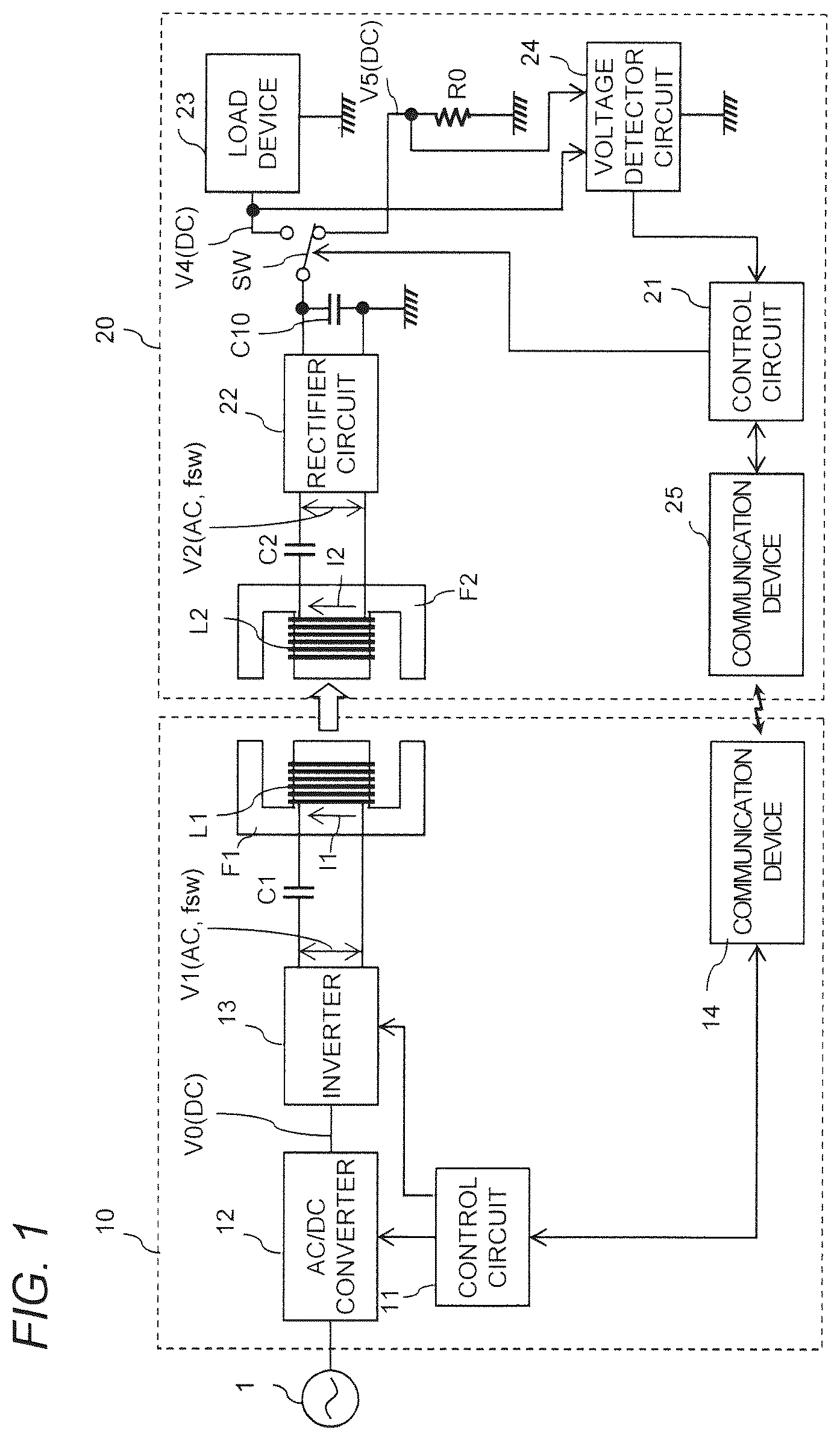
is a block diagram illustrating a configuration of a contactless power transmission system according to a first embodiment. The contactless power transmission system of includes a power transmitter apparatus 10 and a power receiver apparatus 20 , and the power transmitter apparatus 10 transmits power to the power receiver apparatus 20 in a contactless manner.
The power transmitter apparatus 10 is provided with at least a control circuit 11 , an AC/DC converter 12 , an inverter 13 , a communication device 14 , and a transmitting coil (power transmitting coil) L 1 .
The control circuit 11 controls overall operations of the power transmitter apparatus 10 .
The AC/DC converter 12 converts an AC voltage inputted from an AC power supply 1 , into a DC voltage V 0 having a variable magnitude under the control of the control circuit 11 . The inverter 13 operates at a variable switching frequency fsw under the control of the control circuit 11 , and converts the DC voltage V 0 inputted from the AC/DC converter 12 , into an AC voltage V 1 . The voltage V 1 is applied to the transmitting coil L 1 . Here, an amplitude of the voltage V 1 is equal to the magnitude of the voltage V 0 .
In the present specification, the AC/DC converter 12 and the inverter 13 are also collectively referred to as a “power supply circuit”. In other words, the power supply circuit generates transmitting power having a variable voltage and a variable frequency, and supplies the transmitting power to the transmitting coil L 1 .
When the power transmitter apparatus 10 transmits power to the power receiver apparatus 20 , the transmitting coil L 1 is electromagnetically coupled to a receiving coil L 2 of the power receiver apparatus 20 (described below).
The communication device 14 is communicatively connected to the power receiver apparatus 20 , and receives a detected value of an output voltage (described below) of the power receiver apparatus 20 from the power receiver apparatus 20 .
The control circuit 11 controls the AC/DC converter 12 and the inverter 13 based on the detected value of the output voltage of the power receiver apparatus 20 . In particular, the control circuit 11 controls the magnitude of the voltage V 0 outputted from the AC/DC converter 12 , and the switching frequency fsw of the inverter 13 .
The power receiver apparatus 20 is provided with at least a receiving coil (power receiving coil) L 2 , a voltage detector circuit 24 , and a communication device 25 .
When the power transmitter apparatus 10 transmits power to the power receiver apparatus 20 , the receiving coil L 2 is electromagnetically coupled to the transmitting coil L 1 of the power transmitter apparatus 10 .
A load device 23 is provided inside or outside the power receiver apparatus 20 . The load device 23 includes, for example, a rechargeable battery, a motor, an electric circuit, and/or an electronic circuit. Power received from the power transmitter apparatus 10 via the receiving coil L 2 is supplied to the load device 23 .
In this specification, the power consumption or the current consumption of the load device 23 is also referred to as a “load value of the load device”.
In general, the load device 23 has a variable load value varying over time. For example, in the case where the load device 23 is a rechargeable battery, the current flowing through the load device 23 varies in accordance with the state of charge of the rechargeable battery. Accordingly, the voltage applied to the load device 23 may vary in accordance with the variations of the load value of the load device 23 . In addition, the voltage applied to load device 23 varies in accordance with a coupling coefficient k 12 of the transmitting coil L 1 and the receiving coil L 2 (that is, a distance between the transmitting coil L 1 and the receiving coil L 2 ). On the other hand, the control circuit 11 of the power transmitter apparatus 10 controls the AC/DC converter 12 and the inverter 13 based on the detected value of the output voltage of the power receiver apparatus 20 (that is, the voltage applied to load device 23 ), as described above. In this case, it is desired that the control circuit 11 of the power transmitter apparatus 10 obtains the detected value of the output voltage of the power receiver apparatus 20 , which depends on the coupling coefficient k 12 of the transmitting coil L 1 and the receiving coil L 2 , but which does not depend on the variations of the load value of the load device 23 . Accordingly, the power receiver apparatus 20 may be provided with a load element R 0 having a predetermined load value, and detect a voltage V 5 applied to the load element R 0 as the output voltage of power receiver apparatus 20 , instead of a voltage V 4 applied to the load device 23 .
In this specification, the voltage V 4 applied to the load device 23 , or the voltage V 5 applied to the load element R 0 is also referred to as an “output voltage of the power receiver apparatus”.
The voltage detector circuit 24 detects the output voltage of the power receiver apparatus 20 . Although the voltage detector circuit 24 detects both the voltages V 4 and V 5 in the example of , only one of the voltages V 4 and V 5 may be detected.
The communication device 25 is communicatively connected to the power transmitter apparatus 10 , and transmits a detected value of the output voltage of the power receiver apparatus 20 to the power transmitter apparatus 10 .
In this specification, the control circuit 11 of the power transmitter apparatus 10 is also referred to as a “first control circuit”. In this specification, the communication device 14 of the power transmitter apparatus 10 is also referred to as a “first communication device”, and the communication device 25 of the power receiver apparatus 20 is also referred to as a “second communication device”.
The control circuit 11 of the power transmitter apparatus 10 controls the AC/DC converter 12 and the inverter 13 to generate transmitting power having a frequency varying within a predetermined frequency range. The control circuit 11 receives a detected value of the output voltage of the power receiver apparatus 20 from the power receiver apparatus 20 using the communication device 14 , the detected value being detected in the power receiver apparatus 20 when generating the transmitting power using the AC/DC converter 12 and the inverter 13 . The control circuit 11 determines a stably transmitting frequency based on the detected value of the output voltage of the power receiver apparatus 20 , the stably transmitting frequency indicating a frequency of the transmitting power at which dependency of the output voltage of the power receiver apparatus 20 on the load value of the power receiver apparatus 20 is at least locally minimized within the predetermined frequency range. The control circuit 11 determines a transmitting voltage based on the detected value of the output voltage of the power receiver apparatus 20 , the transmitting voltage indicating a voltage of the transmitting power at which the output voltage of the power receiver apparatus 20 reaches a predetermined target voltage when generating the transmitting power having the stably transmitting frequency. The control circuit 11 controls the AC/DC converter 12 and the inverter 13 to generate the transmitting power having the stably transmitting frequency and the transmitting voltage.
In the first embodiment, the control circuit 11 and the communication device 14 are also collectively referred to as a “controller apparatus” of the power transmitter apparatus 10 .
Now, operations of the contactless power transmission system of will be further described with reference to to 4 .
is a graph illustrating frequency characteristics of an output voltage of a contactless power transmission system according to a comparative example. The example of illustrates a case where a power transmitter apparatus is provided with a series resonant circuit of a transmitting coil and a capacitor, a power receiver apparatus is provided with a series resonant circuit of a receiving coil and a capacitor, and the power transmitter apparatus transmits transmitting power to the power receiver apparatus, the transmitting power being generated by an inverter operating at a switching frequency. In the example of , the transmitting coil and the receiving coil have the same self-inductance, and the capacitor of the power transmitter apparatus and the capacitor of the power receiver apparatus have the same capacitance. illustrates the relationship between the switching frequency of the inverter and the output voltage of the power receiver apparatus, under the condition that the voltage applied to the transmitting coil has a constant amplitude. According to conventional contactless power transmission systems, an inverter is often operated at a switching frequency equal to a resonance frequency fr of a transmitting coil, a receiving coil, and a capacitor, in order to improve efficiency and distance of transmission between the transmitting coil and the receiving coil. In this case, it can be seen that even when the voltage applied to the transmitting coil has the constant amplitude, the output voltage of the power receiver apparatus significantly changes in accordance with the variations of the load value (light load or heavy load) of the power receiver apparatus, as illustrated in .
is a graph illustrating frequency characteristics of the output voltage of the contactless power transmission system of . In the example of , the power transmitter apparatus 10 is provided with a series resonant circuit of the transmitting coil L 1 and a capacitor C 1 , and the power receiver apparatus 20 is provided with a series resonant circuit of the receiving coil L 2 and a capacitor C 2 . In the example of , the transmitting coil L 1 and the receiving coil L 2 have the same self-inductance, and the capacitor C 1 of the power transmitter apparatus 10 and the capacitor C 2 of the power receiver apparatus 20 have different capacitances. also illustrates the relationship between the switching frequency fsw of the inverter 13 and the output voltage of the power receiver apparatus 20 , under the condition that the voltage V 1 applied to the transmitting coil L 1 has a constant amplitude. As illustrated in , the voltage V 4 applied to the load device 23 varies depending on the coupling coefficient k 12 of the transmitting coil L 1 and the receiving coil L 2 , and depending on the load value of load device 23 . However, as illustrated in , when transmitting power at a certain switching frequency fsw, the dependency of the voltage V 4 (and the gain) on the load value is at least locally minimized, and the voltage V 4 (and the gain) becomes substantially constant regardless of the load value of the load device 23 . In this specification, such a switching frequency fsw is also referred to as a “stably transmitting frequency”. By appropriately setting capacitances of the capacitors C 1 and C 2 to be different from each other, the contactless power transmission system has a stably transmitting frequency. According to the example of , when the coupling coefficient k 12 is small, the contactless power transmission system has a stably transmitting frequency fst 1 , and when the coupling coefficient k 12 is large, the contactless power transmission system has a stably transmitting frequency fst 2 . The stably transmitting frequency may or may not match the resonance frequency fr of the transmitting coil L 1 , the receiving coil L 2 , and the capacitors C 1 , C 2 . The example of illustrates a case where the stable transmission frequencies fst 1 , fst 2 are different from the resonance frequency fr.
When the power transmitter apparatus 10 transmits power to the power receiver apparatus 20 in a contactless manner, the power receiver apparatus 20 is not necessarily disposed at a fixed position with respect to the power transmitter apparatus 10 . For example, consider a case where the power receiver apparatus 20 is an electrically-driven vehicle provided with a rechargeable battery, and the power transmitter apparatus 10 is a charging stand for the vehicle. In this case, due to a misalignment of the vehicle from a position in front of the charging stand, or due to a change in distance between the charging stand and the vehicle, deviations of, for example, several millimeters to several tens of millimeters may occur each time the vehicle stops at the charging stand. Accordingly, the distance between the transmitting coil L 1 of the power transmitter apparatus 10 and the receiving coil L 2 of the power receiver apparatus 20 may vary, and therefore, the coupling coefficient k 12 of the transmitting coil L 1 and the receiving coil L 2 may also vary. As illustrated in , when the coupling coefficient k 12 changes, the stably transmitting frequency also changes. According to the contactless power transmission system of an embodiment, each time starting power transmission, it is possible to determine a stably transmitting frequency in accordance with the arrangement of the power transmitter apparatus 10 and the power receiver apparatus 20 at that time, and operate the inverter 13 at an appropriate switching frequency fsw.
is a diagram for explaining variations in the voltage V 4 of the power receiver apparatus 20 by controlling the voltage V 0 of the power transmitter apparatus 10 in the contactless power transmission system of . As illustrated in , the voltage V 4 applied to the load device 23 varies depending on the coupling coefficient k 12 of the transmitting coil L 1 and the receiving coil L 2 , and depending on the voltage V 0 of the power transmitter apparatus 10 . In the case of a large distance between the transmitting coil L 1 and the receiving coil L 2 , and a small coupling coefficient k 12 , the voltage V 4 is at a local maximum when the switching frequency fsw is set to fst 1 . In the case of a small distance between the transmitting coil L 1 and the receiving coil L 2 , and a large coupling coefficient k 12 , the voltage V 4 is at a local maximum when the switching frequency fsw is set to fst 2 . Here, the word “large” or “small” for the distance and the coupling coefficient k 12 means a relative magnitude thereof. The control circuit 11 sets the switching frequency fsw of the inverter 13 to the stably transmitting frequency fst 1 or fst 2 . When the voltage V 4 applied to the load device 23 is less than the target voltage, the control circuit 11 increases the voltage V 0 outputted from the AC/DC converter 12 in order to increase the voltage V 4 to the target voltage. When the voltage V 4 applied to the load device 23 is greater than the target voltage, the control circuit 11 reduces the voltage V 0 outputted from the AC/DC converter 12 in order to reduce the voltage V 4 to the target voltage.
According to the contactless power transmission system of an embodiment, it is possible to control the power transmitter apparatus 10 to stably supply the load device 23 with its required voltage, without need of an extra circuit in the power receiver apparatus 20 .
By setting the switching frequency fsw of the inverter 13 to the stably transmitting frequency, it is not required to control the power transmitter apparatus 10 and/or the power receiver apparatus 20 in accordance with the variations of the load value of the load device 23 . Even when the load value of the load device 23 changes, it is possible to stably supply the load device 23 with its required voltage, without changing the voltage V 0 outputted from the AC/DC converter 12 , nor changing the switching frequency fsw. Since it is not necessary to provide the power receiver apparatus 20 with a DC/DC converter or the like in order to supply the load device 23 with its required voltage, it is possible to provide a small-sized, lightweight, and low-cost power receiver apparatus operable with high efficiency.
According to the embodiments of the present disclosure, the power receiver apparatus 20 may be an electronic device with a rechargeable battery (for example, a laptop computer, a tablet computer, a mobile phone, or the like), and the power transmitter apparatus 10 may be a charger for the power receiver apparatus 20 . In addition, according to the embodiments of the present disclosure, the power receiver apparatus 20 may be an electrically-driven vehicle with a rechargeable battery (for example, an electric vehicle or an automated guided vehicle), and the power transmitter apparatus 10 may be a charging stand for the power receiver apparatus 20 . In addition, according to the embodiments of the present disclosure, the power receiver apparatus 20 may be a pallet that requires a power source for performing some work on a load during transportation, and the power transmitter apparatus 10 may be a conveyor or the like capable of supplying power to such pallets. In addition, the embodiments of the present disclosure are applicable to a contactless power transmission system in which the distance between the transmitting coil L 1 and the receiving coil L 2 is fixed. In this case, for example, the power transmitter apparatus 10 and the power receiver apparatus 20 may be provided instead of a slip ring, at a joint of a robot arm or the like, in order to supply power to a drive mechanism located at a tip of the robot arm or the like.
For example, in the case where the load device is a rechargeable battery, the current flowing through the rechargeable battery decreases as the state of charge of the rechargeable battery increases. Accordingly, the voltage applied to the rechargeable battery varies in accordance with the variations of the current flowing through the rechargeable battery (that is, the load value of the load device). Among conventional methods for controlling charging of a rechargeable battery, there has been known Constant Current, Constant Voltage (CCCV) charging. When performing the CCCV charging in a conventional power receiver apparatus, power is often transferred in the order of “receiving coil→rectifier circuit→DC/DC converter→charge control circuit→rechargeable battery”. In this case, the charge control circuit performs the CCCV charging on the rechargeable battery. The DC/DC converter generates a voltage within a predetermined range and supplies the voltage to the charge control circuit, without depending on the current flowing through the rechargeable battery (that is, the load value of the load device). However, in order to reduce the size, weight, and cost of the power receiver apparatus, it is required to generate a voltage within the predetermined range and supply the voltage to the charge control circuit, for example, without requiring the DC/DC converter. According to the contactless power transmission system of an embodiment, by setting the switching frequency fsw of the inverter 13 to the stably transmitting frequency, it is possible to supply the load device 23 with its required voltage, without need of an extra circuit (such as a DC/DC converter) in the power receiver apparatus 20 . In addition, according to the contactless power transmission system of the embodiment, it is possible to perform the CCCV charging without redesign of an existing charge control circuit or the like.
First Embodiment
An exemplary configuration of the contactless power transmission system according to the first embodiment will be described in more detail. According to the contactless power transmission system of the first embodiment, the power receiver apparatus is provided with a load element having a predetermined load value, and determines a stably transmitting frequency and a transmitting voltage based on a voltage applied to the load element.
Configuration Example of First Embodiment
As illustrated in , the power transmitter apparatus 10 supplied with power from the AC power supply 1 . The AC power supply 1 is, for example, commercial power.
In the example of , the power transmitter apparatus 10 is provided with the control circuit 11 , the AC/DC converter 12 , the inverter 13 , the communication device 14 , the capacitor C 1 , a magnetic core F 1 , and the transmitting coil L 1 .
The control circuit 11 controls overall operations of the power transmitter apparatus 10 . In particular, the control circuit 11 controls the magnitude of the voltage V 0 outputted from the AC/DC converter 12 and the switching frequency fsw of the inverter 13 , as described above. As a result, the control circuit 11 generates the transmitting power having the frequency varying within the predetermined frequency range including the stably transmitting frequency. The control circuit 11 includes a central processing unit (CPU), a random access memory (RAM), a read only memory (ROM), and the like, and performs power transmitting process described below with reference to .
The AC/DC converter 12 converts the AC voltage inputted from the AC power supply 1 , into the DC voltage V 0 having the variable magnitude under the control of the control circuit 11 . The AC/DC converter 12 may be provided with a power factor correction circuit. The inverter 13 converts the DC voltage V 0 inputted from the AC/DC converter 12 , into the AC voltage V 1 , as described above. The inverter 13 generates, for example, a rectangular alternating current voltage V 1 having the switching frequency fsw. The inverter 13 operates at the variable switching frequency fsw under the control of the control circuit 11 .
is a circuit diagram illustrating a configuration of the inverter 13 of . The inverter 13 may be, for example, a full-bridge inverter including four switching elements Q 1 to Q 4 . The switching elements Q 1 to Q 4 are, for example, field effect transistors to be turned on and off by the control circuit 11 or other circuits.
The power transmitter apparatus 10 includes the capacitor C 1 . The capacitor C 1 is connected to the transmitting coil L 1 so as to constitute an LC resonant circuit. By providing the capacitor C 1 , it is possible to adjust the output voltage gain of the power receiver apparatus 20 , and improve the efficiency of power transmission.
The power transmitter apparatus 10 may be provided with a magnetic core F 1 . In this case, the transmitting coil L 1 may be wound around the magnetic core F 1 . By winding the transmitting coil L 1 around the magnetic core F 1 , it is possible to increase the magnetic flux density of the transmitting coil L 1 , and reduce leakage of the magnetic flux.
The communication device 14 is communicatively connected to the communication device 25 (described below) of the power receiver apparatus 20 in a wireless (e.g., infrared) or wired manner. As described above, the control circuit 11 receives the detected value of the output voltage of the power receiver apparatus 20 from the power receiver apparatus 20 using the communication device 14 , the detected value being detected in the power receiver apparatus 20 when generating the transmitting power using the AC/DC converter 12 and the inverter 13 . The control circuit 11 may receive a control signal indicating that the power receiver apparatus 20 requests power transmission, from the power receiver apparatus 20 using the communication device 14 . The control circuit 11 may receive a control signal indicating that the power receiver apparatus 20 requests to stop the power transmission, from the power receiver apparatus 20 using the communication device 14 . The control circuit 11 may receive a signal indicating a value of a voltage and/or a current to be supplied to the load device 23 , from the power receiver apparatus 20 using the communication device 14 . In the case where the power receiver apparatus 20 has a normal mode and a test mode (described below), the control circuit 11 may transmit a control signal for requesting transition to the test mode or to the normal mode, to the power receiver apparatus 20 using the communication device 14 .
As described above, the control circuit 11 controls the AC/DC converter 12 and the inverter 13 based on the detected value of the output voltage of the power receiver apparatus 20 . The control circuit 11 determines the stably transmitting frequency and the transmitting voltage when starting power transmission from the power transmitter apparatus 10 to the power receiver apparatus 20 . When the detected value of the output voltage of the power receiver apparatus 20 significantly changes from the value obtained when determining the stably transmitting frequency and the transmitting voltage, the control circuit 11 redetermines the stably transmitting frequency and the transmitting voltage based on a present detected value of the output voltage of the power receiver apparatus 20 . As a result, the control circuit 11 controls the AC/DC converter 12 and the inverter 13 to generate the transmitting power having the stably transmitting frequency and the transmitting voltage.
In the example of , the power receiver apparatus 20 is provided with a control circuit 21 , a rectifier circuit 22 , the load device 23 , the voltage detector circuit 24 , the communication device 25 , capacitors C 2 , C 10 , a magnetic core F 2 , the receiving coil L 2 , the load element R 0 , and a switch circuit SW.
The control circuit 21 controls overall operations of the power receiver apparatus 20 . In particular, the control circuit 21 controls the switch circuit SW as described below. The control circuit 21 includes a CPU, a RAM, a ROM, and the like, and performs power receiving process to be described below with reference to .
In this specification, the control circuit 21 of the power receiver apparatus 20 is also referred to as a “second control circuit”.
When the power transmitter apparatus 10 transmits power to the power receiver apparatus 20 , the receiving coil L 2 is electromagnetically coupled to the transmitting coil L 1 , and as a result, a current I 2 and a voltage V 2 are generated in the receiving coil L 2 .
The power receiver apparatus 20 is provided with the capacitor C 2 . The capacitor C 2 is connected to the receiving coil L 2 so as to constitute an LC resonant circuit. By providing the capacitor C 2 , it is possible to adjust the output voltage gain of the power receiver apparatus 20 , and improve the efficiency of power transmission.
The power receiver apparatus 20 may be provided with a magnetic core F 2 . In this case, the receiving coil L 2 may be wound around the magnetic core F 2 . By winding the receiving coil L 2 around the magnetic core F 2 , it is possible to increase the magnetic flux density of the receiving coil L 2 , and reduce leakage of the magnetic flux.
The rectifier circuit 22 and the capacitor C 10 convert an AC voltage V 2 inputted from the receiving coil L 2 , into a DC voltage. The rectifier circuit 22 may be provided with a power factor correction circuit.
is a circuit diagram illustrating a configuration of the rectifier circuit 22 of . The rectifier circuit 22 may be, for example, a full-wave rectifier circuit including four diodes D 1 to D 4 .
The power receiver apparatus 20 may be provided with the load element R 0 and the switch circuit SW. In this case, the voltage outputted from the rectifier circuit 22 is selectively supplied to the load device 23 or the load element R 0 through the switch circuit SW operating under the control of the control circuit 21 . For example, in the case where the load device 23 is a rechargeable battery, the load device 23 has a variable load value that varies in accordance with the state of charge of the rechargeable battery. On the other hand, the load element R 0 has a predetermined load value. The load element R 0 and the switch circuit SW have a simpler configuration than that of, for example, a DC/DC converter, and are configured so as not to affect the efficiency of power transmission to the load device 23 . The larger the load value of the load element R 0 is as compared with the rated load value of the load device 23 , the more easily the stably transmitting frequency can be determined. The load element R 0 may have a load value smaller than the load value of the load device 23 . The power receiver apparatus 20 has a normal mode in which the voltage outputted from the rectifier circuit 22 is supplied to the load device 23 , and a test mode in which the voltage outputted from the rectifier circuit 22 is supplied to the load element R 0 .
In this specification, the switch circuit SW is also referred to as a “first switch circuit”.
In the test mode, the voltage detector circuit 24 detects the voltage V 5 applied to the load element R 0 , as the output voltage of the power receiver apparatus 20 . In the normal mode, the voltage detector circuit 24 detects the voltage V 4 applied to the load device 23 , as the output voltage of the power receiver apparatus 20 .
The communication device 25 is communicatively connected to the communication device 14 of the power transmitter apparatus 10 in a wireless (e.g., infrared) or wired manner, as described above. The control circuit 21 transmits the detected value of the output voltage of the power receiver apparatus 20 detected by the voltage detector circuit 24 (that is, the voltage V 5 applied to the load element R 0 ) to the power transmitter apparatus 10 using the communication device 25 . The control circuit 21 may transmit a control signal indicating that the power receiver apparatus 20 requests power transmission, to the power transmitter apparatus 10 using the communication device 25 . The control circuit 21 may transmit a control signal indicating that the power receiver apparatus 20 requests to stop the power transmission, to the power transmitter apparatus 10 using the communication device 25 . The control circuit 21 may transmit a signal indicating a value of a voltage and/or a current to be supplied to the load device 23 , to the power transmitter apparatus 10 using the communication device 25 .
When determining the voltage V 0 and the switching frequency fsw, the control circuit 11 of the power transmitter apparatus 10 transmits a control signal for requesting transition to the test mode, to the power receiver apparatus 20 using the communication device 14 . On the other hand, when performing normal power transmission for supplying power to the load device 23 , the control circuit 11 transmits a control signal for requesting transition to the normal mode, to the power receiver apparatus 20 using the communication device 14 .
The control circuit 21 of the power receiver apparatus 20 receives the control signal requesting the transition to the test mode or to the normal mode, from the power transmitter apparatus 10 using the communication device 25 . When receiving the control signal requesting the transition to the test mode, the control circuit 21 switches the switch circuit SW to supply the output voltage of power receiver apparatus 20 to the load element R 0 . In this case, the voltage V 5 is applied to the load element R 0 . When receiving the control signal requesting the transition to the normal mode, the control circuit 21 switches the switch circuit SW to supply the output voltage of power receiver apparatus 20 to the load device 23 . In this case, the voltage V 4 is applied to the load device 23 .
When detecting an overvoltage in the power receiver apparatus 20 , that is, when the voltage V 4 applied to the load device 23 exceeds a predetermined threshold, the control circuit 21 of the power receiver apparatus 20 may switch the switch circuit SW to supply the output voltage of the power receiver apparatus 20 to the load element R 0 . As a result, it is possible to protect the load device 23 from overvoltage.
is a perspective view illustrating arrangement of the transmitting coil L 1 and the receiving coil L 2 of . As described above, the transmitting coil L 1 may be wound around the magnetic core F 1 , and the receiving coil L 2 may be wound around the magnetic core F 2 . The transmitting coil L 1 and the receiving coil L 2 are electromagnetically coupled to each other at the coupling coefficient k 12 .
The voltage generated in the power receiver apparatus 20 (the voltage V 4 outputted from the rectifier circuit 22 , and the like) varies in accordance with the coupling coefficient k 12 of the transmitting coil L 1 and the receiving coil L 2 . As the coupling coefficient k 12 increases, the voltage also increases, and as the coupling coefficient k 12 decreases, the voltage also decreases. The circuit parameters of the power transmitter apparatus 10 and the power receiver apparatus 20 are determined so that overvoltage does not occur in the power receiver apparatus 20 , even when the coupling coefficient k 12 of the transmitting coil L 1 and the receiving coil L 2 is maximized, and they operate at a frequency at which the voltage V 4 becomes a maximum or a local maximum.
Operation Example of First Embodiment
is a flowchart illustrating power transmitting process performed by the control circuit 11 of the power transmitter apparatus 10 of . is a flowchart illustrating a subroutine of step S 2 of . is a flowchart illustrating power receiving process performed by the control circuit 21 of the power receiver apparatus 20 of .
For example, when the power receiver apparatus 20 is disposed at a position capable of receiving power from the power transmitter apparatus 10 , the power transmitting process and the power receiving process are started. In step S 21 of , the control circuit 21 of the power receiver apparatus 20 transmits a control signal for requesting power supply, to the power transmitter apparatus 10 using the communication device 25 . In step S 1 of , the control circuit 11 of the power transmitter apparatus 10 receives the control signal for requesting power supply, from the power receiver apparatus 20 using the communication device 14 .
In step S 2 of , the control circuit 11 of the power transmitter apparatus 10 performs power controlling process.
In step S 11 of , the control circuit 11 of the power transmitter apparatus 10 transmits a control signal for requesting transition of the power receiver apparatus 20 to the test mode, to the power receiver apparatus 20 using the communication device 14 . In step S 22 of , the control circuit 21 of the power receiver apparatus 20 receives the control signal from the power transmitter apparatus 10 using the communication device 25 , and according to the control signal, switches the switch circuit SW to supply the output voltage of the power receiver apparatus 20 to the load element R 0 (that is, transition to the test mode).
In step S 12 of , the control circuit 11 of the power transmitter apparatus 10 sets the voltage V 0 and the switching frequency fsw to predetermined values for the test mode, and starts power transmission in the test mode. As described above, the voltage generated in the power receiver apparatus 20 varies in accordance with the coupling coefficient k 12 of the transmitting coil L 1 and the receiving coil L 2 . Accordingly, in order to prevent occurrence of an overvoltage in the power receiver apparatus 20 , the control circuit 11 sets the voltage V 0 outputted from the AC/DC converter 12 , to a predetermined non-zero minimum, and sets the switching frequency fsw of the inverter 13 to its minimum or maximum. The minimum of the voltage V 0 is set such that a voltage that the voltage detector circuit 24 can detect as the voltage V 5 is generated at the load element R 0 . The minimum of the voltage V 0 and the minimum or maximum of the switching frequency fsw are used as the predetermined values for the test mode. In step S 23 of , the control circuit 21 of the power receiver apparatus 20 detects the voltage V 5 applied to the load element R 0 , using the voltage detector circuit 24 , and notifies the power transmitter apparatus 10 of the voltage V 5 using the communication device 25 .
is a diagram schematically illustrating waveforms of the voltages V 1 , V 4 , and V 5 in the contactless power transmission system of . As described above, the inverter 13 generates, for example, the rectangular AC voltage V 1 . A DC voltage V 4 is applied to the load device 23 , and a DC voltage V 5 is also applied to the load element R 0 .
In step S 13 of , the control circuit 11 of the power transmitter apparatus 10 continues the power transmission in the test mode while changing the switching frequency fsw, and obtains the value of the voltage V 5 from the power receiver apparatus 20 using the communication device 14 . In step S 14 of , when changing the switching frequency fsw within the predetermined frequency range, the control circuit 11 of the power transmitter apparatus 10 determines a locally-maximized voltage V 5 , and a switching frequency fst at which the voltage V 5 is locally maximized.
is a diagram for explaining search and determination of the switching frequency fst in steps S 13 to S 14 of . The control circuit 11 of the power transmitter apparatus 10 determines the switching frequency fst at which the voltage V 5 is locally maximized, using one of search methods A and B.
According to the search method A of , the voltage V 5 applied to the load element R 0 is detected while sweeping the switching frequency fsw only once from a lower limit frequency f 1 to an upper limit frequency f 2 within a predetermined frequency range f 1 to f 2 . In the frequency range f 1 to f 2 , the switching frequency fst at which the voltage V 5 is maximized is determined as the stably transmitting frequency.
According to the search method A of , the voltage V 5 applied to the load element R 0 may be detected while sweeping the switching frequency fsw only once from the upper limit frequency f 2 to the lower limit frequency f 1 .
According to the search method B of , the voltage V 5 applied to the load element R 0 is detected while sweeping (that is, increasing or decreasing) the switching frequency fsw in one direction starting from a predetermined initial switching frequency fsw (for example, the frequency f 1 or f 2 ). While the voltage V 5 increases, sweeping of the switching frequency fsw is kept in the same direction, and when the voltage V 5 decreases, the direction of sweeping the switching frequency fsw is reversed (that is, decreased or increased). By performing these steps iteratively, the switching frequency fst at which the voltage V 5 is maximized is determined as the stably transmitting frequency. When the switching frequency fsw varies by zero or within a predetermined threshold (in percentage or voltage) in an iteration, the process ends. The search method B is also referred to as a “hill-climbing method”.
The search method A can be performed with simpler process than that of the search method B. On the other hand, the search method B may be performed in a conditionally shorter time than that of the search method A, since it is necessary to sweep the switching frequency fsw over the entire frequency range f 1 to f 2 . The search method B can be applied to, for example, maximum power point tracking (MPPT).
By determining the locally maximized voltage V 5 , the gain G=V 5 /V 0 of the contactless power transmission system when transmitting power at the switching frequency fst can be calculated.
When the switching frequency fst at which the voltage V 5 is locally maximized is determined in step S 14 , then in step S 15 of , the control circuit 11 of the power transmitter apparatus 10 stops the power transmission in the test mode.
In step S 16 of , the control circuit 11 of the power transmitter apparatus 10 determines the voltage V 0 outputted from the AC/DC converter 12 corresponding to the required voltage V 4 of the load device 23 , as the transmitting voltage, based on the gain G=V 5 /V 0 of the contactless power transmission system. Here, the gain V 4 /V 0 of the contactless power transmission system in the normal mode is considered to be equivalent to the gain V 5 /V 0 of the contactless power transmission system in the test mode.
In step S 17 of , the control circuit 11 of the power transmitter apparatus 10 sets the voltage V 0 determined in step S 16 , to the AC/DC converter 12 , and sets the switching frequency fst determined in step S 14 , to the inverter 13 .
In step S 18 of , the control circuit 11 of the power transmitter apparatus 10 transmits a control signal for requesting transition of the power receiver apparatus 20 to the normal mode, to the power receiver apparatus 20 using the communication device 14 . In step S 24 of , the control circuit 21 of the power receiver apparatus 20 receives the control signal from the power transmitter apparatus 10 using the communication device 25 , and according to the control signal, switches the switch circuit SW to supply the output voltage of the power receiver apparatus 20 to the load device 23 (that is, transition to the normal mode).
In step S 19 of , the control circuit 11 of the power transmitter apparatus 10 starts power transmission in the normal mode using the voltage V 0 and the switching frequency fst that are set in step S 18 .
When the power transmitter apparatus 10 is transmitting power to the power receiver apparatus 20 , if the coupling coefficient k 12 of the transmitting coil L 1 and the receiving coil L 2 changes, the stably transmitting frequency and the gain of the contactless power transmission system also change. In this case, the control circuit 11 of the power transmitter apparatus 10 redetermines the stably transmitting frequency and the transmitting voltage based on a present detected value of the output voltage of the power receiver apparatus 20 , as described below.
In step S 25 of , the control circuit 21 of the power receiver apparatus 20 detects the voltage V 4 applied to the load device 23 , using the voltage detector circuit 24 , and notifies the power transmitter apparatus 10 of the voltage V 4 using the communication device 25 . In step S 3 of , the control circuit 11 of the power transmitter apparatus 10 obtains a value of the voltage V 4 from the power receiver apparatus 20 using the communication device 14 .
In step S 4 of , the control circuit 11 of the power transmitter apparatus 10 determines whether or not the detected value of the output voltage of the power receiver apparatus 20 has changed by a value larger than a predetermined threshold from the detected value obtained when determining the stably transmitting frequency and the transmitting voltage: if YES, the process returns to step S 2 ; if NO, the process proceeds to step S 5 .
When the process returns from step S 4 to step S 2 of , the control circuit 11 of the power transmitter apparatus 10 again performs the power controlling process described with reference to . As described above, in step S 11 of , the control circuit 11 of the power transmitter apparatus 10 transmits the control signal for requesting transition of the power receiver apparatus 20 to the test mode, to the power receiver apparatus 20 using the communication device 14 . In step S 26 of , the control circuit 21 of the power receiver apparatus 20 determines whether or not the control signal is received from the power transmitter apparatus 10 : if YES, the process returns to step S 22 ; if NO, the process proceeds to step S 27 .
When detecting an overvoltage in the power receiver apparatus 20 , the power receiver apparatus 20 of may protect the load device 23 from overvoltage using the load element R 0 and the switch circuit SW, as described below.
In step S 27 of , the control circuit 21 of the power receiver apparatus 20 determines whether or not the voltage V 4 applied to the load device 23 exceeds a predetermined threshold: if YES, the process proceeds to step S 28 ; if NO, the process proceeds to step S 29 . In step S 28 of , the control circuit 21 of the power receiver apparatus 20 switches the switch circuit SW to supply the output voltage of power receiver apparatus 20 to the load element R 0 .
In step S 29 of , the control circuit 21 of the power receiver apparatus 20 determines whether or not the load device 23 stops to operate: if YES, the process proceeds to step S 30 ; if NO, the process returns to step S 25 . For example, in the case where the load device 23 is a rechargeable battery, the load device 23 may notify the control circuit 21 that the charging is completed, and the control circuit 21 may determine whether or not the load device 23 stops to operate, based on a signal from the load device 23 . The load device 23 may start and stop to operate based on a user input, and the control circuit 21 may determine whether or not the load device 23 stops to operate, based on the user input.
In step S 30 of , the control circuit 21 of the power receiver apparatus 20 transmits a control signal for requesting to stop the power transmission, to the power transmitter apparatus 10 using the communication device 25 . In step S 5 of , the control circuit 11 of the power transmitter apparatus 10 determines whether or not the power receiving device 20 has requested to stop the power supply: if YES, the process proceeds to step S 6 ; if NO, the process returns to step S 3 . In step S 6 of , the control circuit 11 of the power transmitter apparatus 10 stops the power transmission in the normal mode.
Operation Principle of First Embodiment
Now, the operation principle of the contactless power transmission system of will be described with reference to .
is an equivalent circuit diagram illustrating a schematic configuration of the contactless power transmission system of . With reference to the equivalent circuit diagram of we will describe that the stably transmitting frequency and the gain of the contactless power transmission system depend on the coupling coefficient k 12 of the transmitting coil L 1 and the receiving coil L 2 . The transmitting coil L 1 has a self-inductance (indicated by identical reference sign “L 1 ”) and a resistance Rw 1 , and the receiving coil L 2 has a self-inductance (indicated by identical reference sign “L 2 ”) and a resistance Rw 2 . The transmitting coil L 1 and the receiving coil L 2 are coupled to each other at the coupling coefficient k 12 , and have a mutual inductance M 12 . A reference sign Rld indicates a load value of the power receiver apparatus 20 (that is, the load value of the load device 23 or the load element R 0 ). The system of is expressed by the following matrix F (also referred to as “F parameter” or “ABCD parameter”).
F = [ a 11 a 12 a 21 a 22 ] = Fa · Fb · Fc · Fd · Fe · Ff · Fg [ Mathematical Expression 1 ]
Here, Fa, Fb, Fc, Fd, Fe, Ff, and Fg respectively indicate transmission parameters of the capacitor C 1 , the resistance Rw 1 , the transmitting coil L 1 , the mutual inductance M 12 , the receiving coil L 2 , the resistance Rw 2 , and the capacitor C 2 of as follows.
Fa = [ 1 1 ω · C 1 0 1 ] [ Mathematical Expression 2 ] Fb = [ 1 Rw 1 0 1 ] [ Mathematical Expression 3 ] Fc = [ 1 ω · ( 1 - k 12 ) · L 1 0 1 ] [ Mathematical Expression 4 ] Fd = [ 1 0 1 ω · k 12 · M 12 1 ] [ Mathematical Expression 5 ] Fe = [ 1 ω · ( 1 - k 12 ) · L 2 0 1 ] [ Mathematical Expression 6 ] Ff = [ 1 Rw 2 0 1 ] [ Mathematical Expression 7 ] Fg = [ 1 1 ω · C 2 0 1 ] [ Mathematical Expression 8 ]
In Mathematical Expressions 2 to 8, the switching frequency fsw is represented by “ω”. The mutual inductance M 12 of the transmitting coil L 1 and the receiving coil L 2 is represented as follows. M 12= k 12·√{square root over ( L 1· L 2)} [Mathematical Expression 9]
The gain G 1 of the system of is expressed as follows.
G 1 = 1 a 11 + a 12 Rld [ Mathematical Expression 10 ]
Here, a11 and a12 are components of the matrix F of Mathematical Expression 1.
According to Mathematical Expressions 1 to 10, it can be seen that the gain G 1 varies depending on the switching frequency ω, and the frequency characteristics of the gain G 1 vary depending on the coupling coefficient k 12 . Accordingly, the stably transmitting frequency (that is, the frequency at which the dependency of the gain G 1 on the load value Rld of the power receiver apparatus 20 is minimized) varies depending on the coupling coefficient k 12 . In particular, according to Mathematical Expression 10, by minimizing the absolute value of a12, preferably, setting the absolute value of a12 to 0, it is possible to minimize or remove the dependency of the gain G 1 on the load value Rld of the power receiver apparatus 20 . Accordingly, the switching frequency ω is determined so as to satisfy a12=0, or at least minimize the absolute value of a12.
The gain G 1 is also expressed as G 1 =V 5 /V 0 , where the voltage V 0 is a known value, and the voltage V 5 is a detected value. As described above, the gain of the contactless power transmission system in the normal mode is considered to be equivalent to the gain of the contactless power transmission system in the test mode. Therefore, the voltage V 0 outputted from the AC/DC converter 12 in the normal mode is determined so as to apply the required voltage V 4 to the load device 23 based on the gain G 1 =V 5 /V 0 in the test mode.
is a diagram for explaining how to determine capacitances of the capacitors C 1 , C 2 of . The switching frequency fsw of the inverter 13 of the contactless power transmission system is limited to the predetermined frequency range f 1 to f 2 by relevant regulations. For example, in the case of a contactless power transmission system using an 85 kHz band, the switching frequency fsw is limited to 79 to 90 kHz. The stably transmitting frequency of the contactless power transmission system varies in accordance with the coupling coefficient k 12 of the transmitting coil L 1 and the receiving coil L 2 , and varies in accordance with the capacitances of the capacitors C 1 , C 2 .
In order to operate the contactless power transmission system at the stably transmitting frequency, the capacitances of the capacitors C 1 , C 2 are determined as follows. At first, the distance between the transmitting coil L 1 and the receiving coil L 2 is changed so as to be capable of transmitting power from the power transmitter apparatus 10 to the power receiver apparatus 20 , and the coupling coefficient k 12 and the self-inductance are calculated or measured when the distance between the transmitting coil L 1 and the receiving coil L 2 is maximized and minimized. Here, in the case where the windings of transmitting coil L 1 and receiving coil L 2 are wound around the magnetic cores, the self-inductances of the transmitting coil L 1 and the receiving coil L 2 vary depending on the coupling coefficient k 12 (that is, depending on the distance between the transmitting coil L 1 and the receiving coil L 2 ). The mutual inductance M 12 may be calculated or measured instead of the coupling coefficient k 12 of the transmitting coil L 1 and the receiving coil L 2 . Next, the frequency characteristics of the gain of the contactless power transmission system are calculated, for example, using Mathematical Expressions 1 to 10, based on the calculated or measured coupling coefficient k 12 and self-inductance of the transmitting coil L 1 and the receiving coil L 2 .
In the example of , when the distance between the transmitting coil L 1 and the receiving coil L 2 is maximized (that is, when the coupling coefficient k 12 is minimized), the contactless power transmission system has a stably transmitting frequency fst 1 . When the distance between the transmitting coil L 1 and the receiving coil L 2 is minimized (that is, when the coupling coefficient k 12 is maximized), the contactless power transmission system has a stably transmitting frequency fst 2 .
The capacitances of the capacitors C 1 , C 2 are determined such that both the stable transmission frequencies fst 1 and fst 2 are included in the frequency ranges f 1 to f 2 . The capacitances of the capacitors C 1 , C 2 are set to be, for example, different from each other.
By determining the capacitances of the capacitors C 1 , C 2 as described with reference to , it is possible to at least locally minimize the dependency of the output voltage of the power receiver apparatus 20 on the load value of the power receiver apparatus 20 , at a certain switching frequency fst.
Modified Embodiment of First Embodiment
is a perspective view illustrating another arrangement of the transmitting coil L 1 and the receiving coil L 2 of . The transmitting coil L 1 and the receiving coil L 2 are not limited to being wound around the magnetic cores F 1 , F 2 as illustrated in , and may be arranged, for example, near magnetic bodies F 1 A, F 2 A as illustrated in , or may be arranged in other forms.
is a diagram illustrating a configuration with the capacitor C 1 of the power transmitter apparatus 10 of removed. is a diagram illustrating a configuration with the capacitor C 2 of the power receiver apparatus 20 of removed. One capacitor of the power transmitter apparatus 10 and the power receiver apparatus 20 may be removed, as long as the stably transmitting frequency of the contactless power transmission system is included within the predetermined frequency range f 1 to f 2 (that is, the range of the switching frequency fsw of the inverter 13 , which is limited by the relevant regulations). As a result, it is possible to reduce the number of components of the power transmitter apparatus 10 or the power receiver apparatus 20 .
is a circuit diagram illustrating a modified embodiment of the inverter 13 of . The power transmitter apparatus 10 of may be provided with a half-bridge inverter 13 A of , instead of the full-bridge inverter 13 of . The inverter 13 A includes two switching elements Q 1 , Q 2 . By providing the half-bridge inverter 13 A, it is possible to reduce the number of components of the power transmitter apparatus 10 .
On the other hand, by providing the full-bridge inverter 13 of , it is possible to increase the amplitude of the voltage V 1 applied to the transmitting coil L 1 twice as large as that of using the half-bridge inverter 13 A. Accordingly, it is possible to reduce the amplitude of the voltage V 0 outputted from the AC/DC converter 12 by half that of using the half-bridge inverter 13 A.
is a circuit diagram illustrating a first modified embodiment of the rectifier circuit 22 of . The power receiver apparatus 20 of may be provided with a rectifier circuit 22 A 1 including switching elements Q 11 to Q 14 of , instead of the rectifier circuit 22 including the diodes D 1 to D 4 of . The switching elements Q 11 to Q 14 are, for example, field effect transistors to be turned on and off by the control circuit 21 or other circuits. The rectifier circuit 22 A 1 operates as a synchronous rectifier circuit. By using the rectifier circuit 22 A 1 operable as the synchronous rectifier circuit, it is expected to improve the overall power conversion efficiency of the contactless power transmission system.
is a circuit diagram illustrating a second modified embodiment of the rectifier circuit 22 of . The power receiver apparatus 20 of may be provided with a rectifier circuit 22 A 2 of as a voltage-doubler rectifier circuit including diodes D 1 to D 2 , instead of the rectifier circuit 22 of as the full-wave rectifier circuit including diodes D 1 to D 4 . By providing the rectifier circuit 22 A 2 as the voltage-doubler rectifier circuit, the voltage applied to the load device 23 is increased twice as large as that of using the rectifier circuit 22 as the full-wave rectifier circuit. Accordingly, it is possible to reduce the amplitude of the voltage V 0 outputted from the AC/DC converter 12 by half that of using the rectifier circuit 22 as the full-wave rectifier circuit.
is a circuit diagram illustrating a third modified embodiment of the rectifier circuit 22 of . The power receiver apparatus 20 of may be provided with a rectifier circuit 22 A 3 of as a voltage-doubler rectifier circuit including switching elements Q 11 , Q 12 , instead of the rectifier circuit 22 of as the full-wave rectifier circuit including diodes D 1 to D 4 . The rectifier circuit 22 A 3 operates as a synchronous rectifier circuit. By providing the rectifier circuit 22 A 3 as the voltage-doubler rectifier circuit, the voltage applied to the load device 23 is increased twice as large as that of using the rectifier circuit 22 A 1 as the full-wave rectifier circuit. Accordingly, it is possible to reduce the amplitude of the voltage V 0 outputted from the AC/DC converter 12 by half that of using the rectifier circuit 22 A 1 as the full-wave rectifier circuit.
Advantageous Effects of First Embodiment
According to the contactless power transmission system of the first embodiment, the stably transmitting frequency and the transmitting voltage are determined based on the voltage V 5 applied to the load element R 0 . By setting the switching frequency fsw of the inverter 13 to the stably transmitting frequency, it is not required to control the power transmitter apparatus 10 and/or the power receiver apparatus 20 in accordance with the variations of the load value of the load device 23 . Even when the load value of the load device 23 changes, it is possible to stably supply the load device 23 with its required voltage, without changing the voltage V 0 outputted from the AC/DC converter 12 , nor changing the switching frequency fsw. Since it is not necessary to provide the power receiver apparatus 20 with a DC/DC converter or the like in order to supply the load device 23 with its required voltage, it is possible to provide a small-sized, lightweight, and low-cost power receiver apparatus operable with high efficiency.
According to the contactless power transmission system of the first embodiment, it is not necessary to change the voltage V 0 outputted from the AC/DC converter 12 , and the switching frequency fsw of the inverter 13 , as long as the coupling coefficient k 12 of the transmitting coil L 1 and the receiving coil L 2 does not change. As a result, the voltage V 0 and the switching frequency fsw are changed less frequently. Therefore, it is less likely to be affected by a delay due to monitoring of the load value of the load device 23 and real-time feedback from the power receiver apparatus 20 to the power transmitter apparatus 10 , and it is possible to stably supply the load device 23 with its required voltage.
According to the contactless power transmission system of the first embodiment, it is possible to accurately determine the stably transmitting frequency using the load element R 0 having the predetermined load value.
According to the contactless power transmission system of the first embodiment, it is possible to easily determine the stably transmitting frequency by determining the switching frequency fst at which the voltage V 0 applied to the load element R 0 is locally maximized.
According to the contactless power transmission system of the first embodiment, when the detected value of the output voltage of the power receiver apparatus 20 significantly changes, it is possible to follow the change in the coupling coefficient k 12 of the transmitting coil L 1 and the receiving coil L 2 , by redetermining the stably transmitting frequency and the transmitting voltage based on a present detected value of the output voltage of the power receiver apparatus 20 .
According to the contactless power transmission system of the first embodiment, it is possible to the load device 23 from overvoltage using the load element R 0 and the switch circuit SW.
According to the contactless power transmission system of the first embodiment, it is possible to improve the transmission efficiency and the transmission distance using the resonance of the receiving coil L 2 and the capacitor C 2 .
As described above, according to the contactless power transmission system of the first embodiment, it is possible to control the power transmitter apparatus 10 to stably supply the load device 23 with its required voltage, without need of an extra circuit in the power receiver apparatus 20 .
Second Embodiment
According to a contactless power transmission system of the second embodiment, a power receiver apparatus is provided with two load elements having predetermined load values different from each other, and a stably transmitting frequency a the transmitting voltage are determined based on voltages applied to the load elements.
Configuration Example of Second Embodiment
is a block diagram illustrating a configuration of a contactless power transmission system according to the second embodiment. The contactless power transmission system of includes the power transmitter apparatus 10 and a power receiver apparatus 20 B.
The power transmitter apparatus 10 of is configured and operates in a manner similar to that of the power transmitter apparatus 10 of , except for performing power controlling process to be described below with reference to to 25 .
The power receiver apparatus 20 B includes a control circuit 21 B, a voltage detector circuit 24 B, load elements R 0 a , R 0 b , and a switch circuit SWB, instead of the control circuit 21 , the voltage detector circuit 24 , the load element R 0 , and the switch circuit SW of .
The control circuit 21 B controls overall operations of the power receiver apparatus 20 B. In particular, the control circuit 21 B controls the switch circuit SWB as described below. The control circuit 21 B includes a CPU, a RAM, a ROM, and the like, and performs power receiving process to be described below with reference to .
The voltage outputted from the rectifier circuit 22 is selectively supplied to one of the load device 23 , the load element R 0 a , and the load element R 0 b , through the switch circuit SWB operating under the control of the control circuit 21 B. The load element R 0 a has a predetermined load value (also referred to as “first load value” or “light load”), and the load element R 0 b has a load value larger than the load value of the load element R 0 a (also referred to as “second load value” or “heavy load”). The power receiver apparatus 20 B has a normal mode in which the voltage outputted from the rectifier circuit 22 is supplied to the load device 23 , and a test mode A in which the voltage outputted from the rectifier circuit 22 is supplied to the load element R 0 a , and a test mode B in which the voltage outputted from the rectifier circuit 22 is supplied to the load element R 0 b.
In this specification, the load element R 0 a is also referred to as a “first load element”, and the load element R 0 b is also referred to as a “second load element”.
The voltage detector circuit 24 B detects a voltage V 5 a applied to the load element R 0 a , and a voltage V 5 b applied to the load element R 0 b , as output voltages of the power receiver apparatus 20 B.
The control circuit 21 B transmits the voltages V 5 a , V 5 v detected by the voltage detector circuit 24 B, to the power transmitter apparatus 10 using the communication device 25 .
When determining the voltage V 0 and the switching frequency fsw, the control circuit 11 of the power transmitter apparatus 10 transmits a control signal for requesting transition to the test mode A, and a control signal for requesting transition to the test mode B, to the power receiver apparatus 20 B using the communication device 14 . On the other hand, when performing normal power transmission for supplying power to the load device 23 , the control circuit 11 transmits a control signal for requesting transition to the normal mode, to the power receiver apparatus 20 B using the communication device 14 .
The control circuit 21 B of the power receiver apparatus 20 B receives the control signal requesting the transition to the test mode A, the transition to the test mode B, or the transition to the normal mode, from the power transmitter apparatus 10 using the communication device 25 . When receiving the control signal requesting the transition to the test mode A, the control circuit 21 B switches the switch circuit SWB to supply the output voltage of power receiver apparatus 20 B to the load element R 0 a . In this case, the voltage V 5 a is applied to the load element R 0 a . When receiving the control signal requesting the transition to the test mode B, the control circuit 21 B switches the switch circuit SWB to supply the output voltage of power receiver apparatus 20 B to the load element R 0 b . In this case, the voltage V 5 b is applied to the load element R 0 b . When receiving the control signal requesting the transition to the normal mode, the control circuit 21 B switches the switch circuit SWB to supply the output voltage of power receiver apparatus 20 B to the load device 23 . In this case, the voltage V 4 is applied to the load device 23 .
In the other aspects, the power receiver apparatus 20 B is configured and operates in a manner similar to that of the power receiver apparatus 20 of .
Operation Example of Second Embodiment
is a flowchart illustrating subroutine of power controlling process performed by the control circuit 11 of the power transmitter apparatus 10 of . is a flowchart illustrating a subroutine of step S 41 of . is a flowchart illustrating a subroutine of step S 42 of . is a flowchart illustrating power receiving process performed by the control circuit 21 B of the power receiver apparatus 20 B of .
The control circuit 11 of the power transmitter apparatus 10 of performs power transmitting process similar to that of . However, in step S 2 of , the control circuit 11 of the power transmitter apparatus 10 performs power controlling process of , instead of the power controlling process of .
For example, when the power receiver apparatus 20 B is disposed at a position capable of receiving power from the power transmitter apparatus 10 , the power transmitting process and the power receiving process are started. In step S 71 of , the control circuit 21 B of the power receiver apparatus 20 B transmits a control signal for requesting power supply, to the power transmitter apparatus 10 using the communication device 25 . In step S 1 of , the control circuit 11 of the power transmitter apparatus 10 receives the control signal for requesting power supply, from the power receiver apparatus 20 B using the communication device 14 .
In step S 2 of , the control circuit 11 of the power transmitter apparatus 10 performs the power controlling process of , as described above.
In step S 41 of , the control circuit 11 of the power transmitter apparatus 10 performs first voltage detecting process.
In step S 51 of , the control circuit 11 of the power transmitter apparatus 10 transmits a control signal for requesting transition of the power receiver apparatus 20 B to the test mode A, to the power receiver apparatus 20 B using the communication device 14 . In step S 72 of , the control circuit 21 B of the power receiver apparatus 20 B receives the control signal from the power transmitter apparatus 10 using the communication device 25 , and according to the control signal, switches the switch circuit SWB to supply the output voltage of the power receiver apparatus 20 B to the load element R 0 a (that is, transition to the test mode A).
In step S 52 of , the control circuit 11 of the power transmitter apparatus 10 sets the voltage V 0 and the switching frequency fsw to predetermined values for the test mode, and starts power transmission in the test mode. The predetermined values of the voltage V 0 and the switching frequency fsw are common to the test modes A and B, and for example, set similarly to those described in step S 2 of . In step S 73 of , the control circuit 21 B of the power receiver apparatus 20 B detects the voltage V 5 a applied to the load element R 0 a , using the voltage detector circuit 24 B, and notifies the power transmitter apparatus 10 of the voltage V 5 a using the communication device 25 .
In step S 53 of , the control circuit 11 of the power transmitter apparatus 10 continues the power transmission in the test mode while changing the switching frequency fsw, and obtains the value of the voltage V 5 a from the power receiver apparatus 20 B using the communication device 14 . As a result, when the output voltage of the power receiver apparatus 20 B is supplied to the load element R 0 a , the control circuit 11 of the power transmitter apparatus 10 obtains the voltage V 5 a indicating the frequency characteristics of the output voltage of the power receiver apparatus 20 B, based on the detected value of the output voltage of the power receiver apparatus 20 B.
In step S 54 of , the control circuit 11 of the power transmitter apparatus 10 stops the power transmission in the test mode.
In step S 42 of , the control circuit 11 of the power transmitter apparatus 10 performs second voltage detecting process.
In step S 61 of , the control circuit 11 of the power transmitter apparatus 10 transmits a control signal for requesting transition of the power receiver apparatus 20 B to the test mode B, to the power receiver apparatus 20 B using the communication device 14 . In step S 74 of , the control circuit 21 B of the power receiver apparatus 20 B receives the control signal from the power transmitter apparatus 10 using the communication device 25 , and according to the control signal, switches the switch circuit SWB to supply the output voltage of the power receiver apparatus 20 B to the load element R 0 b (that is, transition to the test mode B).
In step S 62 of , the control circuit 11 of the power transmitter apparatus 10 sets the voltage V 0 and the switching frequency fsw to predetermined values for the test mode, and starts power transmission in the test mode. In step S 75 of , the control circuit 21 B of the power receiver apparatus 20 B detects the voltage V 5 b applied to the load element R 0 b , using the voltage detector circuit 24 B, and notifies the power transmitter apparatus 10 of the voltage V 5 b using the communication device 25 .
In step S 63 of , the control circuit 11 of the power transmitter apparatus 10 continues the power transmission in the test mode while changing the switching frequency fsw, and obtains the value of the voltage V 5 a from the power receiver apparatus 20 B using the communication device 14 . As a result, when the output voltage of the power receiver apparatus 20 B is supplied to the load element Rob, the control circuit 11 of the power transmitter apparatus 10 obtains the voltage V 5 b indicating the frequency characteristics of the output voltage of the power receiver apparatus 20 B, based on the detected value of the output voltage of the power receiver apparatus 20 B.
In step S 64 of , the control circuit 11 of the power transmitter apparatus 10 stops the power transmission in the test mode.
In step S 43 of , the control circuit 11 of the power transmitter apparatus 10 determines an average voltage V 5 when a voltage difference V 5 a -V 5 b is minimized, and a corresponding switching frequency fst.
is a diagram for explaining determination of the voltage V 5 and the switching frequency fsw in step S 43 of . As illustrated in and others, the first embodiment has been described for the case where the stably transmitting frequency matches the switching frequency fsw at which the output voltage of the power receiver apparatus 20 B is locally maximized. However, the stably transmitting frequency does not necessarily match the switching frequency fsw at which the output voltage of the power receiver apparatus 20 B is locally maximized. In the example of , the switching frequency fst is the stably transmitting frequency. It should be noted that when the output voltage of the power receiver apparatus 20 B is applied to the load element R 0 b , the output voltage of the power receiver apparatus 20 B is locally maximized at the switching frequency fst, and on the other hand, when the output voltage of the power receiver apparatus 20 B is applied to the load element R 0 a , the output voltage of the power receiver apparatus 20 B is not a local maximum at the switching frequency fst.
According to the second embodiment, in order to determine the stably transmitting frequency even under such conditions, the two load elements R 0 a and R 0 b having different load values are provided, and the frequency characteristics of the output voltage of the power receiver apparatus 20 B are obtained using the two test modes A and B. In step S 43 of , the control circuit 11 of the power transmitter apparatus 10 determines the switching frequency fst at which the voltage difference V 5 a -V 5 b is minimized, as the stably transmitting frequency.
In step S 43 of , the control circuit 11 of the power transmitter apparatus 10 may determine an arbitrary voltage between the voltages V 5 a and V 5 b , instead of the average voltage V 5 when the voltage difference V 5 a -V 5 b is minimized.
In step S 44 in , the control circuit 11 of the power transmitter apparatus 10 determines the voltage V 0 outputted from the AC/DC converter 12 corresponding to the required voltage V 4 of the load device 23 , as the transmitting voltage, based on the gain G=V 5 /V 0 of the contactless power transmission system.
In step S 45 of , the control circuit 11 of the power transmitter apparatus 10 sets the voltage V 0 determined in step S 44 , to the AC/DC converter 12 , and sets the switching frequency fst determined in step S 43 , to the inverter 13 .
In step S 46 of , the control circuit 11 of the power transmitter apparatus 10 transmits a control signal for requesting transition of the power receiver apparatus 20 B to the normal mode, to the power receiver apparatus 20 B using the communication device 14 . In step S 76 of , the control circuit 21 B of the power receiver apparatus 20 B receives the control signal from the power transmitter apparatus 10 using the communication device 25 , and according to the control signal, switches the switch circuit SWB to supply the output voltage of the power receiver apparatus 20 B to the load device 23 (that is, transition to the normal mode).
In step S 47 of , the control circuit 11 of the power transmitter apparatus 10 starts power transmission in the normal mode using the voltage V 0 and the switching frequency fst that are set in step S 45 .
Thereafter, the control circuit 11 of the power transmitter apparatus 10 performs steps S 3 to S 6 of in a manner similar to that of the first embodiment. The control circuit 21 B of the power receiver apparatus 20 B performs steps S 77 to S 82 of . Steps S 77 to S 82 of are substantially similar to steps S 25 to S 30 of . However, in step S 80 of , the control circuit 21 B of the power receiver apparatus 20 B switches the switch circuit SWB to supply the output voltage of power receiver apparatus 20 B to one of the load element R 0 a and the load element R 0 b . In order to more surely protect the load device 23 from overvoltage, the control circuit 21 B of the power receiver apparatus 20 B may switch the switch circuit SWB to supply the output voltage of the power receiver apparatus 20 B to the load element R 0 b having a load value larger than the load value of the load element R 0 a.
Advantageous Effects of Second Embodiment
According to the contactless power transmission system of the second embodiment, the two load elements R 0 a and R 0 b having load values different from each other are provided, and the stably transmitting frequency and the transmitting voltage are determined based on the voltages applied to the load elements R 0 a and R 0 b . As a result, even when the stably transmitting frequency does not match the switching frequency fsw at which the output voltage of the power receiver apparatus 20 B is locally maximized, it is possible to appropriately determine the stably transmitting frequency and the transmitting voltage.
According to the contactless power transmission system of the second embodiment, by using the two test modes A and B, it is possible to more accurately determine the stably transmitting frequency and the transmitting voltage than the first embodiment.
According to the contactless power transmission system of the second embodiment, the power receiver apparatus may be provided with three or more load elements having load values different from each other, and the stably transmitting frequency and the transmitting voltage may be determined based on voltages applied to the load elements. By using more test modes, it is possible to more accurately determine the stably transmitting frequency and the transmitting voltage.
Third Embodiment
A contactless power transmission system of the third embodiment determines a stably transmitting frequency and a transmitting voltage based on a voltage applied to the load device having a variable load value.
Configuration Example of Third Embodiment
is a block diagram illustrating a configuration of a contactless power transmission system according to the third embodiment. The contactless power transmission system of includes the power transmitter apparatus 10 and a power receiver apparatus 20 C.
The power transmitter apparatus 10 of is configured and operates in a manner similar to that of the power transmitter apparatus 10 of , except for performing power controlling process to be described below with reference to .
The power receiver apparatus 20 C is provided with a control circuit 21 C and a voltage detector circuit 24 C, instead of the control circuit 21 and the voltage detector circuit 24 of , and not provided with the load element R 0 and the switch circuit SW of .
The control circuit 21 C controls overall operations of the power receiver apparatus 20 C. The control circuit 21 C includes a CPU, a RAM, a ROM, and the like, and performs power receiving process to be described below with reference to .
The voltage detector circuit 24 C detects only the voltage V 4 applied to the load device 23 , as an output voltage of the power receiver apparatus 20 C.
In the other aspects, the power receiver apparatus 20 C is configured and operates in a manner similar to that of the power receiver apparatus 20 of . As described above, the load device 23 may have a variable load value.
The control circuit 11 of the power transmitter apparatus 10 determines the frequency of the transmitting power at which the detected value of the output voltage of the power receiver apparatus 20 C is at least locally maximized within the predetermined frequency range, as the stably transmitting frequency, when the output voltage of the power receiver apparatus 20 C is supplied to the load device 23 .
Operation Example of Third Embodiment
is a flowchart illustrating subroutine of power controlling process performed by the control circuit 11 of the power transmitter apparatus 10 of . is a flowchart illustrating power receiving process performed by the control circuit 21 C of the power receiver apparatus 20 C of .
The control circuit 11 of the power transmitter apparatus 10 of performs power transmitting process similar to that of . However, in step S 2 of , the control circuit 11 of the power transmitter apparatus 10 performs power controlling process of , instead of the power controlling process of .
For example, when the power receiver apparatus 20 C is disposed at a position capable of receiving power from the power transmitter apparatus 10 , the power transmitting process and the power receiving process are started. In step S 101 of , the control circuit 21 C of the power receiver apparatus 20 C transmits a control signal for requesting power supply, to the power transmitter apparatus 10 using the communication device 25 . In step S 1 of , the control circuit 11 of the power transmitter apparatus 10 receives the control signal for requesting power supply, from the power receiver apparatus 20 C using the communication device 14 .
In step S 2 of , the control circuit 11 of the power transmitter apparatus 10 performs the power controlling process of , as described above.
In step S 91 of , the control circuit 11 of the power transmitter apparatus 10 sets the voltage V 0 and the switching frequency fsw to predetermined values for the test mode, and starts power transmission in the test mode. For example, in the case where the load device 23 is a rechargeable battery, a weak voltage V 0 enough not to charge the load device 23 is used as the predetermined value for the test mode. In step S 102 of , the control circuit 21 C of the power receiver apparatus 20 C detects the voltage V 4 applied to the load device 23 , using the voltage detector circuit 24 , and notifies the power transmitter apparatus 10 of the voltage V 4 using the communication device 25 .
In step S 92 of , the control circuit 11 of the power transmitter apparatus 10 continues the power transmission in the test mode while changing the switching frequency fsw, and obtains the value of the voltage V 4 from the power receiver apparatus 20 C using the communication device 14 . In step S 93 of , when changing the switching frequency fsw within the predetermined frequency range, the control circuit 11 of the power transmitter apparatus 10 determines a locally maximized voltage V 4 , and a switching frequency fst at which the voltage V 4 is locally maximized.
In step S 94 of , the control circuit 11 of the power transmitter apparatus 10 stops the power transmission in the test mode.
In step S 95 of , the control circuit 11 of the power transmitter apparatus 10 determines the voltage V 0 outputted from the AC/DC converter 12 corresponding to the required voltage V 4 of the load device 23 , based on the gain G=V 4 /V 0 of the contactless power transmission system.
In step S 96 of , the control circuit 11 of the power transmitter apparatus 10 sets the voltage V 0 determined in step S 95 , to the AC/DC converter 12 , and sets the switching frequency fst determined in step S 94 , to the inverter 13 .
In step S 97 of , the control circuit 11 of the power transmitter apparatus 10 starts power transmission in the normal mode using the voltage V 0 and the switching frequency fst that are set in step S 96 .
Thereafter, the control circuit 11 of the power transmitter apparatus 10 performs steps S 3 to S 6 of in a manner similar to that of the first embodiment. The control circuit 21 C of the power receiver apparatus 20 C performs steps S 103 to S 105 of . Steps S 103 to S 105 of are substantially similar to steps S 27 , S 29 , and S 30 of . Since the power receiver apparatus 20 C of is not provided with a circuit for protecting the load device 23 from overvoltage, even when detecting the overvoltage in step S 103 of , the control circuit 21 C of the power receiver apparatus 20 C only proceeds to step S 105 to request the power transmitter apparatus 10 to stop the power transmission.
Modified Embodiment of Third Embodiment
is a block diagram illustrating a configuration of a contactless power transmission system according to a modified embodiment of the third embodiment. The contactless power transmission system of includes the power transmitter apparatus 10 and a power receiver apparatus 20 D.
The power transmitter apparatus 10 of is configured and operates in a manner similar to that of the power transmitter apparatus 10 of , except for performing the power controlling process of .
The power receiver apparatus 20 D is provided with a control circuit 21 D, a rectifier circuit 22 D, a voltage detector circuit 24 D, and a voltage detection resistor R 2 , instead of the control circuit 21 , the rectifier circuit 22 , and the voltage detector circuit 24 of . The power receiver apparatus 20 D is not provided with the load element R 0 and the switch circuit SW of .
The control circuit 21 C controls overall operations of the power receiver apparatus 20 D. The control circuit 21 C includes a CPU, a RAM, a ROM, and the like, and performs the power receiving process of .
The rectifier circuit 22 D is configured as a synchronous rectifier circuit, for example, as illustrated in or 21 .
The voltage detection resistor R 2 is connected across input terminals of the rectifier circuit 22 D. The voltage detector circuit 24 D detects the voltage V 2 generated in receiving coil L 2 , as the output voltage of power receiver apparatus 20 D, instead of the voltage V 5 applied to the load element R 0 of .
In the other aspects, the power receiver apparatus 20 D is configured and operates in a manner similar to that of the power receiver apparatus 20 of .
is a diagram schematically illustrating waveforms of the voltages V 1 , V 2 in the contactless power transmission system of . As described above, the inverter 13 generates, for example, the rectangular AC voltage V 1 . In the receiving coil L 2 , a rectangular or sinusoidal voltage V 2 is generated.
The control circuit 11 of the power transmitter apparatus 10 receives the voltage V 2 generated in the receiving coil L 2 when generating the transmitting power using the AC/DC converter 12 and the inverter 13 , from the power receiver apparatus 20 D using the communication device 14 , as the detected value of the output voltage of the power receiver apparatus 20 D. Even when voltage V 2 generated in the receiving coil L 2 is used as the detected value of the output voltage of the power receiver apparatus 20 D, it is possible to determine the stably transmitting frequency and the transmitting voltage in a manner similar to those of using the voltage V 5 applied to the load element R 0 of , the voltages V 5 a , V 5 b applied to the load elements R 0 a , R 0 b of , or the voltage V 4 applied to the load device 23 of .
Advantageous Effects of Third Embodiment
According to the contactless power transmission system of the third embodiment, the stably transmitting frequency and the transmitting voltage are determined based on the voltage V 4 applied to the load device 23 . By setting the switching frequency fsw of the inverter 13 to the stably transmitting frequency, it is not required to control the power transmitter apparatus 10 and/or the power receiver apparatuses 20 C, 20 D in accordance with the variations of the load value of the load device 23 .
According to the contactless power transmission system of the third embodiment, by removing the load element and the switch circuit from the power receiver apparatuses 20 C, 20 D, it is possible to reduce the number of components of the power receiver apparatuses 20 C, 20 D as compared with that of the first and second embodiments. As a result, it is possible to provide small-sized, lightweight, and low-cost power receiver apparatuses 20 C, 20 D operable with high efficiency.
According to the contactless power transmission system of the third embodiment, it is possible simplify the process as compared with the first and second embodiments by not performing the test mode.
Fourth Embodiment
According to a contactless power transmission system of the fourth embodiment, a power transmitter apparatus is provided with an auxiliary coil electromagnetically coupled to a transmitting coil, and determines a stably transmitting frequency and a transmitting voltage based on a value of a current or a voltage generated in the auxiliary coil, and based on a current flowing through the transmitting coil.
Configuration Example of Fourth Embodiment
is a block diagram illustrating a configuration of a contactless power transmission system according to the fourth embodiment. The contactless power transmission system of includes a power transmitter apparatus 10 E and a power receiver apparatus 20 E.
The power transmitter apparatus 10 E is provided with a control circuit 11 E instead of the control circuit 11 of , and further provided with an auxiliary coil L 3 , a current detection resistor R 1 , detectors 15 and 16 , and a coupling coefficient estimator 17 .
The control circuit 11 E controls overall operations of the power transmitter apparatus 10 E. The control circuit 11 E includes a CPU, a RAM, a ROM, and the like, and performs power transmitting process to be described below with reference to .
The auxiliary coil L 3 is electromagnetically coupled to the transmitting coil L 1 . In this case, the auxiliary coil L 3 may be wound around the magnetic core F 1 .
In this specification, the auxiliary coil L 3 is also referred to as a “first auxiliary coil”.
The detector 15 detects a value of a current I 3 or a voltage V 3 generated in the auxiliary coil L 3 . The detector 16 detects a value of a current I 1 flowing through the transmitting coil L 1 , using the current detection resistor R 1 . The values detected by the detectors 15 and 16 are notified to the coupling coefficient estimator 17 .
In this specification, the detector 15 is also referred to as a “first detector”, and the detector 16 is also referred to as a “second detector”.
The coupling coefficient estimator 17 estimates a first coupling coefficient k 12 a of the transmitting coil L 1 and the receiving coil L 2 , based on the value of the current I 3 or the voltage V 3 generated in the auxiliary coil L 3 . The coupling coefficient estimator 17 estimates a second coupling coefficient k 12 b of the transmitting coil L 1 and the receiving coil L 2 , based on the value of the current I 1 flowing through the transmitting coil L 1 .
The coupling coefficient k 12 of the transmitting coil L 1 and the receiving coil L 2 varies in accordance with the distance between the transmitting coil L 1 and the receiving coil L 2 . As the distance decreases, the coupling coefficient k 12 increases, and as the distance increases, the coupling coefficient k 12 decreases. The current I 1 flowing through the transmitting coil L 1 varies with certain characteristics in accordance with the coupling coefficient k 12 of the transmitting coil L 1 and the receiving coil L 2 . The current I 3 (and/or the voltage V 3 ) generated in the auxiliary coil L 3 varies with characteristics different from that of the current I 1 , in accordance with the coupling coefficient k 12 of the transmitting coil L 1 and the receiving coil L 2 . The coupling coefficient estimator 17 stores in advance a table or calculation formula indicating the relationship between the current I 1 and the coupling coefficient k 12 b , and the relationship between the current I 3 (or the voltage V 3 ) and the coupling coefficient k 12 a . The coupling coefficient estimator 17 can estimate the coupling coefficients k 12 a , k 12 b based on the values of the currents I 1 , I 3 (alternatively, the current I 1 and the voltage V 3 ), respectively, by referring to the table or calculation formula. When there is no foreign object between the transmitting coil L 1 and the receiving coil L 2 , it is expected that estimated coupling coefficients k 12 a and k 12 b match each other. In the case where the coupling coefficients k 12 a , k 12 b match each other, this coupling coefficient is indicated by a reference sign “k 12 ”. On the other hand, when a foreign object exists between the transmitting coil L 1 and the receiving coil L 2 , the currents I 1 , I 3 are differently affected by the foreign object, and as a result, estimated coupling coefficients k 12 a , k 12 b do not match each other.
The coupling coefficient estimator 17 includes a CPU, a RAM, a ROM, and the like, and may estimate the coupling coefficients k 12 a , k 12 b by software processing. The coupling coefficient estimator 17 may be provided as a circuit separate from the control circuit 11 E, or may be integrated into the control circuit 11 E.
The control circuit 11 E controls the AC/DC converter 12 and the inverter 13 based on the coupling coefficient k 12 of the transmitting coil L 1 and the receiving coil L 2 . In particular, the control circuit 11 E controls the magnitude of the voltage V 0 outputted from the AC/DC converter 12 , and the switching frequency fsw of the inverter 13 .
The control circuit 11 E controls the AC/DC converter 12 and the inverter 13 to generate transmitting power having a predetermined frequency. When generating the transmitting power using the AC/DC converter 12 and the inverter 13 , the coupling coefficient estimator 17 estimates the coupling coefficients k 12 a , k 12 b of the transmitting coil L 1 and the receiving coil L 2 , as described above. The control circuit 11 E determines the frequency characteristics of the gain of the contactless power transmission system, based on the estimated coupling coefficient k 12 of the transmitting coil L 1 and the receiving coil L 2 . The control circuit 11 E determines a stably transmitting frequency based on the frequency characteristics of the gain, the stably transmitting frequency indicating a frequency of the transmitting power at which the dependency of an output voltage of the power receiver apparatus 20 E on the load value of the power receiver apparatus 20 E is at least locally minimized within the predetermined frequency range. The control circuit 11 E determines a transmitting voltage based on the frequency characteristics of the gain, the transmitting voltage indicating a voltage of the transmitting power at which the output voltage of the power receiver apparatus 20 E reaches a predetermined target voltage when generating the transmitting power having the stably transmitting frequency.
As described above, the frequency characteristics of the gain of the contactless power transmission system vary depending on the coupling coefficient k 12 of the transmitting coil L 1 and the receiving coil L 2 . Accordingly, the control circuit 11 E stores in advance a table or calculation formula indicating the relationship between the coupling coefficient k 12 and the frequency characteristics of the gain. The control circuit 11 E can determine the stably transmitting frequency and the transmitting voltage based on the coupling coefficient k 12 by referring to the table or calculation formula.
When a difference between the first coupling coefficient k 12 a and the second coupling coefficient k 12 b is equal to or less than a predetermined threshold, the control circuit 11 E controls the AC/DC converter 12 and the inverter 13 to generate the transmitting power having the stably transmitting frequency and the transmitting voltage. When the difference between the first coupling coefficient k 12 a and the second coupling coefficient k 12 b exceeds the predetermined threshold, the control circuit 11 E controls the AC/DC converter 12 and the inverter 13 to stop the power transmission to the power receiver apparatus 20 E. Here, the magnitude of the threshold is set such that the first coupling coefficient k 12 a and the second coupling coefficient k 12 b can be considered to be substantially identical to each other.
The control circuit 11 E determines the stably transmitting frequency and the transmitting voltage when starting power transmission from the power transmitter apparatus 10 E to the power receiver apparatus 20 E. When the coupling coefficient k 12 of the transmitting coil L 1 and the receiving coil L 2 significantly changes from the value obtained when determining the stably transmitting frequency and the transmitting voltage, the control circuit 11 E redetermines the stably transmitting frequency and the transmitting voltage based on a present coupling coefficient k 12 . As a result, the control circuit 11 E controls the AC/DC converter 12 and the inverter 13 to generate the transmitting power having the stably transmitting frequency and the transmitting voltage.
In the fourth embodiment, the control circuit 11 E, the detectors 15 and 16 , and the coupling coefficient estimator 17 are also collectively referred to as a “controller apparatus” of the power transmitter apparatus 10 E.
In the other aspects, the power transmitter apparatus 10 E is configured and operates in a manner similar to that of the power transmitter apparatus 10 of .
The power receiver apparatus 20 E is provided with a control circuit 21 E and a voltage detector circuit 24 E, instead of the control circuit 21 and the voltage detector circuit 24 of .
The control circuit 21 E controls overall operations of the power receiver apparatus 20 E. The control circuit 21 E includes a CPU, a RAM, a ROM, and the like, and performs power receiving process to be described below with reference to .
The voltage detector circuit 24 E detects only the voltage V 4 applied to the load device 23 , as the output voltage of the power receiver apparatus 20 E.
As described above, the control circuit 11 E of the power transmitter apparatus 10 E uses the coupling coefficient k 12 , instead of the detected value of the output voltage of the power receiver apparatus 20 E, in order to determine the stably transmitting frequency and the transmitting voltage. Therefore, according to the fourth embodiment, the voltage V 4 is not notified to the power transmitter apparatus 10 E, and is only used to determine whether or not to protect the load device 23 from overvoltage.
In the other aspects, the power receiver apparatus 20 E is configured and operates in a manner similar to that of the power receiver apparatus 20 of .
is a perspective view illustrating arrangement of the transmitting coil L 1 , the receiving coil L 2 , and the auxiliary coil L 3 of . As described above, the transmitting coil L 1 and the auxiliary coil L 3 may be wound around the magnetic core F 1 , and the receiving coil L 2 may be wound around the magnetic core F 2 . A part of the magnetic flux generated from the transmitting coil L 1 intersects the auxiliary coil L 3 , and therefore, the current I 3 and the voltage V 3 are generated in the auxiliary coil L 3 . As illustrated in , the auxiliary coil L 3 may be disposed so as to surround the transmitting coil L 1 . By disposing the auxiliary coil L 3 in such a manner, it is possible to reduce leakage of the magnetic flux of the transmitting coil L 1 .
The transmitting coil L 1 and the receiving coil L 2 are electromagnetically coupled to each other at the coupling coefficient k 12 , the transmitting coil L 1 and the auxiliary coil L 3 are electromagnetically coupled to each other at the coupling coefficient k 13 , and the receiving coil L 2 and the auxiliary coil L 3 are electromagnetically coupled to each other at the coupling coefficient k 23 . The transmitting coil L 1 , the receiving coil L 2 , and the auxiliary coil L 3 are configured such that coupling coefficients k 13 , k 23 are much smaller than coupling coefficient k 12 . The transmitting coil L 1 , the receiving coil L 2 , and the auxiliary coil L 3 may be configured such that coupling coefficient k 23 is smaller than coupling coefficient k 13 .
is a diagram illustrating an application example of the contactless power transmission system of . illustrates a case where the power receiver apparatus 20 E is incorporated into an electrically-driven vehicle 32 provided with a rechargeable battery, and the power transmitter apparatus 10 E is incorporated into a road surface 31 so as to be capable of transmitting power to the power receiver apparatus 20 E of the vehicle 32 . In this case, the rechargeable battery of the vehicle 32 is the load device 23 of the power receiver apparatus 20 E. The power transmitter apparatus 10 E and the power receiver apparatus 20 E are opposed to each other with a distance dl. As illustrated in , a foreign object 33 may appear between the transmitting coil L 1 and the receiving coil L 2 .
Operation Example of Fourth Embodiment
is a graph illustrating an example of variations in the magnitude of the current I 3 generated in the auxiliary coil L 3 and detected by the detector 15 of . is a graph illustrating an example of variations in the magnitude of the current I 1 flowing through the transmitting coil L 1 and detected by the detector 16 of . As described above, the coupling coefficient k 12 of the transmitting coil L 1 and the receiving coil L 2 varies in accordance with the distance dl between the transmitting coil L 1 and the receiving coil L 2 . Accordingly, the relationship between the coupling coefficient k 12 and the currents I 1 , I 3 can be equivalently understood from the relationship between the distance dl and the currents I 1 , I 3 illustrated in . In addition, as described above, when the foreign object 33 exists between the transmitting coil L 1 and the receiving coil L 2 , the currents I 1 , I 3 are differently affected by the foreign object 33 . According to the examples of , when the foreign object 33 exists, the current I 3 decreases, and the current I 1 increases, as compared with the case where the foreign object 33 does not exist.
is a table illustrating an example of coupling coefficient k 12 of the transmitting coil L 1 and the receiving coil L 2 , the coupling coefficient k 12 being calculated with respect to the current I 1 flowing through the transmitting coil L 1 of , and the current I 3 generated in the auxiliary coil L 3 of . illustrates the currents I 1 , I 3 and the coupling coefficient k 12 obtained when the power receiver apparatus 20 is in the test mode, and the foreign object 33 does not exist between the transmitting coil L 1 and the receiving coil L 2 . The coupling coefficient estimator 17 stores in advance a table indicating the relationship between the currents I 1 , I 3 and the coupling coefficient k 12 as illustrated in . The coupling coefficient estimator 17 estimates the first coupling coefficient k 12 a of the transmitting coil L 1 and the receiving coil L 2 , by referring to the table based on the value of the current I 3 . The coupling coefficient estimator 17 estimates the second coupling coefficient k 12 b of the transmitting coil L 1 and the receiving coil L 2 , by referring to the table based on the value of the current I 1 .
When the foreign object 33 does not exist between the transmitting coil L 1 and the receiving coil L 2 , it is expected that the coupling coefficient k 12 a estimated based on the value of the current I 3 matches the coupling coefficient k 12 b estimated based on the value of the current I 1 . On the other hand, when the foreign object 33 exists between the transmitting coil L 1 and the receiving coil L 2 , the currents I 1 , I 3 are differently affected by the foreign object 33 , and as a result, the coupling coefficient k 12 a estimated based on the value of the current I 3 do not match the coupling coefficient k 12 b estimated based on the value of the current I 1 . Accordingly, it is possible to determine whether or not the foreign object 33 exists between the transmitting coil L 1 and the receiving coil L 2 , based on whether or not the coupling coefficients k 12 a and k 12 b match each other.
When the estimated coupling coefficients k 12 a and k 12 b substantially match each other, that is, when a difference between the coupling coefficients k 12 a and k 12 b is equal to or less than a predetermined threshold, the control circuit 11 E may determine that the coupling coefficients k 12 a and k 12 b match each other.
The coupling coefficient estimator 17 may store in advance a calculation formula indicating the relationship between the currents I 1 , I 3 and the coupling coefficient k 12 , instead of the table as illustrated in . For example, the coupling coefficient k 12 a may be estimated as follows based on the current I 1 flowing through the transmitting coil L 1 . k 12 a=e I1 +a
Here, “a” on the right side is a constant.
The current I 1 and the coupling coefficient k 12 a may have the following relationship. I 1=1+ k 12 a +( k 12 a ) 2 + . . . +( k 12 a ) n
By solving this equation with respect to the coupling coefficient k 12 a , the coupling coefficient k 12 a may be estimated based on the current I 1 .
The calculation formula for estimating the coupling coefficient k 12 a based on the current I 1 is not limited to those exemplified above.
As similar to the case of estimating the coupling coefficient k 12 a based on the current I 1 , the coupling coefficient k 12 b can also be estimated using some calculation formula in the case of estimating the coupling coefficient k 12 b based on the current I 3 flowing through the auxiliary coil L 3 .
The coupling coefficient k 23 of the receiving coil L 2 and the auxiliary coil L 3 can also be calculated in a manner similar to that of the coupling coefficient k 12 . On the other hand, since the distance between the transmitting coil L 1 and the auxiliary coil L 3 does not change, the coupling coefficient k 13 between the transmitting coil L 1 and the auxiliary coil L 3 is calculated in advance and stored in the coupling coefficient estimator 17 .
illustrate the case of detecting the value of the current I 3 generated in the auxiliary coil L 3 . However, also in the case of detecting the value of the voltage V 3 generated in the auxiliary coil L 3 , the coupling coefficient k 12 b of the transmitting coil L 1 and the receiving coil L 2 can be estimated in a substantially similar manner.
is a flowchart illustrating power transmitting process performed by the control circuit 11 E of the power transmitter apparatus 10 E of . is a flowchart illustrating subroutine of step S 112 of . is a flowchart illustrating power receiving process performed by the control circuit 21 E of the power receiver apparatus 20 E of .
For example, when the power receiver apparatus 20 E is disposed at a position capable of receiving power from the power transmitter apparatus 10 E, the power transmitting process and the power receiving process are started. In step S 141 of , the control circuit 21 E of the power receiver apparatus 20 E transmits a control signal for requesting power supply, to the power transmitter apparatus 10 E using the communication device 25 . In step S 111 of , the control circuit 11 E of the power transmitter apparatus 10 E receives the control signal for requesting power supply, from the power receiver apparatus 20 E using the communication device 14 .
In step S 112 of , the control circuit 11 E of the power transmitter apparatus 10 E performs power controlling process.
In step S 121 of , the control circuit 11 E of the power transmitter apparatus 10 E transmits a control signal for requesting transition of the power receiver apparatus 20 E to the test mode, to the power receiver apparatus 20 E using the communication device 14 . In step S 142 of , the control circuit 21 E of the power receiver apparatus 20 E receives the control signal from the power transmitter apparatus 10 E using the communication device 25 , and according to the control signal, switches the switch circuit SW to supply the output voltage of the power receiver apparatus 20 E to the load element R 0 (that is, transition to the test mode).
In step S 122 of , the control circuit 11 E of the power transmitter apparatus 10 E sets the voltage V 0 and the switching frequency fsw to predetermined values for the test mode, and starts power transmission in the test mode.
In step S 123 of , the power transmitter apparatus 10 E detects the value of the current I 3 or the voltage V 3 generated in the auxiliary coil L 3 , using the detector 15 . In step S 124 , the power transmitter apparatus 10 E estimates the coupling coefficient k 12 a of the transmitting coil L 1 and the receiving coil L 2 by referring to the table or calculation formula based on the detected value of the current I 3 or the voltage V 3 , using the coupling coefficient estimator 17 .
In step S 125 of , the power transmitter apparatus 10 E detects the value of the current I 1 flowing through the transmitting coil L 1 , using the detector 16 . In step S 126 , the power transmitter apparatus 10 E estimates the coupling coefficient k 12 b of the transmitting coil L 1 and the receiving coil L 2 by referring to the table or calculation formula based on the detected value of the current I 1 , using the coupling coefficient estimator 17 .
is a diagram schematically illustrating waveforms of the voltages V 1 , V 3 and currents I 1 , I 3 in the contactless power transmission system of . As described above, the inverter 13 generates, for example, the rectangular AC voltage V 1 . The rectangular AC voltage V 1 is applied to the transmitting coil L 1 , and a rectangular, triangular, or sinusoidal AC current I 1 flows through the transmitting coil L 1 . In addition, a rectangular AC voltage V 3 is generated to the auxiliary coil L 3 , and a rectangular, triangular, or sinusoidal AC current I 3 flows through the auxiliary coil L 3 .
In step S 127 of , the control circuit 11 E of the power transmitter apparatus 10 E stops the power transmission in the test mode.
In step S 128 of , the control circuit 11 E of the power transmitter apparatus 10 E determines whether or not the estimated coupling coefficients k 12 a , k 12 b match each other: if YES, the process proceeds to step S 129 ; if NO, the process proceeds to step S 134 .
In step S 129 of , the control circuit 10 E of the power transmitter apparatus 11 E determines the frequency characteristics of the gain of the contactless power transmission system by referring to the table or calculation formula based on the coupling coefficient k 12 . In step S 130 , the control circuit 11 E of the power transmitter apparatus 10 E determines the switching frequency fst at which the dependency of the output voltage of the power receiver apparatus 20 E on the load value of the power receiver apparatus 20 E is at least locally minimized, as the stably transmitting frequency, based on the frequency characteristics of the gain. In addition, in step S 130 , the control circuit 11 E of the power transmitter apparatus 10 E determines the voltage V 0 outputted from the AC/DC converter 12 corresponding to the required voltage V 4 of the load device 23 , as the transmitting voltage, based on the frequency characteristics of the gain. In step S 131 , the control circuit 11 E of the power transmitter apparatus 10 E sets the voltage V 0 determined in step S 130 , to the AC/DC converter 12 , and sets the switching frequency fst determined in step S 130 , to the inverter 13 .
In step S 132 of , the control circuit 11 E of the power transmitter apparatus 10 E transmits a control signal for requesting transition of the power receiver apparatus 20 E to the normal mode, to the power receiver apparatus 20 E using the communication device 14 . In step S 143 of , the control circuit 21 E of the power receiver apparatus 20 E receives the control signal from the power transmitter apparatus 10 E using the communication device 25 , and switches according to the control signal, the switch circuit SW to supply the output voltage of the power receiver apparatus 20 E to the load device 23 (that is, transition to the normal mode).
In step S 133 of , the control circuit 11 E of the power transmitter apparatus 10 E starts power transmission in the normal mode using the voltage V 0 and the switching frequency fst that are set in step S 131 .
In step S 134 of , the control circuit 11 E of the power transmitter apparatus 10 E determines that a foreign object exists. The control circuit 11 E of the power transmitter apparatus 10 E controls the AC/DC converter 12 and the inverter 13 to keep the power transmission to the power receiver apparatus 20 E stopping.
When the power transmitter apparatus 10 E is transmitting power to the power receiver apparatus 20 E, if the coupling coefficient k 12 of the transmitting coil L 1 and the receiving coil L 2 changes, the stably transmitting frequency and the gain of the contactless power transmission system also change. In this case, the control circuit 11 E of the power transmitter apparatus 10 E redetermines the stably transmitting frequency and the transmitting voltage based on a present coupling coefficient k 12 , as described below.
In step S 113 of , the control circuit 11 E of the power transmitter apparatus 10 E determines whether or not the coupling coefficient k 12 of the transmitting coil L 1 and the receiving coil L 2 has changed by a value larger than a predetermined threshold from the detected value obtained when determining the stably transmitting frequency and the transmitting voltage: if YES, the process returns to step S 112 ; if NO, the process proceeds to step S 114 .
When the process returns from step S 113 to step S 112 of , the control circuit 11 E of the power transmitter apparatus 10 E performs the power controlling process described with reference to , again. As described above, in step S 121 of , the control circuit 11 E of the power transmitter apparatus 10 E transmits a control signal for requesting transition of the power receiver apparatus 20 E to the test mode, to the power receiver apparatus 20 E using the communication device 14 . In step S 144 of , the control circuit 21 E of the power receiver apparatus 20 E determines whether or not the control signal is received from the power transmitter apparatus 10 E: if YES, the process returns to step S 142 ; if NO, the process proceeds to step S 145 .
When detecting an overvoltage in the power receiver apparatus 20 E, the power receiver apparatus 20 E of may protect the load device 23 from overvoltage using the load element R 0 and the switch circuit SW, as described below.
In step S 145 of , the control circuit 21 E of the power receiver apparatus 20 E determines whether or not the voltage V 4 applied to the load device 23 exceeds a predetermined threshold: if YES, the process proceeds to step S 146 ; if NO, the process proceeds to step S 147 . In step S 146 of , the control circuit 21 E of the power receiver apparatus 20 E switches the switch circuit SW to supply the output voltage of power receiver apparatus 20 E to the load element R 0 .
In step S 147 of , the control circuit 21 E of the power receiver apparatus 20 E determines whether or not the load device 23 stops to operate: if YES, the process proceeds to step S 148 ; if NO, the process returns to step S 144 .
In step S 148 of , the control circuit 21 E of the power receiver apparatus 20 E transmits a control signal for requesting to stop power transmission, to the power transmitter apparatus 10 E using the communication device 25 . In step S 114 of , the control circuit 11 E of the power transmitter apparatus 10 E determines whether or not the power receiver apparatus 20 E has requested to stop the power supply: if YES, the process proceeds to step S 115 ; if NO, the process returns to step S 113 . In step S 115 of , the control circuit 11 E of the power transmitter apparatus 10 E stops the power transmission in the normal mode.
Operation Principle of Fourth Embodiment
Now, the operation principle of the contactless power transmission system of will be described with reference to .
is an equivalent circuit diagram illustrating a schematic configuration of the contactless power transmission system of . The dependency of the stably transmitting frequency and the gain of the contactless power transmission system on the coupling coefficient k 12 of the transmitting coil L 1 and the receiving coil L 2 will be described with reference to the equivalent circuit diagram of . The transmitting coil L 1 has a self-inductance (indicated by identical reference sign “L 1 ”) and a resistance Rw 1 , the receiving coil L 2 has a self-inductance (indicated by identical reference sign “L 2 ”) and a resistance Rw 2 , and the auxiliary coil L 3 has a self-inductance (indicated by identical reference sign “L 3 ”) and a resistance Rw 3 . The transmitting coil L 1 and the receiving coil L 2 are coupled to each other at the coupling coefficient k 12 , and have a mutual inductance M 12 . The transmitting coil L 1 and the auxiliary coil L 3 are coupled to each other at the coupling coefficient k 13 , and have a mutual inductance M 13 . The receiving coil L 2 and the auxiliary coil L 3 are coupled to each other at the coupling coefficient k 23 , and have a mutual inductance M 23 . A reference sign Rld indicates a load value of the power receiver apparatus 20 E (that is, the load value of the load device 23 or the load element R 0 ). M 12= k 12·√{square root over ( L 1· L 2)} [Mathematical Expression 11] M 13= k 13·√{square root over ( L 1· L 3)} [Mathematical Expression 12] M 23= k 23·√{square root over ( L 2· L 3)} [Mathematical Expression 13]
The system of is expressed by the following matrix Z (also referred to as “Z parameter”).
Z = [ b 11 b 12 b 13 b 21 b 22 b 23 b 31 b 32 b 33 ] = [ Rw 1 + 1 j · ω · C 1 + j · ω · L 1 j · ω · M 12 j · ω · M 12 j · ω · M 12 Rw 2 + 1 j · ω · C 2 + j · ω · L 2 j · ω · M 23 j · ω · M 13 j · ω · M 23 j · ω · L 3 - Rw 3 ] [ Mathematical Expression 14 ]
In Mathematical Expression 14, the switching frequency fsw is represented by “ω”. “j” denotes an imaginary unit.
Here, an inverse matrix of the matrix Z is introduced.
Z - 1 = [ b 11 b 12 b 13 b 21 b 22 b 23 b 31 b 32 b 33 ] - 1 = [ c 11 c 12 c 13 c 21 c 22 c 23 c 31 c 32 c 33 ] [ Mathematical Expression 15 ]
The gain G 2 of the system of is expressed as follows.
G 2 = c 21 · ( 1 - Rw 3 · c 33 ) + Rw 3 · c 23 · c 31 ( - 1 - Rld · c 22 ) · ( 1 - Rw 3 · c 33 ) Rld - Rw 3 · c 23 · c 32 [ Mathematical Expression 16 ]
According to Mathematical Expressions 11 to 16, it can be seen that the gain G 2 varies depending on the switching frequency ω, and the frequency characteristics of the gain G 2 vary depending on the coupling coefficient k 12 . Accordingly, the stably transmitting frequency (that is, the frequency at which the dependency of the gain G 2 on the load value Rld of the power receiver apparatus 20 E is minimized) varies depending on the coupling coefficient k 12 . In particular, according to Mathematical Expression 16, the dependency of the gain G 2 on the load value R 1 d of the power receiver apparatus 20 E can be minimized or removed, by minimizing the absolute value of “1−Rw 3 ×c33”, preferably, setting the value to 0. Accordingly, the switching frequency ω is determined so as to satisfy “1−Rw 3 ×c33=0”, or at least to minimize the absolute value of “1−Rw 3 ×c33”.
As described above, the control circuit 11 E stores in advance the table or calculation formula indicating the relationship between the coupling coefficient k 12 and the frequency characteristics of the gain. This table or calculation formula may be generated based on Mathematical Expressions 11 to 16, or based on other models.
Advantageous Effects of Fourth Embodiment
According to the contactless power transmission system of the fourth embodiment, the stably transmitting frequency and the transmitting voltage are determined based on the coupling coefficients k 12 a , k 12 b of the transmitting coil L 1 and the receiving coil L 2 detected in the power transmitter apparatus 10 E. By setting the switching frequency fsw of the inverter 13 to the stably transmitting frequency, it is not required to control the power transmitter apparatus 10 E and/or the power receiver apparatus 20 E in accordance with the variations of the load value of the load device 23 . Even when the load value of the load device 23 changes, it is possible to stably supply the load device 23 with its required voltage, without changing the voltage V 0 outputted from the AC/DC converter 12 , nor changing the switching frequency fsw. Since it is not necessary to provide the power receiver apparatus 20 E with a DC/DC converter or the like in order to supply the load device 23 with its required voltage, it is possible to provide a small-sized, lightweight, and low-cost power receiver apparatus operable with high efficiency.
According to the contactless power transmission system of the fourth embodiment, it is possible to determine the stably transmitting frequency and the transmitting voltage based on the coupling coefficients k 12 a , k 12 b of the transmitting coil L 1 and the receiving coil L 2 detected in the power transmitter apparatus 10 E, without referring to any signal fed back from the power receiver apparatus 20 E to the power transmitter apparatus 10 E. Accordingly, it would not be affected by a delay due to monitoring of the load value of the load device 23 and feedback from the power receiver apparatus 20 E to the power transmitter apparatus 10 E.
According to the contactless power transmission system of the fourth embodiment, it is not necessary to change the voltage V 0 outputted from the AC/DC converter 12 , and the switching frequency fsw of the inverter 13 , as long as the coupling coefficients k 12 a , k 12 b of the transmitting coil L 1 and the receiving coil L 2 do not change. As a result, since the voltage V 0 and the switching frequency fsw are less frequently changed, it is possible to stably supply the load device 23 with its required voltage.
According to the contactless power transmission system of the fourth embodiment, when the coupling coefficient k 12 a estimated based on the value of the current I 3 or the voltage V 3 matches the coupling coefficient k 12 b estimated based on the value of the current I 1 , it is possible to correctly estimate the coupling coefficient k 12 of the transmitting coil L 1 and the receiving coil L 2 .
According to the contactless power transmission system of the fourth embodiment, by determining whether or not the coupling coefficients k 12 a , k 12 b match each other, it is possible to detect a foreign object and stop the power transmission, and improve the safety of the contactless power transmission system. In a case of estimating the coupling coefficient of the transmitting coil and the receiving coil based on one circuit parameter, and comparing the estimated coupling coefficient with some threshold, it is difficult to distinguish whether the coupling coefficient has changed due to an influence of a foreign object, or due to other factors (a change in the distance between the transmitting coil and the receiving coil, and the like). In addition, in this case, it is only possible to determine whether the estimated coupling coefficient is higher or lower than a threshold, and the magnitude of the coupling coefficient cannot be considered. On the other hand, according to the contactless power transmission system of the fourth embodiment, it is possible to surely detect a foreign object, regardless whether the coupling coefficient is high or low.
According to the contactless power transmission system of the fourth embodiment, it is possible to surely detect a foreign object using a simple configuration not including a camera, a temperature sensor, and the like.
According to the contactless power transmission system of the fourth embodiment, it is possible to reduce leakage of the magnetic flux by adding the auxiliary coil L 3 , as compared with the case where only the transmitting coil L 1 and the receiving coil L 2 are provided.
According to the contactless power transmission system of the fourth embodiment, it is possible to accurately determine the stably transmitting frequency using the load element R 0 having the predetermined load value.
According to the contactless power transmission system of the fourth embodiment, when the coupling coefficient k 12 of the transmitting coil L 1 and the receiving coil L 2 significantly changes, it is possible to follow the change in the coupling coefficient k 12 , by redetermining the stably transmitting frequency and the transmitting voltage based on the present coupling coefficient k 12 .
According to the contactless power transmission system of the fourth embodiment, it is possible to protect the load device 23 from overvoltage using the load element R 0 and the switch circuit SW.
According to the contactless power transmission system of the fourth embodiment, it is possible to improve the transmission efficiency and the transmission distance using the resonance of the receiving coil L 2 and the capacitor C 2 .
As described above, according to the contactless power transmission system of the fourth embodiment, it is possible to control the power transmitter apparatus 10 E to stably supply the load device 23 with its required voltage, without need of an extra circuit in the power receiver apparatus 20 E.
Fifth Embodiment
A contactless power transmission system according to the fifth embodiment is provided with an auxiliary coil electromagnetically coupled to a transmitting coil, and determines a stably transmitting frequency and a transmitting voltage based on a value of a current or a voltage generated in the auxiliary coil.
Configuration Example of Fifth Embodiment
is a block diagram illustrating a configuration of a contactless power transmission system according to the fifth embodiment. The contactless power transmission system of includes a power transmitter apparatus 10 F and the power receiver apparatus 20 E.
The power transmitter apparatus 10 F is provided with a control circuit 11 F and a coupling coefficient estimator 17 F, instead of the control circuit 11 E and the coupling coefficient estimator 17 of , and not provided with the detector 16 and the current detection resistor R 1 of .
The control circuit 11 F controls overall operations of the power transmitter apparatus 10 F. The control circuit 11 F includes a CPU, a RAM, a ROM, and the like, and performs power controlling process to be described below with reference to .
The coupling coefficient estimator 17 F estimates the coupling coefficient k 12 of the transmitting coil L 1 and the receiving coil L 2 , based on only the value of the current I 3 or the voltage V 3 generated in the auxiliary coil L 3 .
In the other aspects, the power transmitter apparatus 10 F is configured and operates in a manner similar to that of the power transmitter apparatus 10 E of .
In the fifth embodiment, the control circuit 11 F, the detector 15 , and the coupling coefficient estimator 17 are also collectively referred to as a “controller apparatus” of the power transmitter apparatus 10 F.
The power receiver apparatus 20 E of is configured and operates in a manner similar to that of the power receiver apparatus 20 E of .
Operation Example of Fifth Embodiment
The control circuit 11 F of the power transmitter apparatus 10 F of performs power transmitting process similar to that of . In step S 112 of , the control circuit 11 F of the power transmitter apparatus 10 F performs power controlling process of , instead of the power controlling process of .
is a flowchart illustrating subroutine of power controlling process performed by the control circuit 11 F of the power transmitter apparatus 10 F of . When it is considered that there is no foreign object between the transmitting coil L 1 and the receiving coil L 2 , steps S 125 , S 126 , S 128 , and S 134 of may be omitted. As a result, the configuration and operation of the power transmitter apparatus 10 F can be simplified as compared with those of the power transmitter apparatus 10 E of .
Advantageous Effects of Fifth Embodiment
According to the contactless power transmission system of the fifth embodiment, it is possible to determine the stably transmitting frequency and the transmitting voltage based on the coupling coefficient k 12 a of the transmitting coil L 1 and the receiving coil L 2 detected in the power transmitter apparatus 10 F, without referring to any signal fed back from the power receiver apparatus 20 E to the power transmitter apparatus 10 F, in a manner similar to that of the fourth embodiment. Accordingly, it would not be affected by a delay due to monitoring of the load value of the load device 23 and feedback from the power receiver apparatus 20 E to the power transmitter apparatus 10 F.
According to the contactless power transmission system of the fifth embodiment, since the current detection resistor R 1 and the detector 16 are removed, the configuration and operation of the power transmitter apparatus 10 F can be simplified as compared with those of the power transmitter apparatus 10 E of .
Sixth Embodiment
A contactless power transmission system according to the sixth embodiment determines the stably transmitting frequency and the transmitting voltage based on a current flowing through a transmitting coil.
Configuration Example of Sixth Embodiment
is a block diagram illustrating a configuration of a contactless power transmission system according to the sixth embodiment. The contactless power transmission system of includes a power transmitter apparatus 10 G and the power receiver apparatus 20 E.
The power transmitter apparatus 10 G is provided with a control circuit 11 G and a coupling coefficient estimator 17 G, instead of the control circuit 11 E and the coupling coefficient estimator 17 of , and not provided with the auxiliary coil L 3 and the detector 15 of .
The control circuit 11 G controls overall operations of the power transmitter apparatus 10 G. The control circuit 11 G includes a CPU, a RAM, a ROM, and the like, and performs power controlling process to be described below with reference to .
The coupling coefficient estimator 17 G estimates the coupling coefficient k 12 of the transmitting coil L 1 and the receiving coil L 2 , based on only the value of the current I 1 generated in the transmitting coil L 1 .
In the other aspects, the power transmitter apparatus 10 G is configured and operates in a manner similar to that of the power transmitter apparatus 10 E of .
In the sixth embodiment, the control circuit 11 G, the detector 15 , and the coupling coefficient estimator 17 are also collectively referred to as a “controller apparatus” of the power transmitter apparatus 10 G.
The power receiver apparatus 20 E of is configured and operates in a manner similar to that of the power receiver apparatus 20 E of .
Operation Example of Sixth Embodiment
The control circuit 11 G of the power transmitter apparatus 10 G of performs power transmitting process similar to that of . In step S 112 of , the control circuit 11 G of the power transmitter apparatus 10 G performs power controlling process of , instead of the power controlling process of .
is a flowchart illustrating subroutine of power controlling process performed by the control circuit 11 G of the power transmitter apparatus 10 G of . When it is considered that there is no foreign object between the transmitting coil L 1 and the receiving coil L 2 , steps S 123 , S 124 , S 128 , and S 134 of may be omitted. As a result, the configuration and operation of the power transmitter apparatus 10 F can be simplified as compared with that of the power transmitter apparatus 10 E of .
Advantageous Effects of Sixth Embodiment
According to the contactless power transmission system of the sixth embodiment, it is possible to determine the stably transmitting frequency and the transmitting voltage based on the coupling coefficient k 12 b of the transmitting coil L 1 and the receiving coil L 2 detected in the power transmitter apparatus 10 G, without referring to any signal fed back from the power receiver apparatus 20 E to the power transmitter apparatus 10 G, in a manner similar to that of the fourth embodiment. Accordingly, it would not be affected by a delay due to monitoring of the load value of the load device 23 and feedback from the power receiver apparatus 20 E to the power transmitter apparatus 10 G.
Seventh Embodiment
The power transmitter apparatus according to the fourth embodiment may combined with the power receiver apparatus according to the first embodiment. According to a contactless power transmission system of the seventh embodiment, a power receiver apparatus is provided with one load element having a predetermined load value, and a stably transmitting frequency and a transmitting voltage are determined based on a voltage applied to the load element. In addition, according to the contactless power transmission system of the seventh embodiment, a power transmitter apparatus is provided with an auxiliary coil electromagnetically coupled to a transmitting coil, and a coupling coefficient of the transmitting coil and a receiving coil are estimated based on a value of a current or a voltage generated in the auxiliary coil, and based on a current flowing through the transmitting coil.
Configuration Example of Seventh Embodiment
is a block diagram illustrating a configuration of a contactless power transmission system according to the seventh embodiment. The contactless power transmission system of includes the power transmitter apparatus 10 E and the power receiver apparatus 20 .
The power transmitter apparatus 10 E of is configured and operates in a manner similar to that of the power transmitter apparatus 10 E of , except for performing power controlling process to be described below with reference to .
The control circuit 11 E controls the AC/DC converter 12 and the inverter 13 to generate transmitting power having a frequency varying within the predetermined frequency range. The control circuit 11 E receives a detected value of the output voltage of the power receiver apparatus 20 from the power receiver apparatus 20 using the communication device 14 , the detected value being detected in the power receiver apparatus 20 when generating the transmitting power using the AC/DC converter 12 and the inverter 13 . When generating the transmitting power using the AC/DC converter 12 and the inverter 13 , the coupling coefficient estimator 17 estimates the coupling coefficients k 12 a , k 12 b of the transmitting coil L 1 and the receiving coil L 2 , as described above. The control circuit 11 E determines the stably transmitting frequency based on the detected value of the output voltage of the power receiver apparatus 20 , the stably transmitting frequency indicating the frequency of the transmitting power at which the dependency of the output voltage of the power receiver apparatus 20 on the load value of the power receiver apparatus 20 is at least locally minimized within the predetermined frequency range. The control circuit 11 E determines the transmitting voltage based on the detected value of the output voltage of the power receiver apparatus 20 , the transmitting voltage indicating the voltage of the transmitting power at which the output voltage of the power receiver apparatus 20 reaches the predetermined target voltage when generating the transmitting power having the stably transmitting frequency. The control circuit 11 E controls the AC/DC converter 12 and the inverter 13 to generate the transmitting power having the stably transmitting frequency and the transmitting voltage.
When the difference between the first coupling coefficient k 12 a and the second coupling coefficient k 12 b is equal to or less than the predetermined threshold, the control circuit 11 E controls the AC/DC converter 12 and the inverter 13 to generate the transmitting power having the stably transmitting frequency and the transmitting voltage. When the difference between the first coupling coefficient k 12 a and the second coupling coefficient k 12 b exceeds the predetermined threshold, the control circuit 11 E controls the AC/DC converter 12 and the inverter 13 to stop the power transmission to the power receiver apparatus 20 . Here, the magnitude of the threshold is set such that the first coupling coefficient k 12 a and the second coupling coefficient k 12 b can be regarded to be substantially identical to each other.
The control circuit 11 E determines the stably transmitting frequency and the transmitting voltage when starting power transmission from the power transmitter apparatus 10 E to the power receiver apparatus 20 . When the coupling coefficient k 12 of the transmitting coil L 1 and the receiving coil L 2 significantly changes from the value obtained when determining the stably transmitting frequency and the transmitting voltage, the control circuit 11 E redetermines the stably transmitting frequency and the transmitting voltage based on a present detected value of the output voltage of the power receiver apparatus 20 . As a result, the control circuit 11 E controls the AC/DC converter 12 and the inverter 13 to generate the transmitting power having the stably transmitting frequency and the transmitting voltage.
In the seventh embodiment, the control circuit 11 E, the communication device 14 , the detectors 15 and 16 , and the coupling coefficient estimator 17 are also collectively referred to as a “controller apparatus” of the power transmitter apparatus 10 E.
The power receiver apparatus 20 of is configured and operates in a manner similar to that of the power receiver apparatus 20 of except for performing power receiving process to be described below with reference to .
Operation Example of Seventh Embodiment
is a flowchart illustrating subroutine of power controlling process performed by the control circuit 11 E of the power transmitter apparatus 10 E of . is a flowchart illustrating power receiving process performed by the control circuit 21 of the power receiver apparatus 20 of .
The control circuit 11 E of the power transmitter apparatus 10 E of performs power transmitting process similar to that of . In step S 112 of , the control circuit 11 E of the power transmitter apparatus 10 E performs power controlling process of , instead of the power controlling process of .
For example, when the power receiver apparatus 20 is disposed at a position capable of receiving power from the power transmitter apparatus 10 E, the power transmitting process and the power receiving process are started. In step S 161 of , the control circuit 21 of the power receiver apparatus 20 transmits a control signal for requesting power supply, to the power transmitter apparatus 10 E using the communication device 25 . In step S 111 of , the control circuit 11 E of the power transmitter apparatus 10 E receives the control signal for requesting power supply, from the power receiver apparatus 20 using the communication device 14 .
In step S 112 of , the control circuit 11 E of the power transmitter apparatus 10 E performs power controlling process.
In step S 151 of , the control circuit 11 E of the power transmitter apparatus 10 E transmits a control signal for requesting transition of the power receiver apparatus 20 to the test mode, to the power receiver apparatus 20 using the communication device 14 . In step S 172 of , the control circuit 21 of the power receiver apparatus 20 receives the control signal from the power transmitter apparatus 10 E using the communication device 25 , and according to the control signal, switches the switch circuit SW to supply the output voltage of the power receiver apparatus 20 to the load element R 0 (that is, transition to the test mode).
In step S 152 of , the control circuit 11 E of the power transmitter apparatus 10 E sets the voltage V 0 and the switching frequency fsw to predetermined values for the test mode, and starts power transmission in the test mode. In step S 173 of , the control circuit 21 of the power receiver apparatus 20 detects the voltage V 5 applied to the load element R 0 , using the voltage detector circuit 24 , and notifies the power transmitter apparatus 10 E of the voltage V 5 using the communication device 25 .
In step S 153 of , the control circuit 11 E of the power transmitter apparatus 10 E continues the power transmission in the test mode while changing the switching frequency fsw, and obtains the value of the voltage V 5 from the power receiver apparatus 20 using the communication device 14 . In step S 154 of , when changing the switching frequency fsw within the predetermined frequency range, the control circuit 11 E of the power transmitter apparatus 10 E determines a locally maximized voltage V 5 , and a switching frequency fst at which the voltage V 5 is locally maximized.
In step S 155 of , the power transmitter apparatus 10 E detects the value of the current I 3 or the voltage V 3 generated in the auxiliary coil L 3 , using the detector 15 . In step S 156 of , the power transmitter apparatus 10 E estimates the coupling coefficient k 12 a of the transmitting coil L 1 and the receiving coil L 2 by referring to the table or calculation formula based on the detected value of the current I 3 or the voltage V 3 , using the coupling coefficient estimator 17 .
In step S 157 of , the power transmitter apparatus 10 E detects the value of the current I 1 flowing through the transmitting coil L 1 , using the detector 16 . In step S 158 of , the power transmitter apparatus 10 E estimates the coupling coefficient k 12 b of the transmitting coil L 1 and the receiving coil L 2 by referring to the table or calculation formula based on the detected value of the current I 1 , using the coupling coefficient estimator 17 .
In step S 159 of , the control circuit 11 E of the power transmitter apparatus 10 E stops the power transmission in the test mode.
In step S 160 of , the control circuit 11 E of the power transmitter apparatus 10 E determines whether or not the estimated coupling coefficients k 12 a , k 12 b substantially match each other: if YES, the process proceeds to step S 161 ; if NO, the process proceeds to step S 165 .
In step S 161 of , the control circuit 11 E of the power transmitter apparatus 10 E determines the voltage V 0 outputted from the AC/DC converter 12 corresponding to the required voltage V 4 of the load device 23 , based on the gain G=V 5 /V 0 of the contactless power transmission system.
In step S 162 of , the control circuit 11 E of the power transmitter apparatus 10 E sets the voltage V 0 determined in step S 161 , to the AC/DC converter 12 , and sets the switching frequency fst determined in step S 154 , to the inverter 13 .
In step S 163 of , the control circuit 11 E of the power transmitter apparatus 10 E transmits a control signal for requesting transition of the power receiver apparatus 20 to the normal mode, to the power receiver apparatus 20 using the communication device 14 . In step S 174 of , the control circuit 21 of the power receiver apparatus 20 receives the control signal from the power transmitter apparatus 10 E using the communication device 25 , and according to the control signal, switches the switch circuit SW to supply the output voltage of the power receiver apparatus 20 to the load device 23 (that is, transition to the normal mode).
In step S 164 of , the control circuit 11 E of the power transmitter apparatus 10 E starts power transmission in the normal mode using the voltage V 0 and the switching frequency fst that are set in step S 162 .
In step S 165 of , the control circuit 11 E of the power transmitter apparatus 10 E determines that a foreign object exists. The control circuit 11 E of the power transmitter apparatus 10 E controls the AC/DC converter 12 and the inverter 13 to keep the power transmission to the power receiver apparatus 20 stopping.
Thereafter, the control circuit 11 E of the power transmitter apparatus 10 E performs steps S 113 to S 115 of in a manner similar to that of the fourth embodiment. The control circuit 21 of the power receiver apparatus 20 performs steps S 175 to S 179 of . Steps S 175 to S 179 of are substantially similar to steps S 144 to S 148 of .
Advantageous Effects of Seventh Embodiment
According to the contactless power transmission system of the seventh embodiment, the stably transmitting frequency and the transmitting voltage are determined based on the voltage V 5 applied to the load element R 0 . By setting the switching frequency fsw of the inverter 13 to the stably transmitting frequency, it is not required to control the power transmitter apparatus 10 and/or the power receiver apparatus 20 in accordance with the variations of the load value of the load device 23 .
According to the contactless power transmission system of the seventh embodiment, when the coupling coefficients k 12 a , k 12 b of the transmitting coil L 1 and the receiving coil L 2 significantly change, it is possible to follow the changes in the coupling coefficients k 12 a , k 12 bby redetermining the stably transmitting frequency and the transmitting voltage based on the present detected value of the output voltage of the power receiver apparatus 20 ,
As described above, according to the contactless power transmission system of the seventh embodiment, it is possible to control the power transmitter apparatus 10 E to stably supply the load device 23 with its required voltage, without need of an extra circuit in the power receiver apparatus 20 .
The seventh embodiment has been described for the case where the power transmitter apparatus according to the fourth embodiment is combined with the power receiver apparatus according to the first embodiment. Alternatively, the power transmitter apparatus according to the fourth embodiment may be combined with the power receiver apparatus according to the second or third embodiment.
The power transmitter apparatus according to the seventh embodiment may perform steps S 3 to S 4 of , instead of or in addition to step S 113 of . In this case, after step S 174 of , the power receiver apparatus further performs step S 25 of . As a result, when coupling coefficients k 12 a , k 12 b of the transmitting coil L 1 and the receiving coil L 2 significantly change, or when the output voltage of power receiver apparatus 20 significantly changes due to the changes in the coupling coefficients k 12 a , k 12 b , it is possible to surely follow the changes in the coupling coefficients k 12 a , k 12 b.
Eighth Embodiment
The power transmitter apparatus according to the fifth embodiment may combined with the power receiver apparatus according to the first embodiment. According to a contactless power transmission system of the eighth embodiment, a power receiver apparatus is provided with one load element having a predetermined load value, and a stably transmitting frequency and a transmitting voltage are determined based on a voltage applied to the load element. In addition, according to the contactless power transmission system of the eighth embodiment, a power transmitter apparatus is provided with an auxiliary coil electromagnetically coupled to a transmitting coil, and a coupling coefficient of the transmitting coil and a receiving coil are estimated based on a value of a current or a voltage generated in the auxiliary coil.
Configuration Example of Eighth Embodiment
is a block diagram illustrating a configuration of a contactless power transmission system according to the eighth embodiment. The contactless power transmission system of includes the power transmitter apparatus 10 F and the power receiver apparatus 20 .
The power transmitter apparatus 10 F of is configured and operates in a manner similar to that of the power transmitter apparatus 10 F of , except for performing power controlling process to be described below with reference to .
In the eighth embodiment, the control circuit 11 F, the communication device 14 , the detector 15 , and the coupling coefficient estimator 17 are also collectively referred to as a “controller apparatus” of the power transmitter apparatus 10 F.
The power receiver apparatus 20 of is configured and operates in a manner similar to that of the power receiver apparatus 20 of , except for performing the power receiving process of .
Operation Example of Eighth Embodiment
The control circuit 11 F of the power transmitter apparatus 10 F of performs power transmitting process similar to that of . In step S 112 of , the control circuit 11 F of the power transmitter apparatus 10 F performs power controlling process of , instead of the power controlling process of .
is a flowchart illustrating subroutine of power controlling process performed by the control circuit 11 F of the power transmitter apparatus 10 F of . When it is considered that there is no foreign object between the transmitting coil L 1 and the receiving coil L 2 , steps S 157 , S 158 , S 160 , and S 165 of may be omitted. As a result, the configuration and operation of the power transmitter apparatus 10 F can be simplified as compared with that of the power transmitter apparatus 10 E of .
Advantageous Effects of Eighth Embodiment
According to the contactless power transmission system of the eighth embodiment, when the coupling coefficient k 12 a of the transmitting coil L 1 and the receiving coil L 2 significantly changes, it is possible to follow the change in the coupling coefficient k 12 a by redetermining the stably transmitting frequency and the transmitting voltage based on the present detected value of the output voltage of the power receiver apparatus 20 .
According to the contactless power transmission system of the eighth embodiment, since the current detection resistor R 1 and the detector 16 are omitted, the configuration and operation of the power transmitter apparatus 10 F can be simplified as compared with that of the power transmitter apparatus 10 E of .
The eighth embodiment has been described for the case where the power transmitter apparatus according to the fifth embodiment is combined with the power receiver apparatus according to the first embodiment, Alternatively, the power transmitter apparatus according to the fifth embodiment may be combined with the power receiver apparatus according to the second or third embodiment.
Ninth Embodiment
The power transmitter apparatus according to the sixth embodiment and the power receiver apparatus according to the first embodiment may be combined. According to a contactless power transmission system of the ninth embodiment, a power receiver apparatus is provided with one load element having a predetermined load value, and a stably transmitting frequency and a transmitting voltage are determined based on a voltage applied to the load element. In addition, according to the contactless power transmission system of the ninth embodiment, a coupling coefficient of a transmitting coil and a receiving coil is estimated based on a current flowing through a transmitting coil.
Configuration Example of Ninth Embodiment
is a block diagram illustrating a configuration of a contactless power transmission system according to the ninth embodiment. The contactless power transmission system of includes the power transmitter apparatus 10 G and the power receiver apparatus 20 .
The power transmitter apparatus 10 G of is configured and operates in a manner similar to that of the power transmitter apparatus 10 G of , except for performing power controlling process to be described below with reference to .
In the ninth embodiment, the control circuit 11 G, the communication device 14 , the detector 16 , and the coupling coefficient estimator 17 are also collectively referred to as a “controller apparatus” of the power transmitter apparatus 10 G.
The power receiver apparatus 20 of is configured and operates in a manner similar to that of the power receiver apparatus 20 of , except for performing the power receiving process of .
Operation Example of Ninth Embodiment
The control circuit 11 G of the power transmitter apparatus 10 G of performs power transmitting process similar to that of . In step S 112 of , the control circuit 11 G of the power transmitter apparatus 10 G performs power controlling process of , instead of the power controlling process of .
is a flowchart illustrating subroutine of power controlling process performed by the control circuit 11 G of the power transmitter apparatus 10 G of . When it is considered that there is no foreign object between the transmitting coil L 1 and the receiving coil L 2 , steps S 155 , S 156 , S 160 , and S 165 of may be omitted. As a result, the configuration and operation of the power transmitter apparatus 10 F can be simplified as compared with that of the power transmitter apparatus 10 E of .
Advantageous Effects of Ninth Embodiment
According to the contactless power transmission system of the eighth embodiment, when the coupling coefficient k 12 b of the transmitting coil L 1 and the receiving coil L 2 significantly changes, it is possible to follow the change in the coupling coefficient k 12 b by redetermining the stably transmitting frequency and the transmitting voltage based on the present detected value of the output voltage of the power receiver apparatus 20 .
According to the contactless power transmission system of the ninth embodiment, since the auxiliary coil L 3 and the detector 15 are omitted, the configuration and operation of the power transmitter apparatus 10 F can be simplified as compared with that of the power transmitter apparatus 10 E of .
Tenth Embodiment
According to the first to ninth embodiments, the load device is protected from overvoltage using the load element to which the output voltage of the power receiver apparatus is applied. Alternatively, the load device may be protected from overvoltage using other means. According to a contactless power transmission system of the tenth embodiment, a power receiver apparatus is provided with an auxiliary coil electromagnetically coupled to a transmitting coil, and a load element connected to the auxiliary coil, and the load device is protected from overvoltage using these components.
Configuration Example of Tenth Embodiment
is a block diagram illustrating a configuration of a contactless power transmission system according to the tenth embodiment. The contactless power transmission system of includes the power transmitter apparatus 10 and a power receiver apparatus 20 H.
The power transmitter apparatus 10 of is configured and operates in a manner similar to that of the power transmitter apparatus 10 of , except for performing power controlling process of .
The power receiver apparatus 20 H of is provided with a control circuit 21 H and a voltage detector circuit 24 H, instead of the control circuit 21 C and the voltage detector circuit 24 C of , and further provided with an auxiliary coil L 4 , a switch circuit SWH, and a load element R 3 .
The control circuit 21 H controls overall operations of the power receiver apparatus 20 H. The control circuit 21 H includes a HPU, a RAM, a ROM, and the like, and performs power receiving process to be described below with reference to .
The voltage detector circuit 24 H detects only the voltage V 4 applied to the load device 23 , as an output voltage of the power receiver apparatus 20 H.
The auxiliary coil L 4 is electromagnetically coupled to the transmitting coil L 1 . The auxiliary coil L 3 may be wound around the magnetic core F 2 .
The switch circuit SWH is turned on/off under the control of the control circuit 21 H. In the initial state, the switch circuit SWH is turned off.
The load element R 3 is connected to the second auxiliary coil L 4 through the switch circuit SWH.
In this specification, the auxiliary coil L 4 is also referred to as a “second auxiliary coil”, the switch circuit SWH is also referred to as a “second switch circuit”, and the load element R 3 is also referred to as a “third load element”.
In the other aspects, the power receiver apparatus 20 H is configured and operates in a manner similar to that of the power receiver apparatus 20 C of .
is a perspective view illustrating arrangement of the transmitting coil L 1 , the receiving coil L 2 , and the auxiliary coil L 4 of . As described above, the auxiliary coil L 4 may be wound around the magnetic core F 2 . A part of the magnetic flux generated from the transmitting coil L 1 intersects the auxiliary coil L 4 , and therefore, a current and a voltage are generated in the auxiliary coil L 4 . The auxiliary coil L 4 may be disposed so as to surround the receiving coil L 2 , as illustrated in . By disposing the auxiliary coil L 4 in such a manner, it is possible to reduce leakage of the magnetic flux of the receiving coil L 2 .
Operation Example of Tenth Embodiment
The control circuit 11 of the power transmitter apparatus 10 of performs power transmitting process similar to that of . In step S 2 of , the control circuit 11 of the power transmitter apparatus 10 performs power controlling process of , instead of the power controlling process of .
is a flowchart illustrating power receiving process performed by the control circuit 21 H of the power receiver apparatus 20 H of .
Steps S 181 to S 182 of are similar to steps S 101 to S 102 of .
In step S 183 of , the control circuit 21 H of the power receiver apparatus 20 H determines whether or not the voltage V 4 applied to the load device 23 exceeds a predetermined threshold: if YES, the process proceeds to step S 184 ; if NO, the process proceeds to step S 185 . In step S 184 of , the control circuit 20 H of the power receiver apparatus 21 H turns on the switch circuit SWH.
By turning on the switch circuit SWH, part of the power transmitted from the power transmitter apparatus 10 to the power receiver apparatus 20 H is consumed by the load element R 3 . Accordingly, when the overvoltage is detected in the power receiver apparatus 20 H, it is possible to reduce the voltage applied to load device 23 , and protect the load device 23 from the overvoltage, by turning on the switch circuit SWH.
Steps S 185 to S 186 of are similar to steps S 104 to S 105 of .
Advantageous Effects of Tenth Embodiment
According to the contactless power transmission system of the tenth embodiment, it is possible to protect the load device 23 from overvoltage, using the auxiliary coil L 4 , the switch circuit SWH, and the load element R 3 .
The overvoltage protection according to the tenth embodiment may combined with the overvoltage protection using the load element R 0 and the switch circuit SW described in the first embodiment, and the like. As a result, it is possible to surely protect the load device 23 from overvoltage.
Other Modified Embodiments
Although the embodiments of the present disclosure have been described in detail above, the above descriptions are merely examples of the present disclosure in all respects. Needless to say, various improvements and modifications can be made without departing from the scope of the present disclosure. For example, the following changes can be made. Hereinafter, components similar to those of the above embodiments are indicated by similar reference signs, and points similar to those of the above embodiments will be omitted as appropriate.
The above-described embodiments and modified embodiments may be combined in any manner.
The power transmitter apparatus may use a DC power supply, instead of the AC power supply. In this case, the power transmitter apparatus may be provided with a DC/DC converter, instead of the AC/DC converter.
The power transmitter apparatus may detect the power receiver apparatus using any sensor or switch other than the communication device.
illustrates the case where the transmitting coil L 1 and the capacitor C 1 are connected in series, and the receiving coil L 2 and the capacitor C 2 are connected in series. However, at least one of them may be connected in parallel.
The transmitting coil, the receiving coil, and the auxiliary coil may have a shape other than the ring illustrated in .
In order to detect the current I 1 flowing through the transmitting coil L 1 , for example, a shunt resistor, a current transformer, or the like may be used instead of the current detection resistor R 1 .
The load device may be integrated inside the power receiver apparatus as illustrated in , or may be connected externally to the power receiver apparatus.
The load device 23 may have a predetermined load value, instead of the variable load value.
Summary of Embodiments
The controller apparatus of the power transmitter apparatus, the power transmitter apparatus, and the contactless power transmission system according to the aspects of the present disclosure may be expressed as follows.
According to a first aspect of the present disclosure, a controller apparatus of a power transmitter apparatus 10 is provided for transmitting power in a contactless manner to a power receiver apparatus 20 with a receiving coil L 2 . The power transmitter apparatus 10 is provided with: a transmitting coil L 1 ; and a power supply circuit configured to generate transmitting power having a variable voltage and a variable frequency, and supply the transmitting power to the transmitting coil L 1 . The controller apparatus is provided with: a first communication device 14 communicatively connected to the power receiver apparatus 20 , and configured to receive a detected value of an output voltage of the power receiver apparatus 20 from the power receiver apparatus 20 ; and a first control circuit 11 configured to control the power supply circuit based on the detected value of the output voltage of the power receiver apparatus 20 . The first control circuit 11 is configured to control the power supply circuit to generate transmitting power having a frequency varying within a predetermined frequency range. The first control circuit 11 is configured to receive the detected value of the output voltage of the power receiver apparatus 20 from the power receiver apparatus 20 using the first communication device 14 , the detected value being detected in the power receiver apparatus 20 when generating the transmitting power using the power supply circuit. The first control circuit 11 is configured to determine a stably transmitting frequency based on the detected value of the output voltage of the power receiver apparatus 20 , the stably transmitting frequency indicating a frequency of the transmitting power at which dependency of the output voltage of the power receiver apparatus 20 on a load value of the power receiver apparatus 20 is at least locally minimized within the frequency range. The first control circuit 11 is configured to determine a transmitting voltage based on the detected value of an output voltage of the power receiver apparatus 20 , the transmitting voltage indicating a voltage of the transmitting power at which the output voltage of the power receiver apparatus 20 reaches a predetermined target voltage when generating transmitting power having the stably transmitting frequency. The first control circuit 11 is configured to control the power supply circuit to generate transmitting power having the stably transmitting frequency and the transmitting voltage.
According to a second aspect of the present disclosure, in the first aspect of the controller apparatus of the power transmitter apparatus 10 , the power receiver apparatus 20 is provided with: a load device 23 having a variable load value; at least one load element R 0 having a predetermined load value; and a first switch circuit SW configured to selectively supply the output voltage of the power receiver apparatus 20 to one of the load device 23 and the load element R 0 . The first control circuit 11 is configured to, when performing normal power transmission, transmit a control signal to the power receiver apparatus 20 using the first communication device 14 , the control signal being provided for switching the first switch circuit SW to supply the output voltage of the power receiver apparatus 20 to the load device 23 . The first control circuit 11 is configured to, when determining the frequency of the transmitting power, transmit a control signal to the power receiver apparatus 20 using the first communication device 14 , the control signal being provided for switching the first switch circuit SW to supply the output voltage of the power receiver apparatus 20 to the load element R 0 .
According to a third aspect of the present disclosure, in the second aspect of the controller apparatus of the power transmitter apparatus 10 , the power receiver apparatus 20 B is provided with: a first load element R 0 a R 0 having a first load value; and a second load element R 0 b R 0 having a second load value larger than the first load value. The first control circuit 11 is configured to obtain a first voltage indicating a frequency characteristic of the output voltage of the power receiver apparatus 20 B, based on the detected value of the output voltage of the power receiver apparatus 20 B, when the output voltage of the power receiver apparatus 20 B is supplied to the first load element R 0 a R 0 . The first control circuit 11 is configured to obtain a second voltage indicating a frequency characteristic of the output voltage of the power receiver apparatus 20 B, based on the detected value of the output voltage of the power receiver apparatus 20 B, when the output voltage of the power receiver apparatus 20 B is supplied to the second load element R 0 b R 0 . The first control circuit 11 is configured to determine a frequency of the transmitting power at which a difference between the first voltage and the second voltage is minimized, as the stably transmitting frequency.
According to a fourth aspect of the present disclosure, in the first aspect of the controller apparatus of the power transmitter apparatus 10 , the power receiver apparatus 20 C is provided with a load device 23 having a variable load value. The first control circuit 11 determines a frequency of the transmitting power at which the dependency of the output voltage of the power receiver apparatus 20 C on the load value of the power receiver apparatus 20 C is at least locally minimized within the frequency range, when the output voltage of the power receiver apparatus 20 C is supplied to the load device 23 .
According to a fifth aspect of the present disclosure, in the first aspect of the controller apparatus of the power transmitter apparatus 10 , the first control circuit 11 receives a voltage generated in the receiving coil L 2 when generating the transmitting power using the power supply circuit, as the detected value of the output voltage of the power receiver apparatus 20 D, from the power receiver apparatus 20 D using the first communication device 14 .
According to a sixth aspect of the present disclosure, in the first, second, fourth, or fifth aspect of the controller apparatus of the power transmitter apparatus 10 , the first control circuit 11 determines a frequency of the transmitting power at which the detected value of the output voltage of the power receiver apparatus 20 is at least locally maximized within the frequency range, as the stably transmitting frequency.
According to a seventh aspect of the present disclosure, in one of the first to sixth aspects of the controller apparatus of the power transmitter apparatus 10 , when the detected value of the output voltage of the power receiver apparatus 20 changes by a value larger than a first threshold from the detected value obtained when determining the stably transmitting frequency and the transmitting voltage, the first control circuit 11 redetermines the stably transmitting frequency and the transmitting voltage based on the detected value of the output voltage of the power receiver apparatus 20 .
According to an eighth aspect of the present disclosure, in the first aspect of the controller apparatus of the power transmitter apparatus 10 E, the controller apparatus is further provided with a coupling coefficient estimator 17 configured to estimate a coupling coefficient of the transmitting coil L 1 and the receiving coil L 2 . When the coupling coefficient changes by a value larger than a second threshold from the detected value obtained when determining the stably transmitting frequency and the transmitting voltage, the first control circuit 11 E redetermines the stably transmitting frequency and the transmitting voltage based on the detected value of the output voltage of the power receiver apparatus 20 .
According to a ninth aspect of the present disclosure, in the eighth aspect of the controller apparatus of the power transmitter apparatus 10 E, the controller apparatus is further provided with: a first auxiliary coil L 3 electromagnetically coupled to the transmitting coil L 1 ; a first detector 15 configured to detect a value of a current or a voltage generated in the first auxiliary coil L 3 ; and a second detector 16 configured to detect a current flowing through the transmitting coil L 1 . The coupling coefficient estimator 17 estimates the coupling coefficient based on values detected by the first detector 15 and the second detector 16 .
According to a tenth aspect of the present disclosure, in the ninth aspect of the controller apparatus of the power transmitter apparatus 10 E, the coupling coefficient estimator 17 estimates a first coupling coefficient between the transmitting coil L 1 and the receiving coil L 2 based on the value of the current or voltage generated in the first auxiliary coil L 3 , and estimates a second coupling coefficient between the transmitting coil L 1 and the receiving coil L 2 based on a value of the current flowing through the transmitting coil L 1 . The first control circuit 11 E is configured to, when a difference between the first coupling coefficient and the second coupling coefficient is equal to or less than a third threshold, control the power supply circuit to generate the transmitting power having the stably transmitting frequency and the transmitting voltage. The first control circuit 11 E is configured to, when the difference between the first coupling coefficient and the second coupling coefficient exceeds the third threshold, control the power supply circuit to stop transmission of the power to the power receiver apparatus 20 .
According to an eleventh aspect of the present disclosure, in the eighth aspect of the controller apparatus of the power transmitter apparatus 10 F, the controller apparatus is further provided with: a first auxiliary coil L 3 electromagnetically coupled to the transmitting coil L 1 ; and a detector 15 configured to detect a value of a current or a voltage generated in the first auxiliary coil L 3 . The coupling coefficient estimator 17 estimates the coupling coefficient based on the value of the current or voltage generated in the first auxiliary coil L 3 .
According to a twelfth aspect of the present disclosure, in the eighth aspect of the controller apparatus of the power transmitter apparatus 10 G, the controller apparatus is further provided with a detector 16 configured to detect a value of a current flowing through the transmitting coil L 1 . The coupling coefficient estimator 17 estimates the coupling coefficient based on the value of the current flowing through the transmitting coil L 1 .
According to a thirteenth aspect of the present disclosure, a power transmitter apparatus 10 is provided with: a transmitting coil L 1 ; a power supply circuit configured to generate transmitting power having a variable voltage and a variable frequency, and supply the transmitting power to the transmitting coil L 1 ; and the controller apparatus of the power transmitter apparatus 10 according to one of the first to twelfth aspects of the present disclosure.
According to a fourteenth aspect of the present disclosure, in the thirteenth aspect of the power transmitter apparatus 10 , the power supply circuit includes a full-bridge inverter 13 or a half-bridge inverter 13 .
According to a fifteenth aspect of the present disclosure, a contactless power transmission system includes: the power transmitter apparatus 10 according to the thirteenth or fourteenth aspect of the present disclosure; and a power receiver apparatus 20 . The power receiver apparatus 20 is provided with: a receiving coil L 2 , a voltage detector circuit 24 configured to detect an output voltage of the power receiver apparatus 20 , and a second communication device 25 communicatively connected to the power transmitter apparatus 10 , and configured to transmit a detected value of the output voltage of the power receiver apparatus 20 to the power transmitter apparatus 10 .
According to a sixteenth aspect of the present disclosure, in the fifteenth aspect of the present disclosure, the contactless power transmission system, at least one of the power transmitter apparatus 10 and the power receiver apparatus 20 is further provided with a capacitor C 1 , C 2 connected to and resonating with the transmitting coil L 1 or the receiving coil L 2 . Capacitance of the capacitor C 1 , C 2 is set such that a frequency at which the dependency of the output voltage of the power receiver apparatus 20 on the load value of the power receiver apparatus 20 is at least locally minimized is included within a predetermined frequency range.
According to a seventeenth aspect of the present disclosure, in the sixteenth aspect of the contactless power transmission system, the power transmitter apparatus 10 is provided with a first capacitor C 1 or connected to and resonating with the transmitting coil L 1 , the first capacitor C 1 having first capacitance. The power receiver apparatus 20 is provided with a second capacitor C 2 connected to and resonating with the receiving coil L 2 , the second capacitor C 2 having second capacitance different from the first capacitance.
According to an eighteenth aspect of the present disclosure, in one of the fifteenth to seventeenth aspects of the contactless power transmission system, the power receiver apparatus 20 further includes a rectifier circuit 22 configured to rectify a voltage generated in the receiving coil L 2 . The rectifier circuit 22 is a full-wave rectifier circuit of diodes, a voltage-doubler rectifier circuit of diodes, a full-wave rectifier circuit of switching elements, or a voltage-doubler rectifier circuit of switching elements.
According to a nineteenth aspect of the present disclosure, in one of the fifteenth to eighteenth aspects of the contactless power transmission system, the power receiver apparatus 20 is further provided with: a load device 23 having a variable load value; at least one load element R 0 having a predetermined load value; a first switch circuit SW configured to selectively supply the output voltage of the power receiver apparatus 20 to one of the load device 23 and the load element R 0 ; and a second control circuit 21 configured to switch the first switch circuit SW to supply the output voltage of the power receiver apparatus 20 to the load element R 0 , when the output voltage of the power receiver apparatus 20 detected by the voltage detector circuit 24 exceeds a fourth threshold.
According to a twentieth aspect of the present disclosure, in one of the fifteenth to eighteenth aspects of the contactless power transmission system, the power receiver apparatus 20 is further provided with: a second auxiliary coil L 4 electromagnetically coupled to the transmitting coil L 1 ; a second switch circuit SWH; a third load element R 3 connected to the second auxiliary coil L 4 via the second switch circuit SWH; and a second control circuit configured to turn on the second switch circuit SWH, when the output voltage of the power receiver apparatus 20 detected by the voltage detector circuit 24 exceeds a fourth threshold.
INDUSTRIAL APPLICABILITY
The present disclosure is applicable to a contactless power transmission system configured to transmit power through magnetic field, in which a coupling coefficient of a transmitting coil L 1 and a receiving coil L 2 may change. The present disclosure is also applicable to a contactless power transmission system configured to transmit power through magnetic field, in which a coupling coefficient of a transmitting coil L 1 and a receiving coil L 2 does not change.
REFERENCE SIGNS LIST
•
• 1 : AC Power Supply • 10 , 10 E, 10 F, 10 G: Power Transmitter Apparatus 10 • 11 , 11 E, 11 F, 11 G: Control Circuit • 12 : AC/DC Converter • 13 , 13 A: Inverter • 14 : Communication Device • 15 , 16 : Detector • 17 , 17 F, 17 G: Coupling Coefficient Estimator • 20 , 20 B, 20 C, 20 D, 20 H: Power Receiver Apparatus 20 • 21 , 21 B, 21 C, 21 D, 21 H: Control Circuit • 22 , 22 A 1 , 22 A 2 , 22 A 3 , 22 D: Rectifier Circuit • 23 : Load Device 23 • 24 , 24 B, 24 C, 24 D, 24 E, 24 H: Voltage Detector Circuit • 25 : Communication Device • 31 : Road Surface • 32 : Vehicle • 33 : Foreign Object • C 1 , C 2 , C 10 : Capacitor • F 1 , F 2 : Magnetic Core • F 1 A, F 2 A: Magnetic Body • L 1 : Transmitting Coil L 1 • L 2 : Receiving Coil L 2 • L 3 , L 4 : Auxiliary Coil • R 0 : Load Element R 0 • R 1 : Current Detection Resistor • R 2 : Voltage Detection Resistor • R 3 : Load Element R 0 • SW, SWB, SWH: Switch Circuit
Figures (20)
Citations
This patent cites (18)
- US2014/0300189
- US2014/0333142
- US2015/0236518
- US2016/0064951
- US2017/0101016
- US2018/0183272
- US2019/0210477
- US2020/0099256
- US2020/0280216
- US104335451
- US108454431
- US2908405
- US2017093094
- US2017112787
- US2018186702
- US2018111424
- US2018221428
- US2019100736