Abstract
Disclosed in the present application is an optical imaging lens. The optical imaging lens sequentially comprises, along an optical axis from an object side to an image side: a first lens having positive focal power; a second lens having focal power; a third lens having focal power; a fourth lens having positive focal power, an object side surface of the fourth lens being a convex surface and an image side surface thereof being a concave surface; and a fifth lens having negative focal power, an object side surface of the fifth lens being a convex surface and an image side surface thereof being a concave surface. A combined focal length f12 of the first lens and the second lens and a combined focal length f123 of the first lens, the second lens, and the third lens satisfy a relation that 0.5<f12/f123<1.5.
Claims (20)
1. An optical imaging lens assembly, comprising, sequentially along an optical axis from an object side to an image side: a first lens, having a positive refractive power; a second lens, having a refractive power; a third lens, having a refractive power; a fourth lens, having a positive refractive power, wherein an object-side surface of the fourth lens is a convex surface, and an image-side surface of the fourth lens is a convex surface; and a fifth lens, having a negative refractive power, wherein an object-side surface of the fifth lens is a convex surface, and an image-side surface of the fifth lens is a concave surface, wherein a combined focal length f12 of the first lens and the second lens and a combined focal length f123 of the first lens, the second lens and the third lens satisfy: 0.5< f 12/ f 123<1.5.
13. An optical imaging lens assembly, comprising, sequentially along an optical axis from an object side to an image side: a first lens, having a positive refractive power; a second lens, having a refractive power; a third lens, having a refractive power; a fourth lens, having a positive refractive power, wherein an object-side surface of the fourth lens is a convex surface, and an image-side surface of the fourth lens is a convex surface; and a fifth lens, having a negative refractive power, wherein an object-side surface of the fifth lens is a convex surface, and an image-side surface of the fifth lens is a concave surface, wherein a distance TTL from an object-side surface of the first lens to an image plane of the optical imaging lens assembly on the optical axis and a half of a diagonal length ImgH of an effective pixel area on the image plane of the optical imaging lens assembly satisfy: TTL/ImgH≤1.3, and a center thickness CT4 of the fourth lens on the optical axis and a spaced interval T34 between the third lens and the fourth lens on the optical axis satisfy: CT 4/ T 34>1.2.
Show 18 dependent claims
2. The optical imaging lens assembly according to claim 1 , wherein a distance TTL from an object-side surface of the first lens to an image plane of the optical imaging lens assembly on the optical axis and a half of a diagonal length ImgH of an effective pixel area on the image plane of the optical imaging lens assembly satisfy: TTL/Img H≤ 1.3.
3. The optical imaging lens assembly according to claim 1 , wherein a center thickness CT4 of the fourth lens on the optical axis and a spaced interval T34 between the third lens and the fourth lens on the optical axis satisfy: CT 4/ T 34>1.2.
4. The optical imaging lens assembly according to claim 1 , wherein a radius of curvature R1 of an object-side surface of the first lens and an effective focal length f1 of the first lens satisfy: 0.2< R 1/ f 1<0.6.
5. The optical imaging lens assembly according to claim 1 , wherein an axial distance SAG41 from an intersection point of the object-side surface of the fourth lens and the optical axis to a vertex of an effective radius of the object-side surface of the fourth lens and an axial distance SAG51 from an intersection point of the object-side surface of the fifth lens and the optical axis to a vertex of an effective radius of the object-side surface of the fifth lens satisfy: 0.2< SAG 41/ SAG 51<0.8.
6. The optical imaging lens assembly according to claim 1 , wherein a total effective focal length f of the optical imaging lens assembly, an effective focal length f4 of the fourth lens and an effective focal length f5 of the fifth lens satisfy: 1.8<| f/f 4|+| f/f 5|<2.8.
7. The optical imaging lens assembly according to claim 1 , wherein a radius of curvature R9 of the object-side surface of the fifth lens and a radius of curvature R10 of the image-side surface of the fifth lens satisfy: 1.0<( R 9+ R 10)/( R 9− R 10)<2.2.
8. The optical imaging lens assembly according to claim 1 , wherein an entrance pupil diameter EPD of the optical imaging lens assembly and a sum ΣCT of center thicknesses of the first lens to the fifth lens on the optical axis satisfy: 0.3<EPD/Σ CT< 0.9.
9. The optical imaging lens assembly according to claim 1 , wherein a maximal effective radius DT11 of an object-side surface of the first lens and a maximal effective radius DT12 of an image-side surface of the first lens satisfy: 0.7< DT 11/ DT 12<1.4.
10. The optical imaging lens assembly according to claim 1 , wherein a half of a maximal field-of-view Semi-FOV of the optical imaging lens assembly and a center thickness CT5 of the fifth lens on the optical axis satisfy: 2.0 mm −1 <tan(Semi-FOV)/ CT 5<3.5 mm −1 .
11. The optical imaging lens assembly according to claim 1 , wherein a sum ΣAT of spaced intervals between any two adjacent lenses in the first lens to the fifth lens on the optical axis and a spaced interval TD between an object-side surface of the first lens and the image-side surface of the fifth lens on the optical axis satisfy: 0.1<Σ AT/TD< 0.6.
12. The optical imaging lens assembly according to claim 1 , wherein a center thickness CT2 of the second lens on the optical axis, a center thickness CT3 of the third lens on the optical axis, a spaced interval T12 between the first lens and the second lens on the optical axis and a spaced interval T23 between the second lens and the third lens on the optical axis satisfy: 1.5<( CT 2+ CT 3)/( T 12+ T 23)<2.5.
14. The optical imaging lens assembly according to claim 13 , wherein an entrance pupil diameter EPD of the optical imaging lens assembly and a sum ΣCT of center thicknesses of the first lens to the fifth lens on the optical axis satisfy: 0.3<EPD/Σ CT< 0.9.
15. The optical imaging lens assembly according to claim 13 , wherein a radius of curvature R1 of the object-side surface of the first lens and an effective focal length f1 of the first lens satisfy: 0.2< R 1/ f 1<0.6.
16. The optical imaging lens assembly according to claim 13 , wherein an axial distance SAG41 from an intersection point of the object-side surface of the fourth lens and the optical axis to a vertex of an effective radius of the object-side surface of the fourth lens and an axial distance SAG51 from an intersection point of the object-side surface of the fifth lens and the optical axis to a vertex of an effective radius of the object-side surface of the fifth lens satisfy: 0.2< SAG 41/ SAG 51<0.8.
17. The optical imaging lens assembly according to claim 13 , wherein a total effective focal length f of the optical imaging lens assembly, an effective focal length f4 of the fourth lens and an effective focal length f5 of the fifth lens satisfy: 1.8<| f/f 4|+| f/f 5|<2.8.
18. The optical imaging lens assembly according to claim 13 , wherein a radius of curvature R9 of the object-side surface of the fifth lens and a radius of curvature R10 of the image-side surface of the fifth lens satisfy: 1.0<( R 9+ R 10)/( R 9− R 10)<2.2.
19. The optical imaging lens assembly according to claim 13 , wherein a maximal effective radius DT11 of the object-side surface of the first lens and a maximal effective radius DT12 of an image-side surface of the first lens satisfy: 0.7< DT 11/ DT 12<1.4.
20. The optical imaging lens assembly according to claim 13 , wherein a half of a maximal field-of-view Semi-FOV of the optical imaging lens assembly and a center thickness CT5 of the fifth lens on the optical axis satisfy: 2.0 mm −1 <tan(Semi-FOV)/ CT 5<3.5 mm −1 .
Full Description
Show full text →
CROSS-REFERENCE TO RELATED APPLICATIONS
This application is a continuation of International Application No. PCT/CN2020/101982, filed on Jul. 15, 2020, which claims the priority and right to Chinese Patent Application No. 201910796812.4 filed on Aug. 27, 2019 before the China National Intellectual Property Administration (CNIPA). Both of the aforementioned applications are hereby incorporated by reference in their entireties.
TECHNICAL FIELD
The present disclosure relates to the field of optical elements, and specifically to an optical imaging lens assembly.
BACKGROUND
With the advancement of science and technology, electronic products have developed rapidly. In particular, electronic products having a camera function are more favored by the market, such as, portable camera devices. At the same time, with the continuous promotion and application of camera devices, the requirements for the imaging qualities of the camera devices have become higher and higher in the market. Here, the performance of optical imaging lens assemblies is a key factor affecting the imaging qualities of the camera devices. Therefore, there is a need for optical imaging lens assemblies having high imaging qualities, to meet market demands.
SUMMARY
In an aspect of the present disclosure, an optical imaging lens assembly is provided, and the optical imaging lens assembly includes, sequentially along an optical axis from an object side to an image side: a first lens having a positive refractive power; a second lens having a refractive power; a third lens having a refractive power; a fourth lens having a positive refractive power, where an object-side surface of the fourth lens is a convex surface, and an image-side surface of the fourth lens is a convex surface; and a fifth lens having a negative refractive power, where an object-side surface of the fifth lens is a convex surface, and an image-side surface of the fifth lens is a concave surface.
In an implementation, a combined focal length f12 of the first lens and the second lens and a combined focal length f123 of the first lens, the second lens and the third lens satisfy: 0.5<f12/f123<1.5.
In an implementation, a distance TTL from an object-side surface of the first lens to an image plane of the optical imaging lens assembly on the optical axis and a half of a diagonal length ImgH of an effective pixel area on the image plane of the optical imaging lens assembly satisfy: TTL/ImgH≤1.3.
In an implementation, a center thickness CT4 of the fourth lens on the optical axis and a spaced interval T34 between the third lens and the fourth lens on the optical axis satisfy: CT4/T34>1.2.
In an implementation, a radius of curvature R1 of an object-side surface of the first lens and an effective focal length f1 of the first lens satisfy: 0.2<R1/f1<0.6.
In an implementation, an axial distance SAG41 from an intersection point of the object-side surface of the fourth lens and the optical axis to a vertex of an effective radius of the object-side surface of the fourth lens and an axial distance SAG51 from an intersection point of the object-side surface of the fifth lens and the optical axis to a vertex of an effective radius of the object-side surface of the fifth lens satisfy: 0.2<SAG41/SAG51<0.8.
In an implementation, a total effective focal length f of the optical imaging lens assembly, an effective focal length f4 of the fourth lens and an effective focal length f5 of the fifth lens satisfy: 1.8<|f/f4|+|f/f5|<2.8.
In an implementation, a radius of curvature R9 of the object-side surface of the fifth lens and a radius of curvature R10 of the image-side surface of the fifth lens satisfy: 1.0<(R9+R10)/(R9−R10)<2.2.
In an implementation, an entrance pupil diameter EPD of the optical imaging lens assembly and a sum ΣCT of center thicknesses of the first lens to the fifth lens on the optical axis satisfy: 0.3<EPD/ΣCT<0.9.
In an implementation, a maximal effective radius DT11 of an object-side surface of the first lens and a maximal effective radius DT12 of an image-side surface of the first lens satisfy: 0.7<DT11/DT12<1.4.
In an implementation, a half of a maximal field-of-view Semi-FOV of the optical imaging lens assembly and a center thickness CT5 of the fifth lens on the optical axis satisfy: 2.0 mm −1 <tan(Semi-FOV)/CT5<3.5 mm −1 .
In an implementation, a sum ΣAT of spaced intervals between any two adjacent lenses in the first lens to the fifth lens on the optical axis and a spaced interval TD between an object-side surface of the first lens and the image-side surface of the fifth lens on the optical axis satisfy: 0.1<ΣAT/TD<0.6.
In an implementation, a center thickness CT2 of the second lens on the optical axis, a center thickness CT3 of the third lens on the optical axis, a spaced interval T12 between the first lens and the second lens on the optical axis and a spaced interval T23 between the second lens and the third lens on the optical axis satisfy: 1.5<(CT2+CT3)/(T12+T23)<2.5.
BRIEF DESCRIPTION OF THE DRAWINGS
In combination with the accompanying drawings, other features, objectives and advantages of the present disclosure will become more apparent through the following detailed description of non-limiting implementations. In the accompanying drawings:
is a schematic structural diagram of an optical imaging lens assembly according to Example 1 of the present disclosure;
A- 2 D respectively illustrate a longitudinal aberration curve, an astigmatic curve, a distortion curve and a lateral color curve of the optical imaging lens assembly according to Example 1;
is a schematic structural diagram of an optical imaging lens assembly according to Example Example 2 of the present disclosure;
A- 4 D respectively illustrate a longitudinal aberration curve, an astigmatic curve, a distortion curve and a lateral color curve of the optical imaging lens assembly according to Example 2;
is a schematic structural diagram of an optical imaging lens assembly according to Example 3 of the present disclosure;
A- 6 D respectively illustrate a longitudinal aberration curve, an astigmatic curve, a distortion curve and a lateral color curve of the optical imaging lens assembly according to Example 3;
is a schematic structural diagram of an optical imaging lens assembly according to Example 4 of the present disclosure;
A- 8 D respectively illustrate a longitudinal aberration curve, an astigmatic curve, a distortion curve and a lateral color curve of the optical imaging lens assembly according to Example 4;
is a schematic structural diagram of an optical imaging lens assembly according to Example 5 of the present disclosure;
A- 10 D respectively illustrate a longitudinal aberration curve, an astigmatic curve, a distortion curve and a lateral color curve of the optical imaging lens assembly according to Example 5;
is a schematic structural diagram of an optical imaging lens assembly according to Example 6 of the present disclosure; and
A- 12 D respectively illustrate a longitudinal aberration curve, an astigmatic curve, a distortion curve and a lateral color curve of the optical imaging lens assembly according to Example 6.
DETAILED DESCRIPTION OF EMBODIMENTS
For a better understanding of the present disclosure, various aspects of the present disclosure will be described in more detail with reference to the accompanying drawings. It should be understood that the detailed description is merely an illustration for the exemplary implementations of the present disclosure, rather than a limitation to the scope of the present disclosure in any way. Throughout the specification, the same reference numerals designate the same elements. The expression “and/or” includes any and all combinations of one or more of the associated listed items.
It should be noted that, in the specification, the expressions such as “first,” “second” and “third” are only used to distinguish one feature from another, rather than represent any limitations to the features. Thus, the first lens discussed below may also be referred to as the second lens or the third lens without departing from the teachings of the present disclosure.
In the accompanying drawings, the thicknesses, sizes and shapes of the lenses are slightly exaggerated for the convenience of explanation. Specifically, shapes of spherical surfaces or aspheric surfaces shown in the accompanying drawings are shown by examples. That is, the shapes of the spherical surfaces or the aspheric surfaces are not limited to the shapes of the spherical surfaces or the aspheric surfaces shown in the accompanying drawings. The accompanying drawings are merely illustrative and not strictly drawn to scale.
Herein, a paraxial area refers to an area near an optical axis. If a lens surface is a convex surface and the position of the convex surface is not defined, it represents that the lens surface is a convex surface at least in the paraxial area. If the lens surface is a concave surface and the position of the concave surface is not defined, it represents that the lens surface is a concave surface at least in the paraxial area. In each lens, a surface closest to a photographed object is referred to as the object-side surface of the lens, and a surface closest to an image plane is referred to as the image-side surface of the lens.
It should be further understood that the terms “comprise,” “comprising,” “having,” “include” and/or “including,” when used in the specification, specify the presence of stated features, elements and/or components, but do not exclude the presence or addition of one or more other features, elements, components and/or combinations thereof. In addition, expressions such as “at least one of,” when preceding a list of listed features, modify the entire list of features rather than an individual element in the list. Further, the use of “may,” when describing the implementations of the present disclosure, relates to “one or more implementations of the present disclosure.” Also, the term “exemplary” is intended to refer to an example or illustration.
Unless otherwise defined, all terms (including technical and scientific terms) used herein have the same meaning as commonly understood by those of ordinary skill in the art to which the present disclosure belongs. It should be further understood that terms (e.g., those defined in commonly used dictionaries) should be interpreted as having a meaning that is consistent with their meaning in the context of the relevant art and will not be interpreted in an idealized or overly formal sense unless expressly so defined herein.
It should be noted that the examples in the present disclosure and the features in the examples may be combined with each other on a non-conflict basis. The present disclosure will be described below in detail with reference to the accompanying drawings and in combination with the examples.
Features, principles and other aspects of the present disclosure are described below in detail.
In order to meet the market demands, the present disclosure provides a miniaturized optical imaging lens assembly having a high imaging quality.
An optical imaging lens assembly according to exemplary implementations of the present disclosure may include five lenses (i.e., a first lens, a second lens, a third lens, a fourth lens and a fifth lens) having refractive powers. The five lenses are arranged sequentially along an optical axis from an object side to an image side.
In the exemplary implementations, the first lens may have a positive refractive power. The second lens may have a refractive power. The third lens may have a refractive power. The fourth lens may have a positive refractive power, an object-side surface of the fourth lens is a convex surface, and an image-side surface of the fourth lens is a convex surface. The fifth lens may have a negative refractive power, an object-side surface of the fifth lens is a convex surface, and an image-side surface of the fifth lens is a concave surface. In this way, by reasonably configuring the refractive powers and surface types of the lenses, it may be implemented that the deflection angle of the incident light in the optical imaging lens assembly may be reduced under the premise of ensuring the high imaging quality of the optical imaging lens assembly, thereby reducing the tolerance sensitivity of the lens assembly.
In the exemplary implementations, an object-side surface of the first lens may be a convex surface, and an image-side surface of the first lens may be a concave surface.
In the exemplary implementations, the second lens may have a negative refractive power.
In the exemplary implementations, an image-side surface of the second lens may be a concave surface.
In the exemplary implementations, the ratio of an axial distance from the object-side surface of the first lens to an image plane of the optical imaging lens assembly to a half of a diagonal length of an effective pixel area on the image plane of the optical imaging lens assembly is less than or equal to 1.3. In this way, the size of the lens assembly can be effectively reduced, such that the structure of the optical imaging lens assembly becomes more compact, and the same time, the imaging space of the optical system is increased.
In the exemplary implementations, the ratio of a center thickness of the fourth lens on the optical axis to a spaced interval between the third lens and the fourth lens on the optical axis is greater than 1.2. In this way, the field curvature of the optical system can be effectively corrected, thus reducing the chromatic aberration.
In the exemplary implementations, a radius of curvature R1 of the object-side surface of the first lens and an effective focal length f1 of the first lens satisfy: 0.2<R1/f1<0.6, and preferably satisfy: 0.40<R1/f1<0.55. The proportional relationship between the radius of curvature of the object-side surface of the first lens and the effective focal length of the first lens is reasonably set, such that the surface type of the first lens changes gently, which is not only conducive to reducing the sensitivity of the first lens, but also to reducing the difficulty of the processability of the optical imaging lens assembly, thereby improving the production yield of the optical imaging lens assembly. At the same time, the above setting in the implementations may further reduce the risk of a ghost image produced by the edge field-of-view in the first lens.
In the exemplary implementations, a combined focal length f12 of the first lens and the second lens and a combined focal length f123 of the first lens, the second lens and the third lens satisfy: 0.5<f12/f123<1.5. The proportional relationship between the combined focal length of the first lens and the second lens and the combined focal length of the first lens, the second lens and the third lens is reasonably set, which not only is conducive to correcting the chromatic aberration and field curvature of the optical system, but also makes the deflection of the light incident into the optical imaging lens assembly gentle, thereby contributing to reducing the difficulty of the processability of the optical imaging lens assembly and improving the stability of the optical imaging lens assembly during post-processing.
In the exemplary implementations, a total effective focal length f of the optical imaging lens assembly, an effective focal length f4 of the fourth lens and an effective focal length f5 of the fifth lens satisfy: 1.8<|f/f4|+|f/f5|<2.8, and preferably satisfy: 2.0<|f/f4|+|f/f5|<2.4. By reasonably distributing the effective focal lengths of the fourth lens and the fifth lens, the aberration of the optical system can be effectively corrected, and the field curvature of the optical system can be balanced.
In the exemplary implementations, a radius of curvature R9 of the object-side surface of the fifth lens and a radius of curvature R10 of the image-side surface of the fifth lens satisfy: 1.0<(R9+R10)/(R9−R10)<2.2, and preferably satisfy: 1.0<(R9+R10)/(R9−R10)<2.0. The radius of curvature of the object-side surface of the fifth lens and the radius of curvature of the image-side surface of the fifth lens are reasonably set, which is not only conducive to reducing the deflection angle of the light, but also to balancing the aberration of the system, thereby improving the imaging quality of the optical imaging lens assembly.
In the exemplary implementations, an axial distance SAG41 from an intersection point of the object-side surface of the fourth lens and the optical axis to a vertex of an effective radius of the object-side surface of the fourth lens and an axial distance SAG51 from an intersection point of the object-side surface of the fifth lens and the optical axis to a vertex of an effective radius of the object-side surface of the fifth lens satisfy: 0.2<SAG41/SAG51<0.8. The ratio of the axial distance from the intersection point of the object-side surface of the fourth lens and the optical axis to the vertex of the effective radius of the object-side surface of the fourth lens to the axial distance from the intersection point of the object-side surface of the fifth lens and the optical axis to the vertex of the effective radius of the object-side surface of the fifth lens is set within a reasonable value range, which is conducive to controlling the transmission angle of the chief ray, thereby improving the matching between the optical imaging lens assembly and the chip.
In the exemplary implementations, an entrance pupil diameter EPD of the optical imaging lens assembly and a sum ΣCT of center thicknesses of the first lens to the fifth lens on the optical axis satisfy: 0.3<EPD/ΣCT<0.9, and preferably satisfy: 0.65<EPD/ΣCT<0.75. The center thicknesses of the lenses are reasonably set, and the ratio of the entrance pupil diameter of the optical imaging lens assembly to the sum of the center thicknesses of the lenses is controlled within a reasonable value range, which is conducive to increasing the aperture of the system, thereby increasing the amount of light entering the optical imaging lens assembly and improving the imaging quality of the optical imaging lens assembly.
In the exemplary implementations, a maximal effective radius DT11 of the object-side surface of the first lens and a maximal effective radius DT12 of the image-side surface of the first lens satisfy: 0.7<DT11/DT12<1.4, and preferably satisfy: 0.9<DT11/DT12<1.1. The proportional relationship between the maximal effective radius of the object-side surface of the first lens and the maximal effective radius of the image-side surface of the first lens is reasonably set, which is conducive to reducing the size of the front end of the optical imaging lens assembly to obtain a miniaturization effect of the front end of the lens assembly.
In the exemplary implementations, a half of a maximal field-of-view Semi-FOV of the optical imaging lens assembly and a center thickness CT5 of the fifth lens on the optical axis satisfy: 2.0 mm −1 <tan(Semi-FOV)/CT5<3.5 mm −1 , and preferably satisfy: 2.2 mm −1 <tan(Semi-FOV)/CT5<3.1 mm −1 . The relationship between the half of the maximal field-of-view of the optical imaging lens assembly and the center thickness of the fifth lens on the optical axis is reasonably set, which is conducive to reducing the TV distortion of the optical imaging lens assembly, such that the fifth lens has a good manufacturability.
In the exemplary implementations, a sum ΣAT of spaced intervals between any two adjacent lenses in the first lens to the fifth lens on the optical axis and a spaced interval TD between the object-side surface of the first lens and the image-side surface of the fifth lens on the optical axis satisfy: 0.1<ΣAT/TD<0.6. The ratio of the sum of the spaced intervals between the any two adjacent lenses in the first lens to the fifth lens on the optical axis to the spaced interval between the object-side surface of the first lens and the image-side surface of the fifth lens on the optical axis is set within a reasonable value range, which is not only conducive to reducing the total track length of the optical imaging lens assembly, but also to reducing the distortion of the optical imaging lens assembly, thereby improving the imaging quality.
In the exemplary implementations, a center thickness CT2 of the second lens on the optical axis, a center thickness CT3 of the third lens on the optical axis, a spaced interval T12 between the first lens and the second lens on the optical axis and a spaced interval T23 between the second lens and the third lens on the optical axis satisfy: 1.5<(CT2+CT3)/(T12+T23)<2.5, and preferably satisfy: 1.8<(CT2+CT3)/(T12+T23)<2.3. The relationship among the center thickness CT2, the center thickness CT3, the spaced interval T12 and the spaced interval T23 is reasonably set, which can make the corresponding lenses have a good manufacturability, and which is conducive to balancing the chromatic aberration of the optical imaging lens assembly, thereby improving the imaging quality of the optical imaging lens assembly.
In the exemplary implementations, the above optical imaging lens assembly may further include a diaphragm. The diaphragm may be disposed at an appropriate position as required. For example, the diaphragm is disposed at a position between the object side and the first lens and near the object-side surface of the first lens. Alternatively, the above optical imaging lens assembly may further include an optical filter for correcting color deviations and/or a protective glass for protecting a photosensitive element on the image plane.
In the exemplary implementations, the object-side surfaces and image-side surfaces of all the lenses in the optical imaging lens assembly of the present disclosure are alternatively aspheric surfaces. An aspheric lens is characterized in that the curvature continuously changes from the center of the lens to the periphery of the lens. Different from a spherical lens having a constant curvature from the center of the lens to the periphery of lens, the aspheric lens has a better radius-of-curvature characteristic, and has advantages of improving the distortion aberration and the astigmatic aberration. The use of the aspheric lens can eliminate as much as possible the aberrations that occur during the imaging, thereby improving the imaging quality.
In the exemplary implementations of the present disclosure, a camera apparatus is further provided, the camera apparatus including the optical imaging lens assembly described above.
In the exemplary implementations of the present disclosure, an electronic device is further provided, the electronic device including the camera apparatus described above.
However, it should be understood by those skilled in the art that the various results and advantages described in the present specification may be obtained by changing the number of the lenses constituting the optical imaging lens assembly without departing from the technical solution claimed by the present disclosure. For example, although the optical imaging lens assembly having five lenses is described as an example in the implementations, the optical imaging lens assembly is not limited to including the five lenses. If desired, the optical imaging lens assembly may alternatively include other numbers of lenses.
Specific examples of the optical imaging lens assembly that may be applied to the above implementations are further described below with reference to the accompanying drawings.
Example 1
An optical imaging lens assembly according to Example 1 of the present disclosure is described below with reference to D . is a schematic structural diagram of the optical imaging lens assembly according to Example 1 of the present disclosure.
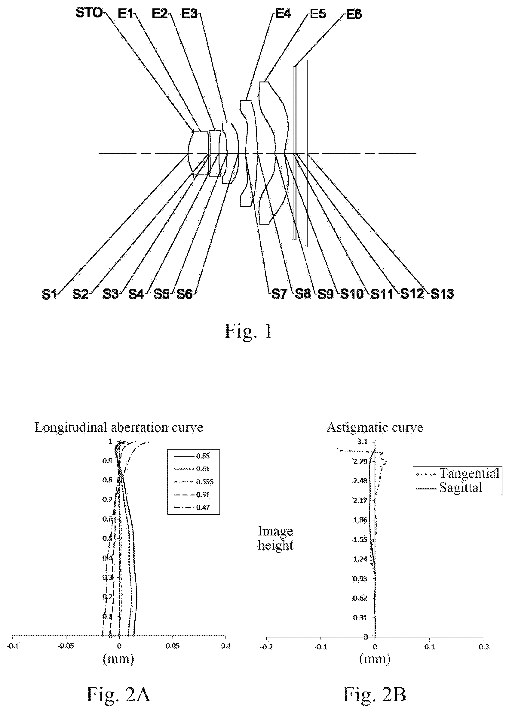
As shown in , the optical imaging lens assembly includes, sequentially along an optical axis from an object side to an image side, a diaphragm STO, a first lens E 1 , a second lens E 2 , a third lens E 3 , a fourth lens E 4 , a fifth lens E 5 , an optical filter E 6 and an image plane S 13 .
The first lens E 1 has a positive refractive power, an object-side surface S 1 of the first lens E 1 is a convex surface, and an image-side surface S 2 of the first lens E 1 is a concave surface. The second lens E 2 has a negative refractive power, an object-side surface S 3 of the second lens E 2 is a concave surface, and an image-side surface S 4 of the second lens E 2 is a concave surface. The third lens E 3 has a negative refractive power, an object-side surface S 5 of the third lens E 3 is a concave surface, and an image-side surface S 6 of the third lens E 3 is a concave surface. The fourth lens E 4 has a positive refractive power, an object-side surface S 7 of the fourth lens E 4 is a convex surface, and an image-side surface S 8 of the fourth lens E 4 is a convex surface. The fifth lens E 5 has a negative refractive power, an object-side surface S 9 of the fifth lens E 5 is a convex surface, and an image-side surface S 10 of the fifth lens E 5 is a concave surface. The optical filter E 6 has an object-side surface S 11 and an image-side surface S 12 . Light from an object sequentially passes through the surfaces S 1 -S 12 and finally forms an image on the image plane S 13 .
Table 1 is a table showing basic parameters of the optical imaging lens assembly in Example 1. Here, the units of a radius of curvature, a thickness/distance and a focal length are millimeters (mm).
TABLE 1
material
surface surface radius of thickness/ refractive abbe focal conic
number type curvature distance index number length coefficient
OBJ spherical infinite 315.0000
STO spherical infinite −0.1721
S1 aspheric 1.3410 0.6603 1.55 56.1 2.83 −0.9610
S2 aspheric 8.3193 0.0735 −64.2247
S3 aspheric −24.7758 0.2553 1.68 19.2 −8.72 −99.0000
S4 aspheric 7.7910 0.2683 −41.2256
S5 aspheric −8.2857 0.3625 1.55 56.1 −7.97 93.8655
S6 aspheric 9.2975 0.2198 21.4224
S7 aspheric 2.0534 0.3967 1.55 56.1 2.99 −4.1554
S8 aspheric −7.4400 0.5614 −20.0663
S9 aspheric 2.7793 0.3030 1.54 55.9 −2.58 −99.0000
S10 aspheric 0.8886 0.2738 −8.2873
S11 spherical infinite 0.0976 1.52 64.2
S12 spherical infinite 0.3478
S13 spherical infinite
In this example, a total effective focal length of the optical imaging lens assembly is f=3.22 mm, and a distance from the object-side surface S 1 of the first lens E 1 to the image plane S 13 on the optical axis is TTL=3.82 mm. A half of a diagonal length of an effective pixel area on the image plane S 13 is ImgH=3.01 mm. A half of a maximal field-of-view of the optical imaging lens assembly is Semi-FOV=42.1°, and a f-number of the optical imaging lens assembly is Fno=2.40.
In Example 1, the object-side surface and the image-side surface of any lens in the first to fifth lenses E 1 -E 5 are both aspheric surfaces, and the surface type x of each aspheric lens may be defined using, but not limited to, the following formula:
x = ch 2 1 + 1 - ( k + 1 ) c 2 h 2 + ∑ Aih i . ( 1 )
Here, x is the sag—the axis-component of the displacement of the surface from the aspheric vertex, when the surface is at height h from the optical axis; c is the paraxial curvature of the aspheric surface, and c=1/R (i.e., the paraxial curvature c is the reciprocal of the radius of curvature R in Table 1 above); k is the conic coefficient; and Ai is the correction coefficient of an i-th order of the aspheric surface. Table 2 below shows the high-order coefficients A 4 , A 6 , A 8 , A 10 , A 12 , A 14 , A 16 , A 18 and A 20 applicable to the aspheric surfaces S 1 -S 10 in Example 1.
TABLE 2
surface
number A4 A6 A8 A10 A12 A14 A16 A18 A20
S1 9.4697E−03 7.3276E−01 −8.7417E+00 6.3048E+01 −2.8727E+02 8.2945E+02 −1.4742E+03 1.4715E+03 −6.3202E+02
S2 −1.7180E−01 4.6423E−01 −6.6597E+00 3.6167E+01 −1.2422E+02 2.6903E+02 −3.3593E+02 2.0187E+02 −3.2062E+01
S3 −1.2062E−01 −5.6346E−01 −2.6964E−01 −4.4050E+00 3.2473E+01 −9.5075E+01 1.5379E+02 −1.3530E+02 5.1485E+01
S4 8.7773E−03 5.0275E−01 −3.7958E+00 2.3115E+01 −9.5177E+01 2.5470E+02 −4.1651E+02 3.7590E+02 −1.4264E+02
S5 −3.9843E−01 1.1200E+00 4.3889E+00 1.0909E+01 −1.7367E+01 1.5968E+01 −1.1486E+01 1.2176E+01 −7.7944E+00
S6 −7.2727E−01 1.8245E+00 −6.7073E+00 2.0173E+01 −4.4493E+01 6.6730E+01 −6.3569E+01 3.4482E+01 −8.0119E+00
S7 −3.1085E−01 5.7273E−01 −8.9318E−01 8.2858E−01 −4.7004E−01 1.1621E−01 1.4750E−02 −1.0798E−02 8.2785E−04
S8 −8.8870E−02 2.8784E−01 −3.4056E−01 2.2843E−01 −1.2463E−01 6.2519E−02 −2.2783E−02 4.6695E−03 −3.9374E−04
S9 −8.1885E−01 8.9071E−01 −5.9769E−01 2.9380E−01 −1.0350E−01 2.4708E−02 −3.7460E−03 3.2398E−04 −1.2151E−05
S10 −3.3189E−01 3.0978E−01 −1.9846E−01 8.6865E−02 −2.5564E−02 4.7945E−03 −5.2597E−04 2.8815E−05 −5.1090E−07
A illustrates a longitudinal aberration curve of the optical imaging lens assembly according to Example 1, representing deviations of focal points converged by light of different wavelengths which passes through the lens assembly. B illustrates an astigmatic curve of the optical imaging lens assembly according to Example 1, representing a curvature of a tangential image plane and a curvature of a sagittal image plane. C illustrates a distortion curve of the optical imaging lens assembly according to Example 1, representing amounts of distortion corresponding to different image heights. D illustrates a lateral color curve of the optical imaging lens assembly according to Example 1, representing deviations of different image heights on the image plane formed by light passing through the lens assembly. It can be seen from A- 2 D that the optical imaging lens assembly given in Example 1 can achieve a good imaging quality.
Example 2
An optical imaging lens assembly according to Example 2 of the present disclosure is described below with reference to D . is a schematic structural diagram of the optical imaging lens assembly according to Example 2 of the present disclosure.
As shown in , the optical imaging lens assembly includes, sequentially along an optical axis from an object side to an image side, a diaphragm STO, a first lens E 1 , a second lens E 2 , a third lens E 3 , a fourth lens E 4 , a fifth lens E 5 , an optical filter E 6 and an image plane S 13 .
The first lens E 1 has a positive refractive power, an object-side surface S 1 of the first lens E 1 is a convex surface, and an image-side surface S 2 of the first lens E 1 is a concave surface. The second lens E 2 has a negative refractive power, an object-side surface S 3 of the second lens E 2 is a concave surface, and an image-side surface S 4 of the second lens E 2 is a concave surface. The third lens E 3 has a negative refractive power, an object-side surface S 5 of the third lens E 3 is a concave surface, and an image-side surface S 6 of the third lens E 3 is a concave surface. The fourth lens E 4 has a positive refractive power, an object-side surface S 7 of the fourth lens E 4 is a convex surface, and an image-side surface S 8 of the fourth lens E 4 is a convex surface. The fifth lens E 5 has a negative refractive power, an object-side surface S 9 of the fifth lens E 5 is a convex surface, and an image-side surface S 10 of the fifth lens E 5 is a concave surface. The optical filter E 6 has an object-side surface S 11 and an image-side surface S 12 . Light from an object sequentially passes through the surfaces S 1 -S 12 and finally forms an image on the image plane S 13 .
In this example, a total effective focal length of the optical imaging lens assembly is f=3.22 mm, and a distance from the object-side surface S 1 of the first lens E 1 to the image plane S 13 on the optical axis is TTL=3.80 mm. A half of a diagonal length of an effective pixel area on the image plane S 13 is ImgH=3.01 mm. A half of a maximal field-of-view of the optical imaging lens assembly is Semi-FOV=42.1°, and a f-number of the optical imaging lens assembly is Fno=2.38.
Table 3 is a table showing basic parameters of the optical imaging lens assembly in Example 2. Here, the units of a radius of curvature, a thickness/distance and a focal length are millimeters (mm).
TABLE 3
material
surface surface radius of thickness/ refractive abbe focal conic
number type curvature distance index number length coefficient
OBJ spherical infinite 315.0000
STO spherical infinite −0.1784
S1 aspheric 1.3073 0.5736 1.55 56.1 2.58 −0.9700
S2 aspheric 15.0822 0.0385 41.4839
S3 aspheric −2147.43 0.2293 1.68 19.2 −6.33 −99.0000
S4 aspheric 4.2968 0.2803 −10.3321
S5 aspheric −12.4086 0.3627 1.55 56.1 −10.35 99.0000
S6 aspheric 10.4750 0.2704 94.1903
S7 aspheric 3.5329 0.4100 1.55 56.1 3.20 −1.2704
S8 aspheric −3.3187 0.6190 −3.5014
S9 aspheric 2.6573 0.3030 1.54 55.9 −2.53 −99.0000
S10 aspheric 0.8624 0.2711 −8.3722
S11 spherical infinite 0.0976 1.52 64.2
S12 spherical infinite 0.3395
S13 spherical infinite
In Example 2, the object-side surface and the image-side surface of any lens in the first to fifth lenses E 1 -E 5 are both aspheric surfaces. Table 4 below shows the high-order coefficients A 4 , A 6 , A 8 , A 10 , A 12 , A 14 , A 16 , A 18 and A 20 applicable to the aspheric surfaces S 1 -S 10 in Example 2.
TABLE 4
surface
number A4 A6 A8 A10 A12 A14 A16 A18 A20
S1 2.1647E−02 5.4234E−01 −6.3357E+00 4.4949E+01 −2.0314E+02 5.8390E+02 −1.0371E+03 1.0371E+03 −4.4724E+02
S2 −2.6818E−01 7.9846E−01 −5.7387E+00 4.3086E+01 −2.3568E+02 7.5895E+02 −1.3827E+03 1.3202E+03 −5.1039E+02
S3 −1.7545E−01 1.5771E−01 4.7934E+00 −3.3075E+01 9.2086E+01 −1.0166E+02 −3.5672E+01 1.7677E+02 −1.1008E+02
S4 −3.1701E−02 1.0436E+00 −8.4007E+00 6.0362E+01 −2.8730E+02 8.4592E+02 −1.4856E+03 1.4299E+03 −5.8073E+02
S5 −5.2201E−01 1.8271E+00 −1.3684E+01 7.7276E+01 −3.1282E+02 8.4351E+02 −1.4312E+03 1.3708E+03 −5.6120E+02
S6 −6.4790E−01 1.8419E+00 −8.4782E+00 2.9029E+01 −6.9599E+01 1.1121E+02 −1.1198E+02 6.4004E+01 −1.5628E+01
S7 −3.1412E−01 7.2254E−01 −1.8192E+00 3.2320E+00 −4.1000E+00 3.5487E+00 −1.9883E+00 6.4676E−01 −9.1402E−02
S8 −1.6224E−01 4.8712E−01 −8.5761E−01 1.1049E+00 −9.7726E−01 5.5710E−01 −1.9382E−01 3.7326E−02 −3.0449E−03
S9 −8.3536E−01 9.2793E−01 −6.5186E−01 3.3224E−01 −1.1889E−01 2.8446E−02 −4.2995E−03 3.7035E−04 −1.3854E−05
S10 −3.1788E−01 2.8460E−01 −1.7305E−01 7.1562E−02 −1.9986E−02 3.5972E−03 −3.8765E−04 2.2127E−05 −4.9839E−07
A illustrates a longitudinal aberration curve of the optical imaging lens assembly according to Example 2, representing deviations of focal points converged by light of different wavelengths which passes through the lens assembly. B illustrates an astigmatic curve of the optical imaging lens assembly according to Example 2, representing a curvature of a tangential image plane and a curvature of a sagittal image plane. C illustrates a distortion curve of the optical imaging lens assembly according to Example 2, representing amounts of distortion corresponding to different image heights. D illustrates a lateral color curve of the optical imaging lens assembly according to Example 2, representing deviations of different image heights on the image plane formed by light passing through the lens assembly. It can be seen from A- 4 D that the optical imaging lens assembly given in Example 2 can achieve a good imaging quality.
Example 3
An optical imaging lens assembly according to Example 3 of the present disclosure is described below with reference to D . is a schematic structural diagram of the optical imaging lens assembly according to Example 3 of the present disclosure.
As shown in , the optical imaging lens assembly includes, sequentially along an optical axis from an object side to an image side, a diaphragm STO, a first lens E 1 , a second lens E 2 , a third lens E 3 , a fourth lens E 4 , a fifth lens E 5 , an optical filter E 6 and an image plane S 13 .
The first lens E 1 has a positive refractive power, an object-side surface S 1 of the first lens E 1 is a convex surface, and an image-side surface S 2 of the first lens E 1 is a concave surface. The second lens E 2 has a negative refractive power, an object-side surface S 3 of the second lens E 2 is a convex surface, and an image-side surface S 4 of the second lens E 2 is a concave surface. The third lens E 3 has a negative refractive power, an object-side surface S 5 of the third lens E 3 is a concave surface, and an image-side surface S 6 of the third lens E 3 is a concave surface. The fourth lens E 4 has a positive refractive power, an object-side surface S 7 of the fourth lens E 4 is a convex surface, and an image-side surface S 8 of the fourth lens E 4 is a convex surface. The fifth lens E 5 has a negative refractive power, an object-side surface S 9 of the fifth lens E 5 is a convex surface, and an image-side surface S 10 of the fifth lens E 5 is a concave surface. The optical filter E 6 has an object-side surface S 11 and an image-side surface S 12 . Light from an object sequentially passes through the surfaces S 1 -S 12 and finally forms an image on the image plane S 13 .
In this example, a total effective focal length of the optical imaging lens assembly is f=3.22 mm, and a distance from the object-side surface S 1 of the first lens E 1 to the image plane S 13 on the optical axis is TTL=3.78 mm. A half of a diagonal length of an effective pixel area on the image plane S 13 is ImgH=3.02 mm. A half of a maximal field-of-view of the optical imaging lens assembly is Semi-FOV=42.1°, and a f-number of the optical imaging lens assembly is Fno=2.38.
Table 5 is a table showing basic parameters of the optical imaging lens assembly in Example 3. Here, the units of a radius of curvature, a thickness/distance and a focal length are millimeters (mm).
TABLE 5
material
surface surface radius of thickness/ refractive abbe focal conic
number type curvature distance index number length coefficient
OBJ spherical infinite 310.0000
STO spherical infinite −0.1831
S1 aspheric 1.2837 0.5676 1.55 56.1 2.48 −0.9468
S2 aspheric 21.3308 0.0181 −99.0000
S3 aspheric 62.5783 0.2200 1.68 19.2 −6.11 99.0000
S4 aspheric 3.8783 0.2777 −6.8025
S5 aspheric −10.1766 0.3753 1.55 56.1 −10.75 61.5041
S6 aspheric 14.0558 0.2802 99.0000
S7 aspheric 6.8824 0.4150 1.55 56.1 3.28 11.1084
S8 aspheric −2.3690 0.6442 −0.9917
S9 aspheric 2.5765 0.3000 1.54 55.9 −2.32 −99.0000
S10 aspheric 0.8064 0.2618 −8.6287
S11 spherical infinite 0.0976 1.52 64.2
S12 spherical infinite 0.3176
S13 spherical infinite
In Example 3, the object-side surface and the image-side surface of any lens in the first to fifth lenses E 1 -E 5 are both aspheric surfaces. Table 6 below shows the high-order coefficients A 4 , A 6 , A 8 , A 10 , A 12 , A 14 , A 16 , A 18 and A 20 applicable to the aspheric surfaces S 1 -S 10 in Example 3.
TABLE 6
surface
number A4 A6 A8 A10 A12 A14 A16 A18 A20
S1 2.8953E−02 4.1887E−01 −4.7471E+00 3.2965E+01 −1.4716E+02 4.1993E+02 −7.4435E+02 7.4578E+02 −3.2366E+02
S2 −4.6434E−01 1.4510E+00 6.6284E−01 −1.7671E+01 1.0160E+01 1.6579E+02 −4.7682E+02 4.9170E+02 −1.6257E+02
S3 −3.3734E−01 7.3914E−01 1.0836E+01 −9.2062E+01 3.3863E+02 −7.1106E+02 9.0261E+02 −6.7135E+02 2.3567E+02
S4 −4.1042E−02 1.2679E+00 −1.0723E+01 7.9111E+01 −3.8805E+02 1.1828E+03 −2.1565E+03 2.1626E+03 −9.2025E+02
S5 −5.0380E−01 2.1955E+00 −2.0937E+01 1.4055E+02 −6.4065E+02 1.8893E+03 −3.4446E+03 3.5158E+03 −1.5289E+03
S6 −5.7019E−01 1.7648E+00 −8.4402E+00 2.9794E+01 −7.3674E+01 1.2140E+02 −1.2621E+02 7.4801E+01 −1.9060E+01
S7 −4.1275E−01 9.6118E−01 −2.9010E+00 6.7433E+00 −1.0700E+01 1.1045E+01 −7.1519E+00 2.6402E+00 −4.2078E−01
S8 −2.9825E−01 7.9548E−01 −1.8338E+00 3.2714E+00 −3.6277E+00 2.4372E+00 −9.7550E−01 2.1505E−01 −2.0160E−02
S9 −1.0894E+00 1.4861E+00 −1.1775E+00 6.1375E−01 −2.1364E−01 4.9078E−02 −7.1452E−03 5.9789E−04 −2.1925E−05
S10 −4.1651E−01 4.5041E−01 −2.9723E−01 1.2900E−01 −3.7829E−02 7.3722E−03 −9.1073E−04 6.4552E−05 −2.0050E−06
A illustrates a longitudinal aberration curve of the optical imaging lens assembly according to Example 3, representing deviations of focal points converged by light of different wavelengths which passes through the lens assembly. B illustrates an astigmatic curve of the optical imaging lens assembly according to Example 3, representing a curvature of a tangential image plane and a curvature of a sagittal image plane. C illustrates a distortion curve of the optical imaging lens assembly according to Example 3, representing amounts of distortion corresponding to different image heights. D illustrates a lateral color curve of the optical imaging lens assembly according to Example 3, representing deviations of different image heights on the image plane formed by light passing through the lens assembly. It can be seen from A- 6 D that the optical imaging lens assembly given in Example 3 can achieve a good imaging quality.
Example 4
An optical imaging lens assembly according to Example 4 of the present disclosure is described below with reference to D . is a schematic structural diagram of the optical imaging lens assembly according to Example 4 of the present disclosure.
As shown in , the optical imaging lens assembly includes, sequentially along an optical axis from an object side to an image side, a diaphragm STO, a first lens E 1 , a second lens E 2 , a third lens E 3 , a fourth lens E 4 , a fifth lens E 5 , an optical filter E 6 and an image plane S 13 .
The first lens E 1 has a positive refractive power, an object-side surface S 1 of the first lens E 1 is a convex surface, and an image-side surface S 2 of the first lens E 1 is a concave surface. The second lens E 2 has a negative refractive power, an object-side surface S 3 of the second lens E 2 is a convex surface, and an image-side surface S 4 of the second lens E 2 is a concave surface. The third lens E 3 has a negative refractive power, an object-side surface S 5 of the third lens E 3 is a concave surface, and an image-side surface S 6 of the third lens E 3 is a convex surface. The fourth lens E 4 has a positive refractive power, an object-side surface S 7 of the fourth lens E 4 is a convex surface, and an image-side surface S 8 of the fourth lens E 4 is a convex surface. The fifth lens E 5 has a negative refractive power, an object-side surface S 9 of the fifth lens E 5 is a convex surface, and an image-side surface S 10 of the fifth lens E 5 is a concave surface. The optical filter E 6 has an object-side surface S 11 and an image-side surface S 12 . Light from an object sequentially passes through the surfaces S 1 -S 12 and finally forms an image on the image plane S 13 .
In this example, a total effective focal length of the optical imaging lens assembly is f=3.12 mm, and a distance from the object-side surface S 1 of the first lens E 1 to the image plane S 13 on the optical axis is TTL=3.75 mm. A half of a diagonal length of an effective pixel area on the image plane S 13 is ImgH=3.01 mm. A half of a maximal field-of-view of the optical imaging lens assembly is Semi-FOV=43.0°, and a f-number of the optical imaging lens assembly is Fno=2.37.
Table 7 is a table showing basic parameters of the optical imaging lens assembly in Example 4. Here, the units of a radius of curvature, a thickness/distance and a focal length are millimeters (mm).
TABLE 7
material
surface surface radius of thickness/ refractive abbe focal conic
number type curvature distance index number length coefficient
OBJ spherical infinite 308.0000
STO spherical infinite −0.1747
S1 aspheric 1.2800 0.5307 1.55 56.1 2.55 −0.8883
S2 aspheric 13.3894 0.0253 95.7395
S3 aspheric 19.4665 0.2200 1.68 19.2 −5.89 −99.0000
S4 aspheric 3.2966 0.2627 −7.3175
S5 aspheric −12.7982 0.3846 1.55 56.1 −23.85 36.2430
S6 aspheric −762.7494 0.3226 −99.0000
S7 aspheric 10.8005 0.4124 1.55 56.1 3.37 23.0989
S8 aspheric −2.1846 0.6152 −1.3833
S9 aspheric 2.4383 0.3000 1.54 55.9 −2.35 −92.8461
S10 aspheric 0.7954 0.2584 −8.0302
S11 spherical infinite 0.0976 1.52 64.2
S12 spherical infinite 0.3157
S13 spherical infinite
In Example 4, the object-side surface and the image-side surface of any lens in the first to fifth lenses E 1 -E 5 are both aspheric surfaces. Table 8 below shows the high-order coefficients A 4 , A 6 , A 8 , A 10 , A 12 , A 14 , A 16 , A 18 and A 20 applicable to the aspheric surfaces S 1 -S 10 in Example 4.
TABLE 8
surface
number A4 A6 A8 A10 A12 A14 A16 A18 A20
S1 2.9009E−02 4.9258E−01 −6.0132E+00 4.5291E+01 −2.1738E+02 6.6508E+02 −1.2601E+03 1.3459E+03 −6.2047E+02
S2 −4.0109E−01 1.7526E+00 −9.4089E+00 7.2960E+01 −4.5813E+02 1.7131E+03 −3.6899E+03 4.2711E+03 −2.0637E+03
S3 −3.1577E−01 1.1843E+00 7.6551E−01 −9.6663E+00 −5.2798E+01 4.8456E+02 −1.4343E+03 1.9745E+03 −1.0683E+03
S4 −4.2621E−02 1.0367E+00 −6.3668E+00 4.1409E+01 −2.0025E+02 6.2311E+02 −1.1745E+03 1.2247E+03 −5.4205E+02
S5 −4.3408E−01 1.3899E+00 −1.1275E+01 6.5471E+01 −2.7446E+02 7.7361E+02 −1.3825E+03 1.3986E+03 −6.0461E+02
S6 −4.6290E−01 1.3428E+00 −6.7644E+00 2.4507E+01 −6.1365E+01 1.0095E+02 −1.0334E+02 5.9365E+01 −1.4373E+01
S7 −3.4195E−01 7.9685E−01 −2.4182E+00 5.3881E+00 −8.0085E+00 7.6874E+00 −4.6103E+00 1.5714E+00 −2.3074E−01
S8 −2.6900E−01 7.2362E−01 −1.6372E+00 2.7537E+00 −2.8463E+00 1.7796E+00 −6.6258E−01 1.3572E−01 −1.1793E−02
S9 −9.4066E−01 1.1699E+00 −8.3758E−01 3.9398E−01 −1.2373E−01 2.5622E−02 −3.3573E−03 2.5228E−04 −8.2858E−06
S10 −3.3175E−01 3.2018E−01 −1.9118E−01 7.4727E−02 −1.9472E−02 3.2891E−03 −3.3937E−04 1.9121E−05 −4.4224E−07
A illustrates a longitudinal aberration curve of the optical imaging lens assembly according to Example 4, representing deviations of focal points converged by light of different wavelengths which passes through the lens assembly. B illustrates an astigmatic curve of the optical imaging lens assembly according to Example 4, representing a curvature of a tangential image plane and a curvature of a sagittal image plane. C illustrates a distortion curve of the optical imaging lens assembly according to Example 4, representing amounts of distortion corresponding to different image heights. D illustrates a lateral color curve of the optical imaging lens assembly according to Example 4, representing deviations of different image heights on the image plane formed by light passing through the lens assembly. It can be seen from A- 8 D that the optical imaging lens assembly given in Example 4 can achieve a good imaging quality.
Example 5
An optical imaging lens assembly according to Example 5 of the present disclosure is described below with reference to D . is a schematic structural diagram of the optical imaging lens assembly according to Example 5 of the present disclosure.
As shown in , the optical imaging lens assembly includes, sequentially along an optical axis from an object side to an image side, a diaphragm STO, a first lens E 1 , a second lens E 2 , a third lens E 3 , a fourth lens E 4 , a fifth lens E 5 , an optical filter E 6 and an image plane S 13 .
The first lens E 1 has a positive refractive power, an object-side surface S 1 of the first lens E 1 is a convex surface, and an image-side surface S 2 of the first lens E 1 is a concave surface. The second lens E 2 has a negative refractive power, an object-side surface S 3 of the second lens E 2 is a convex surface, and an image-side surface S 4 of the second lens E 2 is a concave surface. The third lens E 3 has a positive refractive power, an object-side surface S 5 of the third lens E 3 is a convex surface, and an image-side surface S 6 of the third lens E 3 is a convex surface. The fourth lens E 4 has a positive refractive power, an object-side surface S 7 of the fourth lens E 4 is a convex surface, and an image-side surface S 8 of the fourth lens E 4 is a convex surface. The fifth lens E 5 has a negative refractive power, an object-side surface S 9 of the fifth lens E 5 is a convex surface, and an image-side surface S 10 of the fifth lens E 5 is a concave surface. The optical filter E 6 has an object-side surface S 11 and an image-side surface S 12 . Light from an object sequentially passes through the surfaces S 1 -S 12 and finally forms an image on the image plane S 13 .
In this example, a total effective focal length of the optical imaging lens assembly is f=3.15 mm, and a distance from the object-side surface S 1 of the first lens E 1 to the image plane S 13 on the optical axis is TTL=3.91 mm. A half of a diagonal length of an effective pixel area on the image plane S 13 is ImgH=3.01 mm. A half of a maximal field-of-view of the optical imaging lens assembly is Semi-FOV=42.7°, and a f-number of the optical imaging lens assembly is Fno=2.15.
Table 9 is a table showing basic parameters of the optical imaging lens assembly in Example 5. Here, the units of a radius of curvature, a thickness/distance and a focal length are millimeters (mm).
TABLE 9
material
surface surface radius of thickness/ refractive abbe focal conic
number type curvature distance index number length coefficient
OBJ spherical infinite 350.0000
STO spherical infinite −0.2381
S1 aspheric 1.2829 0.4383 1.55 56.1 3.05 −0.4767
S2 aspheric 4.8930 0.1294 36.5374
S3 aspheric 15.9160 0.2550 1.68 19.2 −6.69 99.0000
S4 aspheric 3.5045 0.2113 −10.0676
S5 aspheric 42.0215 0.4800 1.55 56.1 10.13 85.3733
S6 aspheric −6.3410 0.3915 −99.0000
S7 aspheric 13.6354 0.4704 1.55 56.1 4.46 −57.6737
S8 aspheric −2.9282 0.4845 −2.0526
S9 aspheric 7.9932 0.3921 1.54 55.9 −2.30 5.8534
S10 aspheric 1.0517 0.2702 −6.8663
S11 spherical infinite 0.2100 1.52 64.2
S12 spherical infinite 0.1724
S13 spherical infinite
In Example 5, the object-side surface and the image-side surface of any lens in the first to fifth lenses E 1 -E 5 are both aspheric surfaces. Table 10 below shows the high-order coefficients A 4 , A 6 , A 8 , A 10 , A 12 , A 14 , A 16 , A 18 and A 20 applicable to the aspheric surfaces S 1 -S 10 in Example 5.
TABLE 10
surface
number A4 A6 A8 A10 A12 A14 A16 A18 A20
S1 3.3815E−02 2.2364E−01 −1.8549E+00 1.1814E+01 −4.6335E+01 1.1529E+02 −1.7596E+02 1.5073E+02 −5.5415E+01
S2 7.8575E−02 −1.1907E−02 9.0859E−01 −8.0322E+00 3.9717E+01 −1.2132E+02 2.2225E+02 −2.2422E+02 9.4093E+01
S3 −1.2754E−01 1.5232E−01 8.8177E−01 −9.9441E+00 5.4714E+01 −1.8164E+02 3.5595E+02 −3.7921E+02 1.6761E+02
S4 −5.9160E−02 7.9434E−01 −7.0795E+00 5.2202E+01 −2.3916E+02 6.7848E+02 −1.1585E−03 1.0911E−03 −4.3533E−02
S5 −1.9371E−01 2.8739E−01 −2.0923E+00 1.0526E+01 −3.5769E+01 7.9733E+01 −1.1116E+02 8.9847E+01 −3.2074E+01
S6 −2.2971E−01 2.8623E−01 −1.6359E+00 6.2517E+00 −1.5748E+01 2.5455E+01 −2.5274E+01 1.4074E+01 −3.3339E+00
S7 −6.5981E−02 −9.3691E−03 5.8598E−02 −1.7880E−01 2.5688E−01 −2.2906E−01 1.2442E−01 −3.5712E−02 4.0742E−03
S8 −4.7595E−02 8.0454E−02 −4.9129E−02 4.7637E−02 −4.4922E−02 2.5925E−02 −8.7242E−03 1.5995E−03 −1.2375E−04
S9 −7.2129E−01 7.4691E−01 −5.1942E−01 2.7754E−01 −1.0639E−01 2.7258E−02 4.3873E−03 4.0051E−04 −1.5827E−05
S10 −2.1949E−01 1.8527E−01 −1.0170E−01 3.6325E−02 −8.2571E−03 1.1014E−03 −7.1374E−05 7.1768E−07 9.3501E−08
A illustrates a longitudinal aberration curve of the optical imaging lens assembly according to Example 5, representing deviations of focal points converged by light of different wavelengths which passes through the lens assembly. B illustrates an astigmatic curve of the optical imaging lens assembly according to Example 5, representing a curvature of a tangential image plane and a curvature of a sagittal image plane. C illustrates a distortion curve of the optical imaging lens assembly according to Example 5, representing amounts of distortion corresponding to different image heights. D illustrates a lateral color curve of the optical imaging lens assembly according to Example 5, representing deviations of different image heights on the image plane formed by light passing through the lens assembly. It can be seen from A- 10 D that the optical imaging lens assembly given in Example 5 can achieve a good imaging quality.
Example 6
An optical imaging lens assembly according to Example 6 of the present disclosure is described below with reference to D . is a schematic structural diagram of the optical imaging lens assembly according to Example 6 of the present disclosure.
As shown in , the optical imaging lens assembly includes, sequentially along an optical axis from an object side to an image side, a diaphragm STO, a first lens E 1 , a second lens E 2 , a third lens E 3 , a fourth lens E 4 , a fifth lens E 5 , an optical filter E 6 and an image plane S 13 .
The first lens E 1 has a positive refractive power, an object-side surface S 1 of the first lens E 1 is a convex surface, and an image-side surface S 2 of the first lens E 1 is a concave surface. The second lens E 2 has a negative refractive power, an object-side surface S 3 of the second lens E 2 is a convex surface, and an image-side surface S 4 of the second lens E 2 is a concave surface. The third lens E 3 has a positive refractive power, an object-side surface S 5 of the third lens E 3 is a convex surface, and an image-side surface S 6 of the third lens E 3 is a convex surface. The fourth lens E 4 has a positive refractive power, an object-side surface S 7 of the fourth lens E 4 is a convex surface, and an image-side surface S 8 of the fourth lens E 4 is a convex surface. The fifth lens E 5 has a negative refractive power, an object-side surface S 9 of the fifth lens E 5 is a convex surface, and an image-side surface S 10 of the fifth lens E 5 is a concave surface. The optical filter E 6 has an object-side surface S 11 and an image-side surface S 12 . Light from an object sequentially passes through the surfaces S 1 -S 12 and finally forms an image on the image plane S 13 .
In this example, a total effective focal length of the optical imaging lens assembly is f=3.10 mm, and a distance from the object-side surface S 1 of the first lens E 1 to the image plane S 13 on the optical axis is TTL=3.86 mm. A half of a diagonal length of an effective pixel area on the image plane S 13 is ImgH=3.01 mm. Half of a maximal field-of-view of the optical imaging lens assembly is Semi-FOV=43.2°, and a f-number of the optical imaging lens assembly is Fno=2.15.
Table 11 is a table showing basic parameters of the optical imaging lens assembly in Example 6. Here, the units of a radius of curvature, a thickness/distance and a focal length are millimeters (mm).
TABLE 11
material
surface surface radius of thickness/ refractive abbe focal conic
number type curvature distance index number length coefficient
OBJ spherical infinite 350.0000
STO spherical infinite −0.2356
S1 aspheric 1.2654 0.4341 1.55 56.1 3.07 −0.4344
S2 aspheric 4.5271 0.1378 34.0680
S3 aspheric 16.8039 0.2550 1.68 19.2 −6.72 −9.9555
S4 aspheric 3.5604 0.1891 −11.6289
S5 aspheric 16.0784 0.4800 1.55 56.1 8.71 6.5347
S6 aspheric −6.6775 0.3876 −96.0978
S7 aspheric 28.8217 0.4779 1.55 56.1 4.31 −99.0000
S8 aspheric −2.5503 0.4367 −1.2780
S9 aspheric 11.6875 0.4087 1.54 55.9 −2.18 13.8431
S10 aspheric 1.0523 0.2704 −7.2404
S11 spherical infinite 0.2100 1.52 64.2
S12 spherical infinite 0.1677
S13 spherical infinite
In Example 6, the object-side surface and the image-side surface of any lens in the first to fifth lenses E 1 -E 5 are both aspheric surfaces. Table 12 below shows the high-order coefficients A 4 , A 6 , A 8 , A 10 , A 12 , A 14 , A 16 , A 18 and A 20 applicable to the aspheric surfaces S 1 -S 10 in Example 6.
TABLE 12
surface
number A4 A6 A8 A10 A12 A14 A16 A18 A20
S1 3.3280E−02 2.7328E−01 −2.4994E+00 1.6967E+01 −7.0417E+01 1.8401E+02 −2.9339E+02 2.6131E+02 −9.9502E+01
S2 −7.7932E−02 1.1590E−01 −1.1247E+00 8.3637E+00 −4.2738E+01 1.3923E+02 −2.8278E+02 3.2387E+02 −1.6211E+02
S3 −1.2427E−01 1.6500E−01 4.9044E−01 −7.9505E+00 4.9373E+01 −1.7756E+02 3.6939E+02 −4.1375E+02 1.9106E+02
S4 −5.3048E−02 6.2991E−01 4.8811E+00 3.4492E+01 −1.5404E+02 4.2849E+02 −7.1860E+02 6.6497E+02 −2.6066E+02
S5 −1.7385E−01 2.9312E−01 −2.1601E+00 1.1207E+01 −3.8428E+01 8.5160E+01 −1.1667E+02 9.1601E+01 −3.1691E+01
S6 −2.0201E−01 2.6077E−01 −1.5774E+00 6.0803E+00 −1.5383E+01 2.4996E+01 −2.4991E+01 1.4052E+01 −3.3704E+00
S7 −7.2880E−02 −7.9722E−03 3.4847E−02 −1.5380E−01 2.7781E−01 −3.0259E−01 1.9212E−01 −6.2178E−02 7.8517E−03
S8 −6.5844E−02 1.0466E−01 −9.0231E−02 8.8002E−02 −5.7601E−02 2.2536E−02 −5.4802E−03 8.1854E−04 −5.9198E−05
S9 −7.5528E−01 8.2448E−01 −6.2502E−01 3.6635E−01 −1.5099E−01 4.0782E−02 −6.8285E−03 6.4298E−04 −2.6060E−05
S10 −2.1661E−01 1.8545E−01 −1.0420E−01 3.8340E−02 −9.1521E−03 1.3499E−03 −1.1448E−04 4.9461E−06 −8.2308E−08
A illustrates a longitudinal aberration curve of the optical imaging lens assembly according to Example 6, representing deviations of focal points converged by light of different wavelengths which passes through the lens assembly. B illustrates an astigmatic curve of the optical imaging lens assembly according to Example 6, representing a curvature of a tangential image plane and a curvature of a sagittal image plane. C illustrates a distortion curve of the optical imaging lens assembly according to Example 6, representing amounts of distortion corresponding to different image heights. D illustrates a lateral color curve of the optical imaging lens assembly according to Example 6, representing deviations of different image heights on the image plane formed by light passing through the lens assembly. It can be seen from A- 12 D that the optical imaging lens assembly given in Example 6 can achieve a good imaging quality.
In summary, Example 1-6 respectively satisfy the relationships shown in Table 13.
TABLE 13
conditional expression/example 1 2 3 4 5 6
TTL/ImgH 1.27 1.26 1.25 1.24 1.30 1.28
CT4/T34 1.80 1.52 1.48 1.28 1.20 1.23
R1/f1 0.47 0.51 0.52 0.50 0.42 0.41
f12/f123 0.69 0.75 0.77 0.88 1.32 1.38
|f/f4| + |f/f5| 2.33 2.28 2.37 2.26 2.07 2.14
(R9 + R10)/(R9 − R10) 1.94 1.96 1.91 1.97 1.30 1.20
SAG41/SAG51 0.31 0.32 0.39 0.46 0.38 0.42
EPD/ΣCT 0.68 0.72 0.72 0.71 0.72 0.70
DT11/DT12 0.97 0.98 0.99 0.99 1.04 1.05
tan(Semi − FoV)/CT5 2.98 2.98 3.01 3.10 2.36 2.29
ΣAT/TD 0.33 0.36 0.36 0.37 0.35 0.33
(CT2 + CT3)/(T12 + T23) 1.81 1.86 2.01 2.10 2.16 2.25
The foregoing is only a description of the preferred examples of the present disclosure and the applied technical principles. It should be appreciated by those skilled in the art that the inventive scope of the present disclosure is not limited to the technical solution formed by the particular combinations of the above technical features. The inventive scope should also cover other technical solutions formed by any combination of the above technical features or equivalent features thereof without departing from the concept of the invention, such as, technical solutions formed by replacing the features as disclosed in the present disclosure with (but not limited to) technical features with similar functions.
Figures (9)
Citations
This patent cites (20)
- US2013/0271642
- US2014/0111874
- US2017/0139187
- US2017/0235109
- US2018/0113281
- US2018/0231742
- US103592743
- US203773141
- US104395806
- US107167900
- US107290843
- US206684372
- US109298516
- US208984870
- US209265059
- US110488467
- US211086749
- US114236751
- US2013174741
- US2015084066