Zoom Lens and Image Capturing Apparatus Including the Same
Abstract
A zoom lens B 0 includes a first lens unit B 1 having negative refractive, a second lens unit B 2 having positive refractive power, and a third lens unit B 3 having negative refractive power in order from an object side to an image side. The first lens unit B 1 moves during zooming. The first lens unit B 1 includes a negative lens G 1 disposed closest to the object side and at least one positive lens. Lenses included in the second lens unit B 2 all have positive refractive power. The number of lenses included in the third lens unit B 3 is two or less. The third lens unit B 3 moves toward the image side during focusing from infinity to close range.
Claims (24)
1. A zoom lens comprising: a first lens unit having negative refractive power, a second lens unit having positive refractive power and lenses included in the second lens unit are all positive single lenses, and a third lens unit having negative refractive power in order from an object side to an image side, wherein a distance between the first lens unit and the second lens unit and a distance between the second lens unit and the third lens unit change during at least one of zooming and focusing, wherein the first lens unit moves during zooming, wherein the first lens unit includes a negative lens G 1 disposed closest to the object side and at least one positive lens, wherein the second lens unit consists of an aperture stop, a first positive lens, a second positive lens, and lenses included in the second lens unit are all positive single lenses, wherein a number of lenses included in the third lens unit is two or less, wherein the third lens unit moves toward the image side during focusing from infinity to close range, and wherein the following inequalities are satisfied: 1.40< Nd _ G 1<1.80 18< vd _ B 3 n≤ 24.8 where Nd_G 1 is a refractive index of the negative lens G 1 , and vd_B 3 n is an Abbe number of a negative lens having strongest refractive power among negative lenses included in the third lens unit.
18. An image capturing apparatus comprising: a zoom lens; and an image sensor configured to capture an optical image formed by the zoom lens, wherein the zoom lens comprises: a first lens unit having negative refractive power, a second lens unit having positive refractive power, and a third lens unit having negative refractive power in order from an object side to an image side, wherein a distance between the first lens unit and the second lens unit and a distance between the second lens unit and the third lens unit change during at least one of zooming and focusing, wherein the first lens unit moves during zooming, wherein the first lens unit includes a negative lens G 1 disposed closest to the object side and at least one positive lens, wherein the second lens unit consists of an aperture stop, a first positive lens, a second positive lens, and lenses included in the second lens unit are all positive single lenses, wherein a number of lenses included in the third lens unit is two or less, wherein the third lens unit moves toward the image side during focusing from infinity to close range, and wherein the following inequalities are satisfied: 1.40< Nd _ G 1<1.80 18< vd _ B 3 n≤ 24.8
Show 22 dependent claims
2. The zoom lens according to claim 1 , wherein the following inequality is satisfied: −5.0< SF B 3 n< 0.50 where SF_B 3 n is a shape factor of a negative lens having strongest negative refractive power among the third lens unit.
3. The zoom lens according to claim 1 , wherein the following inequality is satisfied: 1.0<| f 1|/ fw< 3.0 where fw is a focal length at a wide angle end of the zoom lens, and f1 is a focal length of the first lens unit.
4. The zoom lens according to claim 1 , wherein the following inequality is satisfied: 0.2< f 2/ fw< 5.0 where f2 is a focal length of the second lens unit, and fw is a focal length at a wide angle end of the zoom lens.
5. The zoom lens according to claim 1 , wherein the following inequality is satisfied: 0.1< f 3/ f 1<5.0 where f3 is a focal length of the third lens unit, and f1 is a focal length of the first lens unit.
6. The zoom lens according to claim 1 , wherein a number of lenses included from a lens disposed closest to the object side in the second lens unit to a lens closest to the image side in the zoom lens is five or less.
7. The zoom lens according to claim 1 , wherein the third lens unit consists of a single lens having negative refractive power.
8. The zoom lens according to claim 1 , wherein the first lens unit includes an aspherical lens.
9. The zoom lens according to claim 8 , wherein the aspherical lens is a resin lens.
10. The zoom lens according to claim 1 , wherein at least a part of the second lens unit moves in a direction including a component perpendicular to an optical axis in image blurring correction.
11. The zoom lens according to claim 1 , further comprising a fourth lens unit having positive refractive power disposed adjacent to an image side of the third lens group, wherein during zooming, the second lens unit and the fourth lens unit integrally moves, and a distance between the third lens unit and the fourth lens unit changes.
12. The zoom lens according to claim 11 , wherein the third lens unit consists of one biconcave lens.
13. The zoom lens according to claim 11 , wherein the fourth lens unit consists of one lens.
14. The zoom lens according to claim 1 , wherein the second lens unit consists of the first positive lens, the aperture stop and the second positive lens, arranged in order from the object side to the image side.
15. The zoom lens according to claim 14 , wherein the first positive lens is arranged with a convex surface facing the image side, and the second positive lens is arranged with a convex surface facing the object side.
16. The zoom lens according to claim 1 , wherein the second lens unit consists of the aperture stop, the first positive lens and the second positive lens, arranged in order from the object side to the image side.
17. The zoom lens according to claim 16 , wherein the first positive lens is arranged with a convex surface facing the image side, and the second positive lens is arranged with a convex surface facing the object side.
19. The image capturing apparatus according to claim 18 , wherein, in the zoom lens, the following inequality is satisfied: −5.0< SF _ B 3 n< 0.50 where SF_B 3 n is a shape factor of a negative lens having strongest refractive power among negative lenses included in the third lens unit.
20. The image capturing apparatus according to claim 18 , wherein, in the zoom lens, the following inequality is satisfied: 1.0<| f 1|/ fw< 3.0 where fw is a focal length at a wide angle end of the zoom lens, and f1 is a focal length of the first lens unit.
21. The image capturing apparatus according to claim 18 , wherein, in the zoom lens, the following inequality is satisfied: 0.2< f 2/ fw< 5.0 where f2 is a focal length of the second lens unit, and fw is a focal length at a wide angle end of the zoom lens.
22. The image capturing apparatus according to claim 18 , wherein, in the zoom lens, the following inequality is satisfied: 0.1< f 3/ f 1<5.0 where f3 is a focal length of the third lens unit, and f1 is a focal length of the first lens unit.
23. The image capturing apparatus according to claim 18 , wherein, in the zoom lens, a number of lenses included from a lens disposed closest to the object side in the second lens unit to a lens closest to the image side in the zoom lens is five or less.
24. The image capturing apparatus according to claim 18 , wherein the zoom lens further comprises a fourth lens unit having positive refractive power disposed adjacent to an image side of the third lens group, and during zooming, the second lens unit and the fourth lens unit integrally moves, and a distance between the third lens unit and the fourth lens unit changes.
Full Description
Show full text →
BACKGROUND OF THE INVENTION
Field of the Invention
The aspect of the embodiments relates to a zoom lens suitable for image capturing apparatus, such as a digital video camera, a digital still camera, a camera for broadcast, a camera for silver-halide film, and a monitoring camera.
Description of the Related Art
As a zoom lens that is used for an image capturing apparatus, a negative-lead zoom lens in which a lens unit having negative refractive power is disposed at a position closest to the object has been known.
Japanese Patent Laid-Open No. 2014-178388 discusses a negative-lead zoom lens including a first lens unit having negative refractive power, a second lens unit having positive refractive power, and a subsequent lens unit.
To enhance optical performance while weight reduction of a zoom lens is achieved, it is important to appropriately specify the number of lens units included in the zoom lens and the refractive power in agreement with each other.
In the zoom lens discussed in Japanese Patent Laid-Open No. 2014-178388, enhanced performance and weight reduction of the zoom lens are balanced insufficiently.
SUMMARY OF THE INVENTION
According to one aspect of the embodiments, there is provided a zoom lens including a first lens unit having negative refractive power, a second lens unit having positive refractive power, and a third lens unit having negative refractive power in order from an object side to an image side, wherein a distance between the first lens unit and the second lens unit and a distance between the second lens unit and the third lens unit change during at least one of zooming and focusing, wherein the first lens unit moves during zooming, wherein the first lens unit includes a negative lens G 1 disposed closest to the object side and at least one positive lens, wherein lenses included in the second lens unit all have positive refractive power, wherein a number of lenses included in the third lens unit is two or less, wherein the third lens unit moves toward the image side during focusing from infinity to close range, and wherein the following inequality is satisfied: 1.40< Nd _ G 1<1.80 where Nd_G 1 is a refractive index of the negative lens G 1 .
Further features of the disclosure will become apparent from the following description of exemplary embodiments with reference to the attached drawings.
BRIEF DESCRIPTION OF THE DRAWINGS
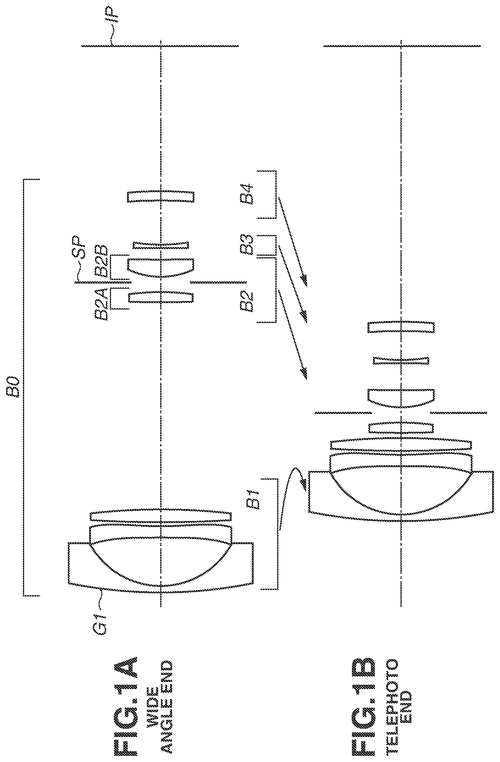
A and 1 B are cross-sectional views of a zoom lens according to a first exemplary embodiment.
A and 2 B are aberration diagrams of the zoom lens according to the first exemplary embodiment.
A and 3 B are cross-sectional views of a zoom lens according to a second exemplary embodiment.
A and 4 B are aberration diagrams of the zoom lens according to the second exemplary embodiment.
A and 5 B are cross-sectional views of a zoom lens according to a third exemplary embodiment.
A and 6 B are aberration diagrams of the zoom lens according to the third exemplary embodiment.
A and 7 B are cross-sectional views of a zoom lens according to a fourth exemplary embodiment.
A and 8 B are aberration diagrams of the zoom lens according to the fourth exemplary embodiment.
A and 9 B are cross-sectional views of a zoom lens according to a fifth exemplary embodiment.
A and 10 B are aberration diagrams of the zoom lens according to the fifth exemplary embodiment.
A and 11 B are cross-sectional views of a zoom lens according to a sixth exemplary embodiment.
A and 12 B are aberration diagrams of the zoom lens according to the sixth exemplary embodiment.
A and 13 B are cross-sectional views of a zoom lens according to a seventh exemplary embodiment.
A and 14 B are aberration diagrams of the zoom lens according to the seventh exemplary embodiment.
A and 15 B are cross-sectional views of a zoom lens according to an eighth exemplary embodiment.
A and 16 B are aberration diagrams of the zoom lens according to the eighth exemplary embodiment.
is a schematic diagram illustrating an image capturing apparatus.
DESCRIPTION OF THE EMBODIMENTS
A zoom lens and an image capturing apparatus including the same according to exemplary embodiments of the disclosure will be described below with reference to the attached drawings.
A and 1 B , A and 3 B , A and 5 B , A and 7 B , A and 9 B , A and 11 B , A and 13 B , and A and 15 B are cross-sectional views of zoom lenses B 0 of first, second, third, fourth, fifth, sixth, seventh, and eighth exemplary embodiments according to the disclosure, respectively. A , A , A , A , A , A , A , and A are cross-sectional views at a wide angle end, and B , B , B , B , B , B , B , and B are cross-sectional views at a telephoto end.
The zoom lens B 0 according to each of the exemplary embodiments is used for image capturing apparatuses, such as a digital still camera, a video camera, a silver-halide film camera, a camera for broadcast, and a projection apparatus, such as a projector. In each of the lens cross-sectional views, the left side is the object side (the enlargement side) and the right side is the image side (the reduction side).
In each of the lens cross-sectional views, “Bi” (“i” is a natural number) represents the “ith lens unit” where lens units included in the zoom lens B 0 are counted in order from the object side to the image side. The lens unit in the present disclosure is a component of the zoom lens B 0 and includes one or a plurality of lenses. The lenses in each of the lens units integrally move or remain in place during at least one of zooming and focusing, and the distance between the lens units adjacent to each other changes during at least one of zooming and focusing. In a case where optical members (such as a prism, a cover glass, and a filter) having substantially no refractive power are disposed at a position closest to the image or at a position closest to the object in the zoom lens B 0 , the optical members are not described as a part of the zoom lens.
An aperture stop SP determines (limits) the amount of light at a full aperture of F-number (Fno). An imaging plane IP is an image place where an image sensor (a photoelectric conversion element), such as a charge coupled device (CCD) sensor and a complementary metal oxide semiconductor (CMOS) sensor, is disposed in a case where the zoom lens B 0 according to each of the exemplary embodiments is used as an image-capturing optical system of a video camera or a digital still camera. In a case where the zoom lens B 0 according to each of the exemplary embodiments is used as an image-capturing optical system of a silver-halide camera, the photosensitive surface of a film is disposed at the imaging plane IP.
Arrows illustrated in each of the lens cross-sectional views each represent a simplified movement locus of each of the lens units in zooming from the wide angle end to the telephoto end. Each of the wide angle end and the telephoto end in the present disclosure refers to a zoom position of a state where each of the lens units is at an end of a corresponding mechanically movable range.
The zoom lens B 0 according to each of the exemplary embodiments includes a first lens unit B 1 having negative refractive power, a second lens unit B 2 having positive refractive power, and a third lens unit B 3 having negative refractive power, in order from the object side to the image side. Effects of the disclosure can also be effectively achieved even in a case where the zoom lens B 0 further includes another lens unit on the image side of the third lens unit B 3 .
In the zoom lens B 0 according to each of the exemplary embodiments, the first lens unit B 1 moves during zooming. The first lens unit B 1 includes a negative lens G 1 at a position closest to the object and at least one positive lens.
In the zoom lens B 0 according to each of the exemplary embodiments, lenses included in the second lens unit B 2 all have positive refractive power. In other words, the second lens unit B 2 consists only one or more positive lenses.
In the zoom lens B 0 according to each of the exemplary embodiments, the number of lenses included in the third lens unit B 3 is two or less, and the third lens unit B 3 moves toward the image side during focusing from infinity to close range.
The zoom lens B 0 according to each of the exemplary embodiments may have a function as an anti-vibration optical system by decentering one or a plurality of lenses in a direction including a component perpendicular to an optical axis in image blurring correction. Further, a parallel plate substantially having no refractive power, for example, a low-pass filter and an infrared cut filter, may be disposed between the lens disposed closest to the object side and the imaging plane IP.
A and 2 B , A and 4 B , A and 6 B , A and 8 B , A and 10 B , A and 12 B , A and 14 B , and A and 16 B are aberration diagrams each illustrating the zoom lens B 0 , and correspond to the first, second, third, fourth, fifth, sixth, seventh, and eighth exemplary embodiments, respectively. A , A , A , A , A , A , A , and A each illustrate aberration in an infinity in-focus state at the wide angle end, whereas B , B , B , B , B , B , B , and B each illustrate aberration in an infinity in-focus state at the telephoto end.
In each of the aberration diagrams, “Fno” indicates an F-number, and “ω” indicates a half angle of view (degree) that is an angle of view determined by paraxial calculation. A spherical aberration diagram illustrates a d-line (a wavelength of 587.6 nm) and a g-line (a wavelength of 435.8 nm).
A line S and a dotted line M in an astigmatism diagram represent the d-line at a sagittal image plane and the d-line at a meridional image plane, respectively. A distortion diagram illustrates the d-line. A chromatic aberration diagram illustrates a magnification chromatic aberration amount of the g-line with respect to the d-line.
A descriptions will be given of characteristics of the zoom lens B 0 according to each of the exemplary embodiments.
The zoom lens B 0 according to each of the exemplary embodiments is a negative-lead zoom lens. The third lens unit B 3 which has negative refractive power and of which diameter is easily reducible is configured to move during focusing, and therefore it is possible to achieve weight reduction of not only a focus lens unit, but also a holding mechanism for holding the focus lens unit as well as a drive mechanism for driving the focus lens unit. The third lens unit B 3 includes two lenses or less, and therefore the weight is further reduced.
In the zoom lens B 0 according to each of the exemplary embodiments, the first lens unit B 1 includes the negative lens G 1 at a position closest to the object. This is because, in a negative-lead zoom lens, the diameter of a lens closest to the object can be reduced by using a negative lens as the lens closest to the object. The first lens unit B 1 further includes at least one positive lens. The chromatic aberration of the first lens unit B 1 is thereby successfully corrected. In particular, because the first lens unit B 1 is the lens unit that moves during zooming, variations in magnification chromatic aberration and axial chromatic aberration that occur during zooming can be reduced by the above-describe configuration.
In the zoom lens B 0 according to each of the exemplary embodiments, the second lens unit B 2 consists only one or more positive lenses. The second lens unit B 2 functions as a main magnifying unit in the zoom lens B 0 according to each of the exemplary embodiments, and thus it is desirable to provide strong positive refractive power to the second lens unit B 2 . If a negative lens is added to the second lens unit B 2 , the refractive power of the positive lens in the second lens unit B 2 is required to be increased as much as the negative refractive power of the added negative lens. This increases the thickness of the second lens unit B 2 , and consequently weight reduction of the zoom lens B 0 is difficult to achieve.
The zoom lens B 0 according to each of the exemplary embodiments satisfies the following inequality (1): 1.40< Nd _ G 1<1.80 (1) where, Nd_G 1 is a refractive index in the d-line of the negative lens G 1 .
The inequality (1) defines the refractive index of the negative lens G 1 . In a case where the refractive index exceeds the upper limit of the inequality (1), it is difficult to obtain a material having low specific gravity, i.e., a material beneficial to weight reduction of the zoom lens B 0 . Meanwhile, in a case where the refractive index falls below the lower limit of the inequality (1), the volume of the negative lens G 1 increases when sufficient refractive power is provided to the negative lens G 1 , and consequently the weight reduction is difficult to achieve, which may not desirable. In addition, in the above-described case, the curvature radius of the negative lens G 1 on the image plane side is too small, and consequently it is difficult to successfully reduce or suppress occurrence of the field curvature and the astigmatism at the wide angle end in particular.
By satisfying the above-described configuration, the optical system in each of the exemplary embodiments achieves excellent optical performance while being light in weight.
As for the numerical range of the above-described inequality (1), it is more desirable to satisfy the following inequality (1a): 1.43< Nd _ G 1<1.79 (1a).
It is still more desirable for the numerical range of the above-described inequality (1) to satisfy the following inequality (1b): 1.45< Nd _ G 1<1.78 (1b).
Next, a description will be given of a desirable condition which is satisfied in the zoom lens B 0 according to each of the exemplary embodiments.
It is desirable for the zoom lens B 0 according to each of the exemplary embodiments to satisfy one or more of the following inequalities (2) to (6): 5.0<SF_ B 3 n< 0.50 (2), 1.0<| f 1|/ fw< 3.0 (3), 0.2< f 2/ fw< 5.0 (4), 0.1< f 3/ f 1<5.0 (5), and 18<ν d _ B 3 n< 36 (6).
SF_B 3 n is a shape factor SF of the negative lens having the strongest refractive power among the negative lenses included in the third lens unit B 3 (in a case where the third lens unit B 3 consists of one negative lens, the shape factor SF is for the one negative lens). The shape factor SF is an amount defined as: SF =( R 2+ R 1)/( R 2− R 1), where R 1 is the curvature radius of the lens surface on the image side, and R 2 is the curvature radius of the lens surface on the object side.
Further, fw is a focal length of the zoom lens B 0 at the wide angle end, f1 is a focal length of the first lens unit B 1 , f2 is a focal length of the second lens unit B 2 , f3 is a focal length of the third lens unit B 3 , and νd_B 3 n is an Abbe number in the d-line of the negative lens having the strongest refractive power among the negative lenses included in the third lens unit B 3 (in a case where the third lens unit B 3 consists of one negative lens, the Abbe number is for the one negative lens).
The inequality (2) defines the shape of the negative lens having the strongest refractive power among the negative lenses included in the third lens unit B 3 . In a case where the value falls below the lower limit of the inequality (2), it is difficult to successfully reduce or suppress a variation in the field curvature that occurs in focusing at the wide angle end, which may not desirable. In a case where the value exceeds the upper limit of the inequality (2), it is difficult to successfully reduce or suppress a variation in the spherical aberration that occurs in focusing at the telephoto end, which may not desirable.
The inequality (3) defines the ratio between the focal length of the first lens unit B 1 and the entire system focal length at the wide angle end. In a case where the value falls below the lower limit of the inequality (3), the refractive power of the first lens unit B 1 is too strong, and consequently it is difficult to successfully reduce or suppress the field curvature and the astigmatic difference occurring at the wide angle end. In a case where the value exceeds the upper limit of the inequality (3), the refractive power of the first lens unit B 1 is too weak, and consequently the front diameter (the diameter of the lens closest to the object) is too large. As a result, it is difficult to sufficiently reduce the weight of the zoom lens B 0 .
The inequality (4) defines the ratio between the focal length of the second lens unit B 2 and the entire system focal length at the wide angle end. In a case where the value falls below the lower limit of the inequality (4), the refractive power of the second lens unit B 2 is too strong, and consequently it is difficult to successfully reduce or suppress variations in the spherical aberration and the comatic aberration occurring from the wide angle end to the telephoto end. In a case where the value exceeds the upper limit of the inequality (4), the refractive power of the second lens unit B 2 is too weak, and consequently a movement amount of the second lens unit that is required for a desirable zoom ratio is too large. As a result, it is difficult to sufficiently reduce the weight of the zoom lens B 0 .
The inequality (5) defines the ratio between the focal length of the third lens unit B 3 and the focal length of the first lens unit B 1 . In a case where the value exceeds the upper limit of the inequality (5), the refractive power of the third lens unit B 3 is too weak, and consequently the movement amount during focusing increases. The increase in the movement amount enlarges the drive mechanism, and consequently it is difficult to sufficiently reduce the weight. In a case where the value falls below the lower limit of the inequality (5), the refractive power of the third lens unit B 3 is too strong, and consequently it is difficult to reduce a change in the optical performance during focusing to a sufficiently small amount.
The inequality (6) defines the Abbe number of the negative lens having the strongest refractive power among the negative lenses included in the third lens unit B 3 . In a case where the Abbe number is large to the extent that the Abbe number exceeds the upper limit of the inequality (6), the correction of the chromatic aberration in the entire zoom lens B 0 is insufficient, and consequently high optical performance is insufficiently achieved. In a case where the Abbe number is small to the extent that the Abbe number falls below the lower limit of the inequality (6), the correction of the chromatic aberration in the entire zoom lens B 0 is excessive, and consequently high optical performance is insufficiently achieved.
It is more desirable for the numerical ranges of the above-described inequalities (2) to (6) to satisfy the ranges represented by the following inequalities (2a) to (6a), respectively: −4.5<SF_ B 3 n< 0.30 (2a), 1.25<| f 1|/ fw< 2.6 (3a), 0.4< f 2/ fw< 3.0 (4a), 0.2< f 3/ f 1<3.5 (5a), and 19<ν d _ B 3 n< 34 (6a).
It is still more desirable for the numerical ranges of the above-described inequalities (2) to (6) to satisfy the ranges represented by the following inequalities (2b) to (6b), respectively: −4.0<SF_ B 3 n< 0.10 (2b), 1.5<| f 1|/ fw< 2.2 (3b), 0.5< f 2/ fw< 2.0 (4b), 0.3< f 3/ f 1<2.0 (5b), and 20<ν d _ B 3 n< 32 (6b).
Next, a description will be given of a desirable configuration which is satisfied in the zoom lens B 0 .
It is desirable for the zoom lens B 0 to be configured in such a manner that the number of the included lenses from the lens closest to the object in the second lens unit B 2 to the lens closest to the image in the zoom lens B 0 be five or less. This number of lenses includes the lens closest to the object in the second lens unit B 2 and the lens closest to the image in the zoom lens B 0 . With this configuration, the weight reduction is easily achieved while the zoom lens B 0 has desirable optical performance.
It is further desirable that the number of lenses included in the second lens unit B 2 be two or less. This also facilitates weight reduction while the zoom lens B 0 has desirable optical performance.
It is still further desirable that the third lens unit B 3 to consist of a single lens having negative refractive power. This also facilitates weight reduction while the zoom lens B 0 has desirable optical performance.
In addition, it is desirable for the first lens unit B 1 to include a lens having an aspherical surface (an aspherical lens). Having the aspherical lens reduces or suppresses the field curvature and the astigmatic difference occurring at the wide angle end. Further, it is desirable that the aspherical lens included in the first lens unit B 1 be a lens made of resin (a resin lens) because this facilitates the weight reduction.
Moreover, in the zoom lens B 0 according to each of the exemplary embodiments, it is desirable to correct camera shake by displacing a part or the whole of the second lens unit B 2 in a direction substantially perpendicular to the optical axis.
While, in the zoom lens B 0 according to each of the first to eighth exemplary embodiments, the focus lens unit is one lens unit, a plurality of lens units may be used as a focus unit. Such a focusing system is called floating.
Not only a refractive optical element (a lens) but also a diffractive optical element may also be used. Further, an optical path may be bent using a reflection optical member.
Next, a description in detail will be given of the zoom lens B 0 according to each of the exemplary embodiments.
First Exemplary Embodiment
As illustrated in A and 1 B , the zoom lens B 0 according to the first exemplary embodiment includes the first lens unit B 1 having negative refractive power, the second lens unit B 2 having positive refractive power, the third lens unit B 3 having negative refractive power, and a fourth lens unit B 4 having positive refractive power.
During zooming from the wide angle end to the telephoto end, the first lens unit B 1 moves toward the image side, and the second lens unit B 2 to the fourth lens unit B 4 move toward the object side. In this operation, the distance between the first lens unit B 1 and the second lens unit B 2 decreases, the distance between the second lens unit B 2 and the third lens unit B 3 increases, and the distance between the third lens unit B 3 and the fourth lens unit B 4 decreases. The second lens unit B 2 and the fourth lens unit B 4 move in the identical loci during zooming.
The third lens unit B 3 is the focus lens unit, and moves from the object side toward the image side during focusing from an infinity object to a close object. Image blurring (an image position) is corrected by moving the part of the second lens unit B 2 (the fourth lens, a sub-unit B 2 A) on the object side in a direction including a component substantially perpendicular to the optical axis.
Second Exemplary Embodiment
As illustrated in A and 3 B , the zoom lens B 0 according to the second exemplary embodiment includes the first lens unit B 1 having negative refractive power, the second lens unit B 2 having positive refractive power, the third lens unit B 3 having negative refractive power, and the fourth lens unit B 4 having positive refractive power.
During zooming from the wide angle end to the telephoto end, the first lens unit B 1 moves toward the image side, and the second lens unit B 2 to the fourth lens unit B 4 move toward the object side. In this operation, the distance between the first lens unit B 1 and the second lens unit B 2 decreases, the distance between the second lens unit B 2 and the third lens unit B 3 increases, and the distance between the third lens unit B 3 and the fourth lens unit B 4 decreases. The second lens unit B 2 and the fourth lens unit B 4 move in the identical loci during zooming.
The third lens unit B 3 is the focus lens unit, and moves from the object side toward the image side during focusing from the infinity object to the close object. Image blurring (the image position) is corrected by moving the part of the second lens unit B 2 (the fourth lens, the sub-unit B 2 A) on the object side in a direction including a component substantially perpendicular to the optical axis.
Third Exemplary Embodiment
As illustrated in A and 5 B , the zoom lens B 0 according to the third exemplary embodiment includes the first lens unit B 1 having negative refractive power, the second lens unit B 2 having positive refractive power, the third lens unit B 3 having negative refractive power, and the fourth lens unit B 4 having positive refractive power.
During zooming from the wide angle end to the telephoto end, the first lens unit B 1 moves toward the image side, and the second lens unit B 2 , the third lens unit B 3 , and the fourth lens unit B 4 move in the identical loci toward the object side. In this operation, the distance between the first lens unit B 1 and the second lens unit B 2 decreases.
The third lens unit B 3 is the focus lens unit, and moves from the object side toward the image side during focusing from the infinity object to the close object. Image blurring (the image position) is corrected by moving the part of the second lens unit B 2 (the fourth lens, the sub-unit B 2 A) on the object side in a direction including a component substantially perpendicular to the optical axis.
Fourth Exemplary Embodiment
As illustrated in A and 7 B , the zoom lens B 0 according to the fourth exemplary embodiment includes the first lens unit B 1 having negative refractive power, the second lens unit B 2 having positive refractive power, the third lens unit B 3 having negative refractive power, and the fourth lens unit B 4 having positive refractive power.
During zooming from the wide angle end to the telephoto end, the first lens unit B 1 moves toward the image side, and the second lens unit B 2 to the fourth lens unit B 4 move toward the object side. In this operation, the distance between the first lens unit B 1 and the second lens unit B 2 decreases, the distance between the second lens unit B 2 and the third lens unit B 3 increases, and the distance between the third lens unit B 3 and the fourth lens unit B 4 decreases. The second lens unit B 2 and the fourth lens unit B 4 move in the identical loci during zooming.
The third lens unit B 3 is the focus lens unit and moves from the object side toward the image side during focusing from the infinity object to the close object. Image blurring (the image position) is corrected by moving the second lens unit B 2 in a direction including a component substantially perpendicular to the optical axis.
Fifth Exemplary Embodiment
As illustrated in A and 9 B , the zoom lens B 0 according to the fifth exemplary embodiment includes the first lens unit B 1 having negative refractive power, the second lens unit B 2 having positive refractive power, the third lens unit B 3 having negative refractive power, and the fourth lens unit B 4 having negative refractive power.
During zooming from the wide angle end to the telephoto end, the first lens unit B 1 moves toward the image side, and the second lens unit B 2 to the fourth lens unit B 4 move toward the object side. In this operation, the distance between the first lens unit B 1 and the second lens unit B 2 decreases, the distance between the second lens unit B 2 and the third lens unit B 3 increases, and the distance between the third lens unit B 3 and the fourth lens unit B 4 decreases. The second lens unit B 2 and the fourth lens unit B 4 move in the identical loci during zooming.
The third lens unit B 3 is the focus lens unit, and moves from the object side toward the image side during focusing from the infinity object to the close object. Image blurring (the image position) is corrected by moving the part of the second lens unit B 2 (the fourth lens, the sub-unit B 2 A) on the object side in a direction including a component substantially perpendicular to the optical axis.
Sixth Exemplary Embodiment
As illustrated in A and 11 B , the zoom lens B 0 according to the sixth exemplary embodiment includes the first lens unit B 1 having negative refractive power, the second lens unit B 2 having positive refractive power, the third lens unit B 3 having negative refractive power, and the fourth lens unit B 4 having positive refractive power.
During zooming from the wide angle end to the telephoto end, the first lens unit B 1 moves toward the image side, and the second lens unit B 2 , the third lens unit B 3 , and the fourth lens unit B 4 move in the identical loci toward the object side. In this operation, the distance between the first lens unit B 1 and the second lens unit B 2 decreases.
The third lens unit B 3 is the focus lens unit, and moves from the object side toward the image side during focusing from the infinity object to the close object. Image blurring (the image position) is corrected by moving the part of the second lens unit B 2 (the fourth lens, the sub-unit B 2 A) on the object side in a direction including a component substantially perpendicular to the optical axis.
Seventh Exemplary Embodiment
As illustrated in A and 13 B , the zoom lens B 0 according to the seventh exemplary embodiment includes the first lens unit B 1 having negative refractive power, the second lens unit B 2 having positive refractive power, and the third lens unit B 3 having negative refractive power.
During zooming from the wide angle end to the telephoto end, the first lens unit B 1 moves toward the image side, the second lens unit B 2 moves toward the object side, and the third lens unit B 3 moves toward the object side. In this operation, the distance between the first lens unit B 1 and the second lens unit B 2 decreases, and the distance between the second lens unit B 2 and the third lens unit B 3 increases.
The third lens unit B 3 is the focus lens unit, and moves from the object side toward the image side during focusing from the infinity object to the close object. Image blurring (the image position) is corrected by moving the part of the second lens unit B 2 (the fourth lens, the sub-unit B 2 A) on the object side in a direction including a component substantially perpendicular to the optical axis.
Eighth Exemplary Embodiment
As illustrated in A and 15 B , the zoom lens B 0 according to the eighth exemplary embodiment includes the first lens unit B 1 having negative refractive power, the second lens unit B 2 having positive refractive power, and the third lens unit B 3 having negative refractive power.
During zooming from the wide angle end to the telephoto end, the first lens unit B 1 moves toward the image side, the second lens unit B 2 moves toward the object side, and the third lens unit B 3 moves toward the object side. In this operation, the distance between the first lens unit B 1 and the second lens unit B 2 decreases, and the distance between the second lens unit B 2 and the third lens unit B 3 increases.
The third lens unit B 3 is the focus lens unit, and moves from the object side toward the image side during focusing from the infinity object to the close object. Image blurring (the image position) is corrected by moving the part of the second lens unit B 2 (the fourth lens, the sub-unit B 2 A) on the object side in a direction including a component substantially perpendicular to the optical axis.
Next, first to eighth numeric examples corresponding to the first to eighth exemplary embodiments, respectively, will be described.
In surface data of each of the first to eighth numeric examples, r represents the curvature radius of each optical surface, and d (mm) represents the axial distance (the distance in the optical axis) between an mth surface and an (m+1)th surface, where m is a number assigned to each surface and numbered from the light incidence side. Further, nd represents the refractive index for the d-line of each optical member, and νd represents the Abbe number of the optical member. The Abbe number νd of a certain material is expressed as: ν d =( Nd− 1)/( NF−NC ), where Nd, NF, NC, and Ng are a refractive index in a d-line (587.56 nm), a refractive index in an F-line (486.1 nm), a refractive index in a C-line (656.3 nm), and a refractive index in a g-line (a wavelength of 435.835 nm), respectively, of the Fraunhofer's lines.
In each of the first to eighth numeric examples, each of a focal length (mm), a F-number, and a half angle of view (degree) is a value in the case of when the zoom lens B 0 according to the corresponding exemplary embodiment is focused on the infinity object. Back focus BF is an air equivalent length from the last lens surface to the image plane. A total lens length is a value calculated by adding the back focus BF to the distance in the optical axis from the first lens surface to the last lens surface.
In the surface data, “*” of the surface number indicates the surface having an aspherical shape. The aspherical shape is expressed by the following expression (1):
X = H 2 / R 1 + 1 - ( 1 + K ) ( H / R ) 2 + A 4 · H 4 + A 6 · H 6 + A 8 · H 8 + A 10 · H 10 + A 12 · H 12 + A 14 · H 14 + A 16 · H 16 ( 1 ) where X is an X-axis in the optical axis direction, H is an H-axis in the direction perpendicular to the optical axis, while a light traveling direction is positive, R is a paraxial curvature radius, K is a conic constant, and Aj is a jth-order aspherical surface coefficient. In the aspherical coefficient, “e−y” indicates 10 −y .
First Numeric Example
Surface Data
Surface Effective
Number r d nd νd Diameter
1 81.305 1.15 1.63854 55.4 31.11
2 14.228 8.51 23.92
3* −1000.000 2.00 1.53110 55.9 23.61
4* 54.155 0.70 23.70
5 201.759 2.26 1.84666 23.8 23.47
6 −109.647 (Variable) 23.24
7 154.918 1.80 1.51742 52.4 10.00
8 −41.663 1.69 10.19
9 (Stop) ∞ 1.00 10.33
10 13.449 3.04 1.59522 67.7 10.47
11 519.400 (Variable) 9.94
12 −462.121 0.60 1.84666 23.8 8.86
13 29.053 (Variable) 8.66
14* −144.347 1.64 1.58313 59.4 9.90
15 −64.118 (Variable) 10.53
Image Plane ∞
Aspherical Data
Third Surface
K = 0 A4 = −6.16999e−005 A6 = 9.64091e−008
A8 = −6.24666e−010 A10 = 1.15838e−011 A12 = 5.52161e−014
Fourth Surface
K = 0 A4 = −7.58020e−005 A6 = −6.07857e−010
A8 = 1.24373e−009 A10 = −5.09126e−012 A12 = −7.700126−015
Fourteenth Surface
K = 0 A4 = −8.02055e−005 A6 = −6.36693e−007
A8 = −8.04272e−010 A10 = −6.04362e−011
Various Data
Zoom Ratio 2.82
Wide-Angle Intermediate Telephoto
Focal length 15.46 24.00 43.65
F-number 4.16 4.92 6.50
Half Angle of View (Degree) 38.73 29.65 17.38
Image Height 12.40 13.66 13.66
Total Lens Length 96.84 85.69 84.27
BF 26.19 34.03 49.18
d6 36.48 17.48 0.92
d11 1.54 1.60 2.61
d13 8.25 8.19 7.18
d15 26.19 34.03 49.18
Zoom Lens Unit Data
Front Rear
Lens Principal Principal
Start Focal Configuration Point Point
Unit Surface Length Length Position Position
1 1 −29.62 14.62 −0.18 −13.24
2 7 17.56 7.52 3.13 −2.75
3 12 −32.27 0.60 0.31 −0.02
4 14 196.35 1.64 1.85 0.82
Single Lens Data
Lens Start Surface Focal Length
1 1 −27.19
2 3 −96.67
3 5 84.19
4 7 63.65
5 10 23.14
6 12 −32.27
7 14 196.35
Second Numeric Example
Surface Data
Surface Effective
Number r d nd νd Diameter
1 26.941 1.00 1.63854 55.4 24.79
2 12.045 7.49 20.24
3* −1000.000 1.70 1.53110 55.9 19.64
4* 33.260 0.40 19.29
5 46.469 1.94 1.84666 23.8 19.03
6 174.749 (Variable) 18.63
7 139.916 1.73 1.69680 55.5 8.98
8 −44.483 1.00 9.12
9 (Stop) ∞ 1.50 9.16
10 16.314 2.57 1.77250 49.6 9.23
11 156.410 (Variable) 8.76
12 −384.505 0.70 1.84666 23.8 7.92
13 20.582 (Variable) 7.71
14* −312.236 2.08 1.53110 55.9 10.79
15* −28.811 (Variable) 11.46
Image Plane ∞
Aspherical Data
Third Surface
K = 0 A4 = −1.41463e−004 A6 = 7.66013e−007
A8 = −1.27190e−009 A10 = −1.10963e−011
Fourth Surface
K = 0 A4 = −1.69055e−004 A6 = 8.63631e−007
A8 = −2.53183e−009 A10 = −7.27576e−012
Fourteenth Surface
K = 0 A4 = −9.44164e−006 A6 = 5.54551e−007
A8 = −1.94972e−008 A10 = 2.35602e−010
Fifteenth Surface
K = 0 A4 = 3.12388e−005 A6 = 2.31800e−007
Various Data
Zoom Ratio 2.35
Wide-Angle Intermediate Telephoto
Focal Length 18.53 30.00 43.65
F-number 4.56 5.48 6.50
Half Angle of View (Degree) 33.78 24.48 17.38
Image Height 12.40 13.66 13.66
Total Lens Length 89.11 81.23 81.40
BF 28.48 38.21 47.77
d6 28.48 10.86 1.48
d11 1.53 1.64 2.28
d13 8.52 8.41 7.77
d15 28.48 38.21 47.77
Zoom Lens Unit Data
Front Rear
Lens Principal Principal
Start Focal Configuration Point Point
Unit Surface Length Length Position Position
1 1 −31.01 12.52 1.87 −8.64
2 7 16.38 6.79 2.58 −2.47
3 12 −23.06 0.70 0.36 −0.02
4 14 59.61 2.08 1.50 0.14
Single Lens Data
Lens Start Surface Focal Length
1 1 −35.03
2 3 −60.57
3 5 74.25
4 7 48.63
5 10 23.39
6 12 −23.06
7 14 59.61
Third Numeric Example
Surface Data
Surface Effective
Number r d nd νd Diameter
1 35.854 1.00 1.77250 49.6 26.50
2 14.573 7.47 22.24
3* −1000.000 1.70 1.53110 55.9 21.69
4* 45.253 0.40 21.52
5 42.410 2.16 1.85478 24.8 21.16
6 140.853 (Variable) 20.73
7 128.816 1.73 1.67790 55.3 9.08
8 −46.174 1.00 9.20
9 (Stop) ∞ 1.50 9.21
10 15.569 2.03 1.88300 40.8 9.23
11 134.614 (Variable) 8.83
12 −133.172 0.70 1.84666 23.8 8.13
13 17.103 (Variable) 7.86
14* −181.303 2.43 1.53110 55.9 9.56
15* −26.048 (Variable) 10.37
Image Plane ∞
Aspherical Data
Third Surface
K = 0 A4 = −1.42036e−004 A6 = 6.81082e−007
A8 = −1.27645e−009 A10 = −2.59087e−012
Fourth Surface
K = 0 A4 = −1.54470e−004 A6 = 8.17822e−007
A8 = −2.40245e−009 A10 = 7.64264e−013
Fourteenth Surface
K = 0 A4 = 3.90803e−005 A6 = 2.26763e−006
A8 = −3.71828e−008 A10 = 5.18172e−010
Fifteenth Surface
K = 0 A4 = 6.95347e−005 A6 = 1.53424e−006
Various Data
Zoom Ratio 2.35
Wide-Angle Intermediate Telephoto
Focal Length 18.53 30.00 43.65
F-number 4.53 5.43 6.50
Half Angle of View (Degree) 33.78 24.48 17.38
Image Height 12.40 13.66 13.66
Total Lens Length 92.00 80.75 81.34
BF 29.45 38.60 49.50
d6 32.32 11.91 1.60
d11 1.58 1.58 1.58
d13 6.54 6.54 6.54
d15 29.45 38.60 49.50
Zoom Lens Unit Data
Front Rear
Lens Principal Principal
Start Focal Configuration Point Point
Unit Surface Length Length Position Position
1 1 −35.20 12.73 0.44 −10.40
2 7 14.75 6.25 2.72 −1.98
3 12 −17.86 0.70 0.34 −0.04
4 14 56.97 2.43 1.84 0.26
Single Lens Data
Lens Start Surface Focal Length
1 1 −32.45
2 3 −81.47
3 5 70.28
4 7 50.34
5 10 19.78
6 12 −17.86
7 14 56.97
Fourth Numeric Example
Surface Data
Surface Effective
Number r d nd νd Diameter
1 45.893 1.00 1.63854 55.4 27.09
2 14.386 7.03 22.30
3 −85.298 1.70 1.53110 55.9 21.78
4* 97.643 0.40 21.12
5 23.337 2.24 1.84666 23.8 20.54
6 34.716 (Variable) 19.79
7 (Stop) ∞ 1.00 9.02
8* 16.308 2.56 1.77250 49.6 9.36
9 −58.463 (Variable) 9.12
10 42172.073 0.60 1.80810 22.8 8.03
11 19.038 (Variable) 7.82
12* −263.369 2.08 1.53110 55.9 10.58
13 −27.990 (Variable) 11.27
Image Plane ∞
Aspherical Data
Fourth Surface
K = 0 A4 = −4.47785e−006 A6 = 4.80655e−008
A8 = −5.32262e−010 A10 = 1.27701e−012
Eighth Surface
K = 0 A4 = −3.43112e−005 A6 = 3.14927e−008
A8 = −2.95172e−009 A10 = 4.26192e−011
Twelfth Surface
K = 0 A4 = −3.22505e−005 A6 = 1.56251e−007
A8 = −1.96015e−008 A10 = 3.12929e−010
Various Data
Zoom Ratio 2.35
Wide-Angle Intermediate Telephoto
Focal Length 18.53 26.00 43.60
F-number 4.56 5.17 6.50
Half Angle of View (Degree) 33.79 27.72 17.40
Image Height 12.40 13.66 13.66
Total Lens Length 91.32 83.11 80.48
BF 29.73 36.16 48.88
d6 32.64 18.00 2.64
d9 2.37 2.28 2.75
d11 7.98 8.08 7.61
d13 29.73 36.16 48.88
Zoom Lens Unit Data
Front Rear
Lens Principal Principal
Start Focal Configuration Point Point
Unit Surface Length Length Position Position
1 1 −34.13 12.37 1.21 −8.90
2 7 16.76 3.56 1.32 −1.14
3 10 −23.57 0.60 0.33 0.00
4 12 58.79 2.08 1.51 0.16
Single Lens Data
Lens Start Surface Focal Length
1 1 −33.23
2 3 −85.45
3 5 77.13
4 8 16.76
5 10 −23.57
6 12 58.79
Fifth Numeric Example
Surface Data
Surface Effective
Number r d nd νd Diameter
1 51.714 1.15 1.72916 54.7 30.45
2 15.131 9.48 24.47
3* −68.368 2.00 1.53110 55.9 23.99
4* −1234.568 0.30 24.30
5 −202.690 2.04 1.84666 23.8 24.02
6 −65.810 (Variable) 23.91
7 211.787 1.75 1.60311 60.6 10.34
8 −48.064 1.71 10.50
9 (Stop) ∞ 1.00 10.59
10 12.750 2.89 1.51823 58.9 10.70
11 −61.135 (Variable) 10.28
12 −53.415 0.60 1.85478 24.8 9.18
13 52.610 (Variable) 8.98
14* 444.819 1.50 1.53110 55.9 9.76
15 95.657 (Variable) 10.33
Image Plane ∞
Aspherical Data
Third Surface
K = 0 A4 = −6.37596e−005 A6 = 5.59365e−007
A8 = −6.75504e−009 A10 = 4.19523e−011 A12 = −1.04577e−013
Fourth Surface
K = 0 A4 = −6.85609e−005 A6 = 4.64163e−007
A8 = −5.211226−009 A10 = 2.99013e−011 A12 = −7.12555e−014
Fourteenth Surface
K = 0 A4 = −1.15845e−004 A6 = −7.75571e−007
A8 = −3.94565e−009 A10 = −5.60854e−011
Various Data
Zoom Ratio 2.66
Wide-Angle Intermediate Telephoto
Focal Length 16.41 24.00 43.65
F-number 4.21 4.90 6.50
Half Angle of View (Degree) 37.08 29.65 17.38
Image Height 12.40 13.66 13.66
Total Lens Length 99.00 87.77 83.61
BF 24.60 31.13 45.64
d6 39.49 21.74 3.07
d11 1.49 1.49 2.08
d13 8.99 9.00 8.40
d15 24.60 31.13 45.64
Zoom Lens Unit Data
Front Rear
Lens Principal Principal
Start Focal Configuration Point Point
Unit Surface Length Length Position Position
1 1 −32.74 14.97 −0.48 −14.20
2 7 16.29 7.36 3.46 −2.41
3 12 −30.93 0.60 0.16 −0.16
4 14 −229.80 1.50 1.25 0.27
Single Lens Data
Lens Start Surface Focal Length
1 1 −29.73
2 3 −136.36
3 5 114.32
4 7 65.12
5 10 20.63
6 12 −30.93
7 14 −229.80
Sixth Numeric Example
Surface Data
Surface Effective
Number r d nd νd Diameter
1 32.515 1.00 1.67790 55.3 25.08
2 13.169 6.71 20.91
3* −1000.000 1.70 1.53110 55.9 20.46
4* 45.486 0.40 20.10
5 23.627 2.02 2.00069 25.5 19.69
6 34.676 (Variable) 19.02
7 115.005 1.73 1.72916 54.7 9.08
8 −48.763 1.00 9.14
9 (Stop) ∞ 1.50 9.05
10 14.904 2.63 1.72916 54.7 8.93
11 −272.635 (Variable) 8.42
12 −35.401 0.70 1.90366 31.3 7.72
13 17.894 (Variable) 7.53
14* −80.549 2.34 1.53110 55.9 8.98
15* −13.809 (Variable) 9.84
Image Plane ∞
Aspherical Data
Third Surface
K = 0 A4 = −2.82744e−005 A6 = −4.01528e−007
A8 = 4.70130e−009 A10 = −1.93064e−011
Fourth Surface
K = 0 A4 = −3.88075e−005 A6 = −4.28587e−007
A8 = 4.87774e−009 A10 = −2.07859e−011
Fourteenth Surface
K = 0 A4 = −4.11964e−005 A6 = 6.94293e−007
A8 = −5.20928e−008 A10 = 1.13182e−009
Fifteenth Surface
K = 0 A4 = −8.49430e−006 A6 = −1.54892e−007
Various Data
Zoom Ratio 2.18
Wide-Angle Intermediate Telephoto
Focal Length 20.01 27.00 43.65
F-number 4.60 5.15 6.50
Half Angle of View (Degree) 31.79 26.84 17.38
Image Height 12.40 13.66 13.66
Total Lens Length 92.00 84.32 83.15
BF 33.77 39.37 52.69
d6 30.31 17.03 2.54
d11 1.63 1.63 1.63
d13 4.57 4.57 4.57
d15 33.77 39.37 52.69
Zoom Lens Unit Data
Front Rear
Lens Principal Principal
Start Focal Configuration Point Point
Unit Surface Length Length Position Position
1 1 −35.80 11.83 1.24 −8.34
2 7 14.40 6.86 2.83 −2.33
3 12 −13.07 0.70 0.24 −0.12
4 14 31.00 2.34 1.82 0.31
Single Lens Data
Lens Start Surface Focal Length
1 1 −33.35
2 3 −81.87
3 5 67.89
4 7 47.17
5 10 19.46
6 12 −13.07
7 14 31.00
Seventh Numeric Example
Surface Data
Surface Effective
Number r d nd νd Diameter
1 48.059 1.00 1.63854 55.4 26.32
2 14.114 7.33 21.64
3* −1000.000 1.70 1.53110 55.9 21.08
4* 51.376 0.40 20.96
5 49.503 1.99 1.84666 23.8 20.55
6 177.062 (Variable) 20.15
7 127.256 1.73 1.67790 55.3 9.12
8 −47.359 1.00 9.25
9 (Stop) ∞ 1.50 9.27
10 17.235 2.61 1.80400 46.6 9.31
11 358.823 (Variable) 8.84
12 −117.524 0.70 1.84666 23.8 8.08
13 21.736 7.12 7.87
14* −221.529 2.41 1.53110 55.9 10.05
15* −28.819 (Variable) 10.82
Image Plane ∞
Aspherical Data
Third Surface
K = 0 A4 = −1.24978e−004 A6 = 2.71294e−007
A8 = 1.41979e−009 A10 = −9.72356e−012
Fourth Surface
K = 0 A4 = −1.37193e−004 A6 = 3.71703e−007
A8 = 7.25801e−010 A10 = −7.69387e−012
Fourteenth Surface
K = 0 A4 = 4.49135e−005 A6 = 1.54680e−006
A8 = −2.35020e−008 A10 = 2.913196−010
Fifteenth Surface
K = 0 A4 = 7.57248e−005 A6 = 1.14052e−006
Various Data
Zoom Ratio 2.36
Wide-Angle Intermediate Telephoto
Focal Length 18.53 27.00 43.65
F-number 4.56 5.23 6.50
Half Angle of View (Degree) 33.79 26.84 17.38
Image Height 12.40 13.66 13.66
Total Lens Length 92.00 82.86 81.68
BF 29.46 36.42 48.75
d6 31.48 15.36 1.50
d11 1.56 1.59 1.93
d15 29.46 36.42 48.75
Zoom Lens Unit Data
Front Rear
Lens Principal Principal
Start Focal Configuration Point Point
Unit Surface Length Length Position Position
1 1 −33.74 12.42 0.44 −10.21
2 7 16.19 6.84 2.71 −2.37
3 12 −42.61 10.23 −5.84 −17.47
Single Lens Data
Lens Start Surface Focal Length
1 1 −31.66
2 3 −91.96
3 5 80.58
4 7 51.12
5 10 22.44
6 12 −21.62
7 14 62.11
Eighth Numeric Example
Surface Data
Surface Effective
Number r d nd νd Diameter
1 26.077 1.00 1.48749 70.2 20.69
2 11.855 6.10 17.78
3* −46.388 1.70 1.53110 55.9 17.07
4 66.382 0.40 16.45
5 18.651 2.51 1.51742 52.4 16.13
6 49.111 (Variable) 15.55
7 (Stop) ∞ 1.00 4.92
8 38.354 1.54 1.49700 81.5 5.00
9 −53.188 1.47 5.01
10 8.415 1.67 1.56732 42.8 4.95
11 27.462 (Variable) 4.61
12 15.014 0.60 1.82115 24.1 4.57
13* 7.963 (Variable) 4.57
Image Plane ∞
Aspherical Data
Third Surface
K = 0 A4 = 2.68514e−007 A6 = 3.76986e−008
A8 = −7.83455e−010 A10 = 4.73817e−012
Thirteenth Surface
K = 0 A4 = 1.28808e−004 A6 = −1.62031e−005
A8 = 3.98366e−006 A10 = −2.76591e−007
Various Data
Zoom Ratio 1.45
Wide-Angle Intermediate Telephoto
Focal Length 24.50 26.73 35.50
F-number 9.41 9.73 11.00
Half Angle of View (Degree) 26.84 27.07 21.05
Image Height 12.40 13.66 13.66
Total Lens Length 85.00 82.28 76.68
BF 36.70 38.07 43.53
d6 28.80 24.69 13.57
d11 1.50 1.52 1.59
d13 36.70 38.07 43.53
Zoom Lens Unit Data
Front Rear
Lens Principal Principal
Start Focal Configuration Point Point
Unit Surface Length Length Position Position
1 1 −41.72 11.71 1.67 −8.18
2 7 14.56 5.69 2.57 −2.01
3 12 −21.47 0.60 0.73 0.39
Single Lens Data
Lens Start Surface Focal Length
1 1 −45.64
2 3 −51.15
3 5 56.53
4 8 45.09
5 10 20.73
6 12 −21.47
Various values in each of the first to eighth numeric examples are summarized in the following Table 1.
TABLE 1
First Second Third Fourth Fifth Sixth Seventh Eighth
Example Example Example Example Example Example Example Example
Nd_G1 1.6385 1.6385 1.7725 1.6385 1.7292 1.6779 1.6385 1.4875
SF_B3n −0.88 −0.90 −0.77 −1.00 −0.01 −0.33 −0.69 −3.26
|f1|/fw 1.92 1.67 1.90 1.84 2.00 1.79 1.82 1.70
f2/fw 1.14 0.88 0.80 0.90 0.99 0.72 0.87 0.59
f3/f1 1.09 0.74 0.51 0.69 0.94 0.37 1.26 0.51
νd_B3n 23.78 23.78 23.78 22.76 24.80 31.32 23.78 24.06
[Image Capturing Apparatus]
Next, a description will be given of an exemplary embodiment with reference to in which a digital still camera (an image capturing apparatus) 10 employs the zoom lens according to any of the exemplary embodiments as an imaging optical system. illustrates a camera body 13 and an image-capturing optical system 11 including the zoom lens B 0 described in any of the first to eighth exemplary embodiments. A solid-state image sensor (a photoelectric conversion element) 12 , such as a CCD sensor and CMOS sensor, is disposed in the camera body 13 . The solid-state image sensor 12 receives an optical image formed by the image-capturing optical system 11 , and photoelectrically converts the received optical image. The camera body 13 may be a single-lens reflex camera having a quick turn mirror, or may be a mirrorless camera not having a quick turn mirror.
In the above-described way, the zoom lens according to any of the exemplary embodiments of the disclosure is applied to the image capturing apparatus, such as a digital still camera, whereby an image capturing apparatus having excellent optical performance while being light in weight can be obtained.
The zoom lens according to each of the above-described exemplary embodiments is not limited to the image capturing apparatus, such as a digital still camera, and is applicable to various optical apparatuses, such as a telescope.
Some exemplary embodiments and examples of the disclosure are described above, but the disclosure is not limited to these exemplary embodiments and examples, and various combinations, alterations, and modifications can be made without departing from the scope of the disclosure.
While the disclosure has been described with reference to exemplary embodiments, it is to be understood that the disclosure is not limited to the disclosed exemplary embodiments. The scope of the following claims is to be accorded the broadest interpretation so as to encompass all such modifications and equivalent structures and functions.
This application claims the benefit of Japanese Patent Application No. 2019-215441, filed Nov. 28, 2019, which is hereby incorporated by reference herein in its entirety.
Figures (17)
Citations
This patent cites (15)
- US5999329
- US8472125
- US2006/0245078
- US2007/0019302
- US2014/0022416
- US2014/0354858
- US2018/0275383
- US2019/0094490
- US101029959
- US101191896
- US104423025
- USH11-084242
- US2005-275280
- US2014-178388
- US2014-235190