Abstract
The disclosure provides an optical imaging system, which has a first optical axis, a second optical axis perpendicular to the first optical axis and a third optical axis perpendicular to the second optical axis, the first optical axis is parallel to the third optical axis, the optical imaging system includes: a first imaging lens group, including a first refraction optical element that deflects light entering along a direction of the first optical axis to be propagated along a direction of the second optical axis; a second imaging lens group, sequentially including from an object side to an image side along the second optical axis a first lens to a seventh lens with refractive power; a third imaging lens group, including a second refraction optical element that deflects light entering along the direction of the second optical axis to be propagated along a direction of the third optical axis.
Claims (20)
1. An optical imaging system, having a first optical axis, a second optical axis perpendicular to the first optical axis and a third optical axis perpendicular to the second optical axis, wherein the first optical axis is parallel to the third optical axis, the optical imaging system comprises: a first imaging lens group, arranged along the first optical axis and comprising a first refraction optical element configured to deflect light entering along a direction of the first optical axis to be propagated along a direction of the second optical axis; a second imaging lens group, sequentially comprising from an object side to an image side along the second optical axis: a first lens, a second lens, a third lens, a fourth lens, a fifth lens, a sixth lens and a seventh lens with refractive power respectively; and a third imaging lens group, arranged along the third optical axis and comprising a second refraction optical element configured to deflect light entering along the direction of the second optical axis to be propagated along a direction of the third optical axis; wherein TTLz is a distance from an object-side end of the first imaging lens group to an imaging surface of the optical imaging system in a direction parallel to the direction of the third optical axis, and TTLz and a total effective focal length f of the optical imaging system satisfy TTLz/f<0.7.
14. An optical imaging system, having a first optical axis, a second optical axis perpendicular to the first optical axis and a third optical axis perpendicular to the second optical axis, wherein the first optical axis is parallel to the third optical axis, the optical imaging system comprises: a first imaging lens group, arranged along the first optical axis and comprising a first refraction optical element configured to deflect light entering along a direction of the first optical axis to be propagated along a direction of the second optical axis; a second imaging lens group, sequentially comprising, from an object side to an image side along the second optical axis, a first lens, a second lens, a third lens, a fourth lens, a fifth lens, a sixth lens and a seventh lens with refractive power respectively; and a third imaging lens group, arranged along the third optical axis and comprising a second refraction optical element configured to deflect light entering along the direction of the second optical axis to be propagated along a direction of the third optical axis; wherein an optical distortion Dist of the optical imaging system satisfies |Dist|<0.1%.
Show 18 dependent claims
2. The optical imaging system according to claim 1 , wherein an optical distortion Dist of the optical imaging system satisfies |Dist|<0.1%.
3. The optical imaging system according to claim 1 , wherein an effective focal length f1 of the first lens and an effective focal length f4 of the fourth lens satisfy 0<f1/f4<1.0.
4. The optical imaging system according to claim 1 , wherein an effective focal length f2 of the second lens, an effective focal length f6 of the sixth lens and an effective focal length f7 of the seventh lens satisfy 0.5<(f2+f6)/f7<2.0.
5. The optical imaging system according to claim 1 , wherein the first refraction optical element is a first prism, and the second refraction optical element is a second prism.
6. The optical imaging system according to claim 5 , wherein ΣCT is a sum of thicknesses of any lens in the first lens to the seventh lens on the second optical axis, PL1 is a sum of a thickness of the first prism on the first optical axis and a thickness of the first prism on the second optical axis, and ΣCT and PL1 satisfy 0.5<ΣCT/PL1<1.0.
7. The optical imaging system according to claim 5 , wherein ΣAT is a sum of spacing distances of any two adjacent lenses in the first lens to the seventh lens on the second optical axis, PL2 is a sum of a thickness of the second prism on the second optical axis and a thickness of the second prism on the third optical axis, and ΣAT and PL2 satisfy 0.3<ΣAT/PL2<0.8.
8. The optical imaging system according to claim 1 , wherein a curvature radius R1 of an object-side surface of the first lens, a curvature radius R3 of an object-side surface of the second lens and a curvature radius R4 of an image-side surface of the second lens satisfy 0.3<R1/(R3−R4)<1.3.
9. The optical imaging system according to claim 1 , wherein a curvature radius R6 of an image-side surface of the third lens and a curvature radius R7 of an object-side surface of the fourth lens may satisfy 0.5<R6/R7<1.5.
10. The optical imaging system according to claim 1 , wherein a curvature radius R14 of an image-side surface of the seventh lens and the total effective focal length f of the optical imaging system may satisfy 0<R14/f<1.0.
11. The optical imaging system according to claim 1 , wherein a center thickness CT1 of the first lens on the second optical axis, a center thickness CT6 of the sixth lens on the second optical axis and a center thickness CT7 of the seventh lens on the second optical axis may satisfy 0<CT6/(CT1+CT7)<1.0.
12. The optical imaging system according to claim 1 , wherein a center thickness CT4 of the fourth lens on the second optical axis, a center thickness CT5 of the fifth lens on the second optical axis and a spacing distance T45 of the fourth lens and the fifth lens on the second optical axis may satisfy 0.6<(CT4+CT5)/T45<1.6.
13. The optical imaging system according to claim 1 , wherein the first lens has a positive refractive power, and an object-side surface thereof is a convex surface; the second lens has a negative refractive power; an image-side surface of the third lens is a concave surface; the fourth lens has a positive refractive power, and an object-side surface thereof is a convex surface; and an image-side surface of the seventh lens is a concave surface.
15. The optical imaging system according to claim 14 , wherein an effective focal length f1 of the first lens and an effective focal length f4 of the fourth lens may satisfy 0<f1/f4<1.0.
16. The optical imaging system according to claim 15 , wherein TTLz is a distance from an object-side end of the first imaging lens group to an imaging surface of the optical imaging system in a direction parallel to the direction of the third optical axis, and TTLz and a total effective focal length f of the optical imaging system may satisfy TTLz/f<0.7.
17. The optical imaging system according to claim 14 , wherein an effective focal length f2 of the second lens, an effective focal length f6 of the sixth lens and an effective focal length f7 of the seventh lens may satisfy 0.5<(f2+f6)/f7<2.0.
18. The optical imaging system according to claim 14 , wherein the first refraction optical element is a first prism, and the second refraction optical element is a second prism.
19. The optical imaging system according to claim 18 , wherein ΣCT is a sum of thicknesses of any lens in the first lens to the seventh lens on the second optical axis, PL1 is a sum of a thickness of the first prism on the first optical axis and a thickness of the first prism on the second optical axis, and ΣCT and PL1 may satisfy 0.5<ΣCT/PL1<1.0.
20. The optical imaging system according to claim 18 , wherein ΣAT is a sum of spacing distances of any two adjacent lenses in the first lens to the seventh lens on the second optical axis, PL2 is a sum of a thickness of the second prism on the second optical axis and a thickness of the second prism on the third optical axis, and ΣAT and PL2 may satisfy 0.3<ΣAT/PL2<0.8.
Full Description
Show full text →
CROSS-REFERENCE TO RELATED PRESENT INVENTION(S)
The disclosure claims priority to and the benefit of Chinese Patent Present invention No. 202011140001.8, filed in the China National Intellectual Property Administration (CNIPA) on 22 Oct. 2020, which is incorporated herein by reference in its entirety.
TECHNICAL FIELD
The disclosure relates to the technical field of optical elements, and more particularly to an optical imaging system.
BACKGROUND
With the upgrading of consumer electronic products and the development of image software functions and video software functions in consumer electronic products, requirements of consumers on the shooting quality of electronic products such as mobile phones have been constantly increased. Meanwhile, consumers expect electronic products such as mobile phones to be lighter, thinner and have a characteristic of miniaturization.
Camera modules are usually arranged in portable devices such as mobile phones to endow the mobile phones with camera functions. There is usually arranged in a camera module a Charge-Coupled Device (CCD) type image sensor or a Complementary Metal Oxide Semiconductor (CMOS) type image sensor as well as an optical imaging system. The optical imaging system may converge light of an object side, imaged light follows a light path of the optical imaging system and irradiates the image sensor, and furthermore, the image sensor converts an optical signal into an electric signal to form image data.
The optical imaging system configured in the camera module includes a telephoto lens usually with a relatively long structure size. There is a need for an optical imaging system capable of combining an ultra-thin design, a large focal length and an ultra-low distortion, to satisfy a miniaturization requirement and an imaging requirement.
SUMMARY
An embodiment of the disclosure provides an optical imaging system, which sequentially includes from an object side to an image side along an optical axis: a first optical axis, a second optical axis perpendicular to the first optical axis and a third optical axis perpendicular to the second optical axis, wherein the first optical axis is parallel to the third optical axis, the optical imaging system includes: a first imaging lens group, arranged along the first optical axis and including a first refraction optical element configured to deflect light entering along a direction of the first optical axis to be propagated along a direction of the second optical axis; a second imaging lens group, sequentially including from an object side to an image side along the second optical axis: a first lens, a second lens, a third lens, a fourth lens, a fifth lens, a sixth lens and a seventh lens with refractive power respectively; and a third imaging lens group, arranged along the third optical axis and including a second refraction optical element configured to deflect light entering along the direction of the second optical axis to be propagated along a direction of the third optical axis; wherein TTLz is a distance from an object-side end of the first imaging lens group to an imaging surface of the optical imaging system in a direction parallel to the direction of the third optical axis, and TTLz and a total effective focal length f of the optical imaging system may satisfy TTLz/f<0.7.
In an implementation mode, an object-side surface of the first lens to an image-side surface of the seventh lens include at least one aspheric mirror surface.
In an implementation mode, an optical distortion Dist of the optical imaging system may satisfy |Dist|<0.1%.
In an implementation mode, an effective focal length f1 of the first lens and an effective focal length f4 of the fourth lens may satisfy 0<f1/f4<1.0.
In an implementation mode, an effective focal length f2 of the second lens, an effective focal length f6 of the sixth lens and an effective focal length f7 of the seventh lens may satisfy 0.5<(f2+f6)/f7<2.0.
In an implementation mode, the first refraction optical element is a first prism, and the second refraction optical element is a second prism.
In an implementation mode, ΣCT is a sum of thicknesses of any lens in the first lens to the seventh lens on the second optical axis, PL1 is a sum of a thickness of the first prism on the first optical axis and a thickness of the first prism on the second optical axis, and ΣCT and PL1 may satisfy 0.5<ΣCT/PL1<1.0.
In an implementation mode, ΣAT is a sum of spacing distances of any two adjacent lenses in the first lens to the seventh lens on the second optical axis, PL2 is a sum of a thickness of the second prism on the second optical axis and a thickness of the second prism on the third optical axis, and ΣAT and PL2 may satisfy 0.3<ΣAT/PL2<0.8.
In an implementation mode, a curvature radius R1 of an object-side surface of the first lens, a curvature radius R3 of an object-side surface of the second lens and a curvature radius R4 of an image-side surface of the second lens may satisfy 0.3<R1/(R3−R4)<1.3.
In an implementation mode, a curvature radius R6 of an image-side surface of the third lens and a curvature radius R7 of an object-side surface of the fourth lens may satisfy 0.5<R6/R7<1.5.
In an implementation mode, a curvature radius R14 of an image-side surface of the seventh lens and the total effective focal length f of the optical imaging system may satisfy 0<R14/f<1.0.
In an implementation mode, a center thickness CT1 of the first lens on the second optical axis, a center thickness CT6 of the sixth lens on the second optical axis and a center thickness CT7 of the seventh lens on the second optical axis may satisfy 0<CT6/(CT1+CT7)<1.0.
In an implementation mode, a center thickness CT4 of the fourth lens on the second optical axis, a center thickness CT5 of the fifth lens on the second optical axis and a spacing distance T45 of the fourth lens and the fifth lens on the second optical axis may satisfy 0.6<(CT4+CT5)/T45<1.6.
In an implementation mode, the first lens has a positive refractive power, and an object-side surface thereof is a convex surface; the second lens has a negative refractive power; an image-side surface of the third lens is a concave surface; the fourth lens has a positive refractive power, and an object-side surface thereof is a convex surface; and an image-side surface of the seventh lens is a concave surface.
Another embodiment of the disclosure provides an optical imaging system, which has a first optical axis, a second optical axis perpendicular to the first optical axis and a third optical axis perpendicular to the second optical axis, wherein the first optical axis is parallel to the third optical axis, the optical imaging system includes: a first imaging lens group, arranged along the first optical axis and including a first refraction optical element configured to deflect light entering along a direction of the first optical axis to be propagated along a direction of the second optical axis; a second imaging lens group, sequentially including from an object side to an image side along the second optical axis: a first lens, a second lens, a third lens, a fourth lens, a fifth lens, a sixth lens and a seventh lens with refractive power respectively; and a third imaging lens group, arranged along the third optical axis and including a second refraction optical element configured to deflect light entering along the direction of the second optical axis to be propagated along a direction of the third optical axis; wherein an optical distortion Dist of the optical imaging system may satisfy |Dist|<0.1%.
In an implementation mode, an effective focal length f1 of the first lens and an effective focal length f4 of the fourth lens may satisfy 0<f1/f4<1.0.
In an implementation mode, TTLz is a distance from an object-side end of the first imaging lens group to an imaging surface of the optical imaging system in a direction parallel to the direction of the third optical axis, and TTLz and a total effective focal length f of the optical imaging system may satisfy TTLz/f<0.7.
In an implementation mode, an effective focal length f2 of the second lens, an effective focal length f6 of the sixth lens and an effective focal length f7 of the seventh lens may satisfy 0.5<(f2+f6)/f7<2.0.
In an implementation mode, the first refraction optical element is a first prism, and the second refraction optical element is a second prism.
In an implementation mode, ΣCT is a sum of thicknesses of any lens in the first lens to the seventh lens on the second optical axis, PL1 is a sum of a thickness of the first prism on the first optical axis and a thickness of the first prism on the second optical axis, and ΣCT and PL1 may satisfy 0.5<ΣCT/PL1<1.0.
In an implementation mode, ΣAT is a sum of spacing distances of any two adjacent lenses in the first lens to the seventh lens on the second optical axis, PL2 is a sum of a thickness of the second prism on the second optical axis and a thickness of the second prism on the third optical axis, and ΣAT and PL2 may satisfy 0.3<ΣAT/PL2<0.8.
In an implementation mode, a curvature radius R1 of an object-side surface of the first lens, a curvature radius R3 of an object-side surface of the second lens and a curvature radius R4 of an image-side surface of the second lens may satisfy 0.3<R1/(R3−R4)<1.3.
In an implementation mode, a curvature radius R6 of an image-side surface of the third lens and a curvature radius R7 of an object-side surface of the fourth lens may satisfy 0.5<R6/R7<1.5.
In an implementation mode, a curvature radius R14 of an image-side surface of the seventh lens and a total effective focal length f of the optical imaging system may satisfy 0<R14/f<1.0.
In an implementation mode, a center thickness CT1 of the first lens on the second optical axis, a center thickness CT6 of the sixth lens on the second optical axis and a center thickness CT7 of the seventh lens on the second optical axis may satisfy 0<CT6/(CT1+CT7)<1.0.
In an implementation mode, a center thickness CT4 of the fourth lens on the second optical axis, a center thickness CT5 of the fifth lens on the second optical axis and a spacing distance T45 of the fourth lens and the fifth lens on the second optical axis may satisfy 0.6<(CT4+CT5)/T45<1.6.
In an implementation mode, the first lens has a positive refractive power, and an object-side surface thereof is a convex surface; the second lens has a negative refractive power; an image-side surface of the third lens is a concave surface; the fourth lens has a positive refractive power, and an object-side surface thereof is a convex surface; and an image-side surface of the seventh lens is a concave surface.
According to the disclosure, the refraction optical elements and the seven lenses are adopted. With the arrangement of the prisms, an incidence direction of light forms a 90° included angle with the arrangement direction of the multiple lenses, so that the size of the optical imaging system in the incidence direction of light is reduced. In addition, the refractive power and surface types of each lens, the center thickness of each lens, on-axis spacing distances between the lenses and the like are reasonably configured to achieve at least one beneficial effect of large focal length, ultra-low distortion and the like of the optical imaging system.
BRIEF DESCRIPTION OF THE DRAWINGS
Detailed descriptions are made to unrestrictive embodiments below in combination with the drawings to make the other features, objectives and advantages of the disclosure more apparent. In the drawings:
shows a structural schematic diagram of an optical imaging system according to an embodiment of the disclosure;
shows a structural schematic diagram of an optical imaging system according to Embodiment 1 of the disclosure; A- 3 D show a longitudinal aberration curve, an astigmatism curve, a distortion curve and a lateral color curve of an optical imaging system according to Embodiment 1 respectively;
shows a structural schematic diagram of an optical imaging system according to Embodiment 2 of the disclosure; A- 5 D show a longitudinal aberration curve, an astigmatism curve, a distortion curve and a lateral color curve of an optical imaging system according to Embodiment 2 respectively;
shows a structural schematic diagram of an optical imaging system according to Embodiment 3 of the disclosure; A- 7 D show a longitudinal aberration curve, an astigmatism curve, a distortion curve and a lateral color curve of an optical imaging system according to Embodiment 3 respectively;
shows a structural schematic diagram of an optical imaging system according to Embodiment 4 of the disclosure; A- 9 D show a longitudinal aberration curve, an astigmatism curve, a distortion curve and a lateral color curve of an optical imaging system according to Embodiment 4 respectively;
shows a structural schematic diagram of an optical imaging system according to Embodiment 5 of the disclosure; A- 11 D show a longitudinal aberration curve, an astigmatism curve, a distortion curve and a lateral color curve of an optical imaging system according to Embodiment 5 respectively;
shows a structural schematic diagram of an optical imaging system according to Embodiment 6 of the disclosure; A- 13 D show a longitudinal aberration curve, an astigmatism curve, a distortion curve and a lateral color curve of an optical imaging system according to Embodiment 6 respectively;
shows a structural schematic diagram of an optical imaging system according to Embodiment 7 of the disclosure; A- 15 D show a longitudinal aberration curve, an astigmatism curve, a distortion curve and a lateral color curve of an optical imaging system according to Embodiment 7 respectively;
shows a structural schematic diagram of an optical imaging system according to Embodiment 8 of the disclosure; A- 17 D show a longitudinal aberration curve, an astigmatism curve, a distortion curve and a lateral color curve of an optical imaging system according to Embodiment 8 respectively;
shows a structural schematic diagram of an optical imaging system according to Embodiment 9 of the disclosure; A- 19 D show a longitudinal aberration curve, an astigmatism curve, a distortion curve and a lateral color curve of an optical imaging system according to Embodiment 9 respectively;
shows a structural schematic diagram of an optical imaging system according to Embodiment 10 of the disclosure; A- 21 D show a longitudinal aberration curve, an astigmatism curve, a distortion curve and a lateral color curve of an optical imaging system according to Embodiment 10 respectively; and
A to 22 J show Modulation Transfer Function (MTF) curves of optical imaging systems according to Embodiment 1 to Embodiment 10 of the disclosure.
DETAILED DESCRIPTION OF THE EMBODIMENTS
For understanding the disclosure better, more detailed descriptions will be made to each aspect of the disclosure with reference to the drawings. It is to be understood that these detailed descriptions are only descriptions about the exemplary implementation modes of the disclosure and not intended to limit the scope of the disclosure in any manner. In the whole specification, the same reference sign numbers represent the same components. Expression “and/or” includes any or all combinations of one or more in associated items that are listed.
It should be noted that, in this description, the expressions of first, second, third, and the like are only used to distinguish one feature from another feature, and do not represent any limitation to the feature. Thus, a first lens discussed below could also be referred to as a second lens or a third lens without departing from the teachings of the disclosure.
In the drawings, the thickness, size and shape of the lens have been slightly exaggerated for ease illustration. In particular, a spherical shape or aspheric shape shown in the drawings is shown by some embodiments. That is, the spherical shape or the aspheric shape is not limited to the spherical shape or aspheric shape shown in the drawings. The drawings are by way of example only and not strictly to scale.
Herein, a paraxial region refers to a region nearby an optical axis. If a lens surface is a convex surface and a position of the convex surface is not defined, it indicates that the lens surface is a convex surface at least in the paraxial region; and if a lens surface is a concave surface and a position of the concave surface is not defined, it indicates that the lens surface is a concave surface at least in the paraxial region. A surface, closest to a shot object, of each lens is called an object-side surface of the lens, and a surface, closest to an imaging surface, of each lens is called an image-side surface of the lens.
It should also be understood that terms “include”, “including”, “have”, “contain”, and/or “containing”, used in the specification, represent existence of a stated characteristic, component and/or part but do not exclude existence or addition of one or more other characteristics, components and parts and/or combinations thereof. In addition, expressions like “at least one in . . . ” may appear after a list of listed characteristics not to modify an individual component in the list but to modify the listed characteristics. Moreover, when the implementation modes of the disclosure are described, “may” is used to represent “one or more implementation modes of the disclosure”. Furthermore, term “exemplary” refers to an example or exemplary description.
Unless otherwise defined, all terms (including technical terms and scientific terms) used in the disclosure have the same meanings as commonly understood by those of ordinary skill in the art of the disclosure. It should also be understood that the terms (for example, terms defined in a common dictionary) should be explained to have the same meanings as those in the context of a related art and may not be explained with ideal or excessively formal meanings, unless clearly defined like this in the disclosure.
It is to be noted that the embodiments in the disclosure and characteristics in the embodiments may be combined without conflicts. The disclosure will be described below with reference to the drawings and in combination with the embodiments in detail.
The features, principles and other aspects of the disclosure will be described below in detail.
An optical imaging system according to the exemplary embodiment of the disclosure may include, for example, three imaging lens groups, i.e., a first imaging lens group, a second imaging lens group and a third imaging lens group. The three imaging lens groups may be sequentially arranged from an object side to an image side along a total optical axis.
Referring to , the optical imaging system may have a first optical axis Z 1 , a second optical axis Y and a third optical axis Z 2 . The first optical axis Z 1 and the third optical axis Z 2 are parallel to each other and perpendicular to the second optical axis Y respectively. More specifically, the first optical axis Z 1 and the third optical axis Z 2 are intersected with the second optical axis Y respectively.
The first imaging lens group is arranged along the first optical axis Z 1 and includes a first refraction optical element L 1 . The first refraction optical element L 1 is configured to deflect light entering along a direction of the first optical axis Z 1 to be propagated along a direction of the second optical axis Y.
The second imaging lens group may include seven lenses with refractive power, i.e., a first lens E 1 , a second lens E 2 , a third lens E 3 , a fourth lens E 4 , a fifth lens E 5 , a sixth lens E 6 and a sixth lens E 7 . The seven lenses are sequentially arranged from an object side to an image side along the second optical axis Y. There may be an air space between any two adjacent lenses in the first lens E 1 to the seventh lens E 7 .
The third imaging lens group is arranged along the third optical axis Z 2 and includes a second refraction optical element L 2 . The second refraction optical element L 2 is configured to deflect light entering along the second optical axis Y to be along a direction of the third optical axis Z 2 .
The optical imaging system provided in the disclosure has a periscopic structure.
In the exemplary embodiment, the first lens E 1 may have a positive refractive power, and an object-side surface thereof may be a convex surface; the second lens E 2 may have a negative refractive power; exemplarily, the third lens E 3 has a positive refractive power or a negative refractive power, and an image-side surface thereof may be a concave surface; the fourth lens E 4 may have a positive refractive power, and an object-side surface thereof may be a convex surface; the fifth lens E 5 has a positive refractive power or a negative refractive power; the sixth lens E 6 has a positive refractive power or a negative refractive power; the seventh lens E 7 has a positive refractive power or a negative refractive power, and an image-side surface thereof may be a concave surface. The first lens E 1 with the positive refractive power, the second lens E 2 with the negative refractive power and the fourth lens E 4 with the positive refractive power may converge light better. In addition, the refractive power of the first lens E 1 , the second lens E 2 and the fourth lens E 4 are configured reasonably to help to improve a total effective focal length of the optical imaging system and ensure a telephoto property of the optical imaging system. Moreover, concave and convex surfaces of each lens of the optical imaging system may be controlled to effectively avoid the generation of ghost images and also help to improve a field curvature of the optical imaging system.
According to the optical imaging system provided in the disclosure, the distribution of elements of the first optical imaging lens, the second imaging lens group and the third imaging lens group is controlled to help to achieve the characteristic of ultra-low distortion of the optical imaging system.
In the exemplary embodiment, the optical imaging system of the disclosure may satisfy a conditional expression TTLz/f<0.7, wherein TTLz is a distance from an object-side end of the first imaging lens group to an imaging surface of the optical imaging system in a direction parallel to the direction of the third optical axis Z 2 (i.e., in the direction of the first optical axis Z 1 ), and f is a total effective focal length of the optical imaging system. The optical imaging system satisfies TTLz/f<0.7, so that a total length of the optical imaging system in the direction of the third optical axis Z 2 may be controlled reasonably under the condition of increasing the total effective focal length of the system to further implement miniaturization. More specifically, TTLz and f may satisfy 0.51<TTLz/f<0.59.
In the exemplary embodiment, the optical imaging system of the disclosure may satisfy a conditional expression |Dist|<0.1%, wherein Dist is an optical distortion of the optical imaging system. The optical imaging lens satisfies |Dist|<0.1%, so that the characteristic of ultra-low distortion may be achieved, reduction in an aberration of the optical imaging system is facilitated, and furthermore, the imaging quality of the optical imaging system is greatly improved. When used, the optical imaging system with an ultra-low optical distortion may maximally restore a real feature of an object. More specifically, Dist may satisfy |Dist|<0.08%.
In the exemplary embodiment, the optical imaging system of the disclosure may satisfy a conditional expression 0<f1/f4<1.0, wherein f1 is an effective focal length of the first lens E 1 , and f4 is an effective focal length of the fourth lens E 4 . A ratio of the effective focal length of the first lens E 1 to the effective focal length of the fourth lens E 4 may be controlled in this range to reasonably control a refractive power contribution rate of the fourth lens E 4 and balance a high-order spherical aberration generated by the optical imaging system. More specifically, f1 and f4 may satisfy 0.33<f1/f4<0.82.
In the exemplary embodiment, the optical imaging system of the disclosure may satisfy a conditional expression 0.5<(f2+f6)/f7<2.0, wherein f2 is an effective focal length of the second lens E 2 , f6 is an effective focal length of the sixth lens E 6 , and f7 is an effective focal length of the seventh lens E 7 . The optical imaging system satisfies 0.5<(f2+f6)/f7<2.0, so that the refractive power thereof may be distributed reasonably to effectively improve the total effective focal length, and meanwhile, the aberration thereof may be corrected well to further improve the imaging quality. More specifically, f2, f6 and f7 may satisfy 0.75<(f2+f6)/f7<1.52.
In the exemplary embodiment, the first refraction optical element L 1 may be a first prism. The first prism includes an incidence surface on the first optical axis Z 1 , an emergence surface on the third optical axis Z 2 , and a reflecting surface between the incidence surface and the emergence surface. The reflecting surface may form a 45° included angle with the first optical axis Z 1 to reflect light entering along the direction of the first optical axis Z 1 by 90°.
In the exemplary embodiment, the second refraction optical element L 2 may be a second prism. The second prism includes an incidence surface on the second optical axis Y, an emergence surface on the third optical axis Z 2 , and a reflecting surface between the incidence surface and the emergence surface. An included angle between the reflecting surface of the second prism and the second optical axis Y may be 45°. The second prism may be configured to deflect light entering along the second optical axis Y by 90°.
In the exemplary embodiment, the optical imaging system of the disclosure may satisfy a conditional expression 0.5<ΣCT/PL1<1.0, wherein ΣCT is a sum of thicknesses of any lens in the first lens E 1 to the seventh lens E 7 on the second optical axis Y, and PL1 is a sum of a thickness of the first prism on the first optical axis Z 1 and a thickness of the first prism on the second optical axis Y. Exemplarily, ΣCT=CT1+CT2+CT3+CT4+CT5+CT6+CT7, wherein CT1 is a center thickness of the first lens E 1 on the second optical axis Y. Exemplarily, the thickness of the first prism on the first optical axis Z 1 is equal to a spacing distance of the incidence surface and the reflecting surface of the first prism on the first optical axis Z 1 . The optical imaging system satisfies 0.5<ΣCT/PL1<1.0, so that an incidence angle of light may be controlled well, and meanwhile, the optical total length of the optical imaging system in the direction of the second optical axis Y is favorably controlled to further reduce the length of the optical imaging system in the direction of the second optical axis Y. More specifically, ΣCT and PL1 may satisfy 0.66<ΣCT/PL1<0.85.
In the exemplary embodiment, the optical imaging system of the disclosure may satisfy a conditional expression 0.3<ΣAT/PL2<0.8, wherein ΣAT is a sum of spacing distances of any two adjacent lenses in the first lens E 1 to the seventh lens E 7 on the second optical axis Y, and PL2 is a sum of a thickness of the second prism on the second optical axis Y and a thickness of the second prism on the third optical axis Z 2 . Exemplarily, ΣAT=T12+T23+T34+T45+T56+T67. The optical imaging system satisfies 0.3<ΣAT/PL2<0.8, so that emergence angles of light at the first lens E 1 to the seventh lens E 7 may be controlled effectively to make the structure of the optical imaging system more compact and further miniaturize the optical imaging system. More specifically, ΣAT and PL2 may satisfy 0.50<ΣAT/PL2<0.70.
In the exemplary embodiment, the optical imaging system of the disclosure may satisfy a conditional expression 0.3<R1/(R3−R4)<1.3, wherein R1 is a curvature radius of an object-side surface of the first lens E 1 , R3 is a curvature radius of an object-side surface of the second lens E 2 , and R4 is a curvature radius of an image-side surface of the second lens E 2 . The optical imaging system satisfies 0.3<R1/(R3−R4)<1.3, so that a chromatic aberration thereof may be corrected better to further improve the imaging quality, and meanwhile, the problem of higher system tolerance sensitivity caused by the excessive concentration of the refractive power or the overbending of the surface may be solved. More specifically, R1, R3 and R4 may satisfy 0.55<R1/(R3−R4)<1.00.
In the exemplary embodiment, the optical imaging system of the disclosure may satisfy a conditional expression 0.5<R6/R7<1.5, wherein R6 is a curvature radius of an image-side surface of the third lens E 3 , and R7 is a curvature radius of an object-side surface of the fourth lens E 4 . The optical imaging system satisfies 0.5<R6/R7<1.5, so that a light angle in a marginal field of view may be controlled in a reasonable range, and the sensitivity of the optical imaging system may be reduced effectively. More specifically, R6 and R7 may satisfy 0.8<R6/R7<1.25.
In the exemplary embodiment, the optical imaging system of the disclosure may satisfy a conditional expression 0<R14/f<1.0, wherein R14 is a curvature radius of an image-side surface of the seventh lens E 7 , and f is the total effective focal length of the optical imaging system. The optical imaging system satisfies 0<R14/f<1.0, so that a contribution of the seventh lens E 7 to a fifth-order spherical aberration of the optical imaging system may be controlled well to further compensate a third-order spherical aberration of the optical imaging system to achieve high on-axis imaging quality of the optical imaging system. More specifically, R14 and f may satisfy 0.35<R14/f<0.85.
In the exemplary embodiment, the optical imaging system of the disclosure may satisfy a conditional expression 0<CT6/(CT1+CT7)<1.0, wherein CT1 is a center thickness of the first lens E 1 on the second optical axis Y, CT6 is a center thickness of the sixth lens E 6 on the second optical axis Y, and CT7 is a center thickness of the seventh lens E 7 on the second optical axis Y. The optical imaging system satisfies 0<CT6/(CT1+CT7)<1.0, so that distortion contributions in each field of view of the optical imaging system may be controlled in a reasonable range to improve the imaging quality of the optical imaging system. More specifically, CT1, CT6 and CT7 may satisfy 0.24<CT6/(CT1+CT7)<0.55.
In the exemplary embodiment, the optical imaging system of the disclosure may satisfy a conditional expression 0.6<(CT4+CT5)/T45<1.6, wherein CT4 is a center thickness of the fourth lens E 4 on the second optical axis Y, CT5 is a center thickness of the fifth lens E 5 on the second optical axis Y, and T45 is a spacing distance of the fourth lens E 4 and the fifth lens E 5 on the second optical axis Y. The optical imaging system satisfies 0.6<(CT4+CT5)/T45<1.6, so that a field curvature in each field of view may be improved to control contributions of the fourth lens E 4 and the fifth lens E 5 to the field curvature in a reasonable range. More specifically, CT4, CT5 and T45 may satisfy 0.78<(CT4+CT5)/T45<1.47.
In the exemplary embodiment, the optical imaging system may further include at least one diaphragm STO. The diaphragm STO may be arranged at a proper position as required, for example, arranged between the object side and the first lens E 1 . More specifically, the diaphragm STO may be arranged on the second optical axis Y. Optionally, the optical imaging system may further include an optical filter configured to correct a chromatic aberration and/or a protective glass configured to protect a photosensitive element on the imaging surface.
The optical imaging system according to the embodiments of the disclosure may adopt multiple lenses, for example, the above-mentioned nine. The refractive power and surface types of each lens, the center thickness of each lens, on-axis spacing distances between the lenses and the like are reasonably configured to effectively reduce the size of the optical imaging system, reduce the sensitivity of the optical imaging system and improve the machinability of the optical imaging system such that the optical imaging system is more favorable for production and machining and applicable to a portable electronic product. With the adoption of the first refraction optical element L 1 and the second refraction optical element L 2 , the optical imaging system has three optical axes, and the size of the optical imaging system in a normal direction of the imaging surface is reduced. In addition, the optical imaging system of the disclosure also has high optical performance such as large focal length, ultra-low distortion and high imaging quality.
In an embodiment of the disclosure, at least one of mirror surfaces of each lens is an aspheric mirror surface, namely at least one of an object-side surface of the first lens E 1 to an image-side surface of the seventh lens E 7 is an aspheric mirror surface. An aspheric lens has a characteristic that a curvature keeps changing from a center of the lens to a periphery of the lens. Unlike a spherical lens with a constant curvature from a center of the lens to a periphery of the lens, the aspheric lens has a better curvature radius characteristic and the advantages of improving distortions and improving astigmatic aberrations. With the adoption of the aspheric lens, astigmatism aberrations during imaging may be eliminated as much as possible, thereby improving the imaging quality. More specifically, at least one of the object-side surface and the image-side surface of each lens in the first lens E 1 , the second lens E 2 , the third lens E 3 , the fourth lens E 4 , the fifth lens E 5 , the sixth lens E 6 and the seventh lens E 7 is an aspheric mirror surface. More specifically, both the object-side surface and the image-side surface of each lens in the first lens E 1 , the second lens E 2 , the third lens E 3 , the fourth lens E 4 , the fifth lens E 5 , the sixth lens E 6 and the seventh lens E 7 are aspheric mirror surfaces.
However, those skilled in the art should know that the number of the lenses forming the optical imaging system may be changed without departing from the technical solutions claimed in the disclosure to achieve each result and advantage described in the specification. For example, although descriptions are made in the embodiment with seven lenses as an example, the optical imaging system is not limited to include seven lenses. If necessary, the optical imaging system may also include another number of lenses.
Specific embodiments applied to the optical imaging system of the above-mentioned embodiments will further be described below with reference to the drawings.
Embodiment 1
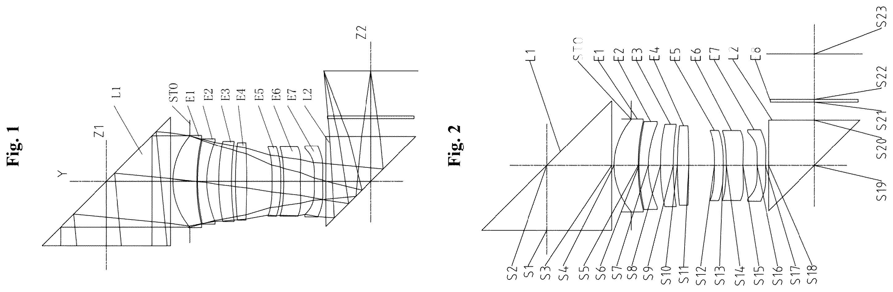
An optical imaging system according to Embodiment 1 of the disclosure will be described below with reference to D and A . shows a structural schematic diagram of an optical imaging system according to Embodiment 1 of the disclosure.
As shown in , the optical imaging system sequentially includes from an object side to an image side along a second optical axis: a first prism L 1 , a diaphragm STO, a first lens E 1 , a second lens E 2 , a third lens E 3 , a fourth lens E 4 , a fifth lens E 5 , a sixth lens E 6 , a seventh lens E 7 , a second prism L 2 and an optical filter E 8 . The first prism L 1 is a first refraction optical element in a first imaging lens group, the second prism L 2 is a second refraction optical element in a second imaging lens group.
The first prism L 1 includes an incidence surface S 1 , a reflecting surface S 2 and an emergence surface S 3 . The first lens E 1 has a positive refractive power, an object-side surface S 4 thereof is a convex surface, and an image-side surface S 5 is a concave surface. The second lens E 2 has a negative refractive power, an object-side surface S 6 thereof is a convex surface, and an image-side surface S 7 is a concave surface. The third lens E 3 has a negative refractive power, an object-side surface S 8 thereof is a concave surface, and an image-side surface S 9 is a convex surface. The fourth lens E 4 has a positive refractive power, an object-side surface S 10 thereof is a convex surface, and an image-side surface S 11 is a concave surface. The fifth lens E 5 has a positive refractive power, an object-side surface S 12 thereof is a concave surface, and an image-side surface S 13 is a convex surface. The sixth lens E 6 has a negative refractive power, an object-side surface S 14 thereof is a concave surface, and an image-side surface S 15 is a convex surface. The seventh lens E 7 has a negative refractive power, an object-side surface S 16 thereof is a convex surface, and an image-side surface S 17 is a concave surface. The second prism L 2 includes an incidence surface S 18 , a reflecting surface S 19 , and an emergence surface S 20 . The optical filter E 8 has an object-side surface S 21 and an image-side surface S 22 . The optical imaging system has an imaging surface S 23 . Light from an object penetrates through the incidence surface S 1 of the first prism L 1 along a first optical axis, sequentially penetrates through each of the surfaces S 3 to S 18 after deflected by the reflecting surface S 2 of the first prism L 1 to be along the second optical axis, then sequentially penetrates through each of the surfaces S 20 to S 21 after deflected by the reflecting surface S 19 of the second prism L 2 to be along a third optical axis, and is finally imaged on the imaging surface S 23 .
Table 1 shows a basic parameter table of the optical imaging system of Embodiment 1, wherein the units of the curvature radius, the thickness/distance and the focal length are all millimeters (mm).
TABLE 1
Material
Surface Surface Curvature Thickness/ Refractive Abbe Focal Conic
number type radius distance index number length coefficient
OBJ Spherical Infinite Infinite
S1 Spherical Infinite 5.0000 1.52 64.2
S2 Spherical Infinite 5.0000 1.52 64.2
S3 Spherical Infinite 1.5000
STO Spherical Infinite −1.3103
S4 Aspheric 5.4864 1.8593 1.55 56.1 12.60 0.0034
S5 Aspheric 23.8413 0.0601 2.3325
S6 Aspheric 13.5335 0.7129 1.67 19.2 −23.25 0.6333
S7 Aspheric 7.1225 0.9366 −0.0343
S8 Aspheric 24.9984 0.9869 1.55 56.1 −347.97 −0.8101
S9 Aspheric 21.7831 0.3105 4.2142
S10 Aspheric 26.6121 0.8786 1.55 56.1 28.91 −7.6150
S11 Spherical −38.3380 1.9729 −99.0000
S12 Spherical −51.8353 0.6819 1.67 19.2 61.00 8.9996
S13 Spherical −23.1054 0.2352 19.6206
S14 Aspheric 13.5765 1.2812 1.55 56.1 −17.81 −2.4573
S15 Aspheric 35.3763 1.0889 93.2392
S16 Aspheric 53.9753 0.6480 1.55 56.1 −46.69 −20.8085
S17 Aspheric 17.2384 0.2466 −61.2236
S18 Spherical Infinite 3.5000 1.52 64.2
S19 Spherical Infinite 3.5000 1.52 64.2
S20 Spherical Infinite 1.3882
S21 Spherical Infinite 0.2100 1.52 64.2
S22 Spherical Infinite 3.4911
S23 Spherical Infinite
In Embodiment 1, a value of a total effective focal length f of the optical imaging system is 24.90 mm. TTLz is an on-axis distance from the object-side surface S 1 of the first prism L 1 to the imaging surface S 23 on the first optical axis (or a normal direction of the imaging surface S 23 ), and a value of TTLz is 13.59 mm. ImgH is a half of a diagonal length of an effective pixel region on the imaging surface S 23 , and a value of ImgH is 3.65 mm. FOV is a maximum field of view, and a value of FOV is 16.7°.
In Embodiment 1, both the object-side surface and the image-side surface of any lens in the first lens E 1 to the seventh lens E 7 are aspheric surfaces, and a surface type x of each aspheric lens may be defined through but not limited to, the following aspheric surface formula:
x = ch 2 1 + 1 - ( k + 1 ) c 2 h 2 + ∑ Aih i , ( 1 )
wherein x is a distance vector height from a vertex of the aspheric surface when the aspheric surface is at a height of h along the optical axis direction; c is a paraxial curvature of the aspheric surface, c=1/R (namely, the paraxial curvature c is a reciprocal of the curvature radius R in Table 1 above); k is a conic coefficient; and Ai is a correction coefficient of the i-th order of the aspheric surface. Table 2 shows high-order coefficients A4, A6, A8, A10, A12, A14, A16, A18 and A20 that can be used for each of the aspheric mirror surfaces S 4 to S 17 in Embodiment 1.
TABLE 2
Surface
number A4 A6 A8 A10 A12 A14 A16 A18 A20
S4 −1.1861E−02 7.7705E−03 −6.6749E−04 1.8243E−04 1.1754E−04 1.4394E−06 2.4694E−05 −2.5345E−06 −1.4287E−07
S5 −1.5219E−01 2.2492E−02 −5.1892E−03 1.9543E−03 2.5537E−04 4.6528E−04 1.5384E−04 1.9590E−04 2.2980E−05
S6 4.8926E−02 −4.0554E−03 −2.0266E−04 6.9919E−04 7.6382E−05 6.0410E−04 5.3238E−06 2.3865E−04 −4.9899E−07
S7 7.9294E−02 4.9971E−03 −3.2761E−04 2.8785E−04 4.5860E−05 2.9193E−04 −1.5919E−04 7.5034E−05 −1.4106E−05
S8 −1.4971E−01 2.1576E−02 −4.3995E−03 3.1183E−03 8.1852E−05 −1.3421E−04 −1.9384E−04 −4.9398E−05 −1.3694E−05
S9 1.7348E−02 −1.0710E−02 5.7220E−03 −4.7958E−04 6.5289E−04 −6.2545E−04 −1.3327E−04 −2.5065E−04 −9.7488E−05
S10 1.3291E−02 −6.5059E−03 1.6472E−03 −1.5786E−03 1.2557E−03 8.7197E−05 8.6138E−05 −2.6093E−04 −1.4986E−04
S11 −5.4383E−02 2.0826E−02 −4.7158E−03 1.9247E−03 3.4401E−04 4.4098E−04 6.9352E−05 −7.6997E−05 −6.2396E−05
S12 2.3716E−01 −1.0775E−02 4.4549E−03 3.4547E−03 −6.0281E−04 4.9032E−04 3.9764E−05 −3.7139E−06 −1.8888E−05
S13 1.8869E−01 −1.8208E−02 3.1344E−03 2.9688E−03 −6.0415E−04 6.3004E−04 1.3454E−04 2.8498E−05 −5.1316E−05
S14 6.5010E−03 3.0237E−02 −8.3535E−03 1.0017E−03 2.9278E−05 7.5919E−05 3.1750E−04 1.0655E−04 −2.3563E−05
S15 2.5666E−01 4.3554E−02 −7.0824E−03 −4.4200E−04 −5.9752E−04 −3.4489E−04 1.9843E−04 3.7821E−05 −1.0416E−05
S16 7.9437E−01 −2.2172E−02 −5.0804E−03 −3.6383E−03 −1.6875E−03 −4.2371E−04 1.3572E−04 8.7842E−05 6.8500E−06
S17 5.9105E−01 −5.8089E−02 −5.0511E−04 −1.9611E−03 −8.0377E−04 −2.3974E−04 −4.1964E−05 −4.1088E−05 −2.0416E−05
A shows a longitudinal aberration curve of the optical imaging system according to Embodiment 1 to represent deviations of a convergence focal point after light with different wavelengths passes through the lens. B shows an astigmatism curve of the optical imaging system according to Embodiment 1 to represent a tangential image surface curvature and a sagittal image surface curvature. C shows a distortion curve of the optical imaging system according to Embodiment 1 to represent distortion values corresponding to different image heights. D shows a lateral color curve of the optical imaging system according to Embodiment 1 to represent deviations of different image heights on the imaging surface after the light passes through the lens. A shows a MTF curve of the optical imaging system according to Embodiment 1 to represent variations of a modulation degree with a spatial frequency. According to A- 3 D and A , it can be seen that the optical imaging system provided in Embodiment 1 may achieve high imaging quality.
Embodiment 2
An optical imaging system according to Embodiment 2 of the disclosure will be described below with reference to D . In the embodiment and the following embodiments, parts of descriptions similar to those about Embodiment 1 are omitted for simplicity. shows a structural schematic diagram of an optical imaging system according to Embodiment 2 of the disclosure.
As shown in , the optical imaging system sequentially includes from an object side to an image side along a second optical axis: a first prism L 1 , a diaphragm STO, a first lens E 1 , a second lens E 2 , a third lens E 3 , a fourth lens E 4 , a fifth lens E 5 , a sixth lens E 6 , a seventh lens E 7 , a second prism L 2 and an optical filter E 8 . The first prism L 1 is a first refraction optical element in a first imaging lens group, the second prism L 2 is a second refraction optical element in a second imaging lens group.
The first prism L 1 includes an incidence surface S 1 , a reflecting surface S 2 and an emergence surface S 3 . The first lens E 1 has a positive refractive power, an object-side surface S 4 thereof is a convex surface, and an image-side surface S 5 is a convex surface. The second lens E 2 has a negative refractive power, an object-side surface S 6 thereof is a convex surface, and an image-side surface S 7 is a concave surface. The third lens E 3 has a negative refractive power, an object-side surface S 8 thereof is a convex surface, and an image-side surface S 9 is a concave surface. The fourth lens E 4 has a positive refractive power, an object-side surface S 10 thereof is a convex surface, and an image-side surface S 11 is a convex surface. The fifth lens E 5 has a positive refractive power, an object-side surface S 12 thereof is a convex surface, and an image-side surface S 13 is a concave surface. The sixth lens E 6 has a negative refractive power, an object-side surface S 14 thereof is a concave surface, and an image-side surface S 15 is a concave surface. The seventh lens E 7 has a negative refractive power, an object-side surface S 16 thereof is a convex surface, and an image-side surface S 17 is a concave surface. The second prism L 2 includes an incidence surface S 18 , a reflecting surface S 19 and an emergence surface S 20 . The optical filter E 8 has an object-side surface S 21 and an image-side surface S 22 . The optical imaging system has an imaging surface S 23 . Light from an object penetrates through the incidence surface S 1 of the first prism L 1 along a first optical axis, sequentially penetrates through each of the surfaces S 3 to S 18 after deflected by the reflecting surface S 2 of the first prism L 1 to be along the second optical axis, then sequentially penetrates through each of the surfaces S 20 to S 21 after deflected by the reflecting surface S 19 of the second prism L 2 to be along a third optical axis, and is finally imaged on the imaging surface S 23 .
In Embodiment 2, a value of a total effective focal length f of the optical imaging system is 24.90 mm. TTLz is an on-axis distance from the object-side surface S 1 of the first prism L 1 to the imaging surface S 23 on the first optical axis (or a normal direction of the imaging surface S 23 ), and a value of TTLz is 13.93 mm. ImgH is a half of a diagonal length of an effective pixel region on the imaging surface S 23 , and a value of ImigH is 3.65 mm. FOV is a maximum field of view, and a value of FOV is 16.7°.
Table 3 shows a basic parameter table of the optical imaging system of Embodiment 2, wherein the units of the curvature radius, the thickness/distance and the focal length are all millimeters (mm). Table 4 shows high-order coefficients that can be used for each aspheric mirror surface in Embodiment 2. A surface type of each aspheric surface may be defined by formula (1) given in Embodiment 1.
TABLE 3
Material
Surface Surface Curvature Thickness/ Refractive Abbe Focal Conic
number type radius distance index number length coefficient
OBJ Spherical Infinite Infinite
S1 Spherical Infinite 5.0000 1.52 64.2
S2 Spherical Infinite 5.0000 1.52 64.2
S3 Spherical Infinite 1.5000
STO Spherical Infinite −1.0997
S4 Aspheric 6.2462 2.1043 1.55 56.1 10.85 −0.0390
S5 Aspheric −100.0000 0.2226 −88.7111
S6 Aspheric 19.2956 0.8943 1.67 19.2 −22.69 0.5222
S7 Aspheric 8.3930 0.4257 −0.0673
S8 Aspheric 267.9564 1.2725 1.55 56.1 −30.51 99.0000
S9 Aspheric 15.6531 0.3587 1.7181
S10 Aspheric 20.5609 1.3766 1.55 56.1 27.24 −1.1511
S11 Spherical −52.4299 1.5953 −91.5244
S12 Spherical 37.3638 0.6117 1.67 19.2 64.78 97.3065
S13 Spherical 250.7841 0.2270 99.0000
S14 Aspheric −21.5715 1.3038 1.55 56.1 −22.16 −27.0472
S15 Aspheric 28.1194 0.7982 89.3853
S16 Aspheric 13.7641 0.7815 1.55 56.1 −55.67 3.6304
S17 Aspheric 9.2835 0.1075 −26.7838
S18 Spherical Infinite 3.5000 1.52 64.2
S19 Spherical Infinite 3.5000 1.52 64.2
S20 Spherical Infinite 1.5837
S21 Spherical Infinite 0.2100 1.52 64.2
S22 Spherical Infinite 3.6865
S23 Spherical Infinite
TABLE 4
Surface
number A4 A6 A8 A10 A12 A14 A16 A18 A20
S4 −4.4479E−03 6.6523E−03 1.9914E−04 9.3993E−05 5.6736E−05 1.9098E−05 8.2671E−06 −8.3695E−06 −1.9458E−06
S5 −1.5279E−01 2.2576E−02 −4.4710E−03 1.4494E−03 −2.6984E−04 2.2188E−04 −1.3250E−04 2.7785E−05 2.6326E−05
S6 4.7042E−02 −5.1561E−03 −6.9230E−04 8.1456E−04 −4.4227E−04 3.3532E−04 −1.6706E−04 9.3859E−05 3.2154E−05
S7 7.9115E−02 −6.1501E−03 −6.2178E−04 4.9732E−04 −5.0870E−04 2.0998E−04 −2.2356E−04 2.6087E−05 −4.7546E−06
S8 −1.5812E−01 1.8931E−02 −5.5798E−03 2.1212E−03 −4.8281E−04 1.0080E−04 −2.5892E−04 −7.8801E−05 −1.8545E−05
S9 2.1856E−02 −1.0526E−02 3.1672E−03 4.0479E−04 8.5066E−04 4.9108E−06 −3.2324E−04 −1.7389E−04 −7.4477E−07
S10 9.1905E−03 −6.6508E−03 3.0994E−03 −1.5449E−03 1.7372E−03 3.0043E−04 −9.1598E−05 −1.0268E−04 −3.8193E−06
S11 −5.7140E−02 1.9040E−02 −2.7562E−03 −3.8183E−04 7.4772E−04 1.9504E−05 4.2407E−06 −3.6088E−05 −1.3976E−05
S12 2.4151E−01 −8.1241E−03 4.4025E−03 2.0674E−03 −2.2459E−04 −2.3941E−04 7.6563E−05 −6.6365E−05 −3.2828E−05
S13 2.0546E−01 −1.6134E−02 4.6732E−03 2.1199E−03 5.2868E−05 2.0935E−05 1.9475E−04 −5.6526E−05 −5.6795E−05
S14 −1.1943E−02 2.9705E−02 −8.1891E−03 9.2250E−04 9.0718E−04 3.1498E−04 1.1367E−04 5.5133E−05 −4.3784E−05
S15 2.6462E−01 4.6091E−02 −4.8475E−03 −1.0760E−04 1.2566E−05 −3.4681E−04 −1.0686E−04 9.5845E−05 −9.7294E−06
S16 8.0485E−01 −1.5854E−02 1.2923E−03 −1.5283E−03 −7.9949E−04 −5.0478E−04 −1.6714E−04 6.6912E−05 8.9439E−06
S17 5.4060E−01 −4.7529E−02 2.2370E−03 −9.9154E−04 −4.4469E−04 −2.0193E−04 −5.4521E−05 1.9936E−06 −2.7357E−05
A shows a longitudinal aberration curve of the optical imaging system according to Embodiment 2 to represent deviations of a convergence focal point after light with different wavelengths passes through the lens. B shows an astigmatism curve of the optical imaging system according to Embodiment 2 to represent a tangential image surface curvature and a sagittal image surface curvature. C shows a distortion curve of the optical imaging system according to Embodiment 2 to represent distortion values corresponding to different image heights. D shows a lateral color curve of the optical imaging system according to Embodiment 2 to represent deviations of different image heights on the imaging surface after the light passes through the lens. B shows a MTF curve of the optical imaging system according to Embodiment 2 to represent variations of a modulation degree with a spatial frequency. According to A- 5 D and B , it can be seen that the optical imaging system provided in Embodiment 2 may achieve high imaging quality.
Embodiment 3
An optical imaging system according to Embodiment 3 of the disclosure will be described below with reference to D . shows a structural schematic diagram of an optical imaging system according to Embodiment 3 of the disclosure.
As shown in , the optical imaging system sequentially includes from an object side to an image side along a second optical axis, a first prism L 1 , a diaphragm STO, a first lens E 1 , a second lens E 2 , a third lens E 3 , a fourth lens E 4 , a fifth lens E 5 , a sixth lens E 6 , a seventh lens E 7 , a second prism L 2 and an optical filter E 8 . The first prism L 1 is a first refraction optical element in a first imaging lens group, the second prism L 2 is a second refraction optical element in a second imaging lens group.
The first prism L 1 includes an incidence surface S 1 , a reflecting surface S 2 and an emergence surface S 3 . The first lens E 1 has a positive refractive power, an object-side surface S 4 thereof is a convex surface, and an image-side surface S 5 is a concave surface. The second lens E 2 has a negative refractive power, an object-side surface S 6 thereof is a convex surface, and an image-side surface S 7 is a concave surface. The third lens E 3 has a negative refractive power, an object-side surface S 8 thereof is a concave surface, and an image-side surface S 9 is a concave surface. The fourth lens E 4 has a positive refractive power, an object-side surface S 10 thereof is a convex surface, and an image-side surface S 11 is a convex surface. The fifth lens E 5 has a positive refractive power, an object-side surface S 12 thereof is a convex surface, and an image-side surface S 13 is a convex surface. The sixth lens E 6 has a negative refractive power, an object-side surface S 14 thereof is a concave surface, and an image-side surface S 15 is a concave surface. The seventh lens E 7 has a negative refractive power, an object-side surface S 16 thereof is a convex surface, and an image-side surface S 17 is a concave surface. The second prism L 2 includes an incidence surface S 18 , a reflecting surface S 19 and an emergence surface S 20 . The optical filter E 8 has an object-side surface S 21 and an image-side surface S 22 . The optical imaging system has an imaging surface S 23 . Light from an object penetrates through the incidence surface S 1 of the first prism L 1 along a first optical axis, sequentially penetrates through each of the surfaces S 3 to S 18 after deflected by the reflecting surface S 2 of the first prism L 1 to be along the second optical axis, then sequentially penetrates through each of the surfaces S 20 to S 21 after deflected by the reflecting surface S 19 of the second prism L 2 to be along a third optical axis, and is finally imaged on the imaging surface S 23 .
In Embodiment 3, a value of a total effective focal length f of the optical imaging system is 24.90 mm. TTLz is an on-axis distance from the object-side surface S 1 of the first prism L 1 to the imaging surface S 23 on the first optical axis (or a normal direction of the imaging surface S 23 ), and a value of TTLz is 13.93 mm. ImgH is a half of a diagonal length of an effective pixel region on the imaging surface S 23 , and a value of ImigH is 3.65 mm. FOV is a maximum field of view, and a value of FOV is 16.7°.
Table 5 shows a basic parameter table of the optical imaging system of Embodiment 3, wherein the units of the curvature radius, the thickness/distance and the focal length are all millimeters (mm). Table 6 shows high-order coefficients that can be used for each aspheric mirror surface in Embodiment 3. A surface type of each aspheric surface may be defined by formula (1) given in Embodiment 1.
TABLE 5
Material
Surface Surface Curvature Thickness/ Refractive Abbe Focal Conic
number type radius distance index number length coefficient
OBJ Spherical Infinite Infinite
S1 Spherical Infinite 5.0000 1.52 64.2
S2 Spherical Infinite 5.0000 1.52 64.2
S3 Spherical Infinite 1.5000
STO Spherical Infinite −1.2587
S4 Aspheric 5.6423 1.9073 1.55 56.1 11.71 −0.0038
S5 Aspheric 42.3054 0.0398 2.2933
S6 Aspheric 17.0934 0.7396 1.67 19.2 −25.54 0.6854
S7 Aspheric 8.4455 0.7831 −0.0655
S8 Aspheric −213.7609 1.1536 1.55 56.1 −20.80 −99.0000
S9 Aspheric 12.0123 0.4339 0.4846
S10 Aspheric 13.1025 1.0717 1.55 56.1 14.68 3.1574
S11 Spherical −20.0450 1.8304 −90.6814
S12 Spherical 194.7918 0.8080 1.67 19.2 96.83 99.0000
S13 Spherical −98.6311 0.2325 99.0000
S14 Aspheric −16.5037 1.3389 1.55 56.1 −18.61 −15.0526
S15 Aspheric 27.1734 1.0537 79.1019
S16 Aspheric 20.1482 0.6713 1.55 56.1 −56.83 26.1605
S17 Aspheric 12.0712 0.0879 −31.8813
S18 Spherical Infinite 3.5000 1.52 64.2
S19 Spherical Infinite 3.5000 1.52 64.2
S20 Spherical Infinite 1.5401
S21 Spherical Infinite 0.2100 1.52 64.2
S22 Spherical Infinite 3.6430
S23 Spherical Infinite
TABLE 6
Surface
number A4 A6 A8 A10 A12 A14 A16 A18 A20
S4 −1.0533E−02 8.0936E−03 2.8452E−04 2.7234E−04 1.1232E−04 1.2236E−05 4.0008E−07 −4.5868E−06 −1.3779E−06
S5 −1.5146E−01 2.3260E−02 −3.9621E−03 1.5465E−03 1.4365E−04 2.0407E−04 1.0889E−04 9.5772E−05 1.2158E−05
S6 4.8770E−02 −4.8519E−03 −3.6228E−04 6.5844E−04 1.0531E−04 3.4923E−04 1.1010E−04 9.5163E−05 1.8585E−06
S7 8.0049E−02 −4.5063E−03 −5.9864E−04 5.4798E−04 3.3983E−05 2.1761E−04 −3.8000E−05 −3.4531E−05 −1.5351E−05
S8 −1.5202E−01 2.0561E−02 −4.9255E−03 2.5358E−03 −1.8272E−04 9.4350E−05 −1.7545E−04 −6.3602E−05 3.6828E−06
S9 1.8850E−02 −1.1533E−02 4.5183E−03 −3.3775E−05 5.1139E−04 −3.2325E−04 −5.0320E−04 1.6234E−05 5.1048E−05
S10 1.2769E−02 −4.5716E−03 1.5381E−03 −1.7743E−03 1.8154E−03 3.8183E−04 −3.1249E−04 −3.3149E−05 2.5148E−06
S11 −5.3922E−02 1.7817E−02 −3.4596E−03 7.8672E−04 1.0943E−03 3.2926E−05 −2.7528E−04 −8.3531E−05 −2.6359E−05
S12 2.2939E−01 −7.0984E−03 3.3434E−03 2.0413E−03 −4.4504E−04 3.0353E−05 1.0458E−05 −2.9921E−05 −1.2033E−05
S13 1.9467E−01 −1.6303E−02 2.4314E−03 1.4922E−03 −3.5776E−04 1.8117E−04 1.1283E−04 −4.3391E−05 −9.8845E−06
S14 −1.1771E−02 3.2350E−02 −8.7073E−03 1.1495E−03 4.1511E−04 1.0000E−04 1.1472E−04 −2.3035E−05 −2.4970E−06
S15 2.5786E−01 4.7390E−02 −7.2858E−03 1.1428E−03 1.2249E−04 −2.7458E−04 3.9042E−06 3.2271E−05 −2.3930E−07
S16 7.8572E−01 −2.0968E−02 −3.1069E−03 −3.1657E−04 −4.7391E−04 −4.0203E−04 −5.7873E−05 5.9883E−05 1.0532E−05
S17 5.6277E−01 −5.8825E−02 6.6080E−04 −2.2396E−04 −4.7388E−04 −1.9634E−04 −2.8531E−06 1.0193E−05 −1.6506E−05
A shows a longitudinal aberration curve of the optical imaging system according to Embodiment 3 to represent deviations of a convergence focal point after light with different wavelengths passes through the lens. B shows an astigmatism curve of the optical imaging system according to Embodiment 3 to represent a tangential image surface curvature and a sagittal image surface curvature. C shows a distortion curve of the optical imaging system according to Embodiment 3 to represent distortion values corresponding to different image heights. D shows a lateral color curve of the optical imaging system according to Embodiment 3 to represent deviations of different image heights on the imaging surface after the light passes through the lens. C shows a MTF curve of the optical imaging system according to Embodiment 3 to represent variations of a modulation degree with a spatial frequency. According to A- 7 D and C , it can be seen that the optical imaging system provided in Embodiment 3 may achieve high imaging quality.
Embodiment 4
An optical imaging system according to Embodiment 4 of the disclosure will be described below with reference to D . shows a structural schematic diagram of an optical imaging system according to Embodiment 4 of the disclosure.
As shown in , the optical imaging system sequentially includes from an object side to an image side along a second optical axis, a first prism L 1 , a diaphragm STO, a first lens E 1 , a second lens E 2 , a third lens E 3 , a fourth lens E 4 , a fifth lens E 5 , a sixth lens E 6 , a seventh lens E 7 , a second prism L 2 and an optical filter E 8 . The first prism L 1 is a first refraction optical element in a first imaging lens group, the second prism L 2 is a second refraction optical element in a second imaging lens group.
The first prism L 1 includes an incidence surface S 1 , a reflecting surface S 2 and an emergence surface S 3 . The first lens E 1 has a positive refractive power, an object-side surface S 4 thereof is a convex surface, and an image-side surface S 5 is a concave surface. The second lens E 2 has a negative refractive power, an object-side surface S 6 thereof is a convex surface, and an image-side surface S 7 is a concave surface. The third lens E 3 has a negative refractive power, an object-side surface S 8 thereof is a convex surface, and an image-side surface S 9 is a concave surface. The fourth lens E 4 has a positive refractive power, an object-side surface S 10 thereof is a convex surface, and an image-side surface S 11 is a concave surface. The fifth lens E 5 has a positive refractive power, an object-side surface S 12 thereof is a convex surface, and an image-side surface S 13 is a convex surface. The sixth lens E 6 has a negative refractive power, an object-side surface S 14 thereof is a concave surface, and an image-side surface S 15 is a concave surface. The seventh lens E 7 has a negative refractive power, an object-side surface S 16 thereof is a convex surface, and an image-side surface S 17 is a concave surface. The second prism L 2 includes an incidence surface S 18 , a reflecting surface S 19 and an emergence surface S 20 . The optical filter E 8 has an object-side surface S 21 and an image-side surface S 22 . The optical imaging system has an imaging surface S 23 . Light from an object penetrates through the incidence surface S 1 of the first prism L 1 along a first optical axis, sequentially penetrates through each of the surfaces S 3 to S 18 after deflected by the reflecting surface S 2 of the first prism L 1 to be along the second optical axis, then sequentially penetrates through each of the surfaces S 20 to S 21 after deflected by the reflecting surface S 19 of the second prism L 2 to be along a third optical axis, and is finally imaged on the imaging surface S 23 .
In Embodiment 4, a value of a total effective focal length f of the optical imaging system is 24.90 mm. TTLz is an on-axis distance from the object-side surface S 1 of the first prism L 1 to the imaging surface S 23 on the first optical axis (or a normal direction of the imaging surface S 23 ), and a value of TTLz is 13.73 mm. ImgH is a half of a diagonal length of an effective pixel region on the imaging surface S 23 , and a value of ImgH is 3.65 mm. FOV is a maximum field of view, and a value of FOV is 16.7°.
Table 7 shows a basic parameter table of the optical imaging system of Embodiment 4, wherein the units of the curvature radius, the thickness/distance and the focal length are all millimeters (mm). Table 8 shows high-order coefficients that can be used for each aspheric mirror surface in Embodiment 4. A surface type of each aspheric surface may be defined by formula (1) given in Embodiment 1.
TABLE 7
Material
Surface Surface Curvature Thickness/ Refractive Abbe Focal Conic
number type radius distance index number length coefficient
OBJ Spherical Infinite Infinite
S1 Spherical Infinite 5.0000 1.52 64.2
S2 Spherical Infinite 5.0000 1.52 64.2
S3 Spherical Infinite 1.5000
STO Spherical Infinite −1.2653
S4 Aspheric 5.6302 1.9045 1.55 56.1 12.86 0.0009
S5 Aspheric 25.0368 0.0746 0.8644
S6 Aspheric 13.1668 0.7288 1.67 19.2 −23.68 0.5697
S7 Aspheric 7.0674 0.8236 −0.0238
S8 Aspheric 25.0455 1.1662 1.55 56.1 −229.70 0.4141
S9 Aspheric 20.5325 0.3558 4.6332
S10 Aspheric 16.7680 1.0843 1.55 56.1 32.01 −8.7791
S11 Spherical 404.7020 1.8472 −99.0000
S12 Spherical 787.0915 0.6674 1.67 19.2 64.51 99.0000
S13 Spherical −46.2174 0.1964 50.2863
S14 Aspheric −17.2058 1.3844 1.55 56.1 −19.70 −9.1800
S15 Aspheric 29.5035 0.9821 87.0784
S16 Aspheric 18.9704 0.7018 1.55 56.1 −51.79 0.9774
S17 Aspheric 11.2045 0.0912 −35.2756
S18 Spherical Infinite 3.5000 1.52 64.2
S19 Spherical Infinite 3.5000 1.52 64.2
S20 Spherical Infinite 1.4650
S21 Spherical Infinite 0.2100 1.52 64.2
S22 Spherical Infinite 3.5679
S23 Spherical Infinite
TABLE 8
Surface
number A4 A6 A8 A10 A12 A14 A16 A18 A20
S4 −1.1377E−02 7.6812E−03 3.8789E−05 1.6887E−04 1.3015E−04 9.4929E−06 9.8880E−06 −2.2743E−06 −3.7025E−07
S5 −1.5041E−01 2.3145E−02 −3.9707E−03 1.7446E−03 3.2533E−04 3.2226E−04 1.2483E−04 1.5277E−04 3.3466E−05
S6 4.9487E−02 −4.6519E−03 −3.2651E−04 8.7620E−04 4.9340E−05 4.6610E−04 5.0183E−05 1.7781E−04 1.9377E−05
S7 7.8777E−02 −4.8108E−03 −3.5445E−04 7.4373E−04 −1.8322E−05 2.7305E−04 −9.9288E−05 4.4664E−05 −1.2131E−05
S8 −1.5077E−01 2.0662E−02 −4.5548E−03 3.1375E−03 −5.9557E−06 −6.8678E−05 −2.4924E−04 −6.6549E−05 −2.1772E−05
S9 1.6792E−02 −1.0869E−02 4.6913E−03 5.2173E−04 4.7307E−04 −4.9056E−04 −6.4708E−04 −2.2452E−04 −4.7379E−05
S10 1.4091E−02 −6.3823E−03 2.0936E−03 −1.9296E−03 1.8263E−03 4.4877E−04 −2.4851E−04 −1.2188E−04 −4.1743E−05
S11 −5.6975E−02 2.1166E−02 −4.0659E−03 6.7291E−04 1.3315E−03 3.1417E−04 −1.2242E−04 −7.2935E−05 −2.9255E−05
S12 2.3117E−01 −9.0349E−03 4.2331E−03 2.3475E−03 −5.0548E−04 7.4461E−05 1.6046E−05 −2.7754E−05 −1.7913E−05
S13 1.9401E−01 −1.6019E−02 2.9696E−03 2.1166E−03 −4.4891E−04 2.6113E−04 8.8037E−05 1.5204E−06 −3.2895E−05
S14 −2.1175E−03 3.0274E−02 −8.5623E−03 1.1243E−03 5.3286E−04 1.8975E−04 9.0700E−05 5.2757E−05 −2.1703E−05
S15 2.5744E−01 4.5088E−02 −6.6827E−03 5.5648E−04 1.6592E−04 −3.1838E−04 −5.6013E−06 5.6457E−05 −5.7699E−06
S16 7.9212E−01 −1.7557E−02 −2.3220E−03 −1.4104E−03 −7.0831E−04 −4.7893E−04 −8.8933E−05 6.6329E−05 9.5352E−06
S17 5.7081E−01 −5.3792E−02 5.1591E−04 −8.9033E−04 −5.3121E−04 −2.5183E−04 −4.3097E−05 −3.1702E−06 −2.4135E−05
A shows a longitudinal aberration curve of the optical imaging system according to Embodiment 4 to represent deviations of a convergence focal point after light with different wavelengths passes through the lens. B shows an astigmatism curve of the optical imaging system according to Embodiment 4 to represent a tangential image surface curvature and a sagittal image surface curvature. C shows a distortion curve of the optical imaging system according to Embodiment 4 to represent distortion values corresponding to different image heights. D shows a lateral color curve of the optical imaging system according to Embodiment 4 to represent deviations of different image heights on the imaging surface after the light passes through the lens. D shows a MTF curve of the optical imaging system according to Embodiment 4 to represent variations of a modulation degree with a spatial frequency. According to A- 9 D and D , it can be seen that the optical imaging system provided in Embodiment 4 may achieve high imaging quality.
Embodiment 5
An optical imaging system according to Embodiment 5 of the disclosure will be described below with reference to D . shows a structural schematic diagram of an optical imaging system according to Embodiment 5 of the disclosure.
As shown in , the optical imaging system sequentially includes from an object side to an image side along a second optical axis: a first prism L 1 , a diaphragm STO, a first lens E 1 , a second lens E 2 , a third lens E 3 , a fourth lens E 4 , a fifth lens E 5 , a sixth lens E 6 , a seventh lens E 7 , a second prism L 2 and an optical filter E 8 . The first prism L 1 is a first refraction optical element in a first imaging lens group, the second prism L 2 is a second refraction optical element in a second imaging lens group.
The first prism L 1 includes an incidence surface S 1 , a reflecting surface S 2 and an emergence surface S 3 . The first lens E 1 has a positive refractive power, an object-side surface S 4 thereof is a convex surface, and an image-side surface S 5 is a concave surface. The second lens E 2 has a negative refractive power, an object-side surface S 6 thereof is a convex surface, and an image-side surface S 7 is a concave surface. The third lens E 3 has a negative refractive power, an object-side surface S 8 thereof is a convex surface, and an image-side surface S 9 is a concave surface. The fourth lens E 4 has a positive refractive power, an object-side surface S 10 thereof is a convex surface, and an image-side surface S 11 is a convex surface. The fifth lens E 5 has a positive refractive power, an object-side surface S 12 thereof is a concave surface, and an image-side surface S 13 is a convex surface. The sixth lens E 6 has a negative refractive power, an object-side surface S 14 thereof is a concave surface, and an image-side surface S 15 is a convex surface. The seventh lens E 7 has a negative refractive power, an object-side surface S 16 thereof is a convex surface, and an image-side surface S 17 is a concave surface. The second prism L 2 includes an incidence surface S 18 , a reflecting surface S 19 and an emergence surface S 20 . The optical filter E 8 has an object-side surface S 21 and an image-side surface S 22 . The optical imaging system has an imaging surface S 23 . Light from an object penetrates through the incidence surface S 1 of the first prism L 1 along a first optical axis, sequentially penetrates through each of the surfaces S 3 to S 18 after deflected by the reflecting surface S 2 of the first prism L 1 to be along the second optical axis, then sequentially penetrates through each of the surfaces S 20 to S 21 after deflected by the reflecting surface S 19 of the second prism L 2 to be along a third optical axis, and is finally imaged on the imaging surface S 23 .
In Embodiment 5, a value of a total effective focal length f of the optical imaging system is 24.90 mm. TTLz is an on-axis distance from the object-side surface S 1 of the first prism L 1 to the imaging surface S 23 on the first optical axis (or a normal direction of the imaging surface S 23 ), and a value of TTLz is 13.56 mm. ImgH is a half of a diagonal length of an effective pixel region on the imaging surface S 23 , and a value of ImigH is 3.65 mm. FOV is a maximum field of view, and a value of FOV is 16.7°.
Table 9 shows a basic parameter table of the optical imaging system of Embodiment 5, wherein the units of the curvature radius, the thickness/distance and the focal length are all millimeters (mm). Table 10 shows high-order coefficients that can be used for each aspheric mirror surface in Embodiment 5. A surface type of each aspheric surface may be defined by formula (1) given in Embodiment 1.
TABLE 9
Material
Surface Surface Curvature Thickness/ Refractive Abbe Focal Conic
number type radius distance index number length coefficient
OBJ Spherical Infinite Infinite
S1 Spherical Infinite 5.0000 1.52 64.2
S2 Spherical Infinite 5.0000 1.52 64.2
S3 Spherical Infinite 1.5000
STO Spherical Infinite −1.2865
S4 Aspheric 5.5633 1.9045 1.55 56.1 12.54 0.0039
S5 Aspheric 26.1064 0.0951 1.1500
S6 Aspheric 13.5639 0.7429 1.67 19.2 −22.40 0.5662
S7 Aspheric 7.0014 0.7669 −0.0280
S8 Aspheric 20.9395 1.0930 1.55 56.1 −279.32 −0.2235
S9 Aspheric 18.0717 0.3057 4.3878
S10 Aspheric 17.5371 1.0371 1.55 56.1 31.29 −8.5956
S11 Spherical −639.3964 1.9227 99.0000
S12 Spherical −110.0866 0.6000 1.67 19.2 55.17 −39.1287
S13 Spherical −27.9465 0.2763 26.3420
S14 Aspheric −11.6742 1.1504 1.55 56.1 −23.05 −3.2105
S15 Aspheric −167.5057 1.0363 99.0000
S16 Aspheric 51.2873 0.7229 1.55 56.1 −31.03 80.2145
S17 Aspheric 12.6706 0.1828 −32.0946
S18 Spherical Infinite 3.5000 1.52 64.2
S19 Spherical Infinite 3.5000 1.52 64.2
S20 Spherical Infinite 1.3680
S21 Spherical Infinite 0.2100 1.52 64.2
S22 Spherical Infinite 3.4720
S23 Spherical Infinite
TABLE 10
Surface
number A4 A6 A8 A10 A12 A14 A16 A18 A20
S4 −1.1985E−02 7.5543E−03 9.4104E−06 1.8977E−04 1.0734E−04 1.9366E−05 2.0661E−05 2.6786E−07 −6.1647E−07
S5 −1.5084E−01 2.2979E−02 −4.1940E−03 1.6885E−03 2.9697E−04 3.4125E−04 1.3529E−04 1.6196E−04 2.2398E−07
S6 4.9501E−02 −4.5451E−03 −2.5353E−04 8.1598E−04 8.0043E−05 4.5871E−04 6.7377E−05 2.0108E−04 −6.6742E−06
S7 7.8931E−02 −4.6711E−03 −3.7457E−04 6.6087E−04 −2.7395E−05 2.7054E−04 −6.1740E−05 5.7489E−05 1.0262E−05
S8 −1.5031E−01 2.0624E−02 −4.8731E−03 3.0253E−03 7.1518E−06 −1.3488E−04 −2.4019E−04 −1.0913E−04 3.7804E−05
S9 1.7389E−02 −1.0656E−02 4.9348E−03 3.2026E−04 6.0061E−04 −5.5071E−04 −6.1585E−04 −2.6154E−04 4.3660E−05
S10 1.3423E−02 −6.2537E−03 2.0403E−03 −1.7642E−03 1.6511E−03 4.5896E−04 −2.4804E−04 −1.7150E−04 −2.5426E−05
S11 −5.5325E−02 1.9865E−02 −4.4512E−03 1.1506E−03 1.0986E−03 4.2955E−04 −1.5434E−04 −1.2183E−04 −5.9423E−05
S12 2.3402E−01 −8.1341E−03 4.1135E−03 2.8748E−03 −5.2254E−04 2.2893E−04 3.2217E−05 −5.1778E−05 −3.7000E−05
S13 1.9081E−01 −1.7044E−02 3.1732E−03 2.5321E−03 −3.6354E−04 4.0527E−04 1.3529E−04 −5.9572E−05 −5.7369E−05
S14 3.5022E−03 3.2419E−02 −8.1448E−03 1.1752E−03 5.6662E−04 1.2644E−04 1.7689E−04 2.8633E−05 −2.5020E−05
S15 2.4359E−01 4.4716E−02 −8.2843E−03 6.6008E−04 4.1425E−05 −3.1385E−04 5.7858E−05 4.8285E−05 −1.0252E−05
S16 7.8833E−01 −2.4530E−02 −3.3492E−03 −2.1340E−03 −1.0759E−03 −4.6844E−04 −2.3975E−05 7.3874E−05 5.7127E−06
S17 5.6355E−01 −6.0925E−02 1.9775E−03 −1.4994E−03 −6.1438E−04 −2.4491E−04 −4.2692E−05 −1.3744E−05 −2.2435E−05
A shows a longitudinal aberration curve of the optical imaging system according to Embodiment 5 to represent deviations of a convergence focal point after light with different wavelengths passes through the lens. B shows an astigmatism curve of the optical imaging system according to Embodiment 5 to represent a tangential image surface curvature and a sagittal image surface curvature. C shows a distortion curve of the optical imaging system according to Embodiment 5 to represent distortion values corresponding to different image heights. D shows a lateral color curve of the optical imaging system according to Embodiment 5 to represent deviations of different image heights on the imaging surface after the light passes through the lens. E shows a MTF curve of the optical imaging system according to Embodiment 5 to represent variations of a modulation degree with a spatial frequency. According to A- 11 D and E , it can be seen that the optical imaging system provided in Embodiment 5 may achieve high imaging quality.
Embodiment 6
An optical imaging system according to Embodiment 6 of the disclosure will be described below with reference to D . shows a structural schematic diagram of an optical imaging system according to Embodiment 6 of the disclosure.
As shown in , the optical imaging system sequentially includes from an object side to an image side along a second optical axis: a first prism L 1 , a diaphragm STO, a first lens E 1 , a second lens E 2 , a third lens E 3 , a fourth lens E 4 , a fifth lens E 5 , a sixth lens E 6 , a seventh lens E 7 , a second prism L 2 and an optical filter E 8 . The first prism L 1 is a first refraction optical element in a first imaging lens group, the second prism L 2 is a second refraction optical element in a second imaging lens group.
The first prism L 1 includes an incidence surface S 1 , a reflecting surface S 2 and an emergence surface S 3 . The first lens E 1 has a positive refractive power, an object-side surface S 4 thereof is a convex surface, and an image-side surface S 5 is a concave surface. The second lens E 2 has a negative refractive power, an object-side surface S 6 thereof is a convex surface, and an image-side surface S 7 is a concave surface. The third lens E 3 has a negative refractive power, an object-side surface S 8 thereof is a convex surface, and an image-side surface S 9 is a concave surface. The fourth lens E 4 has a positive refractive power, an object-side surface S 10 thereof is a convex surface, and an image-side surface S 11 is a convex surface. The fifth lens E 5 has a positive refractive power, an object-side surface S 12 thereof is a concave surface, and an image-side surface S 13 is a convex surface. The sixth lens E 6 has a negative refractive power, an object-side surface S 14 thereof is a concave surface, and an image-side surface S 15 is a concave surface. The seventh lens E 7 has a negative refractive power, an object-side surface S 16 thereof is a concave surface, and an image-side surface S 17 is a concave surface. The second prism L 2 includes an incidence surface S 18 , a reflecting surface S 19 and an emergence surface S 20 . The optical filter E 8 has an object-side surface S 21 and an image-side surface S 22 . The optical imaging system has an imaging surface S 23 . Light from an object penetrates through the incidence surface S 1 of the first prism L 1 along a first optical axis, sequentially penetrates through each of the surfaces S 3 to S 18 after deflected by the reflecting surface S 2 of the first prism L 1 to be along the second optical axis, then sequentially penetrates through each of the surfaces S 20 to S 21 after deflected by the reflecting surface S 19 of the second prism L 2 to be along a third optical axis, and is finally imaged on the imaging surface S 23 .
In Embodiment 6, a value of a total effective focal length f of the optical imaging system is 24.90 mm. TTLz is an on-axis distance from the object-side surface S 1 of the first prism L 1 to the imaging surface S 23 on the first optical axis (or a normal direction of the imaging surface S 23 ), and a value of TTLz is 13.59 mm. ImgH is a half of a diagonal length of an effective pixel region on the imaging surface S 23 , and a value of ImigH is 3.65 mm. FOV is a maximum field of view, and a value of FOV is 16.7°.
Table 11 shows a basic parameter table of the optical imaging system of Embodiment 6, wherein the units of the curvature radius, the thickness/distance and the focal length are all millimeters (mm). Table 12 shows high-order coefficients that can be used for each aspheric mirror surface in Embodiment 6. A surface type of each aspheric surface may be defined by formula (1) given in Embodiment 1.
TABLE 11
Material
Surface Surface Curvature Thickness/ Refractive Abbe Focal Conic
number type radius distance index number length coefficient
OBJ Spherical Infinite Infinite
S1 Spherical Infinite 5.0000 1.52 64.2
S2 Spherical Infinite 5.0000 1.52 64.2
S3 Spherical Infinite 1.5000
STO Spherical Infinite −1.2985
S4 Aspheric 5.5386 1.8839 1.55 56.1 12.62 0.0130
S5 Aspheric 24.9003 0.0920 1.3465
S6 Aspheric 13.6248 0.7037 1.67 19.2 −23.08 0.6289
S7 Aspheric 7.1259 0.9240 −0.0202
S8 Aspheric 22.3952 1.0174 1.55 56.1 −286.25 −1.5471
S9 Aspheric 19.2736 0.3974 5.5428
S10 Aspheric 19.9019 0.9205 1.55 56.1 31.12 −10.8318
S11 Spherical −114.1122 1.9698 −99.0000
S12 Spherical −122.6040 0.6490 1.67 19.2 57.73 −99.0000
S13 Spherical −29.6978 0.2017 24.7649
S14 Aspheric −15.6200 1.1987 1.55 56.1 −20.98 −1.2452
S15 Aspheric 44.0705 1.1649 94.0954
S16 Aspheric −500.0000 0.6859 1.55 56.1 −36.08 −99.0000
S17 Aspheric 20.5099 0.0696 −33.0396
S18 Spherical Infinite 3.5000 1.52 64.2
S19 Spherical Infinite 3.5000 1.52 64.2
S20 Spherical Infinite 1.3803
S21 Spherical Infinite 0.2100 1.52 64.2
S22 Spherical Infinite 3.4897
S23 Spherical Infinite
TABLE 12
Surface
number A4 A6 A8 A10 A12 A14 A16 A18 A20
S4 −1.4317E−02 7.4735E−03 −1.3987E−04 1.9954E−04 1.5160E−04 2.9709E−05 1.6811E−05 3.6151E−07 1.0669E−07
S5 −1.5102E−01 2.2640E−02 −4.1566E−03 1.7690E−03 3.8113E−04 4.0245E−04 1.7353E−04 1.7329E−04 1.9094E−05
S6 4.9011E−02 −4.5228E−03 −4.0677E−04 8.6595E−04 1.1443E−04 5.2401E−04 1.2509E−04 1.9341E−04 7.9763E−06
S7 7.8661E−02 −5.1458E−03 −4.9760E−04 5.6643E−04 2.9217E−05 2.8635E−04 −2.3809E−05 3.7640E−05 −5.1615E−06
S8 −1.4908E−01 2.1118E−02 −4.1865E−03 3.0970E−03 1.2995E−04 −2.0271E−04 −2.9708E−04 −1.4060E−04 −4.9490E−06
S9 1.5454E−02 −1.1106E−02 4.7042E−03 3.1000E−04 5.6948E−04 −6.5494E−04 −6.9639E−04 −3.5153E−04 −2.4464E−05
S10 1.5358E−02 −6.2115E−03 2.0719E−03 −1.6515E−03 1.7054E−03 4.2373E−04 −2.3312E−04 −2.3359E−04 −4.5781E−05
S11 −5.7510E−02 2.0689E−02 −3.7941E−03 1.0670E−03 1.0965E−03 3.9001E−04 −1.4927E−04 −1.4925E−04 −4.3710E−05
S12 2.3614E−01 −8.8496E−03 4.1107E−03 2.8145E−03 −5.1995E−04 2.2642E−04 −5.5285E−05 −9.1193E−05 −2.5436E−05
S13 1.9033E−01 −1.5534E−02 3.0941E−03 3.0384E−03 −3.1046E−04 5.4652E−04 4.5604E−05 −5.9774E−05 −2.9481E−05
S14 8.8759E−03 3.2427E−02 −7.8604E−03 1.4903E−03 3.8103E−04 2.4633E−04 2.1025E−04 7.9898E−05 −5.4087E−06
S15 2.5643E−01 4.3981E−02 −7.6276E−03 1.0597E−04 −2.8182E−04 −2.9046E−04 1.2115E−04 6.0500E−05 −1.3330E−05
S16 7.7111E−01 −2.2281E−02 −6.2922E−03 −3.7083E−03 −1.6925E−03 −4.3554E−04 1.2939E−04 1.2833E−04 1.0803E−05
S17 5.7666E−01 −5.8714E−02 −1.9690E−05 −1.8275E−03 −8.2443E−04 −2.8769E−04 −5.8941E−05 −2.9599E−05 −2.7995E−05
A shows a longitudinal aberration curve of the optical imaging system according to Embodiment 6 to represent deviations of a convergence focal point after light with different wavelengths passes through the lens. B shows an astigmatism curve of the optical imaging system according to Embodiment 6 to represent a tangential image surface curvature and a sagittal image surface curvature. C shows a distortion curve of the optical imaging system according to Embodiment 6 to represent distortion values corresponding to different image heights. D shows a lateral color curve of the optical imaging system according to Embodiment 6 to represent deviations of different image heights on the imaging surface after the light passes through the lens. F shows a MTF curve of the optical imaging system according to Embodiment 6 to represent variations of a modulation degree with a spatial frequency. According to A- 13 D and F , it can be seen that the optical imaging system provided in Embodiment 6 may achieve high imaging quality.
Embodiment 7
An optical imaging system according to Embodiment 7 of the disclosure will be described below with reference to D . shows a structural schematic diagram of an optical imaging system according to Embodiment 7 of the disclosure.
As shown in , the optical imaging system sequentially includes from an object side to an image side along a second optical axis: a first prism L 1 , a diaphragm STO, a first lens E 1 , a second lens E 2 , a third lens E 3 , a fourth lens E 4 , a fifth lens E 5 , a sixth lens E 6 , a seventh lens E 7 , a second prism L 2 and an optical filter E 8 . The first prism L 1 is a first refraction optical element in a first imaging lens group, the second prism L 2 is a second refraction optical element in a second imaging lens group.
The first prism L 1 includes an incidence surface S 1 , a reflecting surface S 2 and an emergence surface S 3 . The first lens E 1 has a positive refractive power, an object-side surface S 4 thereof is a convex surface, and an image-side surface S 5 is a concave surface. The second lens E 2 has a negative refractive power, an object-side surface S 6 thereof is a convex surface, and an image-side surface S 7 is a concave surface. The third lens E 3 has a positive refractive power, an object-side surface S 8 thereof is a convex surface, and an image-side surface S 9 is a concave surface. The fourth lens E 4 has a positive refractive power, an object-side surface S 10 thereof is a convex surface, and an image-side surface S 11 is a convex surface. The fifth lens E 5 has a positive refractive power, an object-side surface S 12 thereof is a concave surface, and an image-side surface S 13 is a convex surface. The sixth lens E 6 has a negative refractive power, an object-side surface S 14 thereof is a concave surface, and an image-side surface S 15 is a concave surface. The seventh lens E 7 has a negative refractive power, an object-side surface S 16 thereof is a concave surface, and an image-side surface S 17 is a concave surface. The second prism L 2 includes an incidence surface S 18 , a reflecting surface S 19 and an emergence surface S 20 . The optical filter E 8 has an object-side surface S 21 and an image-side surface S 22 . The optical imaging system has an imaging surface S 23 . Light from an object penetrates through the incidence surface S 1 of the first prism L 1 along a first optical axis, sequentially penetrates through each of the surfaces S 3 to S 18 after deflected by the reflecting surface S 2 of the first prism L 1 to be along the second optical axis, then sequentially penetrates through each of the surfaces S 20 to S 21 after deflected by the reflecting surface S 19 of the second prism L 2 to be along a third optical axis, and is finally imaged on the imaging surface S 23 .
In Embodiment 7, a value of a total effective focal length f of the optical imaging system is 24.90 mm. TTLz is an on-axis distance from the object-side surface S 1 of the first prism L 1 to the imaging surface S 23 on the first optical axis (or a normal direction of the imaging surface S 23 ), and a value of TTLz is 13.58 mm. ImgH is a half of a diagonal length of an effective pixel region on the imaging surface S 23 , and a value of ImigH is 3.65 mm. FOV is a maximum field of view, and a value of FOV is 16.7°.
Table 13 shows a basic parameter table of the optical imaging system of Embodiment 7, wherein the units of the curvature radius, the thickness/distance and the focal length are all millimeters (mm). Table 14 shows high-order coefficients that can be used for each aspheric mirror surface in Embodiment 7. A surface type of each aspheric surface may be defined by formula (1) given in Embodiment 1.
TABLE 13
Material
Surface Surface Curvature Thickness/ Refractive Abbe Focal Conic
number type radius distance index number length coefficient
OBJ Spherical Infinite Infinite
S1 Spherical Infinite 5.0000 1.52 64.2
S2 Spherical Infinite 5.0000 1.52 64.2
S3 Spherical Infinite 1.5000
STO Spherical Infinite −1.3028
S4 Aspheric 5.5190 1.8753 1.55 56.1 12.66 0.0088
S5 Aspheric 24.0970 0.0874 1.9578
S6 Aspheric 13.3373 0.7061 1.67 19.2 −23.02 0.6238
S7 Aspheric 7.0325 0.9036 −0.0210
S8 Aspheric 22.4776 0.9988 1.55 56.1 400.00 −2.1141
S9 Aspheric 24.6640 0.3761 6.3681
S10 Aspheric 29.9262 0.8911 1.55 56.1 36.40 −13.2351
S11 Spherical −58.5232 1.9795 −99.0000
S12 Spherical −80.7353 0.6684 1.67 19.2 57.14 −38.0561
S13 Spherical −26.2381 0.2196 22.7655
S14 Aspheric −14.3577 1.2238 1.55 56.1 −18.37 −1.8221
S15 Aspheric 34.2275 1.1215 92.8829
S16 Aspheric 30.7398 0.6591 1.55 56.1 −46.17 −18.6946
S17 Aspheric 13.7439 0.1724 −50.5308
S18 Spherical Infinite 3.5000 1.52 64.2
S19 Spherical Infinite 3.5000 1.52 64.2
S20 Spherical Infinite 1.3843
S21 Spherical Infinite 0.2100 1.52 64.2
S22 Spherical Infinite 3.4857
S23 Spherical Infinite
TABLE 14
Surface
number A4 A6 A8 A10 A12 A14 A16 A18 A20
S4 −1.3214E−02 7.5415E−03 −3.0083E−04 1.3863E−04 1.4060E−04 3.9409E−06 1.2607E−05 −2.0153E−06 −3.9391E−07
S5 −1.5171E−01 2.2528E−02 −4.5455E−03 1.6739E−03 3.2063E−04 3.4469E−04 1.5218E−04 1.7572E−04 1.7070E−05
S6 4.9033E−02 −4.4079E−03 −3.1124E−04 8.0589E−04 6.9097E−05 5.4168E−04 7.1586E−05 2.0593E−04 −1.7888E−07
S7 7.8669E−02 −5.0115E−03 −3.1474E−04 5.6915E−04 4.0196E−05 3.3068E−04 −6.6021E−05 5.0784E−05 −1.6006E−05
S8 −1.4854E−01 2.1469E−02 −4.1955E−03 3.1405E−03 1.5575E−04 −2.4882E−04 −2.4030E−04 −1.3135E−04 −2.2990E−05
S9 1.5063E−02 −1.0996E−02 5.1308E−03 2.0726E−04 6.2281E−04 −5.6567E−04 −4.5725E−04 −3.3514E−04 −4.9458E−05
S10 1.5767E−02 −6.3808E−03 1.9008E−03 −1.6308E−03 1.6041E−03 4.2449E−04 −1.3077E−04 −2.1809E−04 −5.8837E−05
S11 −5.7716E−02 2.0817E−02 −4.3160E−03 1.1126E−03 8.4921E−04 4.1980E−04 −7.1902E−05 −9.2624E−05 −3.8200E−05
S12 2.3635E−01 −9.7245E−03 4.1063E−03 2.9156E−03 −6.4613E−04 2.4449E−04 −5.7069E−06 −3.6810E−05 −1.9982E−05
S13 1.9008E−01 −1.6629E−02 2.8829E−03 2.9105E−03 −5.2244E−04 5.0606E−04 7.2417E−05 4.8317E−06 −3.8321E−05
S14 7.8869E−03 3.1758E−02 −8.6325E−03 1.2625E−03 3.2397E−04 1.4923E−04 1.5537E−04 9.1299E−05 −1.6423E−05
S15 2.5649E−01 4.3822E−02 −7.3257E−03 5.4588E−05 −1.8797E−04 −3.4948E−04 9.2187E−05 5.7240E−05 −1.2132E−05
S16 7.9407E−01 −1.9840E−02 −3.4273E−03 −2.8653E−03 −1.3487E−03 −5.0446E−04 1.7064E−05 9.0943E−05 8.7218E−06
S17 5.8735E−01 −5.4469E−02 1.6533E−04 −1.5737E−03 −6.8088E−04 −2.5636E−04 −4.3357E−05 −1.8154E−05 −2.5556E−05
A shows a longitudinal aberration curve of the optical imaging system according to Embodiment 7 to represent deviations of a convergence focal point after light with different wavelengths passes through the lens. B shows an astigmatism curve of the optical imaging system according to Embodiment 7 to represent a tangential image surface curvature and a sagittal image surface curvature. C shows a distortion curve of the optical imaging system according to Embodiment 7 to represent distortion values corresponding to different image heights. D shows a lateral color curve of the optical imaging system according to Embodiment 7 to represent deviations of different image heights on the imaging surface after the light passes through the lens. G shows a MTF curve of the optical imaging system according to Embodiment 7 to represent variations of a modulation degree with a spatial frequency. According to A- 15 D and G , it can be seen that the optical imaging system provided in Embodiment 7 may achieve high imaging quality.
Embodiment 8
An optical imaging system according to Embodiment 8 of the disclosure will be described below with reference to D . shows a structural schematic diagram of an optical imaging system according to Embodiment 8 of the disclosure.
As shown in , the optical imaging system sequentially includes from an object side to an image side along a second optical axis: a first prism L 1 , a diaphragm STO, a first lens E 1 , a second lens E 2 , a third lens E 3 , a fourth lens E 4 , a fifth lens E 5 , a sixth lens E 6 , a seventh lens E 7 , a second prism L 2 and an optical filter E 8 . The first prism L 1 is a first refraction optical element in a first imaging lens group, the second prism L 2 is a second refraction optical element in a second imaging lens group.
The first prism L 1 includes an incidence surface S 1 , a reflecting surface S 2 and an emergence surface S 3 . The first lens E 1 has a positive refractive power, an object-side surface S 4 thereof is a convex surface, and an image-side surface S 5 is a concave surface. The second lens E 2 has a negative refractive power, an object-side surface S 6 thereof is a convex surface, and an image-side surface S 7 is a concave surface. The third lens E 3 has a negative refractive power, an object-side surface S 8 thereof is a convex surface, and an image-side surface S 9 is a concave surface. The fourth lens E 4 has a positive refractive power, an object-side surface S 10 thereof is a convex surface, and an image-side surface S 11 is a convex surface. The fifth lens E 5 has a negative refractive power, an object-side surface S 12 thereof is a concave surface, and an image-side surface S 13 is a convex surface. The sixth lens E 6 has a negative refractive power, an object-side surface S 14 thereof is a concave surface, and an image-side surface S 15 is a concave surface. The seventh lens E 7 has a negative refractive power, an object-side surface S 16 thereof is a convex surface, and an image-side surface S 17 is a concave surface. The second prism L 2 includes an incidence surface S 18 , a reflecting surface S 19 and an emergence surface S 20 . The optical filter E 8 has an object-side surface S 21 and an image-side surface S 22 . The optical imaging system has an imaging surface S 23 . Light from an object penetrates through the incidence surface S 1 of the first prism L 1 along a first optical axis, sequentially penetrates through each of the surfaces S 3 to S 18 after deflected by the reflecting surface S 2 of the first prism L 1 to be along the second optical axis, then sequentially penetrates through each of the surfaces S 20 to S 21 after deflected by the reflecting surface S 19 of the second prism L 2 to be along a third optical axis, and is finally imaged on the imaging surface S 23 .
In Embodiment 8, a value of a total effective focal length f of the optical imaging system is 24.90 mm. TTLz is an on-axis distance from the object-side surface S 1 of the first prism L 1 to the imaging surface S 23 on the first optical axis (or a normal direction of the imaging surface S 23 ), and a value of TTLz is 13.59 mm. ImgH is a half of a diagonal length of an effective pixel region on the imaging surface S 23 , and a value of ImgH is 3.65 mm. FOV is a maximum field of view, and a value of FOV is 16.7°.
Table 15 shows a basic parameter table of the optical imaging system of Embodiment 8, wherein the units of the curvature radius, the thickness/distance and the focal length are all millimeters (mm). Table 16 shows high-order coefficients that can be used for each aspheric mirror surface in Embodiment 8. A surface type of each aspheric surface may be defined by formula (1) given in Embodiment 1.
TABLE 15
Material
Surface Surface Curvature Thickness/ Refractive Abbe Focal Conic
number type radius distance index number length coefficient
OBJ Spherical Infinite Infinite
S1 Spherical Infinite 5.0000 1.52 64.2
S2 Spherical Infinite 5.0000 1.52 64.2
S3 Spherical Infinite 1.5000
STO Spherical Infinite −1.3300
S4 Aspheric 5.4417 1.7150 1.55 56.1 13.12 0.0204
S5 Aspheric 20.1450 0.0883 1.1649
S6 Aspheric 13.4515 0.6700 1.67 19.2 −29.86 0.6127
S7 Aspheric 7.9140 1.2233 −0.0184
S8 Aspheric 25.9882 0.8000 1.55 56.1 −155.97 1.2084
S9 Aspheric 19.6943 0.3636 3.0433
S10 Aspheric 20.6555 0.6972 1.55 56.1 28.09 −3.8487
S11 Spherical −58.7931 1.8780 −76.0560
S12 Spherical −33.2265 2.0345 1.67 19.2 −200.00 −87.5122
S13 Spherical −45.1212 0.1541 22.3985
S14 Aspheric −23.2177 0.6000 1.55 56.1 −23.77 −2.2027
S15 Aspheric 29.6839 0.9891 99.0000
S16 Aspheric 24.7348 0.6176 1.55 56.1 −55.65 −83.6432
S17 Aspheric 13.5140 0.0794 −53.3816
S18 Spherical Infinite 3.5000 1.52 64.2
S19 Spherical Infinite 3.5000 1.52 64.2
S20 Spherical Infinite 1.3842
S21 Spherical Infinite 0.2100 1.52 64.2
S22 Spherical Infinite 3.4858
S23 Spherical Infinite
TABLE 16
Surface
number A4 A6 A8 A10 A12 A14 A16 A18 A20
S4 −1.7709E−02 9.4099E−03 2.5718E−04 2.9546E−04 1.0575E−04 1.6712E−05 −1.0133E−05 2.1031E−05 5.1410E−06
S5 −1.5017E−01 2.1877E−02 −3.1636E−03 1.4610E−03 4.5433E−04 4.6518E−04 2.1273E−04 2.7989E−04 −3.4554E−05
S6 4.9186E−02 −4.8487E−03 −2.8829E−04 5.2203E−04 2.4725E−04 2.8863E−04 1.0946E−04 1.2146E−04 −4.8461E−06
S7 7.8515E−02 −4.2027E−03 −6.3868E−04 4.2971E−04 1.5289E−04 −1.6317E−05 −3.9913E−05 −1.1791E−04 2.9781E−05
S8 −1.5109E−01 2.0607E−02 −5.5655E−03 2.4257E−03 −4.4933E−06 −5.2848E−05 −4.1875E−04 −2.3528E−04 4.6481E−05
S9 1.9009E−02 −1.1083E−02 4.6684E−03 −2.8677E−04 8.1700E−04 3.6278E−05 −8.6528E−04 −4.3127E−04 6.9850E−06
S10 1.0756E−02 −6.4981E−03 2.1655E−03 −1.3046E−03 1.6291E−03 5.9663E−04 −1.8306E−05 −2.5636E−04 −5.7848E−05
S11 −5.1752E−02 2.0938E−02 −5.2195E−03 1.4762E−03 5.3558E−04 2.0522E−04 2.3276E−04 −1.3589E−04 −4.5138E−05
S12 2.2595E−01 3.5274E−03 2.0832E−03 9.9501E−04 −4.1529E−04 −6.8556E−05 4.2325E−05 −8.0574E−05 −1.1942E−05
S13 1.8923E−01 −2.5957E−02 7.6451E−03 −2.2063E−03 2.0445E−03 −1.0231E−03 6.9285E−04 −5.2876E−04 1.6155E−04
S14 7.4039E−03 1.4509E−02 −3.9462E−03 −2.4755E−03 4.0546E−03 −2.3540E−03 1.1080E−03 −7.5232E−04 3.4304E−04
S15 2.3221E−01 6.0366E−02 −1.1624E−02 −1.1030E−04 7.7879E−04 −1.4085E−03 4.3484E−04 −8.8084E−05 9.2692E−05
S16 7.9769E−01 −2.5531E−02 −2.7333E−03 −2.0675E−03 −9.2072E−04 −5.9465E−04 1.3254E−05 8.2968E−05 2.5463E−06
S17 5.8188E−01 −6.2382E−02 7.5851E−04 −1.0565E−03 −5.3016E−04 −2.4106E−04 −9.7637E−06 −1.5959E−05 −2.7566E−05
A shows a longitudinal aberration curve of the optical imaging system according to Embodiment 8 to represent deviations of a convergence focal point after light with different wavelengths passes through the lens. B shows an astigmatism curve of the optical imaging system according to Embodiment 8 to represent a tangential image surface curvature and a sagittal image surface curvature. C shows a distortion curve of the optical imaging system according to Embodiment 8 to represent distortion values corresponding to different image heights. D shows a lateral color curve of the optical imaging system according to Embodiment 8 to represent deviations of different image heights on the imaging surface after the light passes through the lens. H shows a MTF curve of the optical imaging system according to Embodiment 8 to represent variations of a modulation degree with a spatial frequency. According to A- 17 D and H , it can be seen that the optical imaging system provided in Embodiment 8 may achieve high imaging quality.
Embodiment 9
An optical imaging system according to Embodiment 9 of the disclosure will be described below with reference to D . shows a structural schematic diagram of an optical imaging system according to Embodiment 9 of the disclosure.
As shown in , the optical imaging system sequentially includes from an object side to an image side along a second optical axis: a first prism L 1 , a diaphragm STO, a first lens E 1 , a second lens E 2 , a third lens E 3 , a fourth lens E 4 , a fifth lens E 5 , a sixth lens E 6 , a seventh lens E 7 , a second prism L 2 and an optical filter E 8 . The first prism L 1 is a first refraction optical element in a first imaging lens group, the second prism L 2 is a second refraction optical element in a second imaging lens group.
The first prism L 1 includes an incidence surface S 1 , a reflecting surface S 2 and an emergence surface S 3 . The first lens E 1 has a positive refractive power, an object-side surface S 4 thereof is a convex surface, and an image-side surface S 5 is a concave surface. The second lens E 2 has a negative refractive power, an object-side surface S 6 thereof is a convex surface, and an image-side surface S 7 is a concave surface. The third lens E 3 has a negative refractive power, an object-side surface S 8 thereof is a convex surface, and an image-side surface S 9 is a concave surface. The fourth lens E 4 has a positive refractive power, an object-side surface S 10 thereof is a convex surface, and an image-side surface S 11 is a convex surface. The fifth lens E 5 has a positive refractive power, an object-side surface S 12 thereof is a concave surface, and an image-side surface S 13 is a convex surface. The sixth lens E 6 has a negative refractive power, an object-side surface S 14 thereof is a concave surface, and an image-side surface S 15 is a concave surface. The seventh lens E 7 has a negative refractive power, an object-side surface S 16 thereof is a convex surface, and an image-side surface S 17 is a concave surface. The second prism L 2 includes an incidence surface S 18 , a reflecting surface S 19 and an emergence surface S 20 . The optical filter E 8 has an object-side surface S 21 and an image-side surface S 22 . The optical imaging system has an imaging surface S 23 . Light from an object penetrates through the incidence surface S 1 of the first prism L 1 along a first optical axis, sequentially penetrates through each of the surfaces S 3 to S 18 after deflected by the reflecting surface S 2 of the first prism L 1 to be along the second optical axis, then sequentially penetrates through each of the surfaces S 20 to S 21 after deflected by the reflecting surface S 19 of the second prism L 2 to be along a third optical axis, and is finally imaged on the imaging surface S 23 .
In Embodiment 9, a value of a total effective focal length f of the optical imaging system is 24.90 mm. TTLz is an on-axis distance from the object-side surface S 1 of the first prism L 1 to the imaging surface S 23 on the first optical axis (or a normal direction of the imaging surface S 23 ), and a value of TTLz is 14.12 mm. ImgH is a half of a diagonal length of an effective pixel region on the imaging surface S 23 , and a value of ImgH is 3.65 mm. FOV is a maximum field of view, and a value of FOV is 16.7°.
Table 17 shows a basic parameter table of the optical imaging system of Embodiment 9, wherein the units of the curvature radius, the thickness/distance and the focal length are all millimeters (mm). Table 18 shows high-order coefficients that can be used for each aspheric mirror surface in Embodiment 9. A surface type of each aspheric surface may be defined by formula (1) given in Embodiment 1.
TABLE 17
Material
Surface Surface Curvature Thickness/ Refractive Abbe Focal Conic
number type radius distance index number length coefficient
OBJ Spherical Infinite Infinite
S1 Spherical Infinite 5.0000 1.52 64.2
S2 Spherical Infinite 5.0000 1.52 64.2
S3 Spherical Infinite 1.5000
STO Spherical Infinite −1.3064
S4 Aspheric 5.4885 1.8640 1.55 56.1 12.56 −0.0025
S5 Aspheric 24.2463 0.0646 2.5212
S6 Aspheric 13.6081 0.7332 1.67 19.2 −22.83 0.5744
S7 Aspheric 7.0788 0.8365 −0.0334
S8 Aspheric 24.2570 1.0169 1.55 56.1 −279.83 0.0079
S9 Aspheric 20.6229 0.2994 3.9641
S10 Aspheric 24.6524 0.9289 1.55 56.1 28.77 −6.9510
S11 Spherical −42.7121 1.9345 −95.8474
S12 Spherical −76.6590 0.6000 1.67 19.2 57.44 −99.0000
S13 Spherical −25.8792 0.1957 23.5567
S14 Aspheric −13.9207 1.1384 1.55 56.1 −17.77 −3.3126
S15 Aspheric 32.9337 1.0159 89.2510
S16 Aspheric 27.5290 0.6970 1.55 56.1 −49.02 −30.0581
S17 Aspheric 13.4485 0.0809 −46.5499
S18 Spherical Infinite 3.5000 1.52 64.2
S19 Spherical Infinite 3.5000 1.52 64.2
S20 Spherical Infinite 1.6433
S21 Spherical Infinite 0.2100 1.52 64.2
S22 Spherical Infinite 3.7462
S23 Spherical Infinite
TABLE 18
Surface
number A4 A6 A8 A10 A12 A14 A16 A18 A20
S4 −1.0309E−02 7.6631E−03 −2.3895E−04 2.0958E−04 1.6181E−04 2.9329E−06 2.2444E−05 −4.6550E−06 −7.5663E−07
S5 −1.5242E−01 2.2282E−02 −4.6235E−03 1.8794E−03 3.4085E−04 3.6473E−04 1.5418E−04 1.7170E−04 5.2643E−05
S6 4.9398E−02 −4.3727E−03 −3.1871E−04 7.2557E−04 4.9909E−05 5.4864E−04 2.1765E−05 2.2633E−04 2.3976E−05
S7 7.9231E−02 −4.8699E−03 −4.1604E−04 4.5649E−04 −3.9805E−05 3.2104E−04 −1.3232E−04 8.1677E−05 −2.3923E−05
S8 −1.5037E−01 2.1598E−02 −4.5492E−03 3.1194E−03 1.3141E−04 −1.3715E−04 −1.7688E−04 −9.5963E−05 −3.2269E−05
S9 1.7730E−02 −1.0799E−02 5.2726E−03 −7.3246E−05 6.5299E−04 −6.2077E−04 −4.1120E−04 −4.3934E−04 −8.2794E−05
S10 1.2859E−02 −6.7530E−03 2.0079E−03 −1.5882E−03 1.4842E−03 2.9822E−04 −7.1544E−05 −2.9223E−04 −7.9680E−05
S11 −5.4679E−02 2.1575E−02 −4.5168E−03 1.3309E−03 5.9022E−04 3.9918E−04 −9.3126E−06 −7.2807E−05 −3.6504E−05
S12 2.3488E−01 −9.8446E−03 4.4883E−03 2.9928E−03 −6.4217E−04 2.9691E−04 −3.2856E−06 −4.5053E−05 −2.4508E−05
S13 1.9052E−01 −1.7082E−02 3.6479E−03 2.7849E−03 −4.6216E−04 5.1589E−04 8.0753E−05 −1.5752E−05 −4.1496E−05
S14 4.7849E−03 3.1899E−02 −8.4772E−03 1.3019E−03 2.8514E−04 1.7048E−04 2.1631E−04 9.6805E−05 −1.1965E−05
S15 2.5766E−01 4.4027E−02 −7.1941E−03 −4.5675E−05 −5.1794E−04 −2.9651E−04 1.3205E−04 6.8931E−05 −8.7153E−06
S16 7.9641E−01 −1.9435E−02 −3.1931E−03 −3.1150E−03 −1.5976E−03 −4.2815E−04 4.7828E−05 8.6467E−05 7.8870E−06
S17 5.8402E−01 −5.4292E−02 2.9715E−04 −1.7895E−03 −7.5085E−04 −2.0769E−04 −6.3562E−05 −2.9258E−05 −2.3578E−05
A shows a longitudinal aberration curve of the optical imaging system according to Embodiment 9 to represent deviations of a convergence focal point after light with different wavelengths passes through the lens. B shows an astigmatism curve of the optical imaging system according to Embodiment 9 to represent a tangential image surface curvature and a sagittal image surface curvature. C shows a distortion curve of the optical imaging system according to Embodiment 9 to represent distortion values corresponding to different image heights. D shows a lateral color curve of the optical imaging system according to Embodiment 9 to represent deviations of different image heights on the imaging surface after the light passes through the lens. I shows a MTF curve of the optical imaging system according to Embodiment 9 to represent variations of a modulation degree with a spatial frequency. According to A- 19 D and I , it can be seen that the optical imaging system provided in Embodiment 9 may achieve high imaging quality.
Embodiment 10
An optical imaging system according to Embodiment 10 of the disclosure will be described below with reference to D . shows a structural schematic diagram of an optical imaging system according to Embodiment 10 of the disclosure.
As shown in , the optical imaging system sequentially includes from an object side to an image side along a second optical axis: a first prism L 1 , a diaphragm STO, a first lens E 1 , a second lens E 2 , a third lens E 3 , a fourth lens E 4 , a fifth lens E 5 , a sixth lens E 6 , a seventh lens E 7 , a second prism L 2 and an optical filter E 8 . The first prism L 1 is a first refraction optical element in a first imaging lens group, the second prism L 2 is a second refraction optical element in a second imaging lens group.
The first prism L 1 includes an incidence surface S 1 , a reflecting surface S 2 and an emergence surface S 3 . The first lens E 1 has a positive refractive power, an object-side surface S 4 thereof is a convex surface, and an image-side surface S 5 is a concave surface. The second lens E 2 has a negative refractive power, an object-side surface S 6 thereof is a convex surface, and an image-side surface S 7 is a concave surface. The third lens E 3 has a negative refractive power, an object-side surface S 8 thereof is a convex surface, and an image-side surface S 9 is a concave surface. The fourth lens E 4 has a positive refractive power, an object-side surface S 10 thereof is a convex surface, and an image-side surface S 11 is a convex surface. The fifth lens E 5 has a positive refractive power, an object-side surface S 12 thereof is a convex surface, and an image-side surface S 13 is a convex surface. The sixth lens E 6 has a negative refractive power, an object-side surface S 14 thereof is a concave surface, and an image-side surface S 15 is a concave surface. The seventh lens E 7 has a negative refractive power, an object-side surface S 16 thereof is a convex surface, and an image-side surface S 17 is a concave surface. The second prism L 2 includes an incidence surface S 18 , a reflecting surface S 19 and an emergence surface S 20 . The optical filter E 8 has an object-side surface S 21 and an image-side surface S 22 . The optical imaging system has an imaging surface S 23 . Light from an object penetrates through the incidence surface S 1 of the first prism L 1 along a first optical axis, sequentially penetrates through each of the surfaces S 3 to S 18 after deflected by the reflecting surface S 2 of the first prism L 1 to be along the second optical axis, then sequentially penetrates through each of the surfaces S 20 to S 21 after deflected by the reflecting surface S 19 of the second prism L 2 to be along a third optical axis, and is finally imaged on the imaging surface S 23 .
In Embodiment 10, a value of a total effective focal length f of the optical imaging system is 24.90 mm. TTLz is an on-axis distance from the object-side surface S 1 of the first prism L 1 to the imaging surface S 23 on the first optical axis (or a normal direction of the imaging surface S 23 ), and a value of TTLz is 13.99 mm. ImgH is a half of a diagonal length of an effective pixel region on the imaging surface S 23 , and a value of ImgH is 3.65 mm. FOV is a maximum field of view, and a value of FOV is 16.7°.
Table 19 shows a basic parameter table of the optical imaging system of Embodiment 10, wherein the units of the curvature radius, the thickness/distance and the focal length are all millimeters (mm). Table 20 shows high-order coefficients that can be used for each aspheric mirror surface in Embodiment 10. A surface type of each aspheric surface may be defined by formula (1) given in Embodiment 1.
TABLE 19
Material
Surface Surface Curvature Thickness/ Refractive Abbe Focal Conic
number type radius distance index number length coefficient
OBJ Spherical Infinite Infinite
S1 Spherical Infinite 5.0000 1.52 64.2
S2 Spherical Infinite 5.0000 1.52 64.2
S3 Spherical Infinite 1.5000
STO Spherical Infinite −1.0232
S4 Aspheric 5.7456 1.9311 1.55 56.1 12.96 −0.0212
S5 Aspheric 26.9134 0.1029 1.0202
S6 Aspheric 12.8911 0.7762 1.67 19.2 −23.48 0.5222
S7 Aspheric 6.9456 0.5446 −0.0424
S8 Aspheric 24.9234 1.2733 1.55 56.1 −136.90 2.6623
S9 Aspheric 18.3530 0.2725 3.4210
S10 Aspheric 21.0129 1.3161 1.55 56.1 30.30 −6.3727
S11 Spherical −75.9977 1.6944 −84.5157
S12 Spherical 54.9370 0.7075 1.67 19.2 68.45 99.0000
S13 Spherical −294.5142 0.2190 25.9310
S114 Aspheric −19.5720 1.4029 1.55 56.1 −20.51 −22.2129
S15 Aspheric 26.8345 0.8765 85.8645
S16 Aspheric 12.9182 0.7883 1.55 56.1 −57.60 0.5799
S17 Aspheric 8.9589 0.1106 −25.6711
S18 Spherical Infinite 3.5000 1.52 64.2
S19 Spherical Infinite 3.5000 1.52 64.2
S20 Spherical Infinite 1.5899
S21 Spherical Infinite 0.2100 1.52 64.2
S22 Spherical Infinite 3.6928
S23 Spherical Infinite
TABLE 20
Surface
number A4 A6 A8 A10 A12 A14 A16 A18 A20
S4 −7.1707E−03 7.5338E−03 −5.4690E−05 −3.2930E−05 −6.3922E−05 −1.4440E−04 −9.9177E−05 −6.2924E−05 −1.1445E−05
S5 −1.5064E−01 2.4246E−02 −3.1054E−03 2.5195E−03 6.5580E−04 4.5659E−04 3.6438E−04 2.7040E−04 1.1053E−04
S6 4.9831E−02 −4.7828E−03 3.6659E−04 1.4888E−03 4.4194E−04 6.9786E−04 3.7131E−04 3.0241E−04 3.3926E−05
S7 7.9758E−02 −5.9381E−03 −2.3776E−04 1.2862E−03 3.5454E−04 7.4833E−04 3.2708E−04 2.1274E−04 −6.5676E−05
S8 −1.5241E−01 1.9529E−02 −5.2011E−03 2.6190E−03 −7.8094E−04 −3.3617E−04 −1.0571E−04 1.0983E−05 −2.0859E−05
S9 1.8956E−02 −1.0618E−02 4.2533E−03 5.9042E−05 2.5124E−04 −8.3788E−04 −4.1313E−04 −9.8086E−05 2.2466E−04
S10 1.2007E−02 −6.1423E−03 2.0646E−03 −1.7147E−03 2.0996E−03 2.1510E−04 −1.6192E−04 −1.5309E−04 1.5048E−04
S11 −5.6466E−02 2.1179E−02 −3.8977E−03 6.4186E−04 1.5328E−03 1.7345E−04 −8.7393E−05 −3.0305E−05 3.5304E−05
S12 2.2696E−01 −7.8502E−03 4.8319E−03 2.1275E−03 −5.2240E−05 −1.1037E−04 −7.4323E−06 −5.5764E−05 −1.3056E−05
S13 1.9620E−01 −1.5442E−02 3.7593E−03 1.5660E−03 3.7591E−05 4.7818E−05 1.0764E−04 −5.4917E−05 −2.6408E−05
S14 −1.5300E−02 3.0723E−02 −9.2226E−03 6.7833E−04 8.4767E−04 2.4262E−04 3.1341E−05 −6.7449E−05 −4.5773E−05
S15 2.5580E−01 4.6155E−02 −5.5932E−03 2.7083E−04 3.4194E−04 −2.9520E−04 −1.3569E−04 2.4751E−05 −9.9002E−06
S16 7.8836E−01 −1.9571E−02 −5.5140E−04 −1.2357E−03 −5.0029E−04 −5.3490E−04 −2.6835E−04 −4.9014E−06 3.4622E−07
S17 5.4720E−01 −5.2478E−02 1.4863E−03 −8.9455E−04 −5.5039E−04 −3.3484E−04 −9.8935E−05 9.3598E−07 −1.9921E−05
A shows a longitudinal aberration curve of the optical imaging system according to Embodiment 10 to represent deviations of a convergence focal point after light with different wavelengths passes through the lens. B shows an astigmatism curve of the optical imaging system according to Embodiment 10 to represent a tangential image surface curvature and a sagittal image surface curvature. C shows a distortion curve of the optical imaging system according to Embodiment 10 to represent distortion values corresponding to different image heights. D shows a lateral color curve of the optical imaging system according to Embodiment 10 to represent deviations of different image heights on the imaging surface after the light passes through the lens. J shows a MTF curve of the optical imaging system according to Embodiment 10 to represent variations of a modulation degree with a spatial frequency. According to A- 21 D and J , it can be seen that the optical imaging system provided in Embodiment 10 may achieve high imaging quality.
From the above, Embodiment 1 to Embodiment 10 satisfy a relationship shown in Table 21 respectively.
TABLE 21
Conditional Embodiment
expression 1 2 3 4 5 6 7 8 9 10
TTLz/f 0.55 0.56 0.56 0.55 0.54 0.55 0.55 0.55 0.57 0.56
|Dist| 0.02 0.01 0.03 0.01 0.06 0.02 0.02 0.04 0.01 0.01
f1/f4 0.44 0.40 0.80 0.40 0.40 0.41 0.35 0.47 0.44 0.43
(f2 + f6)/f7 0.88 0.81 0.78 0.84 1.46 1.22 0.90 0.96 0.83 0.76
R1/(R3 − R4) 0.86 0.57 0.65 0.92 0.85 0.85 0.88 0.98 0.84 0.97
R6/R7 0.82 0.76 0.92 1.22 1.03 0.97 0.82 0.95 0.84 0.87
R14/f 0.69 0.37 0.48 0.45 0.51 0.82 0.55 0.54 0.54 0.36
ΣCT/PL1 0.70 0.83 0.77 0.76 0.73 0.71 0.70 0.71 0.70 0.82
ΣAT/PL2 0.66 0.52 0.62 0.61 0.63 0.68 0.67 0.67 0.62 0.53
CT6/(CT1 + CT7) 0.51 0.45 0.52 0.53 0.44 0.47 0.48 0.26 0.44 0.52
(CT4 + CT5)/T45 0.79 1.25 1.03 0.95 0.85 0.80 0.79 1.45 0.79 1.19
f/EPD 3.50 3.50 3.50 3.50 3.50 3.50 3.50 3.50 3.50 3.80
The disclosure also provides an imaging device, which is provided with an electronic photosensitive element for imaging. The electronic photosensitive element may be a Charge-Coupled Device (CCD) or a Complementary Metal Oxide Semiconductor (CMOS). The imaging device may be an independent imaging device such as a digital camera, or may be an imaging module integrated into a mobile electronic device such as a mobile phone. The imaging device is provided with the above-mentioned optical imaging system.
The above description is only description about the preferred embodiments of the disclosure and adopted technical principles. It is understood by those skilled in the art that the scope of protection involved in the disclosure is not limited to the technical solutions formed by specifically combining the technical characteristics and should also cover other technical solutions formed by freely combining the technical characteristics or equivalent characteristics thereof without departing from the concept of the disclosure, for example, technical solutions formed by mutually replacing the characteristics and (but not limited to) the technical characteristics with similar functions disclosed in the disclosure.
Figures (20)
Citations
This patent cites (9)
- US2017/0108669
- US107664830
- US108873252
- US108873255
- US110187469
- US110471164
- US110858026
- US111133357
- US202433118