Bone Fastener Tower Assembly for Spinal Surgery
Abstract
Systems and methods of operating a tower extender in conjunction with a bone anchor housing can comprise positioning a plurality of deflectable members of a distal end of the tower extender proximate the bone anchor housing, pushing the distal end of the tower extender into engagement with the bone anchor housing to flex the plurality of deflectable members around the bone anchor housing to attach the tower extender relative to the bone anchor housing, rotating a knob to lock the plurality of deflectable members from deflecting away from the bone anchor housing, performing a portion of a surgical procedure with the tower extender, rotating the knob to deflect the plurality of deflectable members away from the bone anchor housing and puling the tower extender away from the bone anchor housing.
Claims (18)
1. An extender tower configured to couple to a bone anchor, the extender tower comprising: an outer tower body extending along a longitudinal axis from a proximal portion to a distal portion, the tower body comprising: first and second deflectable arms at the distal portion configured to engage with a housing of a bone anchor; first and second ramp-locks located on the first and second deflectable arms, respectively; a threaded portion located at the proximal portion; first and second deflectable prongs extending alongside the first deflectable arm; and third and fourth deflectable prongs extending alongside the second deflectable arm; a cap configured to engage the threaded portion; a first inner slide comprising a first coupling portion configured to engage the cap and a first window configured to engage the first ramp-lock; and a second inner slide comprising a second coupling portion configured to engage the cap and a second window configured to engage the second ramp-lock; wherein the cap can be rotated to: move the first and second inner slides to engage the first and second ramp-locks to push the first and second deflectable arms outward; and move the first and second inner slides to engage the first and second ramp-locks to prevent outward movement of the first and second deflectable arms.
9. An extender tower for a bone anchor, the extender tower comprising: an outer tower body extending along a longitudinal axis, the tower body comprising: first and second deflectable arms disposed in opposing arrangement in a first radial direction; first and second deflectable prongs disposed in opposing arrangement in a second radial direction; a slide arrangement configured to slide within the outer tower body to engage the first and second deflectable arms and the first and second deflectable prongs; and a cap connected to the slide arrangement and configured to move axially relative to the outer tower body to move the slide arrangement; wherein the slide arrangement is configured to engage the first and second deflectable arms and the first and second deflectable prongs in different axial positions including: a first axial position configured to radially interlock the slide arrangement with the first and second deflectable arms and the first and second deflectable prongs; a second axial position configured to allow the first and second deflectable arms and the first and second deflectable prongs to freely deflect; and a third axial position configured to push the first and second deflectable arms and the first and second deflectable prongs radially outward.
15. An extender tower configured to couple to a bone anchor, the extender tower comprising: an outer tower body extending along a longitudinal axis from a proximal portion to a distal portion, the tower body comprising: first and second deflectable arms at the distal portion configured to engage with a housing of a bone anchor; first and second ramp-locks located on the first and second deflectable arms, respectively; a threaded portion located at the proximal portion; first and second deflectable prongs extending alongside the first deflectable arm; and third and fourth deflectable prongs extending alongside the second deflectable arm; a cap configured to engage the threaded portion, the cap having an annular body and one or more grip features disposed on the annular body; a first inner slide comprising a first coupling portion configured to engage the cap and a first window configured to engage the first ramp-lock, wherein the first inner slide includes first and second actuation features to push the first and second deflectable prongs outward; and a second inner slide comprising a second coupling portion configured to engage the cap and a second window configured to engage the second ramp-lock, wherein the second inner slide includes third and fourth actuation features to push the third and fourth deflectable prongs outward; wherein the cap can be rotated to: move the first and second inner slides to engage the first and second ramp-locks to push the first and second deflectable arms outward; and move the first and second inner slides to engage the first and second ramp-locks to prevent outward movement of the first and second deflectable arms.
Show 15 dependent claims
2. The extender tower of claim 1 , wherein the first and second deflectable arms and the first through fourth deflectable prongs include features for engaging the housing of the bone anchor.
3. The extender tower of claim 1 , wherein: the first inner slide includes first and second actuation features to push the first and second deflectable prongs outward; and the second inner slide includes third and fourth actuation features to push the third and fourth deflectable prongs outward.
4. The extender tower of claim 3 , wherein the first through fourth actuation features comprise pins configured to engage ramps of the first through fourth prongs.
5. The extender tower of claim 1 , wherein: the first and second deflectable arms are configured to mate with closed faces of the bone anchor housing; and the first through fourth deflectable prongs are configured to mate with open faces of the bone anchor housing.
6. The extender tower of claim 1 , wherein the tower body further comprises first and second rails extending axially alongside the first and second deflectable prongs; and the first inner slide comprises first and second slots configured to receive the first and second rails.
7. The extender tower of claim 6 , wherein: the first and second rails comprise a plurality of intermittent rail segments; and the first and second slots comprises a plurality of intermittent slot segments.
8. The extender tower of claim 7 , wherein the plurality of intermittent rail segments and the plurality of intermittent slot segments are configured to, when engaged, permit axial sliding and prevent radial and circumferential displacement.
10. The extender tower of claim 9 , wherein the first and second deflectable arms are configured to deflect in a plane disposed orthogonal to a plane in which the first and second deflectable prongs are configured to deflect.
11. The extender tower of claim 9 , further comprising third and fourth deflectable prongs.
12. The extender tower of claim 9 , wherein the slide arrangement comprises first and second inner slides having slots configured to slide with rails of the outer tower body.
13. The extender tower of claim 12 , wherein the first and second inner slides include windows configured to engage with ramps of the first and second deflectable arms to push the first and second deflectable arms radially outward.
14. The extender tower of claim 12 , wherein the first and second inner slides include features configured to engage with protrusions of the first and second deflectable prongs to push the first and second deflectable prongs radially outward.
16. The extender tower of claim 15 , wherein the first and second deflectable arms and the first through fourth deflectable prongs include features for engaging the housing of the bone anchor.
17. The extender tower of claim 15 , wherein the first through fourth actuation features comprise pins configured to engage ramps of the first through fourth prongs.
18. The extender tower of claim 15 , wherein: the first and second deflectable arms are configured to mate with closed faces of the bone anchor housing; and the first through fourth deflectable prongs are configured to mate with open faces of the bone anchor housing.
Full Description
Show full text →
CROSS REFERENCE TO RELATED APPLICATIONS
This application claims the benefit of U.S. Provisional Application No. 63/233,046, filed on Aug. 13, 2021, which application is incorporated herein by reference in its entirety.
TECHNICAL FIELD
This document pertains generally, but not by way of limitation, to devices and methods for surgical procedures involving bones, such as those involving the use of bone fasteners. More specifically, but not by way of limitation, the present application relates to extension devices for providing sub-dermal access to implanted pedicle screws of the spinal column.
BACKGROUND
Orthopedic devices such as rods, plates, tethers, staples, and other devices can be used in various spinal procedures to correct abnormalities (e.g., scoliosis) or to address injuries (e.g., vertebral fracture). In some spinal procedures, anchors and rods can be secured along a spinal column to one or more vertebrae to stabilize a region of the spine. Surgical procedures for the spinal column have become less invasive by the use of specialized instrumentation and implants that utilize extension devices to provide sub-dermal access through portals without having to make an access portal extending along the entire region of the spine. However, some of the instruments used in minimally invasive spinal procedures can be difficult for the surgeon to use intraoperatively or provide unsatisfactory performance.
SUMMARY
Problems to be solved in performing surgical procedures on the spine with extension devices or towers include balancing the ability to attach and detach the extender from a pedicle screw housing, the ability of the extender to stay attached to the pedicle screw housing while performing a procedure, and the ability to perform the desired procedure using the extender. For example, increasing the capability of the extender to stay attached to a pedicle screw can make operation of the extender more difficult. An example tower is described in Pub. No. US 2020/0187987A1 to Parker et al. titled “Split Tower for a Bone Anchor” and is herein incorporated by reference.
The present subject matter can provide a solution to these and other problems, such as by providing a bone anchor extender for use with pedicle screws and other anchor types that can be easily operated, robustly attached to a pedicle screw housing, and allow for desired interaction with other instruments. In examples, the present application provides tower extenders that can include a plurality of pairs of deflectable members that attach to a bone anchor housing at different circumferential locations. A control knob can be set to allow the deflectable members to freely deflect, to lock the deflectable members to prevent deflection and to push the deflectable members radially outward.
In at least one example, an extender tower that is configured to couple to a bone anchor can comprise an outer tower body extending along a longitudinal axis from a proximal portion to a distal portion, a cap, a first inner slide and a second inner slide. The tower body can comprise first and second deflectable arms at the distal portion configured to engage with a housing of a bone anchor, first and second ramp-locks located on the first and second deflectable arms, respectively, and a threaded portion located at the proximal portion. The cap can be configured to engage the threaded portion. The first inner slide can comprise a first coupling portion configured to engage the cap and a first window configured to engage the first ramp-lock. The second inner slide can comprise a second coupling portion configured to engage the cap and a second window configured to engage the second ramp-lock. The cap can be rotated to move the first and second inner slides to engage the first and second ramp-locks to push the first and second deflectable arms outward and move the first and second inner slides to engage the first and second ramp-locks to prevent outward movement of the first and second deflectable arms.
In another example, an extender tower for a bone anchor can comprise an outer tower body extending along a longitudinal axis, a slide arrangement and a cap. The tower body can comprise first and second deflectable arms disposed in an opposing arrangement in a first radial direction and first and second deflectable prongs disposed in an opposing arrangement in a second radial direction. The slide arrangement can be configured to slide within the outer tower body to engage the first and second deflectable arms and the first and second deflectable prongs. The cap can be connected to the slide arrangement and configured to move axially relative to the outer tower body to move the slide arrangement. The slide engagement can be configured to engage the first and second deflectable arms and the first and second deflectable prongs in different axial positions including a first axial position configured to radially interlock the slide arrangement with the first and second deflectable arms and the first and second deflectable prongs, a second axial position configured to allow the first and second deflectable arms and the first and second deflectable prongs to freely deflect, and a third axial position configured to push the first and second deflectable arms and the first and second deflectable prongs radially outward.
In other examples, a method of operating a tower extender in conjunction with a bone anchor housing can comprise positioning a plurality of deflectable members of a distal end of the tower extender proximate the bone anchor housing, pushing the distal end of the tower extender into engagement with the bone anchor housing to flex the plurality of deflectable members around the bone anchor housing to attach the tower extender relative to the bone anchor housing, rotating a knob to lock the plurality of deflectable members from deflecting away from the bone anchor housing, performing a portion of a surgical procedure with the tower extender, rotating the knob to deflect the plurality of deflectable members away from the bone anchor housing and puling the tower extender away from the bone anchor housing.
It is to be appreciated that any feature described herein can be claimed in combination with any other feature(s) as described herein, regardless of whether the features come from the same described embodiment.
The details of one or more aspects of the disclosure are set forth in the accompanying drawings and the description below. Other features, objects, and advantages of the techniques described in this disclosure will be apparent from the description and drawings, and from the claims.
The phrases “at least one”, “one or more”, and “and/or” are open-ended expressions that are both conjunctive and disjunctive in operation. For example, each of the expressions “at least one of A, B and C”, “at least one of A, B, or C”, “one or more of A, B, and C”, “one or more of A, B, or C” and “A, B, and/or C” means A alone, B alone, C alone, A and B together, A and C together, B and C together, or A, B and C together. When each one of A, B, and C in the above expressions refers to an element, such as X, Y, and Z, or class of elements, such as X1-Xn, Y1-Ym, and Z1-Zo, the phrase is intended to refer to a single element selected from X, Y, and Z, a combination of elements selected from the same class (e.g., X1 and X2) as well as a combination of elements selected from two or more classes (e.g., Y1 and Zo).
The term “a” or “an” entity refers to one or more of that entity. As such, the terms “a” (or “an”), “one or more” and “at least one” can be used interchangeably herein. It is also to be noted that the terms “comprising”, “including”, and “having” can be used interchangeably.
The preceding is a simplified summary of the disclosure to provide an understanding of some aspects of the disclosure. This summary is neither an extensive nor exhaustive overview of the disclosure and its various aspects, embodiments, and configurations. It is intended neither to identify key or critical elements of the disclosure nor to delineate the scope of the disclosure but to present selected concepts of the disclosure in a simplified form as an introduction to the more detailed description presented below. As will be appreciated, other aspects, embodiments, and configurations of the disclosure are possible utilizing, alone or in combination, one or more of the features set forth above or described in detail below.
Numerous additional features and advantages of the present disclosure will become apparent to those skilled in the art upon consideration of the embodiment descriptions provided hereinbelow.
BRIEF DESCRIPTION OF THE DRAWINGS
The accompanying drawings are incorporated into and form a part of the specification to illustrate several examples of the present disclosure. These drawings, together with the description, explain the principles of the disclosure. The drawings simply illustrate preferred and alternative examples of how the disclosure can be made and used and are not to be construed as limiting the disclosure to only the illustrated and described examples. Further features and advantages will become apparent from the following, more detailed, description of the various aspects, embodiments, and configurations of the disclosure, as illustrated by the drawings referenced below.
is a perspective view of a bone anchor tower showing a tower body, an inner slide and a cap assembly according to at least one embodiment of the present disclosure.
is an exploded perspective view of the bone anchor tower of showing a tower body, a pair of inner slides and a cap assembly according to at least one embodiment of the present disclosure.
is a first side view of the tower body of showing a deflectable arm in the tower body according to at least one embodiment of the present disclosure.
is a second side view of the tower body of showing an opening for other instruments or implants such as rods according to at least one embodiment of the present disclosure.
is a cross-sectional view of the tower body of showing slide rails for the inner slides according to at least one embodiment of the present disclosure.
is a proximal end view of the tower body showing rail segments for the inner slides according to at least one embodiment of the present disclosure.
is a close-up perspective view of a distal end of the tower body of showing bone anchor housing retainers exploded therefrom according to at least one embodiment of the present disclosure.
is a first side view of an inner slide showing slide slots, a locking window and pin holes according to at least one embodiment of the present disclosure.
is a second side view of the inner slide of showing the side slots according to at least one embodiment of the present disclosure.
is a cross-sectional view of the inner slide of showing cross-sectional profiles of the slide slots according to at least one embodiment of the present disclosure.
is a perspective view of a threaded end of according to at least one embodiment of the present disclosure.
is a perspective view of an inner ring of according to at least one embodiment of the present disclosure.
is a perspective view of an outer ring of according to at least one embodiment of the present disclosure.
is a perspective view of a cap of according to at least one embodiment of the present disclosure.
is a perspective view of a bone anchor housing retainer of according to at least one embodiment of the present disclosure.
is a perspective view of an arm ramp of according to at least one embodiment of the present disclosure.
A is a perspective view of a bone anchor housing retainer of according to at least one embodiment of the present disclosure.
B is a front view of the bone anchor housing retainer of A according to at least one embodiment of the present disclosure.
is a perspective view of a distal end of an assembled bone anchor tower of the present application showing assembly of features configured to hold a bone anchor housing and splay deflectable arms and deflectable prongs of the tower body to release the bone anchor housing according to at least one embodiment of the present disclosure.
A is a side view of the cap assembly of showing the cap in a fully advanced position to provide locking functionality with a pedicle screw housing according to at least one embodiment of the present disclosure.
B is cross-sectional view of the distal end of the tower of showing arm ramps of deflectable arms locked with windows of inner slides and retainers of the deflectable arms engaged with a bone anchor housing according to at least one embodiment of the present disclosure.
C is side view of the distal end of the tower of showing rail segments of deflectable prongs engaged with slots of an inner slide and bone anchor retainers of deflectable prongs engaged with the bone anchor housing according to at least one embodiment of the present disclosure.
A is a side view of the cap assembly of showing the cap in a partially retracted position to provide attaching functionality with a pedicle screw housing according to at least one embodiment of the present disclosure.
B is cross-sectional view of the distal end of the tower of showing arm ramps of deflectable arms positioned within windows of inner slides and retainers of the deflectable arms engaged with a bone anchor housing according to at least one embodiment of the present disclosure.
C is side view of the distal end of the tower of showing rail segments of deflectable prongs disengaged with slots of an inner slide and bone anchor retainers of deflectable prongs engaged with the bone anchor housing according to at least one embodiment of the present disclosure.
A is a side view of the cap assembly of showing the cap in a fully retracted position to providing separating functionality with a pedicle screw housing according to at least one embodiment of the present disclosure.
B is cross-sectional view of the distal end of the tower of showing arm ramps of deflectable arms interfering with windows of inner slides according to at least one embodiment of the present disclosure.
C is side view of the distal end of the tower of showing rail segments of deflectable prongs interfering with prong pins of an inner slide according to at least one embodiment of the present disclosure.
is a perspective view of the distal end of the tower of B and 21 C with the deflectable arms and deflectable prongs in a splayed state according to at least one embodiment of the present disclosure.
is a perspective view of a bone anchor comprising a threaded fastener and a rod housing suitable for use with the bone anchor tower of according to at least one embodiment of the present disclosure.
A is a side view of a reducer for a pedicle screw tower of the present disclosure comprising a palm handle, a reducer assembly, a reducing shaft and a driver according to at least one embodiment of the present disclosure.
B is a perspective view of the reducer of A with the palm handle removed according to at least one embodiment of the present disclosure.
is an exploded perspective view of the palm handle of A according to at least one embodiment of the present disclosure.
is an exploded view of the reducer of B showing the reducer assembly, the reducing shaft and the driver according to at least one embodiment of the present disclosure.
is a perspective view of the reducer assembly of comprising a clutch mechanism and a locking mechanism according to at least one embodiment of the present disclosure.
is an exploded view of the reducer assembly of according to at least one embodiment of the present disclosure.
is a perspective view of a reducer body of the reducer assembly of according to at least one embodiment of the present disclosure.
is a cross-sectional view of the reducer body of according to at least one embodiment of the present disclosure.
is a perspective view of a clutch housing of the reducer assembly of according to at least one embodiment of the present disclosure.
is a cross-sectional view of the clutch housing of according to at least one embodiment of the present disclosure.
is a first side view of the reducing shaft of according to at least one embodiment of the present disclosure.
is a second side view of the reducing shaft of according to at least one embodiment of the present disclosure.
is an end view of the reducing shaft of according to at least one embodiment of the present disclosure.
is a perspective view of a clutch knob of the reducer assembly of according to at least one embodiment of the present disclosure.
is a cross-sectional view of the clutch knob of according to at least one embodiment of the present disclosure.
is a side view of a plunger for a closure top starter of the driver of according to at least one embodiment of the present disclosure.
is a cross-sectional view of the plunger of according to at least one embodiment of the present disclosure.
is a front view of a pawl for the clutch mechanism of according to at least one embodiment of the present disclosure.
is a cross-sectional view of the pawl of according to at least one embodiment of the present disclosure.
is a front view of an upper release lever for the locking mechanism of according to at least one embodiment of the present disclosure.
is a cross-sectional view of the upper release lever of according to at least one embodiment of the present disclosure.
is a front view of a lower release lever for the locking mechanism of according to at least one embodiment of the present disclosure.
is a cross-sectional view of the lower release lever of according to at least one embodiment of the present disclosure.
is a cross-sectional view of the reducer of A showing a clutch mechanism, a locking mechanism and a driver mechanism according to at least one embodiment of the present disclosure.
is a close-up longitudinal cross-sectional view of the locking mechanism of in a locked state according to at least one embodiment of the present disclosure.
is a close-up longitudinal cross-sectional view of the locking mechanism of in an unlocked state according to at least one embodiment of the present disclosure.
is a close-up longitudinal cross-sectional view of the locking mechanism of in an open state according to at least one embodiment of the present disclosure.
is a close-up longitudinal cross-sectional view of the clutch mechanism of A in an unlocked state according to at least one embodiment of the present disclosure.
is a close-up axial cross-sectional view of the clutch mechanism of A in an unlocked state according to at least one embodiment of the present disclosure.
is a close-up longitudinal cross-sectional view of the clutch mechanism of A in a locked state according to at least one embodiment of the present disclosure.
is a close-up axial cross-sectional view of the clutch mechanism of A in a locked state according to at least one embodiment of the present disclosure.
is a cross-sectional view of a reducer mechanism of the present disclosure being used to attach a closure device to a pedicle screw housing using a driver and a reducing shaft according to at least one embodiment of the present disclosure.
In the drawings, which are not necessarily drawn to scale, like numerals may describe similar components in different views. Like numerals having different letter suffixes may represent different instances of similar components. The drawings illustrate generally, by way of example, but not by way of limitation, various embodiments discussed in the present document.
DETAILED DESCRIPTION
It should be understood that various aspects disclosed herein may be combined in different combinations than the combinations specifically presented in the description and accompanying drawings. It should also be understood that, depending on the example or embodiment, certain acts or events of any of the processes or methods described herein may be performed in a different sequence, and/or may be added, merged, or left out altogether (e.g., all described acts or events may not be necessary to carry out the disclosed techniques according to different embodiments of the present disclosure). In addition, while certain aspects of this disclosure are described as being performed by a single module or unit for purposes of clarity, it should be understood that the techniques of this disclosure may be performed by a combination of units or modules associated with, for example, a computing device and/or a medical device.
Before any embodiments of the disclosure are explained in detail, it is to be understood that the disclosure is not limited in its application to the details of construction and the arrangement of components set forth in the following description or illustrated in the drawings. The disclosure is capable of other embodiments and of being practiced or of being carried out in various ways. Also, it is to be understood that the phraseology and terminology used herein is for the purpose of description and should not be regarded as limiting. The use of “including,” “comprising,” or “having” and variations thereof herein is meant to encompass the items listed thereafter and equivalents thereof as well as additional items. Further, the present disclosure may use examples to illustrate one or more aspects thereof. Unless explicitly stated otherwise, the use or listing of one or more examples (which may be denoted by “for example,” “by way of example,” “e.g.,” “such as,” or similar language) is not intended to and does not limit the scope of the present disclosure.
The terms proximal and distal are used in this disclosure with their conventional medical meanings, proximal being closer to the operator or user of the system, and further from the region of surgical interest in or on the patient, and distal being closer to the region of surgical interest in or on the patient, and further from the operator or user of the system.
The systems and devices described below provide for a pedicle screw tower capable of attaching axially to, for example, a pedicle screw without rotational motion between the pedicle screw tower and the pedicle screw. In other words, the pedicle screw tower may be pushed onto the pedicle screw to thereby releasably attach the pedicle screw tower to the pedicle screw. Additionally, the pedicle screw tower can attach radially around the pedicle screw. Further, the pedicle screw tower may be moved between a first position to lock onto a pedicle screw housing, a second position to allow deflectable arms deflectable prongs of the tower to slip onto a pedicle screw housing by deflecting, and a third position to push the deflectable arms and the deflectable prongs outward to release a pedicle screw housing via a knob.
The systems and devices described below also provide for a reducer in which a load force can be carried by a reducing shaft of the reducer rather than the closure top. The reducer may include a clutch to help center the reducing shaft and also allow the reducing shaft to move between different positions.
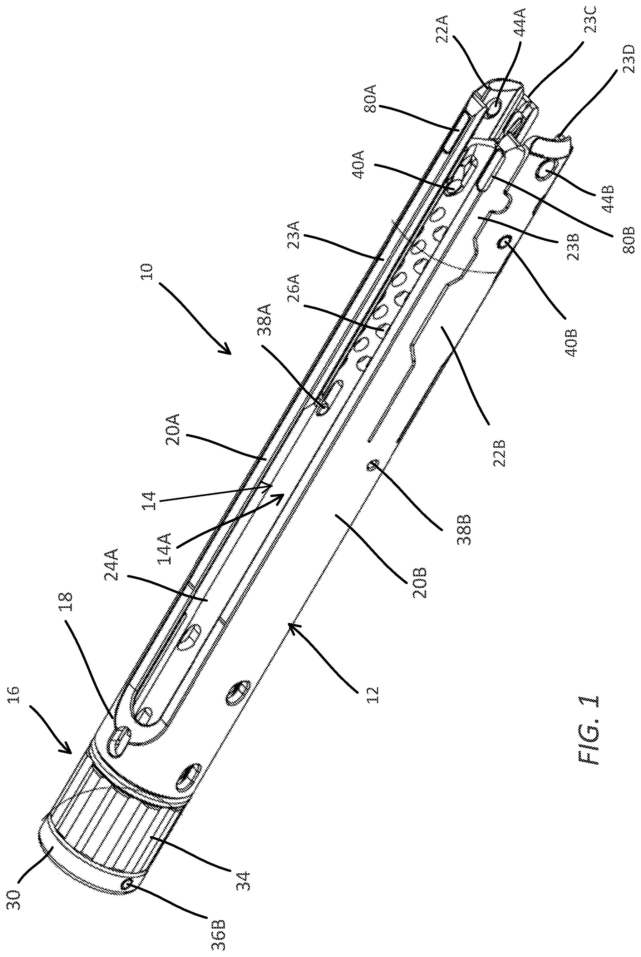
Turning first to , a perspective view of a pedicle screw tower 10 is shown. The pedicle screw tower 10 includes a tower body 12 , one or more inner slides 14 (visible in ) and a cap assembly 16 . The one or more inner slides 14 may comprise two inner slides 14 A and 14 B as illustrated, though in other embodiments the one or more inner slides 14 may comprise any number of slides. is an exploded perspective view of the pedicle screw tower 10 of . are discussed concurrently.
The tower body 12 can comprise a proximal portion 18 , a threaded end 19 , one or more extenders such as a first extender 20 A and a second extender 20 B, one or more deflectable arms such as a first deflectable arm 22 A and a second deflectable arm 22 B, and one or more deflectable prongs 23 such as deflectable prongs 23 A- 23 D. It will be appreciated that in other embodiments the one or more extenders may comprise any number of extenders, the one or more deflectable arms may comprise any number of deflectable arms, and the one or more deflectable prongs may comprise any number of deflectable prongs. The inner slide 14 A can comprise a coupling portion 24 A and an actuation portion 26 A and the inner slide 14 B can comprise a coupling portion 24 B and an actuation portion 26 B. The cap assembly 16 can comprise an outer ring 30 , an inner ring 32 , and a cap 34 . The pedicle screw tower 10 can further comprise one or more cap pins comprising cap pins 36 A and 36 B, one or more slide pins comprising slide pins 38 A and 38 B, one or more arm ramps comprising arm ramps 40 A and 40 B, one or more prong pins comprising prong pins 42 A- 42 D and one or more pedicle screw retainers comprising pedicle screw retainers 44 A and 44 B. It will be appreciated that in other embodiments the one or more cap pins may comprise any number of cap pins, the one or more arm ramps may comprise any number of arm ramps, the one or more prong pins may comprise any number of prong pins, and the one or more pedicle screw retainers may comprise any number of pedicle screw retainers.
The cap 34 can be rotated to push and pull the inner slides 14 A and 14 B along the first extender 20 A and the second extender 20 B, respectively. The inner slides 14 A and 14 B can engage with the arm ramps 40 A and 40 B mounted to the deflectable arms 22 A and 22 B to cause the deflectable arms 22 A and 22 B to splay outward to release engagement with a housing 204 of a pedicle screw 200 (shown in ). Likewise, the prong pins 42 A- 42 D can be assembled with the inner slides 14 A and 14 B to engage with protrusions (e.g., one or more slide rails comprising slide rails 72 A- 72 D) of the deflectable prongs 23 A- 23 D to cause the deflectable prongs 23 A- 23 D to splay outward to release engagement with the housing 204 of the pedicle screw 200 (shown in ). The prong pins 42 A- 42 D can thus comprise actuation features. Additionally, as discussed in greater detail below, the inner slides 14 A and 14 B can lock with the deflectable arms 22 A and 22 B and the deflectable prongs 23 A- 23 D to prevent outward deflection.
The knob 34 can therefore be rotated to a first position (shown in A- 19 C ) to lock a tower 10 onto a pedicle screw housing, a second position (shown in A- 20 C ) to allow the deflectable arms 22 A and 22 B and the deflectable prongs 23 A- 23 D to slip onto a pedicle screw housing by deflecting, and a third position (shown in A- 21 C ) to push the deflectable arms 22 A and 22 B and the deflectable prongs 23 A- 23 D outward to release a pedicle screw housing.
Turning to , a side view of the tower body 12 showing a deflectable arm 22 B within a second extender 20 B is shown. In particular, the deflectable arm 22 B is shown positioned between the deflectable prongs 23 B and 23 D. The tower body 12 can comprise an end portion 18 at a proximal end. The end portion 18 can comprise a ring or other annular structure from which the first extender 20 A and the second extender 20 B can extend in a distal direction.
The second extender 20 B can include a pin hole 46 B configured to receive the pin 38 B (visible in ). The second deflectable arm 22 B can be formed from a portion of second extender 20 B via one or more break lines comprising break lines 48 B and 48 D. The second deflectable arm 22 B can include a mounting bore 50 B for the arm ramp 40 B (visible in ) and a coupler bore 52 B for receiving the retainer 44 B (visible in ).
The first extender 20 A can include a pin hole 46 A configured to the receive pin 38 A (visible ). The first deflectable arm 22 A can be formed from a portion of the first extender 20 A via the one or more break lines comprising break lines 48 A and 48 C. The first deflectable arm 22 A can include a mounting bore 50 A for the arm ramp 40 A (visible in ) and a coupler bore 52 A for receiving the retainer 44 A (visible in ).
The tower body 12 can additionally include one or more ports comprising ports 54 B and 60 B, as well as ports 54 A and 60 A (visible in ), configured to receive mating components from a reducer or another component. It will be appreciated that in other embodiments the one or more ports may comprise any number of ports.
It will be appreciated that the first extender 20 A and the second extender 20 B can include similar components as described throughout with “A” and “B” designators.
Turning to , a side view of the tower body 12 showing an opening 58 between the extenders 20 A and 20 B is illustrated. The opening 58 is configured to allow for the passage of an elongate fixation member, such as a rod or tether, or other implants or instrumentation into or through the extenders 20 A and 20 B. The proximal portion 18 of the tower body 12 can comprise the ports 60 A and 60 B (visible in ), which are configured to receive mating components from a reducer or another component. For example, the ports 54 A, 54 B, 60 A and 60 B form an array of equally spaced ports that can be coupled to a pair of tangs or projections from a reducer.
The expandable prong 23 A can comprise a first coupler socket 62 A and the expandable prong 23 B can comprise a second coupler socket 62 B. The expandable prongs 23 A and 23 B can form a portion of a u-shaped cutout 64 A therebetween, along with portions from the extenders 20 A and 20 B and the proximal portion 18 .
is a cross-sectional view of the tower body 12 taken at a section line 5 - 5 shown in . As shown, the tower body 12 can comprise the extenders 20 A and 20 B, the expandable prongs 23 C and 23 D, the port 60 B, and a proximal socket 61 . The expandable prong 23 C can comprise a third coupler socket 62 C and the expandable prong 23 D can comprise a fourth coupler socket 62 D. The expandable prongs 23 C and 23 D can form a u-shaped cutout 64 B therebetween, along with portions from the extenders 20 A and 20 B and the proximal portion 18 .
As can be seen in , the expandable prongs 23 C and 23 D additionally include one or more slide rails comprising slide rails 70 C and 70 D. It will be appreciated that in other embodiments the one or more slide rails may comprise any number of slide rails. The slide rail 70 C can comprise one or more rail segments comprising rail segments 72 C 1 , 72 C 2 and 72 C 3 . The slide rail 70 D can comprise the one or more rail segments comprising rail segments 72 D 1 , 72 D 2 and 72 D 3 . As can be seen in , the expandable prongs 23 A and 23 B can include the one or more slide rails comprising slide rails 70 A and 70 B. The slide rail 70 A can comprise the one or more rail segments comprising rail segments 72 A 1 , 72 A 2 and 72 A 3 and the slide rail 70 B can comprise the one or more rail segments comprising rail segments 72 B 1 , 72 B 2 and 72 B 3 (visible in C, 20 C, and 21 C ). It will be appreciated that the half of the tower body 12 shown in is a mirror image of the half of the tower body 12 shown on the other side of the section line 5 - 5 of .
The slide rails 70 A- 70 D can interact with corresponding slots 86 A and 86 B (visible in ) disposed on the on the inner slides 14 A and 14 B to facilitate sliding of the inner slides 14 A and 14 B against the prongs 23 A- 23 D. As discussed herein, the slide rails 70 A- 70 D can each comprise three axially aligned segments (e.g., rail segments 72 C 1 , 72 C 2 and 72 C 3 ) that interact with two axially aligned segments of the slot 86 A or 86 B (visible in ) on the inner slide 14 A or 14 B, thereby facilitating locking and expansion of the prongs 23 A- 23 D as discussed herein. The rail segments 72 C 1 , 72 C 2 and 72 C 3 can be formed in conjunction with the shape of the break line 48 C. That is, where the break line 48 C widens the width of the deflectable arm 22 A, gaps between the rail segments 72 C 1 , 72 C 2 and 72 C 3 are produced. Conversely, where the break line 48 C narrows the width of the deflectable arm 22 A, the rail segments 72 C 1 , 72 C 2 and 72 C 3 are produced.
is a proximal end view of the tower body 12 showing the slide rails 70 A, 70 B, 70 C and 70 D extending relative to an axis A. The slide rails 70 A and 70 B can be positioned closer to a first side of the proximal portion 18 , while the slide rails 70 C and 70 D can be positioned closer to a second side opposite the first side of the proximal portion 18 . As such, the inner slide 14 A can slide on the rails 70 A and 70 C adjacent the deflectable arm 22 A and the inner slide 14 B can slide on the rails 78 B and 70 D adjacent the deflectable arm 22 B.
As can be seen in , the slide rails 70 A, 70 B, 70 C and 70 D comprise cross-sectional profiles having lobed shapes. In the illustrated example, the lobed shaped comprise a circular profile that comprises approximately three-hundred degrees of a circle to provide a circular rail for the inner slides 14 A and 14 B to slide thereon. It will be appreciated that in other embodiments the lobed shapes may comprise a circular profile having greater than or less than three-hundred degrees of a circle. The lobed shape allows for immobilization of the inner slides 14 A and 14 B in five degrees of freedom, permitting only axial movement in the direction of axis A when engaged with the slots 86 A and 86 B, while restraining circumferential and radial movement.
is a close-up perspective view of a distal end of the tower body 12 of and showing one or more pedicle screw retainers comprising pedicle screw retainers 80 A- 80 D and the retainers 44 A and 44 B exploded therefrom. It will be appreciated that in other embodiments the one or more pedicle screw retainers may comprise any number of pedicle screw retainers. The retainers 44 A and 44 B can be disposed within the bores 52 A and 52 B. The retainers 80 A- 80 D can be disposed within the sockets 62 A- 62 D, respectively. The retainers 44 A and 44 B and the retainers 80 A- 80 D can include one or more radially inner surfaces comprising radially inner surfaces 82 A and 82 B and 84 A- 84 D, respectively, that are ramped with respect to the axis A to allow the housing 204 (shown in ) of the pedicle screw 200 (shown in ) to be inserted proximally into the tower body 12 . It will be appreciated that in other embodiments the one or more radially inner surfaces can comprise any number of radially inner surfaces. The radially inner surfaces 82 A and 82 B and 84 A- 84 D also prevent the housing 204 from sliding distally out of the tower body 12 without the deflectable arms 22 A and 22 B and the deflectable prongs 23 A- 23 D deflecting or splaying radially outward to release the retainers 44 A and 44 B and retainers 80 A- 80 D from engagement with the housing.
The deflectable arms 22 A and 22 B can be provided with the bores 50 A and 50 B, respectively, to receive the ramps 40 A and 40 B (shown in ). The ramps 40 A and 40 B can engage with the inner slides 14 A and 14 B to either lock the deflectable arms 22 A and 22 B (as shown in B- 19 C ), to not interfere with the deflectable arms 22 A and 22 B (as shown in B- 20 C ), or to push the deflectable arms 22 A and 22 B outward (as shown in B- 21 C ).
The ramps 40 A and 40 B, the retainers 44 A and 44 B, and the retainers 80 A- 80 D can be configured to have interference fits with the bores 50 A and 50 B, the bores 52 A and 52 B, and the sockets 62 A- 62 D, respectively. The bores 50 A, 50 B, 52 A and 52 B can comprise simple through bores. In other instances, the bores 50 A, 50 B, 52 A and 52 B can comprise any shaped bore. The sockets 62 A- 62 D can comprise elongate, capsule shaped bores 83 A- 83 D having counterbore portions 85 A- 85 D extending from one side. In other embodiments, the sockets 62 A- 62 D can comprise any shaped socket.
is a first side view of the inner slide 14 A showing the slide slots 86 A and 86 B, a locking window 88 and one or more pin holes comprising pin holes 90 A and 90 B. is a second side view of the inner slide 14 A of . are discussed concurrently. It will be appreciated that in other embodiments the one or more pin holes can comprise any number of pin holes. The inner slide 14 A and inner slide 14 B can include similar components with “A” and “B” designators.
The slide slots 86 A and 86 B can include one or more cutouts comprising cutouts 92 A and 92 B to break the slide slots 86 A and 86 B into proximal portions 86 A 1 and 86 B 1 and distal portions 86 A 2 and 86 B 2 . It will be appreciated that in other embodiments the one or more cutouts can comprise any number of cutouts. The inner slide 14 A can further comprise a pin hole 94 A for interaction with the pin 36 A (shown in ) and ports 96 A and 98 A for aligning with the ports 54 A and 56 A (shown in ) of the tower body 12 . The inner slide 14 A can additionally include a slot 100 A for interacting with the pin 38 A (shown in ) and one or more through-bores 102 for lightening the inner slide 14 A and enabling easier cleaning of the tower body 12 between usage. The pin holes 94 A and pin 36 A (shown in ) can be used to assemble the inner slide 14 A with the inner ring 32 (shown in ) and the outer ring 30 (shown in ). The slot 100 A can interact with the pin 38 A to help maintain the inner slide 14 A in an axial alignment with the deflectable arm 22 A, such as when the rail segments 72 A 1 - 72 A 3 and 72 C 1 - 72 C 3 disengage with the slide slots 86 A and 86 B.
is a cross-sectional view of the inner slide 14 A of showing a cross-sectional profile of the slide slots 86 A and 86 B. In the illustrated embodiment, the slide slots 86 A and 86 B have profiles shaped to receive rail segments 72 A 1 - 72 A 3 and 72 C 1 - 72 C 3 and can, thus, have circular profiles. However, in other embodiments, the rail segments 72 A 1 - 72 A 3 and 72 C 1 - 72 C 3 and the slide slots 86 A and 86 B can be configured to have other profiles that can engage in a slidable relationship.
is a perspective view of the threaded end 19 of . The threaded end 19 can comprise an annular body 104 , an external threading 106 , an internal channel 108 , a radial flange 110 and an axial extension 111 . The internal channel 108 can comprise one or more lobes comprising lobes 112 A- 112 D. It will be appreciated that in other embodiments the one or more lobes can comprise any number of lobes. The axial extension 111 can be configured to fit into the socket 61 (shown in ). The radial flange 110 can be configured to have approximately the same outer diameter of the proximal portion 18 . The external threading 106 can be configured to mate with internal threading of an internal channel 134 of the cap 34 (visible in ). The lobes 112 A and 112 C can be configured to receive the coupling portions 24 A and 24 B of the inner slides 14 A and 14 B, respectively. The lobes 112 B and 112 D of the internal channel 108 can be configured to receive mating components of a reducer in two different orientations.
is a perspective view of the inner ring 32 of . The inner ring 32 can comprise an annular body 114 , one or more bores comprising bores 116 A and 116 B, an internal channel 118 and a flange 120 . The internal channel 118 can comprise one or more lobes comprising lobes 122 A- 122 D. It will be appreciated that in other embodiments the one or more lobes can comprise any number of lobes and the one or more bores can comprise any number of bores. The bores 116 A and 116 B can be configured to receive the pins 36 A and 36 B to facilitate assembly of the cap assembly 16 . The lobes 122 A- 122 D of the internal channel 118 can be configured to align with the lobes 112 A- 112 D of the threaded end 19 (shown in ) to facilitate assembly with the coupling portions 24 A and 24 B of inner slides 14 A and 14 B and insertion of a feature of a reducer. The flange 120 can be configured to fit inside the internal channel 134 of cap 34 (visible in ). The flange 120 can include external threading to allow for engagement with threading on the internal channel 134 of the cap 34 (shown in ).
is a perspective view of the outer ring 30 of . The outer ring 30 can comprise an annular body 124 , one or more bores comprising bores 126 A and 126 B and an internal channel 128 . It will be appreciated that in other embodiments the one or more bores can comprise any number of bores. The annular body 124 can be configured to fit around the annular body 114 of the inner ring 32 . The bores 126 A and 126 B can be configured to receive the pins 36 A and 36 B (shown in ) to facilitate assembly of the cap assembly 16 .
is a perspective view of the cap 34 of . The cap 34 can comprise an annular body 130 , one or more grip features 132 , an internal channel 134 and a flange 135 . It will be appreciated that in other embodiments the one or more grip features can comprise any number of grip features. The annular body 130 can be configured to surround the annular body 104 of the threaded end 19 . In particular, threading provided on the internal channel 134 can be configured to mate with the external threading 106 of the threaded end 19 . In the illustrated embodiment, the one or more grip features 132 can comprise ribs to facilitate rotating of the cap 134 about the axis A. In other examples, the one or more grip features 132 can comprise knurling and the like.
In order to assemble the cap assembly 16 (shown in ), the axial extension 111 (shown in ) can be inserted into the socket 61 (shown in ) so that the radial flange 110 is flush with the proximal portion 18 of the tower body 12 . The inner slides 14 A and 14 B can be slid into the lobes 112 A and 112 C. The inner ring 32 can be positioned so that the bores 94 A and 94 B (shown in ) of the inner slides 14 A and 14 B align with the bores 116 A and 116 B. The cap 34 can then be threaded onto the threaded end 19 such that the flange 135 sits on the flange 120 . The outer ring 30 can be positioned adjacent to the flange 135 so that the bores 126 A and 126 B align with the bores 116 A and 116 B. The pins 36 A and 36 B can be inserted into the bores 126 A and 126 B and the bores 116 A and 116 B, respectively. The flange 135 of the cap 34 can be trapped between the flange 120 of the inner ring 32 and the outer ring 30 . Thus, as the cap 34 is threaded up and down along the axis A, the inner slides 14 A and 14 B can be pushed and pulled along to activate features illustrated in with the pedicle screw housing 204 (shown in ).
is a perspective view of the retainer 44 A of . The retainer 44 A can comprise a radially inner surface 82 A and an external surface 136 of a body 138 . The body 138 can be configured to be interference fit into the bore 52 A or the bore 52 B (shown in ). The external surface 136 can be configured to be flush with the outer surface of the tower body 12 . The inner surface 82 A can be disposed at an angle to the external surface 136 . The body 138 and the bores 52 A and 52 B can be oblong in shape such that the slope of the internal surface 82 A can be directionally aligned relative to the axis A. The slope of the internal surface 82 A can be oriented such that the internal surface 82 A increases in height moving proximally and decrease in height moving distally. As such, the pedicle screw housing 204 (shown in ) moving proximally into the tower body 12 can displace the deflectable arms 22 A and 22 B, but once inserted the pedicle screw housing cannot be pulled distally without active deflection of the arms 22 A and 22 B.
is a perspective view of the arm ramp 40 A of . The arm ramp 40 A can comprise a post 140 , a ramp 142 and a lock 144 . The post 140 can be configured to be inserted into one of the bores 50 A and 50 B (shown in ). The posts 140 and the bores 50 A and 50 B can be configured to have an interference fit. The posts 140 can engage the deflectable arms 22 A and 22 B and the arm ramp 40 A can be oriented such that the ramps 142 moves a distance that increases in height moving proximally and decreases in height moving distally. As such, the deflectable arms 22 A and 22 B are displaced outward when slides 14 A and 14 B are moved proximally to engage the ramps 142 . The lock 144 can comprise a flange extending out from the post 140 in the opposite direction of the ramp 142 . The lock 144 can be configured to be positioned over one of the slides 14 A and 14 B to trap one of the deflectable arms 22 A and 22 B against one of the slides 14 A and 14 B, as shown in B .
A is a perspective view of the pedicle screw retainer 80 A of . B is a front view of the pedicle screw retainer 80 A of A . The body 146 can further comprise an extension 148 . The extension 148 can be configured to be seated in one of the counterbores 85 A and 85 B (shown in ).
is a perspective view of a distal end of an assembled pedicle screw tower 10 of the present application showing an assembly of features configured to hold the pedicle screw housing 204 (shown in ) and splay the deflectable arms 22 A and 22 B and the deflectable prongs 23 A- 23 D of the tower body 12 to release the pedicle screw housing 204 .
A is a side view of the cap assembly 16 of showing the cap 34 in a fully advanced position. The cap 34 can be abutted against the proximal portion 18 of the tower body 12 . Thus, the cap 34 can be positioned to move the inner slides 14 A and 14 B (shown in ) to their distal-most positions. B and 19 C show the distal end of tower 10 with the cap 34 in the position of A .
B is cross-sectional view of the distal end of the tower 10 of showing the arm ramps 40 A and 40 B of the deflectable arms 22 A and 22 B locked with the windows 88 of the inner slides 14 A and 14 B and the retainers 44 A and 44 B of the deflectable arms 22 A and 22 B engaged with the pedicle screw housing 204 . The retainers 44 A and 44 B can be disposed in the sockets 228 A and 228 B, respectively, of the housing 204 . The locks 144 of the ramps 40 A and 40 B can be engaged with the corresponding flanges 150 on the windows 88 of the inner slides 14 A and 14 B to retain the deflectable arms 22 A and 22 B against the inner slides 14 A and 14 B, thereby preventing the deflectable arms 22 A and 22 B from being able to be deflected radially outward.
C is side view of the distal end of tower 10 of showing rail segments 72 B 2 and 72 D 2 of the deflectable prongs 23 B and 23 D engaged with the slots 86 A and 86 B of the inner slide 14 B and the pedicle screw retainers 80 B and 80 D of the deflectable prongs 23 B and 23 D engaged with the pedicle screw housing 204 . The retainers 80 B and 80 D can be disposed in the sockets 224 A and 224 B, respectively, of the housing 204 . The rail segment 72 B 2 can engage the slot segment 86 A 1 . The rail segment 72 B 3 can engage the slot segment 86 A 2 . The rail segment 72 D 2 can engage the slot segment 86 B 1 . The rail segment 72 D 3 can engage the slot segment 86 B 2 . Thus, the deflectable prongs 23 B and 23 D can be prevented from moving radially outward.
A is a side view of the cap assembly 16 of showing the cap 34 in a partially retracted position. The cap 34 can be rotated to engage the threading 106 (shown in ) to move away from the proximal portion 18 of the tower body 12 such that a portion of the threaded end 19 can be exposed. As the cap 34 moves, the inner slides 14 A and 14 B can be pulled proximally. B and 20 C show the distal end of the tower 10 with the cap 34 in the position of A .
B is cross-sectional view of the distal end of tower 10 of showing the arm ramps 40 A and 40 B of the deflectable arms 22 A and 22 B positioned within the windows 88 of the inner slides 14 A and 14 B and the retainers 44 A and 44 B of the deflectable arms 22 A and 22 B engaged with the pedicle screw housing 204 . The retainers 44 A and 44 B can still be disposed in the sockets 228 A and 228 B, respectively, of the housing 204 . The locks 144 of the ramps 40 A and 40 B can be disengaged with the corresponding flanges 150 on the windows 88 of the inner slides 14 A and 14 B to allow the deflectable arms 22 A and 22 B to be capable of radial outward deflection.
C is side view of the distal end of tower 10 of showing the rail segments 72 B 2 and 72 D 2 of the deflectable prongs 23 B and 23 D disengaged with the slots 86 A and 86 B of the inner slide 14 B and the pedicle screw retainers 80 B and 80 D of the deflectable prongs 23 B and 23 D engaged with the pedicle screw housing 204 . The retainers 80 B and 80 D can still be disposed in the sockets 224 A and 224 B, respectively, of the housing 204 . The rail segment 72 B 2 can be disengaged from the slot segment 86 A 1 . The rail segment 72 B 3 can be disengaged from the slot segment 86 A 2 . The rail segment 72 D 2 can be disengaged from the slot segment 86 B 1 . The rail segment 72 D 3 can be disengaged from the slot segment 86 B 2 . Thus, the deflectable prongs 23 B and 23 D can be allowed to deflect radially outward.
A is a side view of the cap assembly 16 of showing the cap 34 in a fully retracted position. The cap 34 can be rotated to engage the threading 106 (shown in ) to move away from the proximal portion 18 of the tower body 12 such that a portion of the threaded end 19 and the threading 106 can be exposed. As the cap 34 moves, the inner slides 14 A and 14 B can be pulled proximally. B and 21 C show the distal end of the tower 10 with the cap 34 in the position of A .
B is cross-sectional view of the distal end of the tower 10 of showing the arm ramps 40 A and 40 B of the deflectable arms 22 A and 22 B interfering with the windows 88 of the inner slides 14 A and 14 B. This causes the retainers 44 A and 44 B of the deflectable arms 22 A and 22 B to disengage with the pedicle screw housing 204 (not shown). The windows 88 of the inner slides 14 A and 14 B can be pushed onto the ramps 142 of the ramps 40 A and 40 B to push the deflectable arms 22 A and 22 B radially outward. Thus, as can be seen in , the retainers 44 A and 44 B can be deflected radially outward, so as to be capable of withdrawal from the sockets 228 A and 228 B, respectively, of the housing 204 .
C is side view of the distal end of the tower 10 of showing the rail segments 72 B 2 and 72 D 2 of the deflectable prongs 23 B and 23 D interfering with the prong pins 42 B and 42 D of the inner slide 14 B. This causes the pedicle screw retainers 80 B and 80 D of the deflectable prongs 23 B and 23 D to disengage with the pedicle screw housing 204 (not shown). Thus, as can be seen in , the retainers 80 B and 80 D can be deflected radially outward, so as to be capable of withdrawal from the sockets 224 A and 224 B, respectively, of the housing 204 .
is a perspective view of the distal end of the tower 10 of B and 21 C with the deflectable arms 22 A and 22 B and the deflectable prongs 23 A- 23 D in a splayed state so as to be pushed radially outward from the center axis A of the tower body 12 and away from the inners slides 14 A and 14 B. As such, spaces or gaps can form between the deflectable prongs 23 A and 23 C and the deflectable arm 22 A, and between the deflectable prongs 23 B and 23 D and the deflectable arm 22 B, thereby producing clearance for the pedicle screw housing 204 to move axially in and out of the tower body 12 .
is a perspective view of the pedicle screw 200 (also referred to as a bone anchor) comprising a threaded fastener 202 and a rod housing 204 . The threaded fastener 202 can comprise a shaft 206 , a threading 208 , a head 210 and a socket 212 . The rod housing 204 can comprise a base portion 214 , an aperture 215 , a first extension 216 A, a second extension 216 B, a first open face 218 A, a second open face 218 B, a first closed face 220 A, a second closed face 220 B and a channel 222 . The first open face 218 A can comprise a first socket 224 A and a second socket 224 B. The first closed face 226 A can comprise a first socket 228 A.
The rod housing 204 can be rotated relative to the threaded fastener 202 to position the extensions 216 A and 216 B in different positions. The shaft 206 can be rotated within the base portion 214 via rotational engagement of the socket 212 with an instrument such as, for example, a screwdriver. A fixation element, such as a rod or tether, can be positioned between the extensions 216 A and 216 B and secured therein with a set screw. Although not seen in , the housing 204 can comprise counterpart sockets to the sockets 224 A, 224 B and 228 A on the far side of the housing 204 on open and closed faces. The sockets 224 A and 224 B can be provide alongside a channel formed by the extensions 216 A and 216 B on the open face 218 A, and the socket 228 A can be formed on the closed face 226 A. The socket 224 A and its counterpart socket can lie in a plane transverse to the central axis A of the tower 10 . The socket 224 B and its counterpart socket can lie in a plane transvers to the central axis A of the tower 10 . The socket 228 A and its counterpart socket can lie in a plane transverse to the central axis A of the tower 10 . The planes of the sockets 224 A and 224 B and their counterparts can be transverse to the plane of the socket 228 A and its counterpart.
The systems, devices and methods discussed in the present application can be useful in performing spinal correction procedures using extenders or towers that can couple to bone anchor or pedicle screw housings. The present disclosure describes tower extenders that can attach to a bone anchor housing in multiple circumferential locations around the perimeter of the pedicle screw housing relative to a center axis of the tower extender. Further, the tower extenders can be attached axially to the housing without rotation of the tower extenders. In other words, the tower extenders can be pushed onto the housing to engage with the pedicle screw. The attachment points of the tower extenders can be arranged in pairs that are orthogonal to each other to allow for secure attachment to the bone anchor housing. The attachment points can comprise protrusions that can extend into mating recesses in the bone anchor housing. The reverse configuration can additionally be used. The protrusions can be mounted to deflectable members of the tower extender. The deflectable members can be freely deflectable to allow the tower extender to slip over the bone anchor housing. The deflectable members can additionally be prevented from deflecting to prevent the bone anchor housing from separating from the tower extender. The deflectable members can additionally be pushed radially outward to facilitate disengagement of the protrusions from the recesses. The deflectable members can be locked and pushed via axially sliding of a slide arrangement or actuation mechanism within the tower extender. As such, the tower extenders of the present disclosure can provide robust attachment to a pedicle screw housing to prevent undesirable detachment during a procedure, but can be easily operated and actuated by a control knob to prevent and allow detachment and attachment.
Turning to A- 54 , a reducer 300 according to at least one embodiment of the present disclosure is described. A is a side view of the reducer 300 for the pedicle screw tower 10 (shown in ) of the present disclosure. The reducer 300 comprises a palm handle 302 , a reducer assembly 304 and a reducing shaft 306 . The palm handle 302 can comprise a grip 314 and a button 315 . B is a perspective view of the reducer 300 of A with the palm handle 302 removed to show a proximal end of a driver 308 . The reducer assembly 304 can comprise a clutch mechanism 310 and a locking mechanism 312 . A and 24 B are discussed concurrently below.
The reducer 300 can be used in conjunction with the pedicle screw tower 10 (shown in ) to push an elongate stabilization member, such as a rod 522 (shown ), into the pedicle screw housing 204 (shown in ). For example, with the pedicle screw tower 10 attached to the housing 204 , as shown in B and 19 C , the reducing shaft 306 can be inserted into the ring 30 (shown in ) and the proximal socket 61 (shown in ) of the tower body 12 . The reducer 300 can be advanced along the tower 10 so that the locking mechanism 312 of the reducer assembly 304 attaches to the ports 54 A- 54 B or 60 A- 60 B (shown in ). The locking mechanism 312 can be operated to allow the reducer assembly 304 to slide freely over the tower body 12 and then to lock onto the tower body 12 . The clutch mechanism 310 can be operated to allow the reducing shaft 306 to slide freely through the reducer assembly 304 until engaged with the stabilization member. The clutch mechanism 310 can then be adjusted to engage threading of the threaded shaft portion 330 on the reducing shaft 306 . The palm handle 302 can be rotated to mechanically push the reducing shaft 306 , as well as the stabilization member, into the pedicle screw housing 204 . Thereafter, the driver 308 can be operated through the palm handle 302 , or with the palm handle 302 removed, to push a closure device, e.g., a set screw or a closure device 521 (shown in ), into engagement with the housing 204 to lock the stabilization member in engagement with the pedicle screw housing 204 . The driver 308 can be spring loaded to position a pre-loaded closure device within the reducing shaft 306 . The driver 308 can be advanced distally by an operator to engage the closure device with the pedicle screw housing 204 .
As described with reference to , the reducer 300 can incorporate a linearly biased and actuated driver, such as the driver 308 or a driver configured to “stab and grab”, for holding a closure device within the reducing shaft 306 while reducing is being performed and that can subsequently be deployed via the driver 308 to attach to the housing 204 to hold a stabilization element within the housing 204 .
As is described with reference to , the locking mechanism 312 can be operated in three operating states to allow the reducer 300 to freely slide on the tower body 12 in an open state, to attach to the tower body 12 in an unlocked state, and to lock the tower body 12 in a locked state.
As described with reference to , the clutch mechanism 310 can comprise a three-pawl chuck that can be operated in two operating states to allow the reducing shaft 306 to freely slide within the reducer assembly 304 , and to engage threading on the reducing shaft 306 to allow the reducing shaft 306 to be mechanically pushed within the reducer assembly 304 .
is an exploded perspective view of the palm handle of A . The palm handle 302 can comprise a socket 480 , a driver channel 482 , one or more windows 484 and a button seat 486 . It will be appreciated that in other embodiments the one or more windows can comprise any number of windows. A button 315 can be positioned in the button seat 486 and can comprise a first end 490 , a pivot 492 and a second end 494 . The button 315 can comprise an elongate body configured to rotate at the pivot 492 such as via a coupling of the button 315 to the palm handle 302 via a pin 496 . A biasing element such as, for example, a spring 500 or another biasing element can be positioned between the first end 490 and the button seat 486 . The second end 494 can include a tang 502 for engaging clutch the housing 319 (shown in ). An insert 512 can be positioned in the socket 480 and retained therein by a fastener 514 that can extend into a bore 516 to engage a bore 518 . The fastener 514 can be threaded into engagement with the bores 516 and 518 . The insert 512 can comprise a cylindrical body forming a passage 520 into which the clutch housing 319 (shown in ) can be inserted. One or more lugs such as lugs 522 A- 522 C can be positioned between adjacent lugs 354 of the clutch housing 319 , as can be seen in . It will be appreciated that in other embodiments the one or more lugs can comprise any number of lugs. The insert 512 can include a cutout 524 to accommodate the button seat 486 .
is an exploded view of reducer 300 of A showing the reducer assembly 304 , the reducing shaft 306 and the driver 308 . The reducer assembly 304 can comprise the clutch mechanism 310 and the locking mechanism 312 . The clutch mechanism 310 can comprise clutch knob 318 , the clutch housing 319 and the clutch washer 320 . The locking mechanism 312 can comprise the reducer body 322 , an upper release lever 324 A and a lower release lever 326 A. The reducing shaft 306 can comprise a shaft body 328 , a threaded shaft portion 330 , a first rail 332 A and a second rail 332 B. The driver 308 can comprise a knob 334 , an actuation portion 336 , shaft 338 and a tip 340 . The driver 308 can be connected to a plunger 342 , a ring 344 and a clip 346 . The actuation portion 336 can comprise one or more slots such as slots 348 and the plunger 342 can comprise one or more slots such as slots 350 .
The upper and lower release levers 324 A and 326 A of the reducer body 322 can be used to couple and uncouple the reducer assembly 304 from a pedicle screw extender, such as the tower 10 of . The shaft body 328 of the reducing shaft 306 can be inserted into a socket 374 (shown in ) of the reducer body 322 such that the threaded shaft portion 330 extends proximally of the clutch housing 319 . The clutch knob 318 can be rotated to a position to allow threading of the threaded shaft portion 330 to pass freely through the reducer body 322 and can be rotated to another position to allow threading of the threaded shaft portion 330 to engage the pawls 316 A- 316 C (shown in ) within the clutch housing 319 . The driver 308 can be inserted into the proximal end of the threaded shaft portion 330 such that a tip 340 can be positioned between the rails 332 A and 332 B of the reducing shaft 306 . The plunger 342 can be coupled to the actuation portion 336 and a spring 508 (shown in ) can bias the shaft 338 proximally (shown in ). The knob 334 can be linearly actuated by a user in the distal direction to move the shaft 338 distally from the retracted position to selectively engage a closure device with a pedicle screw housing.
is a perspective view of the reducer assembly 304 of comprising the clutch mechanism 310 and the locking mechanism 312 . is an exploded view of the reducer assembly 304 of . are discussed concurrently.
The clutch housing 319 can comprise one or more lugs such as lugs 354 , a channel 356 , flange 358 , a cylinder portion 360 , one or more windows such as windows 362 A- 362 C and a threaded end 364 . The clutch mechanism 310 can further comprise one or more pawls such as pawls 316 A- 316 C and one or more springs such as springs 366 . It will be appreciated that in other embodiments the one or more lugs can comprise any number of lugs, the one or more windows can comprise any number of windows, the one or more pawls can comprise any number of pawls, and the one or more springs can comprise any number of springs.
The reducer body 322 can comprise a ring portion 368 , one or more legs such as legs 370 A and 370 B, a socket 374 , one or more lever tracks such as lever tracks 376 A and 376 B, one or more springs such as springs 378 and one or more pins such as pins 380 . The legs 370 A and 370 B can comprise one or more pin holes such as pin holes 382 A and 382 B and one or more lock holes such as lock holes 384 A and 384 B, respectively. It will be appreciated that in other embodiments the one or more lever tracks can comprise any number of lever tracks, the one or more springs can comprise any number of springs, the one or more pins can comprise any number of pins, the one or more pin holes can comprise any number of pin holes, and the one or more lock holes can comprise any number of lock holes.
The lugs 354 can be coupled in a mating fashion with a socket 480 (shown in ) in the palm handle 304 . The pawls 316 A- 316 C can be positioned in the windows 362 A- 362 C and the springs 366 or other resilient members can be positioned between the pawls 316 A- 316 C and the backstops 396 (shown in ) to bias the pawls 316 A- 316 C to a retracted position away from a center axis CA (shown in ) of the clutch housing 319 . The clutch knob 318 can be positioned over the cylinder portion 360 to the retain pawls 316 A- 316 C therein. The washer 320 can be positioned around the threaded end 364 to provide a bearing between the clutch housing 319 and the reducer body 322 . The threaded end 364 can be inserted into the socket 374 and the fastener 352 can be used to secure clutch the housing 319 to the reducer body 322 via a threaded engagement. The clutch housing 319 and the reducer body 322 can rotate relative to each other about the center axis CA of the reducer 300 . The upper release levers 324 A and 324 B and the lower release levers 326 A and 326 B can be attached to the lever tracks 376 A and 376 B, respectively, via the pins 380 . Thus, each of the upper release levers 324 A and 324 B and the lower release levers 326 A and 326 B can be pivotable about one of the pins 380 to move the rockers 466 in and out of the lock holes 384 A and 384 B, respectively. The springs 378 (or other resilient members) can be used to bias the upper release levers 324 A and 324 B away from the center axis of the reducer body 322 . As explained with reference to , the upper release levers 324 A and 324 B and the lower release levers 326 A and 326 B can be configured to interact, respectively, to provide three different levels of functionality to the rockers 466 .
is a perspective view of the reducer body 322 of the reducer assembly 304 of . is a cross-sectional view of the reducer body 322 of . are discussed concurrently. The reducer body 322 can comprise the ring portion 368 , the legs 370 A and 370 B, the socket 374 , the lever tracks 376 A and 376 B, the pin holes 382 A and 382 B and the lock holes 384 A and 384 B, as discussed previously. The reducer body 322 can further comprise an end flange 386 , one or more side surfaces such as side surfaces 388 A and 388 B, one or more bores such as bores 390 A and 390 B and bores 392 A and 392 B. It will be appreciated that in other embodiments the one or more side surfaces can comprise any number of side surfaces and the one or more bores can comprise any number of bores.
The reducer body 322 can comprise a platform upon which other components of the reducer 300 can be mounted or coupled. The threaded end 364 (shown in ) of the clutch housing 319 (shown in ) can be inserted into the socket 374 and can be attached thereto using the fastener 352 (shown in ). The fastener 352 can rest against the end flange 386 . Thus, the tower body 12 (shown in ) can be inserted into the space between the legs 370 A and 370 B to allow for coupling of the tower body 12 to the reducer body 322 . The ring 30 (shown in ) can rest against the fastener 352 , as shown in . The side surfaces 388 A and 388 B of the legs 370 A and 370 B that face each other can be curved to match the curvature of tower body 12 . The outer surfaces 373 A and 373 B of the legs 370 A and 370 B facing away from the central axis CA can be ergonomically contoured. For example, the legs 370 A and 370 B can include one or more protrusions such as protrusions 375 A and 375 B that can be used by a user to push against the reducer 300 with fingers, etc. It will be appreciated that in other embodiments the one or more protrusions can comprise any number of protrusions.
The upper and lower release levers 324 A, 324 B, 326 A, 326 B can be seated in the lever tracks 376 A and 376 B, respectively, to allow the rockers 466 (shown in ) to penetrate the lock holes 384 A and 384 B. The pin holes 382 A can receive the pins 380 to couple the upper release lever 324 A to the lever track 376 A and the pin holes 382 B can receive the pins 380 to couple the upper release lever 324 B to the lever track 376 B. The bores 390 A and 390 B and the bores 392 A and 392 B can facilitate cleaning of the reducer body 322 , such as by eliminating dead air space to allow cleaning and sterilizing material, e.g., steam, to reach spaces within the reducer body 322 .
is a perspective view of the clutch housing 319 of the reducer assembly 304 of . is a cross-sectional view of the clutch housing 319 of . are discussed concurrently. The clutch housing 319 can comprise the lugs 354 , the channel 356 , the flange 358 , the cylinder portion 360 , the windows 362 A- 362 C and the threaded end 364 . The clutch housing 319 can further comprise a channel 394 , one or more backstops such as backstops 396 and one or more bores such as bores 398 . It will be appreciated that in other embodiments the one or more backstops can comprise any number of backstops and the one or more bores can comprise any number of bores. The clutch housing 319 can additionally include other bores to facilitate cleaning of the clutch housing 319 , such as by eliminating dead air space to allow cleaning and sterilizing material, e.g., steam, to reach spaces within the clutch housing 319 .
The threaded end 364 can include external threading configured to mate with internal threading on the fastener 352 . The threaded end 364 can be sized to fit into the socket 374 (shown in ) of the reducer body 322 .
The cylinder portion 360 can engage the ring portion 368 (shown in ) of the reducer body 322 . The cylinder portion 360 can be sized to fit within the clutch knob 318 . The clutch knob 318 can rest against the flange 358 . The flange 358 can have an outer diameter that is approximately the same size as the outer diameter of the clutch knob 318 .
The windows 362 A- 362 C can be sized to receive the pawls 316 A- 316 C (shown in ). The windows 362 A- 362 C can be equally spaced about the perimeter of the cylinder portion 360 such that the pawls will push the reducing shaft 306 toward the center axis CA. The outer perimeter shape of the pawls 316 A- 316 C can be sized to mate with the outer shape of the windows 362 A- 362 C. The backstops 396 can be positioned at ends of the windows 362 A- 362 C to prevent the pawls 316 A- 316 C from passing through the windows 362 A- 362 C. The backstops 396 can additionally be used as surfaces for which the springs 366 (shown on ) can push off. The bores 398 can receive the springs 366 to prevent separation of the springs 366 from the reducer assembly 304 . The bores 398 can align with the bores 444 A and 444 B in the pawls 316 A- 316 C (shown in ).
The lugs 354 can be formed in the cylinder portion 360 on an opposite side of the flange 358 as the windows 362 A- 362 C. The lugs 354 and the cylinder portion 360 can be sized to fit within the socket 480 (shown in ) of the palm handle 302 . The lugs 354 can form grooves therebetween to provide rotational grips to a user of the reducer 300 when the palm handle 302 is removed. In additional examples, the socket 520 (shown in or 46 ) of the palm handle 302 can include the mating lugs 522 A- 522 C to fit between the lugs 354 to prevent relative rotation between the palm handle 302 and the clutch housing 319 . The channel 356 can extend around the cylinder portion 360 across the lugs 354 . The tang 502 of the button 315 (shown in ) can be positioned within the channel 356 to allow the palm handle 302 to be axially restrained on the clutch housing 319 .
is a first side view of the reducing shaft 306 of . is a second side view of the reducing shaft 306 of . is an end view of the reducing shaft 306 of from a proximal position looking distally. are discussed concurrently. The reducing shaft 306 can comprise the shaft body 328 , the threaded shaft portion 330 , the first rail 332 A, the second rail 332 B, an end 400 , one or more windows such as windows 402 , a bracket 404 , and a drive seat 406 .
The shaft body 328 can comprise an elongate, cannulated body that extends from the end 400 to the drive seat 406 . The end 400 can comprise a circular land or projection that can receive the ring 344 (shown in ). In additional examples, the end 400 can be threaded to receive mating threading on the ring 344 (shown in ). The drive seat 406 can comprise arcuate surfaces at the ends of the rails 332 A and 332 B that are shaped to abut a circular stabilization member, such as an elongate rod 522 (shown in ) that, in some examples, may be rigid. The threaded shaft portion 330 can extend from the end 400 along a length and can comprise external threading for engaging mating threading of the pawls 316 A- 316 C (shown in ). The shaft body 328 can comprise a cylindrical body configured to fit within the opening 58 (shown in ) between the extenders 20 A and 20 B of the tower body 12 . The rails 332 A and 332 B can extend along opposite sides of the shaft body 328 and can extend beyond the cylindrical portion of the shaft body 328 . The rails 332 A and 332 B can comprise elongate protrusions configured to fit within the lobes 112 B and 112 D of the threaded end 19 (shown in ) on the tower 10 . The windows 402 can extend along the shaft body 328 between the rails 332 A and 332 B. The windows 402 can allow for passage of cleaning material, e.g., steam, into the interior of the shaft body 328 . The bracket 404 can be located between the rails 332 A and 332 B and can include a socket or bore through which the driver 308 can extend. The bracket 404 can provide alignment of the driver 308 centrally between the rails 332 A and 332 B to facilitate insertion of the driver tip 340 with a housing of a pedicle screw.
is a perspective view of the clutch knob 318 of the reducer assembly 304 of . is a cross-sectional view of the clutch knob 318 of . are discussed concurrently. The clutch knob 318 can comprise an annular body 410 , a passage 412 , one or more ramps such as ramps 414 A, 414 B and 414 C, one or more bumps such as bumps 415 A, 415 B and 415 C, bumps 416 A, 416 B and 416 C, one or more pads such as pads 418 A, 418 B and 418 C, a flange 420 and one or more bores such as bores 422 . It will be appreciated that in other embodiments the one or more ramps can comprise any number of ramps, the one or more bumps can comprise any number of bumps, the one or more pads can comprise any number of pads, and the one or more bores can comprise any number of bores.
The annular body 410 can be sized to circumscribe the clutch housing 319 . The annular body 410 can comprise a user control configured to engage and disengage the reducer assembly 304 with the reducing shaft 306 by controlling a positioning of the pawls 316 A- 316 C. The inner diameter surfaces of the annular body 410 can comprise inner tracks for engaging the pawls 316 A- 316 C. Specifically, the ramps 414 A- 414 C can be configured to provide the annular body 410 with varying levels of thickness relative to the central axis CA that can be used to push the pawls 316 A- 316 C further into the windows 362 A- 362 C as the clutch knob 318 is rotated by a user. The pads 418 A- 418 C can comprise arcuate surfaces configured to ride against the cylinder portion 360 of the clutch housing 319 in portions between the windows 362 A- 362 C. The pads 418 A- 418 C can maintain the clutch knob 318 centered on the clutch housing 319 . Exterior-facing surfaces of the pawls 316 A- 316 C can ride against the ramps 414 A- 414 C. The bumps 415 A- 415 C can comprise projections or protrusions at the thinner ends of the ramps 414 A- 414 C to hold the pawls 316 A- 316 C in positions where the pawls 316 A- 316 C are disengaged with threading of the threaded shaft portion 330 (note, the bumps 415 A- 415 C are omitted from ). The bumps 416 A- 416 C can comprise projections or protrusions at the thicker ends of the ramps 414 A- 414 C to hold the pawls 316 A- 316 C in positions where the pawls 316 A- 316 C are engaged with threading of the threaded shaft portion 330 , as can be seen in . As such, the reducing shaft 306 can be moved in the axial direction within the clutch mechanism 304 via rotation of the clutch housing 319 . From the engaged position, the clutch knob 318 can be rotated clock-wise (relative to the orientation of ) to move the thinner portions of the ramps 414 A- 414 C to engage the pawls 316 A- 316 C. As such, the springs 366 can push against the backstops 396 to push the pawls 316 A- 316 C away from the threaded shaft portion 330 , as can be seen in . As such, the reducing shaft 306 can be freely moved in the axial direction within the clutch housing 319 . The ramps 414 A- 414 C can extend over approximately less than 25% of the clutch knob 318 between the bumps 416 A- 416 C and the pads 418 A- 418 C such that the pawls 316 A- 316 C can go from being fully withdrawn from the reducing shaft 306 to fully engaged with the reducing shaft 306 in a quarter turn of the clutch knob 318 or less. The the flange 420 can seat within clutch washer 320 (shown in ). The bores 422 can allow for can allow for passage of cleaning material, e.g., steam, into the interior of the clutch knob 318 .
is a side view of the plunger 342 for a closure top starter of the driver 308 of . is a cross-sectional view of the plunger 342 of . are discussed concurrently. The plunger 342 can comprise a cylindrical body 430 , a passage 432 , one or more slots such as slots 350 , one or more bores such as bores 434 and a rim 436 .
The plunger 342 can comprise a body that attaches to the actuation portion 336 of the driver 308 to control relative axial location of the driver 308 to the reducing shaft 306 . The pin 504 can be fixedly attached to the plunger 342 , but the driver 308 can move relative to the pin 504 via the slots 348 . Thus, the driver 308 will advance distally with the reducing shaft 306 under the power of the pawls 316 A- 316 C. However, once full reduction has been achieved, the driver 308 can be advanced further under manual axial power via a compression of the spring 508 (shown in ) such as by the application of axial force from a driver inserted into the socket 510 (shown in ).
The internal passage 432 can be sized to receive the actuation portion 336 of the driver 308 (shown in ), while the rim 436 can be sized to receive the shaft 338 . The end surface 506 (shown in ) of the actuation portion 336 can abut the rim 436 when the driver 308 is in the fully extended position. The bores 434 can be sized to receive the pin 504 (shown in ). The spring 508 (shown in ) can be positioned against the pin 504 to bias the driver 308 in a proximal direction (e.g., to the left relative to ). The windows 350 can comprise elongate openings through the cylindrical body 430 to allow for visibility of the driver 308 therein.
With reference to , before a reduction operation, the driver 308 can be advanced by compressing the spring 508 to expose the tip 340 to grab a closure mechanism, e.g., a set screw. The spring 508 can be released such that the tip 340 and the closure mechanism are retracted between the rails 332 A and 332 B. Thereafter, a reduction procedure can be conducted to reduce a stabilization element with the reducing shaft 306 . Once the stabilization element is positioned within the pedicle screw housing, the driver 308 can again be manually advanced to compress the spring 508 to engage the closure mechanism with the pedicle screw housing. Torque can be applied to the driver 308 via the socket 510 to advance the closure mechanism into the pedicle screw housing.
is a front view of the pawl 316 A for the clutch mechanism 319 of . is a cross-sectional view of the pawl 316 A of . are discussed concurrently. The pawl 316 A can comprise a body 442 , one or more sockets such as sockets 444 A and 444 B, a guide 446 and a thread 448 . The pawls 316 B and 316 C ( ) can be configured similarly as the pawl 316 A. It will be appreciated that in other embodiments the one or more sockets can comprise any number of sockets.
The pawl 316 A can be configured to keep the thread 448 properly oriented for engagement with threading of the threaded shaft portion 330 . Thus, the body 442 of the pawl 316 A can be elongated in the axial direction of the reducer 300 and the tower 10 to prevent rotational misalignment (relative to the orientation of ) of the thread 448 . Likewise, the body 442 can have a thickness to maintain engagement with the window 362 A in the clutch housing 319 (shown in ) and prevent radial misalignment relative to the central axis of the reducer 300 . The body 442 can maintain engagement with the window 362 A regardless of the position of the pawl 316 A controlled by the clutch knob 318 . The body 442 can include a depression 449 (shown in ) to allow for engagement with the protrusions 416 A- 416 C and/or the protrusions 415 A- 415 C (shown in ). The guide 446 can have a thickness sufficient to extend the thread 448 into engagement with the threaded shaft portion 330 when in the extended position and to fully disengage the thread 448 from the threaded shaft portion 330 in the retracted position. The guide 446 is axially shorter than the body 442 to allow space for the sockets 444 A and 444 B to allow the pawl 316 A to engage with the springs 366 (shown in ). The sockets 444 A and 444 B can comprise bores into the body 442 to receive the springs 366 and maintain the springs 366 in engagement with the pawl 316 A. The thread 448 can comprise a segment of threading configured to mate with the threaded shaft portion 330 . The thread 448 can have sufficient thickness and a pitch to engage with threading on the threaded shaft portion 330 .
is a front view of the upper release lever 324 A for the locking mechanism 312 of . is a cross-sectional view of the upper release lever 324 A of . are discussed concurrently. The upper release lever 324 A can comprise a body 450 , a bore 452 , a socket 454 , a hinge 456 , a pivot bore 458 , a tooth 460 and one or more undulations 462 . It will be appreciated that in other embodiments the one or more undulations can comprise any number of undulations. The upper release lever 324 B can be configured similarly as the upper release lever 324 A.
The body 450 can extend from a first end at the pivot bore 458 to a second end at the tooth 460 . The first end can be thickened to allow for the pivot bore 458 . The body 450 can extend from the first end toward one side of the pivot bore 458 to allow the tooth 460 space to pivot. The bore 452 can be located in a middle portion of the body 450 and can comprise a through-bore configured to extend from an exterior surface of the upper release lever 324 A to an interior surface of the upper release lever 324 A. The socket 454 can be located in a middle portion of the body 450 and can comprise a blind end bore configured to receive the spring 378 (shown in ). The socket 454 can be located away from the pivot bore 458 to provide rotational force or torque about the pivot bore 458 . The tooth 460 can extend axially from the second end of the body 450 in a direction transverse to the pivot axis. The tooth 460 can extend in line with the axis of the body 450 (shown in ) and can thus project parallel to the center axis CA of the reducer 300 when the reducer body 322 is aligned with the axis, but the tooth 460 can be projected toward the reducer body 322 (shown in ) or away from reducer body 322 (shown in ) as the body 450 is pivoted at the pivot bore 458 . As such, the tooth 460 can be pivoted into three different positions to engage with the lower release lever 326 A.
is a front view of the lower release lever 326 A for the locking mechanism 312 of . is a cross-sectional view of the lower release lever 326 A of . are discussed concurrently. The lower release lever 326 A can comprise a body 464 , a rocker 466 , a socket 468 and a pivot bore 470 . The lower release lever 326 B can be configured similarly as the lower release lever 326 A.
The body 464 can extend from a first end at the rocker 466 to a second end at the socket 468 . The pivot bore 470 can be located in a central or middle portion of the body 464 to allow the rocker 466 and the socket 468 to each move closer to and further away from the reducer body 322 (shown in ). The rocker 466 can comprise a tooth or projection that can extend through the lock hole 384 A (shown in ) to engage the tower body 12 (shown in ). The distal or leading end 472 of the rocker 466 can comprise a planar surface angled or slanted relative to the center axis CA of the reducer 300 to allow the reducer 300 to be axially pushed down onto the tower body 12 . However, the proximal or trailing end 474 of the rocker 466 can comprise a planar surface orthogonal to the center axis CA of the reducer 300 to inhibit or prevent axially movement of the reducer 300 up from the tower body 12 .
The socket 468 can comprise a first flange 476 , a second flange 477 , a trough 478 and a channel 479 . The first flange 476 can have an angled outer surface to facilitate the first flange 476 lying flush with the lever track 376 A (shown in ) when the lower release lever 326 A is rotated (shown in ). The second flange 477 can be rounded to facilitate rotation against surfaces of the upper release lever 324 A (see ). The first flange 476 and second flange 477 can form inner and outer surfaces for engaging inner and outer surfaces of the tooth 460 of the upper release lever 324 A in the radial direction relative to the center axis CA of the reducer 300 . The trough 478 and the channel 479 can comprise axial surfaces for engaging the distal tip of the tooth 460 . Thus, depending on the rotational positions of the upper release lever 324 A and the lower release lever 326 A, the tooth 460 can engage the second flange 477 and the trough 478 (shown in ), the first flange 476 (shown in ) or the first flange 476 and the channel 479 (shown in ).
is a cross-sectional view of the reducer 300 of A showing the clutch mechanism 310 , the locking mechanism 312 and the driver 308 . The reducer 300 can be connected to the palm handle 302 . The palm handle 302 can comprise the socket 480 , the driver channel 482 , the windows 484 and the button seat 486 , as previously described. The button 315 can be positioned in the button seat 486 and can comprise the first end 490 , the pivot 492 and the second end 494 . The button 315 can comprise an elongate body configured to rotate at the pivot 492 such as via coupling of the button 315 to the palm handle 302 via the pin 496 . The first end 490 can include the bore 498 against which the spring 500 or another biasing element can be positioned to push against the button seat 486 . The second end 494 can include the tang 502 for engaging the clutch housing 319 (shown in ). The socket 510 can be located in the knob 334 of the driver 308 to receive a tool such as, for example, a torque wrench to rotate the driver 308 . The relative lengths of components of the reducer 300 can be selected such that alignment of various features can indicate that the reducing shaft 306 has reached full reduction. For example, the proximal end of the knob 334 can align with the bottom of the windows 484 when r the educing shaft 306 is fully extended and the driver 308 is retracted, which can be seen through the windows 484 when the palm handle 302 is attached. Additionally, the proximal end of the plunger 342 can align with the proximal end of the clutch housing 319 when the reducing shaft 306 is fully extended, which can be seen when the palm handle 302 is removed.
is a close-up cross-sectional view of the locking mechanism 312 of in a locked state. In the locked state, the springs 378 can rotate the upper release levers 324 A and 324 B outward such that the teeth 460 rotate the lower release levers 326 A and 326 B outward. In such a configuration, the teeth 460 push against the outer flanges 477 and the trough 478 . As such, the rockers 466 are constrained such that forces acting on the ends 472 and 474 (shown in ) from the tower body 12 cannot change the relative position of the teeth 460 relative to the socket 468 ( ). Thus, the reducer body 322 cannot be moved axially about the tower 10 without pressing of the upper release levers 324 A and 324 B inward. Interaction of the upper release levers 324 A and 324 B and the lower release levers 326 A and 326 B in the locked position of provides a robust coupling with the tower body 12 such that the reducer 300 will not be displaced from the tower 10 during operation of the reducer 300 without undue force.
is a close-up cross-sectional view of the locking mechanism 312 of in an unlocked state. In the unlocked state, the springs 378 can be pushed inward by application of force to the upper release levers 324 A and 324 B by a user. In the unlocked state, the springs 378 are partially compressed. As such, the teeth 460 can be moved to interact with the inner flange 476 . As such, application of force to the end 474 (shown in ) via the tower body 12 will not cause the rockers 466 to be displaced from the lock holes 384 A and 384 B such that the reducer 300 cannot be advanced proximally off the tower body 12 . However, application of force to the end 472 via the tower body 12 will cause the rockers 466 to be displaced from the lock holes 384 A and 384 B such that the reducer 300 can be advanced distally into position on the tower body 12 .
is a close-up cross-sectional view of the locking mechanism 312 of in an open state. In the open state, the springs 378 can be pushed inward by application of force to the upper release levers 324 A and 324 B by a user to fully compressed positions. As such, the teeth 460 can be moved to interact with the inner flange 476 and the channel 479 . As such, the rockers 466 can be manually withdrawn from the lock holes 384 A and 384 B to allow the reducer 300 to be pulled proximally off the tower body 12 .
is a close-up cross-sectional view of the clutch mechanism 310 of A in an unlocked state. is a close-up cross-sectional view of the clutch mechanism 310 of A in an unlocked state. are discussed concurrently.
The body 410 of clutch knob 318 can be rotated such that the thinner portion of the ramps 414 A- 414 C and/or the protrusions 415 A- 415 C are engaged with the pawls 316 A- 316 C. As such, the springs 366 can push the pawls 316 A- 316 C away from the threaded shaft portion 330 , thereby also withdrawing the thread 448 from engagement with the threading of the threaded shaft portion 330 . The reducing shaft 306 can therefore freely move in the axial direction within the clutch housing 319 . As such, the reducer 300 can be quickly attached to the reducing shaft 306 in a position to begin reduction of a stabilization member without having to manually crank the clutch housing 319 to engage the stabilization member.
is a close-up cross-sectional view of the clutch mechanism 310 of A in a locked state. is a close-up cross-sectional view of the clutch mechanism 310 of A in a locked state. are discussed concurrently.
The body 410 of the clutch knob 318 can be rotated such that the thicker portion of the ramps 414 A- 414 C and/or the protrusions 416 A- 416 C are engaged with the pawls 316 A- 316 C. As such, the clutch knob 318 can overcome the forces of the springs 366 to push the pawls 316 A- 316 C into the threaded shaft portion 330 , thereby also pushing the threads 448 into engagement with the threading of the threaded shaft portion 330 . The reducing shaft 306 can therefore only move in the axial direction within the clutch housing 319 via rotation of the clutch housing 319 . The clutch housing 319 can be rotated about the center axis CA of the reducer 300 to push the reducing shaft 306 and reduce the stabilization member.
is a cross-sectional view of the reducer 300 of the present disclosure being used to attach the closure device 521 to the pedicle screw housing 204 having the rod 522 therein using the driver 308 and the reducing shaft 306 .
The rails 332 A and 332 B of the reducing shaft 306 can be pushed distally or downward via the reducer 300 to push the rod 522 into the pedicle screw housing 204 . For example, rotation of the clutch housing 319 relative to the reducer body 322 with the threads 448 engaged with the reducing shaft 306 , can cause the drive seats 406 to extend further away from the reducer body 322 to provide reducing action. Additionally, the driver 308 can be advanced to push the closure device 521 , e.g., a set screw, into engagement with the pedicle screw housing 204 . The driver 308 can be rotated to cause the closure device 521 to rotate and engage threading within the pedicle screw housing 204 to lock the rod 522 into engagement with the pedicle screw housing 204 . Thereafter, the tower 10 and the reducer 300 can be removed from the pedicle screw housing 204 and the rod 522 will remain seated in the housing 204 via the closure device 521 .
The systems, devices and methods discussed in the present application can be useful in performing spinal surgical procedures using extenders for bone anchors or pedicle screws. The present disclosure describes extenders that provide easy and robust coupling to bone anchors or pedicle screws and facilitate minimally invasive implantation of a pedicle screw. The extenders are also capable of attaching axially to, for example, a pedicle screw without rotational motion between the pedicle screw tower and the pedicle screw. In other words, the pedicle screw tower may be pushed onto the pedicle screw to thereby releasably attach the pedicle screw tower to the pedicle screw. Additionally, the pedicle screw tower can attach radially around the pedicle screw. The present disclosure, for example, provides for extenders can include a plurality of pairs of deflectable members that attach to a bone anchor housing at different circumferential locations. A control knob can be set to allow the deflectable members to freely deflect, to lock the deflectable members to prevent deflection and to push the deflectable members radially outward. Further, the pedicle screw tower may be moved between a first position to lock onto a pedicle screw housing, a second position to allow deflectable arms deflectable prongs of the tower to slip onto a pedicle screw housing by deflecting, and a third position to push the deflectable arms and the deflectable prongs outward to release a pedicle screw housing via a knob.
The foregoing is not intended to limit the disclosure to the form or forms disclosed herein. In the foregoing Detailed Description, for example, various features of the disclosure are grouped together in one or more aspects, embodiments, and/or configurations for the purpose of streamlining the disclosure. The features of the aspects, embodiments, and/or configurations of the disclosure may be combined in alternate aspects, embodiments, and/or configurations other than those discussed above. This method of disclosure is not to be interpreted as reflecting an intention that the claims require more features than are expressly recited in each claim. Rather, as the following claims reflect, inventive aspects lie in less than all features of a single foregoing disclosed aspect, embodiment, and/or configuration. Thus, the following claims are hereby incorporated into this Detailed Description, with each claim standing on its own as a separate preferred embodiment of the disclosure.
Moreover, though the foregoing has included description of one or more aspects, embodiments, and/or configurations and certain variations and modifications, other variations, combinations, and modifications are within the scope of the disclosure, e.g., as may be within the skill and knowledge of those in the art, after understanding the present disclosure. It is intended to obtain rights which include alternative aspects, embodiments, and/or configurations to the extent permitted, including alternate, interchangeable and/or equivalent structures, functions, ranges or steps to those claimed, whether or not such alternate, interchangeable and/or equivalent structures, functions, ranges or steps are disclosed herein, and without intending to publicly dedicate any patentable subject matter.
VARIOUS NOTES & EXAMPLES
Example 1 is an extender tower couplable to a bone anchor, the extender tower comprising: an outer tower body extending along a longitudinal axis from a proximal portion to a distal portion, the tower body comprising: first and second deflectable arms at the distal portion configured to engage with a housing of a bone anchor; first and second ramp-locks located on the first and second deflectable arms, respectively; and a threaded portion located at the proximal portion; a cap configured to engage the threaded portion; a first inner slide comprising a first coupling portion configured to engage the cap and a first window configured to engage the first ramp-lock; and a second inner slide comprising a second coupling portion configured to engage the cap and a second window configured to engage the second ramp-lock; wherein the cap can be rotated to: move the first and second inner slides to engage the first and second ramp-locks to push the first and second deflectable arms outward; and move the first and second inner slides to engage the first and second ramp-locks to prevent outward movement of the first and second deflectable arms.
In Example 2, the subject matter of Example 1 optionally includes wherein the outer tower body further comprises: first and second deflectable prongs extending alongside the first deflectable arm; and third and fourth deflectable prongs extending alongside the second deflectable arm.
In Example 3, the subject matter of Example 2 optionally includes wherein the first and second deflectable arms and the first through fourth deflectable prongs include features for engaging a housing of a fastener.
In Example 4, the subject matter of any one or more of Examples 2-3 optionally include wherein: the first inner slide includes first and second actuation features to push the first and second deflectable prongs outward; and the second inner slide includes third and fourth actuation features to push the third and fourth deflectable prongs outward.
In Example 5, the subject matter of Example 4 optionally includes wherein the first through fourth actuation features comprise pins configured to engage ramps of the first through fourth prongs.
In Example 6, the subject matter of any one or more of Examples 2-5 optionally include wherein: the first and second deflectable arms are configured to mate with closed faces of the bone anchor housing; and the first through fourth deflectable prongs are configured to mate with open faces of the bone anchor housing.
In Example 7, the subject matter of any one or more of Examples 1-6 optionally include wherein the tower body further comprises first and second rails extending axially alongside the first deflectable arm; and the first inner slide comprises first and second slots configured to receive the first and second rails.
In Example 8, the subject matter of Example 7 optionally includes wherein: the first and second rails comprise a plurality of intermittent rail segments; and the first and second slots comprises a plurality of intermittent slot segments.
In Example 9, the subject matter of Example 8 optionally includes wherein the plurality of intermittent rail segments and the plurality of intermittent slot segments are configured to, when engaged, permit axial sliding and prevent radial and circumferential displacement.
Example 10 is an extender tower for a bone anchor, the extender tower comprising: an outer tower body extending along a longitudinal axis, the tower body comprising: first and second deflectable arms disposed in opposing arrangement in a first radial direction; first and second deflectable prongs disposed in opposing arrangement in a second radial direction; a slide arrangement configured to slide within the outer tower body to engage the first and second deflectable arms and the first and second deflectable prongs; and a cap connected to the slide arrangement and configured to move axially relative to the outer tower body to move the slide arrangement; wherein the slide engagement is configured to engage the first and second deflectable arms and the first and second deflectable prongs in different axial positions including: a first axial position configured to radially interlock the slide arrangement with the first and second deflectable arms and the first and second deflectable prongs; a second axial position configured to allow the first and second deflectable arms and the first and second deflectable prongs to freely deflect; and a third axial position configured to push the first and second deflectable arms and the first and second deflectable prongs radially outward.
In Example 11, the subject matter of Example 10 optionally includes wherein the first and second deflectable arms are configured to deflect in a plane disposed orthogonal to a plane in which the first and second deflectable prongs are configured to deflect.
In Example 12, the subject matter of any one or more of Examples 10-11 optionally include third and fourth deflectable prongs.
In Example 13, the subject matter of any one or more of Examples 10-12 optionally include wherein the slide arrangement can comprise first and second inner slides having slots configured to slide with rails of the outer tower body.
In Example 14, the subject matter of Example 13 optionally includes wherein the first and second inner slides include windows configured to engage with ramps of the first and second deflectable arms to push the first and second deflectable arms radially outward.
In Example 15, the subject matter of any one or more of Examples 13-14 optionally include wherein the first and second inner slides include features configured to engage with protrusions of the first and second deflectable prongs to push the first and second deflectable prongs radially outward.
Example 16 is a method of operating a tower extender in conjunction with a bone anchor housing, the method comprising: positioning a plurality of deflectable members of a distal end of the tower extender proximate the bone anchor housing; pushing the distal end of the tower extender into engagement with the bone anchor housing to flex the plurality of deflectable members around the bone anchor housing to attach the tower extender relative to the bone anchor housing; rotating a knob to lock the plurality of deflectable members from deflecting away from the bone anchor housing; performing a portion of a surgical procedure with the tower extender; rotating the knob to deflect the plurality of deflectable members away from the bone anchor housing; and puling the tower extender away from the bone anchor housing.
In Example 17, the subject matter of Example 16 optionally includes wherein pushing the distal end of the tower extender into engagement with the bone anchor housing to flex the plurality of deflectable members around the bone anchor housing to attach the tower extender relative to the bone anchor housing comprises: rotating the knob to a position wherein the plurality of deflectable members are freely deflectable.
In Example 18, the subject matter of any one or more of Examples 16-17 optionally include wherein pushing the distal end of the tower extender into engagement with the bone anchor housing to flex the plurality of deflectable members around the bone anchor housing to attach the tower extender relative to the bone anchor housing comprises: deflecting first and second pairs of deflectable members radially outward relative to an axis of the tower extender, wherein the first and second pairs of deflectable members are aligned orthogonally to each other.
In Example 19, the subject matter of any one or more of Examples 16-18 optionally include wherein rotating a knob to lock the plurality of deflectable members from deflecting away from the bone anchor housing comprises: pushing a slide along the tower extender to interlock with each of the plurality of deflectable members to prevent radially outward deflection.
In Example 20, the subject matter of any one or more of Examples 16-19 optionally include wherein rotating the knob to deflect the plurality of deflectable members away from the bone anchor housing comprises: Pushing a slide along the tower extender to push each of the plurality of deflectable members radially outward.
Each of these non-limiting examples can stand on its own, or can be combined in various permutations or combinations with one or more of the other examples.
The above detailed description includes references to the accompanying drawings, which form a part of the detailed description. The drawings show, by way of illustration, specific embodiments in which the invention can be practiced. These embodiments are also referred to herein as “examples.” Such examples can include elements in addition to those shown or described. However, the present invention also contemplates examples in which only those elements shown or described are provided. Moreover, the present invention also contemplates examples using any combination or permutation of those elements shown or described (or one or more aspects thereof), either with respect to a particular example (or one or more aspects thereof), or with respect to other examples (or one or more aspects thereof) shown or described herein.
In the event of inconsistent usages between this document and any documents so incorporated by reference, the usage in this document controls.
In this document, the terms “a” or “an” are used, as is common in patent documents, to include one or more than one, independent of any other instances or usages of “at least one” or “one or more.” In this document, the term “or” is used to refer to a nonexclusive or, such that “A or B” includes “A but not B,” “B but not A,” and “A and B,” unless otherwise indicated. In this document, the terms “including” and “in which” are used as the plain-English equivalents of the respective terms “comprising” and “wherein.” Also, in the following claims, the terms “including” and “comprising” are open-ended, that is, a system, device, article, composition, formulation, or process that includes elements in addition to those listed after such a term in a claim are still deemed to fall within the scope of that claim. Moreover, in the following claims, the terms “first,” “second,” and “third,” etc. are used merely as labels, and are not intended to impose numerical requirements on their objects.
The above description is intended to be illustrative, and not restrictive. For example, the above-described examples (or one or more aspects thereof) may be used in combination with each other. Other embodiments can be used, such as by one of ordinary skill in the art upon reviewing the above description. The Abstract is provided to comply with 37 C.F.R. § 1.72(b), to allow the reader to quickly ascertain the nature of the technical disclosure. It is submitted with the understanding that it will not be used to interpret or limit the scope or meaning of the claims. Also, in the above Detailed Description, various features may be grouped together to streamline the disclosure. This should not be interpreted as intending that an unclaimed disclosed feature is essential to any claim. Rather, inventive subject matter may lie in less than all features of a particular disclosed embodiment. Thus, the following claims are hereby incorporated into the Detailed Description as examples or embodiments, with each claim standing on its own as a separate embodiment, and it is contemplated that such embodiments can be combined with each other in various combinations or permutations. The scope of the invention should be determined with reference to the appended claims, along with the full scope of equivalents to which such claims are entitled.
Figures (20)
Citations
This patent cites (18)
- US5941885
- US2010/0063552
- US2011/0184469
- US2013/0090697
- US2013/0110124
- US2013/0245705
- US2015/0105831
- US2015/0351810
- US2015/0359571
- US2016/0331420
- US2018/0214190
- US2019/0142471
- US2019/0365425
- US2020/0187987
- US2020/0188034
- US2020/0305932
- US2023/0052647
- US3539491