Abstract
An automobile hood 1 has an inner panel 2 , an outer panel 3 , and a plurality of linear sealer regions A in which joints 21 are arranged. A region which includes the linear sealer region A and in which both ends in a longitudinal direction L of the linear sealer region A reach the outer circumferential edge of the inner panel 2 is defined as an end-to-end region B. Each of three longest linear sealer regions A 2 , A 4 and A 3 among the plurality of linear sealer regions A is a length that is 40% or more of the length of an end-to-end region B 2 , B 4 or B 3 to which the linear sealer regions A 2 , A 4 or A 3 belongs, respectively. These three end-to-end regions B 2 , B 4 and B 3 do not intersect with each other within a region surrounded by the outer circumferential edge of the inner panel 2.
Claims (14)
1. An automobile hood, comprising: an inner panel, an outer panel, a sealer, and a joint that, in the sealer, is a portion which joins the inner panel and the outer panel, wherein: a direction in which a linear sealer region in which the sealer is continuously arranged linearly extends is defined as a longitudinal direction; a region of the inner panel that is a region which includes the linear sealer region and in which both ends in the longitudinal direction reach an outer circumference of the inner panel is defined as an end-to-end region; at least three of the linear sealer regions are provided at intervals in at least one of a front-rear direction of the automobile hood and a width direction of the automobile hood; each of three longest linear sealer regions among the plurality of linear sealer regions has a length that is 40% or more of a length of the end-to-end region to which the linear sealer region itself belongs, and the joint is formed therein; and three end-to-end regions that include the three longest linear sealer regions among the plurality of linear sealer regions do not intersect with each other within a region that is surrounded by an outer circumferential edge of the inner panel.
Show 13 dependent claims
2. The automobile hood according to claim 1 , wherein: the length is a length when the automobile hood is seen in plan view.
3. The automobile hood according to claim 1 , wherein: in at least one of the plurality of linear sealer regions, the joints are intermittently arranged in the longitudinal direction.
4. The automobile hood according to claim 1 , wherein: in at least one of the plurality of linear sealer regions, the joint extends continuously along the longitudinal direction.
5. The automobile hood according to claim 1 , wherein: at least one pair of linear sealer regions among the plurality of the linear sealer regions are arranged in parallel with each other.
6. The automobile hood according to claim 1 , wherein: the inner panel includes a unit; the unit includes a flange that is arranged adjacent to the outer panel, an inclined wall that extends from the flange so as to separate from the outer panel, and a bottom portion that is continuous with the inclined wall and is separated from the flange; and in at least one of the plurality of linear sealer regions, the joint is provided on the flange.
7. The automobile hood according to claim 6 , wherein: the flange of the unit is formed in an annular shape; and in at least one of the plurality of linear sealer regions, all of the joints are arranged at places that are offset from a center of the annular-shaped flange.
8. The automobile hood according to claim 6 , wherein: a plurality of the units are provided in the inner panel; and in at least one of the plurality of linear sealer regions, the joint is provided on the flange in each of a plurality of the units.
9. The automobile hood according to claim 6 , wherein: a plurality of the units having the same shape are arranged in the front-rear direction and the width direction of the automobile hood.
10. The automobile hood according to claim 1 , wherein: the sealer includes a reinforcing sealer; the linear sealer region includes an end portion joint that is arranged at an endmost portion in the longitudinal direction among the joints of the linear sealer region; and the reinforcing sealer connects together end portions of the end portion joints of the plurality of linear sealer regions in which the longitudinal directions are different.
11. The automobile hood according to claim 10 , wherein: the reinforcing sealer cooperates with the sealers of the plurality of linear sealer regions to form an annular sealer.
12. The automobile hood according to claim 1 , wherein: the inner panel is a steel sheet panel having a thickness of 0.25 mm to 0.80 mm, or is an aluminum alloy panel having a thickness of 0.40 mm to 1.20 mm.
13. The automobile hood according to claim 1 , wherein: the outer panel is a steel sheet panel having a thickness of 0.25 mm to 0.80 mm, or is an aluminum alloy panel having a thickness of 0.40 mm to 1.20 mm.
14. The automobile hood according to claim 1 , wherein: in three longest linear sealer regions, a portion of the sealer that is separated from either one of the inner panel and the outer panel is a non-joint portion; and in each of the three longest linear sealer regions, the joint and the non-joint portion are alternately arranged in the longitudinal direction.
Full Description
Show full text →
TECHNICAL FIELD
The present invention relates to an automobile hood.
BACKGROUND ART
Patent Document 1 discloses a hood panel for a vehicle. The principle purpose of the hood panel is to reduce the degree of injury to a pedestrian if the pedestrian collides with the hood panel.
Patent Document 2 discloses a hood for an automobile as exterior equipment for an automobile. The principle purpose of the hood for an automobile is to absorb the energy of contact when a pedestrian comes into contact with the hood for an automobile, by only deforming by a small amount in the inward direction of the automobile.
LIST OF PRIOR ART DOCUMENTS
Patent Documents
Patent Document 1: JP2005-193863A
Patent Document 2: JP2017-1553A
SUMMARY OF INVENTION
Technical Problem
In the automobile hood disclosed in Patent Document 1, an inner panel and an outer panel are joined using an adhesive. Mastic sealers and the like are known as adhesives for joining an inner panel and an outer panel. When assembling an automobile hood, for example, a mastic sealer is applied to the outer panel, and next, by superposing the inner panel and the outer panel on each other, the mastic sealer is sandwiched between the inner panel and the outer panel. By this means, the inner panel and the outer panel are joined to each other through the mastic sealer.
The operation to apply the mastic sealer to the outer panel is performed, for example, by a robot arm that holds a nozzle to which the sealer is supplied. From the viewpoint of shortening the time required for the application process through efficient application of the mastic sealer, the operation to apply the mastic sealer that is performed by the robot arm is preferably performed while moving the nozzle along the simplest possible path. On the other hand, if the amount of mastic sealer is reduced in order to shorten the time required for the operation to apply the mastic sealer, the strength with which the inner panel supports the outer panel will be lowered.
In both Patent Document 1 and Patent Document 2, there is no particular disclosure regarding a configuration for efficiently applying an adhesive such as a mastic sealer.
One objective of the present invention is, with respect to an automobile hood, to enable an increase in the efficiency of an operation for joining an inner panel and an outer panel while making the joining strength with which the inner panel and the outer panel are joined to each other sufficiently high.
Solution to Problem
The gist of the present invention is an automobile hood which is described hereunder.
•
• (1) An automobile hood, including: • an inner panel, • an outer panel, • a sealer, and • a joint that, in the sealer, is a portion which joins the inner panel and the outer panel, • wherein: • a direction in which a linear sealer region in which the sealer is continuously arranged linearly extends is defined as a longitudinal direction; • a region of the inner panel that is a region which includes the linear sealer region and in which both ends in the longitudinal direction reach an outer circumference of the inner panel is defined as an end-to-end region; • at least three of the linear sealer regions are provided at intervals in at least one of a front-rear direction of the automobile hood and a width direction of the automobile hood; • each of three longest linear sealer regions among the plurality of linear sealer regions has a length that is 40% or more of a length of the end-to-end region to which the linear sealer region itself belongs, and the joint is formed therein; and • three end-to-end regions that include the three longest linear sealer regions among the plurality of linear sealer regions do not intersect with each other within a region that is surrounded by an outer circumferential edge of the inner panel. • (2) The automobile hood according to the above (1), wherein the length is a length when the automobile hood is seen in plan view. • (3) The automobile hood according to the above (1) or the above (2), wherein, in at least one of the plurality of linear sealer regions, the joints are intermittently arranged in the longitudinal direction. • (4) The automobile hood according to any one of the above (1) to the above (3), wherein, in at least one of the plurality of linear sealer regions, the joint extends continuously along the longitudinal direction. • (5) The automobile hood according to any one of the above (1) to the above (4), wherein at least one pair of linear sealer regions among the plurality of the linear sealer regions are arranged in parallel with each other. • (6) The automobile hood according to any one of the above (1) to the above (5), wherein: • the inner panel includes a unit, • the unit includes a flange that is arranged adjacent to the outer panel, an inclined wall that extends from the flange so as to separate from the outer panel, and a bottom portion that is continuous with the inclined wall and is separated from the flange; and • in at least one of the plurality of linear sealer regions, the joint is provided on the flange. • (7) The automobile hood according to the above (6), wherein: • the flange of the unit is formed in an annular shape; and • in at least one of the plurality of linear sealer regions, all of the joints are arranged at places that are offset from a center of the annular-shaped flange. • (8) The automobile hood according to the above (6) or the above (7), wherein: • a plurality of the units are provided in the inner panel, and • in at least one of the plurality of linear sealer regions, the joint is provided on the flange in each of a plurality of the units. • (9) The automobile hood according to any one of the above (6) to the above (8), wherein a plurality of the units having the same shape are arranged in the front-rear direction and the width direction of the automobile hood. • (10) The automobile hood according to any one of the above (1) to the above (9), wherein: • the sealer includes a reinforcing sealer, • the linear sealer region includes an end portion joint that is arranged at an endmost portion in the longitudinal direction among the joints of the linear sealer region, and • the reinforcing sealer connects together end portions of the end portion joints of the plurality of linear sealer regions in which the longitudinal directions are different. • (11) The automobile hood according to the above (10), wherein the reinforcing sealer cooperates with the sealers of the plurality of linear sealer regions to form an annular sealer. • (12) The automobile hood according to any one of the above (1) to the above (11), wherein the inner panel is a steel sheet panel having a thickness of 0.25 mm to 0.80 mm, or is an aluminum alloy panel having a thickness of 0.40 mm to 1.20 mm. • (13) The automobile hood according to any one of the above (1) to the above (12), wherein the outer panel is a steel sheet panel having a thickness of 0.25 mm to 0.80 mm, or is an aluminum alloy panel having a thickness of 0.40 mm to 1.20 mm. • (14) The automobile hood according to any one of the above (1) to the above (13), wherein: • in three longest linear sealer regions, a portion of the sealer that is separated from either one of the inner panel and the outer panel is a non-joint portion; and • in each of the three longest linear sealer regions, the joint and the non-joint portion are alternately arranged in the longitudinal direction.
Advantageous Effect of Invention
According to the present invention, the efficiency of an operation for joining an inner panel and an outer panel in an automobile hood can be increased while making the joining strength with which the inner panel and the outer panel are joined to each other sufficiently high.
BRIEF DESCRIPTION OF DRAWINGS
is a schematic exploded perspective view of an automobile hood according to one embodiment of the present invention, in which diagrammatic representation of a sealer is omitted.
is a plan view of an inner panel of the automobile hood.
is a schematic cross-sectional view along a line III-III in .
is a cross-sectional view along a line IV-IV in , in which illustration of a portion that appears to the rear of the cross-section is omitted.
is a view in which one part of is enlarged.
is a plan view in which one part of the inner panel illustrated in is enlarged.
is a perspective view in which one part of the inner panel is enlarged.
is a plan view of an inner panel of an automobile hood in a modification in which reinforcing sealers are provided in the embodiment.
is a schematic plan view of an inner panel and sealers pertaining to a first modification.
is a cross-sectional view along a line X-X in .
is a plan view of an inner panel of an automobile hood in a modification in which reinforcing sealers are provided in the first modification.
is a plan view of the inner panel of the modification of the first modification.
is a plan view of the inner panel of the automobile hood in an example in which reinforcing sealers are provided in the modification of the first modification.
is a plan view of an inner panel pertaining to a second modification of the present invention.
is a plan view of an inner panel of an automobile hood in an example in which reinforcing sealers are provided in the second modification.
is a plan view of an inner panel of a modification of the second modification.
is a plan view of the inner panel of the automobile hood in an example in which reinforcing sealers are provided in the modification of the second modification.
DESCRIPTION OF EMBODIMENT
Hereunder, first, the circumstances leading to the conception of the present invention will be described, and then an embodiment will be described in detail.
[Circumstances Leading to Conception of Present Invention]
Generally, in an automobile hood, the outer panel is a relatively flat shape, while on the other hand the inner panel is a shape having unevenness. Further, a sealer such as a mastic sealer is applied at places in the inner panel that are convex toward the outer panel side. The sealer contacts the inner panel and the outer panel and joins these panels together. Further, in the automobile hood, the height (thickness) in the vehicle height direction is less than the length in the vehicle length direction and the length in the vehicle width direction of the automobile. Therefore, when the sealer is to be applied to the outer panel or inner panel during assembling of the automobile hood, the amount of movement of a nozzle for applying the sealer in the directions (vehicle length direction and vehicle width direction) that are orthogonal to the thickness direction of the automobile hood influences the time taken to perform the sealer application operation. Hence, taking into consideration the magnitude of the influence on the total movement length of a nozzle for applying sealer during production of one automobile hood, the present inventors conceived of devising a suitable layout for sealer by taking a long region of sealer as a target, which is a region that easily contributes to shortening the sealer application time. As a result, the present invention has been conceived. Hereunder, one example of the present invention is specifically described.
DESCRIPTION OF EMBODIMENT
Hereunder, an embodiment of the present invention is described while referring to the accompanying drawings.
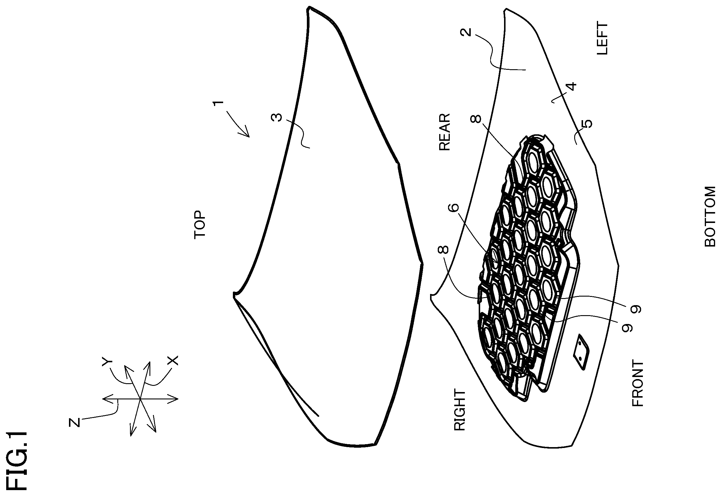
is a schematic exploded perspective view of an automobile hood 1 according to one embodiment of the present invention, in which diagrammatic representation of a sealer 20 is omitted. is a plan view of an inner panel 2 of the automobile hood 1 . is a schematic cross-sectional view along a line III-III in . is a cross-sectional view along a line IV-IV in , in which illustration of a portion that appears to the rear of the cross-section is omitted. Note that, in and , an outer panel 3 that does not appear in is indicated by a chain double-dashed line that is a virtual line.
is view in which one part of is enlarged. is a plan view in which one part of the inner panel 2 shown in is enlarged. is a perspective view in which one part of the inner panel 2 is enlarged. Hereinafter, unless otherwise noted, the embodiment will be described with reference to to as appropriate.
The automobile hood 1 is a front hood provided at the front part of an automobile, and is also called a “bonnet”. An automobile in which the automobile hood 1 is provided is, for example, a passenger vehicle. A sedan-type passenger vehicle, a coupe-type passenger vehicle, a hatchback-type passenger vehicle, a minivan-type passenger vehicle, an SUV (Sport Utility Vehicle) type passenger vehicle and the like can be mentioned as examples of the passenger vehicle.
Note that, in the present description, the terms “front”, “rear”, “left”, “right”, and “upper” and “lower” are used taking a time when the automobile hood 1 is mounted to an automobile and the automobile hood 1 is closed as the basis. The term “front” refers to the direction in which the automobile advances. The term “rear” refers to the direction in which the automobile reverses. The term “right” refers to the turning direction of the automobile when the automobile which is advancing turns to the right. The term “left” refers to the turning direction of the automobile when the automobile which is advancing turns to the left. Further, in the present embodiment, the vehicle width direction of the automobile to which the automobile hood 1 is mounted is referred to as “width direction X”. Further, the vehicle length direction of the automobile to which the automobile hood 1 is mounted is referred to as “longitudinal direction Y”. Furthermore, the vehicle height direction of the automobile to which the automobile hood 1 is mounted is referred to as “height direction Z”.
The automobile hood 1 has the inner panel 2 , the outer panel 3 that is supported by the inner panel 2 , sealers 20 provided between the inner panel 2 and the outer panel 3 , joints 21 which are portions of the sealers 20 which contact the outer panel 3 and the inner panel 2 and which are portions that join the panels 2 and 3 to each other, and non-joint portions 22 as portions of the sealers 20 that are separated from either one of the inner panel 2 and the outer panel 3 . Note that, in and , the sealers 20 are illustrated using thick lines.
In the automobile hood 1 , the outer panel 3 is a portion that constitutes a part of the outer surface of the automobile. The outer panel 3 is formed of, for example, a metal material such as a mild steel sheet or a high-tensile strength steel sheet. Examples of the high-tensile strength steel sheet that can be mentioned include steel sheets having a tensile strength of 340 MPa or more, for example, a steel sheet having a tensile strength of 590 MPa or more. The outer panel 3 is formed, for example, by subjecting a single steel sheet to press working or the like. In a case where the outer panel 3 is a steel sheet panel, the sheet thickness of the outer panel 3 is, for example, 0.25 mm to 0.80 mm. The outer panel 3 may be an aluminum alloy sheet. In a case where the outer panel 3 is an aluminum alloy panel, the sheet thickness of the outer panel 3 is, for example, 0.40 mm to 1.20 mm. There are no particular restrictions with regard to the shape of the outer panel 3 . Note that, in the present embodiment, the outer panel 3 has a shape in which the central portion is upwardly convex in the height direction Z.
The inner panel 2 reinforces the outer panel 3 by being joined to an undersurface 3 a of the outer panel 3 using the sealers 20 . By this means, the inner panel 2 increases the panel rigidity of the outer panel 3 . The inner panel 2 is formed, for example, of a metal material such as a steel sheet. The inner panel 2 is formed, for example, by subjecting a single steel sheet to press working. The inner panel 2 may be an integrally formed product, or may be formed by joining a plurality of members together. In the present embodiment, the inner panel 2 is an integrally formed product. In a case where the inner panel 2 is a steel sheet panel, the sheet thickness of the inner panel 2 (thickness of the steel sheet) is, for example, 0.25 mm to 0.80 mm. The sheet thickness of the inner panel 2 may be less than the sheet thickness of the outer panel 3 , may be the same as the sheet thickness of the outer panel 3 , or may be greater than the sheet thickness of the outer panel 3 . Note that, the inner panel 2 may be an aluminum alloy sheet. In a case where the inner panel 2 is an aluminum alloy panel, the sheet thickness of the inner panel 2 is, for example, 0.40 mm to 1.20 mm.
The inner panel 2 has an outer circumferential portion 4 in which a contour forming portion 5 is provided, and an overhanging structure 6 arranged so as to be surrounded by the contour forming portion 5 .
The outer circumferential portion 4 is an outer circumferential part of the inner panel 2 . When the outer panel 3 closes the engine room, the outer circumferential portion 4 of the inner panel 2 is received by the automobile body (not illustrated) together with the outer circumferential portion of the outer panel 3 . By this means, a load that acts on an upper face 3 b of the outer panel 3 is received by the automobile body through the inner panel 2 .
The contour forming portion 5 of the outer circumferential portion 4 is a three-dimensionally shaped portion formed at the outer circumferential part of the inner panel 2 , and is a portion at which the bending rigidity is enhanced among the entire outer circumferential portion 4 of the inner panel 2 . In the present embodiment, the contour forming portion 5 is formed over the entire area in the circumferential direction of the outer circumferential portion of the inner panel 2 . Note that, the contour forming portion 5 may be formed only at one part in the circumferential direction of the outer circumferential portion 4 of the inner panel 2 . The contour forming portion 5 includes a portion that rises and falls in the height direction Z when moved in the horizontal direction over the inner panel 2 . The overhanging structure 6 is arranged so as to be surrounded by the contour forming portion 5 .
The overhanging structure 6 has a three-dimensional structure which is provided in order to receive a load acting on the upper face 3 b of the outer panel 3 . The overhanging structure 6 has a configuration in which members that have a hat-shaped cross section (a V-shaped cross section or a U-shaped cross section) are combined.
The overhanging structure 6 has a plurality of incomplete units 8 that are adjacent to an inner circumferential edge portion 4 a of the outer circumferential portion 4 and continuous with the outer circumferential portion 4 , and a plurality of units 9 .
The unit 9 which is adjacent to the outer circumferential portion 4 of the inner panel 2 is connected to the outer circumferential portion 4 directly or through the incomplete unit 8 .
The incomplete unit 8 has a configuration equivalent to a configuration in which one portion of the unit 9 has been cut off along the circumferential direction of the polygonal (in the present embodiment, hexagonal) unit 9 . The incomplete unit 8 has a side portion that is similar to a sub-unit 10 of the unit 9 that is described later. The side portion is continuous with the inner circumferential edge portion 4 a of the outer circumferential portion 4 .
Although a configuration may be adopted in which only one unit 9 is provided, in the present embodiment a plurality of the units 9 are provided. Each unit 9 is formed in a polygonal (in the present embodiment, hexagonal) annular shape in plan view in the height direction Z. Hereinafter, when simply the term “plan view” is used, it means a plan view in the height direction Z. By forming each unit 9 in a small annular shape (in the present embodiment, a polygonal annular shape), the inner panel 2 can be made lightweight and the inner panel 2 can also be provided with high rigidity.
In the present embodiment, each unit 9 is formed in the shape of a substantially regular hexagon with rounded corners. The term “regular hexagon” means a hexagon in which the lengths of the respective sides are equal and the interior angles are also a constant angle of 120 degrees. Further, in the present description, the term “substantially regular hexagon” refers to a hexagon that can be treated as a regular hexagon. The respective units 9 are formed so that the shape of each unit 9 is substantially the same. Note that, the term “substantially the same” in this case indicates that the configuration is the same except in the respect that the shape of each unit 9 is caused to match a shape which matches the curved shape of the outer panel 3 .
Each unit 9 may also be formed in the shape of a hexagon that is other than a regular hexagon. Examples of a hexagon other than a regular hexagon that can be mentioned include a hexagon in which the lengths of the respective sides are not uniform, and a hexagon in which the interior angles are not uniform at 120 degrees. Examples of a hexagon in which the lengths of the respective sides are not uniform that can be mentioned include a hexagon in which the length of a front end side and the length of a rear end side are set to a predetermined first length, and which has four sides, lengths of which are each set to a predetermined second length that is different from the first length.
The overhanging structure 6 has a structure in which a plurality of the units 9 having a hexagonal annular shape are disposed in a close-packed arrangement. In this case, the term “close-packed” means that a plurality of the units 9 that are adjacent to each other are arranged without a gap therebetween. Specifically, each unit 9 is partitioned off from the other units 9 by unit boundaries 14 . As illustrated in , a front end 13 c (lower end) of a bottom portion 13 forms a boundary of the bottom portion 13 that includes the front end 13 c , to thereby form the unit boundary 14 . The unit boundary 14 is formed in a hexagonal shape in plan view. By having such a structure in which the units 9 are disposed in a close-packed hexagonal arrangement, the overhanging structure 6 can withstand loads in substantially the same manner from all directions including the height direction Z over the whole area in plan view.
In a case where flanges 11 , described later, of the units 9 are disposed in a close-packed arrangement, preferably a plurality of the units 9 have the same shape. Further, the units 9 that have similar forms to each other and have differing shapes may be disposed in a close-packed arrangement. Note that, in the overhanging structure 6 , the units 9 need not be disposed in a close-packed arrangement, and another portion may be formed between the units 9 and 9 that are adjacent.
In the present embodiment, the plurality of the units 9 are formed symmetrically in the width direction X as a whole. For example, in the present embodiment, three of the units 9 are arranged side by side in the front-to-rear direction at the center in the width direction X. Note that, there is no constraint on the direction of the units 9 .
In the present embodiment, in the direction toward the right side from the aforementioned three units 9 arranged at the central position in the width direction X are provided, in the following order, four units 9 which are arranged side by side in the longitudinal direction Y, a further three units 9 which are arranged side by side in the longitudinal direction Y, a further two units 9 which are arranged side by side in the longitudinal direction Y, and a further two units 9 which are arranged side by side in the longitudinal direction Y. Furthermore, similarly to the foregoing arrangement, in the direction toward the left side from the aforementioned three units 9 arranged at the central position in the width direction X are provided, in the following order, four units 9 which are arranged side by side in the longitudinal direction Y, a further three units 9 which are arranged side by side in the longitudinal direction Y, a further two units 9 which are arranged side by side in the longitudinal direction Y, and a further two units 9 which are arranged side by side in the longitudinal direction Y. Thus, a plurality of the units 9 having the same shape are arranged in the longitudinal direction Y (front-rear direction) and the width direction X.
As illustrated clearly in and , each of the units 9 has six of the sub-units 10 ( 10 a to 10 f ). In the present embodiment, in each of the units 9 , a front sub-unit 10 a and a rear sub-unit 10 d extend along the width direction X, respectively. Further, in each of the units 9 , the remaining four sub-units 10 extend in a direction that inclines with respect to the longitudinal direction Y in plan view. The unit 9 that has a polygonal shape is formed by the plurality of sub-units 10 in this way.
Each of the sub-units 10 ( 10 a to 10 f ) has a flange 11 , an inclined wall 12 continuous with the flange 11 , and the bottom portion 13 that is continuous with the inclined wall 12 and is separated from the flange 11 .
The flange 11 is adjacent to the outer panel 3 , and in the sub-unit 10 , the flange 11 is a portion that is arranged closest to the outer panel 3 . The flange 11 is a strip-shaped portion. In a single unit 9 , outer circumferential portions of the flanges 11 of the six sub-units 10 a to 10 f form a hexagonal flange as a whole. Thus, in the present embodiment, in a single unit 9 , the plurality of flanges 11 are formed in an annular shape as a whole. Note that, the outer circumferential portions of the flanges 11 of the six sub-units 10 a to 10 f may, as a whole, form a flange having a polygonal shape other than a hexagon, and may form a substantially circular flange, or may form a flange having a substantially oval shape. Further, inner end portions 11 a of the six flanges 11 constitute an annular end portion which is centered on the center of the annular unit 9 as a whole. In the present embodiment, because the inner end portion 11 a of each flange 11 is formed in an arc shape which is centered on the center of the unit 9 , the inner end portions 11 a of the six flanges 11 are formed in a circular shape as a whole.
Note that, the inner end portions 11 a of the six flanges 11 may be formed in a polygonal shape as a whole, or may be formed in an elliptical shape as a whole. In the present embodiment, the plurality of flanges 11 in the plurality of units 9 are disposed in a close-packed arrangement. In an upper face 11 b of the flange 11 , a width to which a joint 21 can be applied is preferably 2 mm or more from the viewpoint that a sufficient amount of the joint 21 can be provided.
Each of the two end portions of the flange 11 in the longitudinal direction is formed in a curved shape in plan view, and smoothly connects with the flange 11 of an adjacent sub-unit 10 . In the present embodiment, in each unit 9 , the flanges 11 of at least some of the sub-units 10 are adhered to the joint 21 at the upper face 11 b , and are adhered to the outer panel 3 through the joint 21 . The inclined wall 12 extends downward from the flange 11 .
The inclined wall 12 is disposed between the flange 11 and the bottom portion 13 , and connects the flange 11 and the bottom portion 13 . The inclined wall 12 extends from the flange 11 so as to separate from the outer panel 3 . The inclined wall 12 is provided over the entire area in a longitudinal direction L of the sub-unit 10 in which the inclined wall 12 in question is provided. The inclined wall 12 is formed, for example, in a tapered shape that advances toward the central axis side (the inner end portion 11 a side) of the unit 9 as it approaches the outer panel 3 side.
The flange 11 is continuous with the upper end of the inclined wall 12 . The bottom portion 13 is continuous with the lower end of the inclined wall 12 . In the unit 9 , the bottom portion 13 is a portion that is farthest from the outer panel 3 , and is separated from the flange 11 . The bottom portion 13 is formed in a curved shape which is convex in the downward direction. The bottom portion 13 is provided over the entire area in the longitudinal direction of the sub-unit 10 in which the inclined wall 12 in question is provided. The flange 11 , the inclined wall 12 , and the bottom portion 13 are arranged in that order from the inner side to the outer side in the radial direction of the unit 9 . The front end 13 c of the bottom portion 13 in one unit 9 is integral with the front end 13 c of the bottom portion 13 in another unit 9 that is adjacent thereto.
Next, the sealer 20 will be described more specifically while referring mainly to , and . The sealer 20 is provided for joining the inner panel 2 and the outer panel 3 . In the present embodiment, the sealer 20 is an adhesive. A mastic sealer (mastic adhesive) can be exemplified as the adhesive. A resin-based adhesive can be exemplified as the mastic sealer. The adhesive may have a property of being cured at normal temperature (for example, 20 degrees Celsius), or may have a property of being cured by undergoing a heating process or a drying process.
The sealer 20 is arranged so as to secure the bonding strength between the inner panel 2 and the outer panel 3 while achieving a reduction in the weight of the automobile hood 1 . In the present embodiment, the sealer 20 is provided in each unit 9 of the inner panel 2 . In the present embodiment, the width of the sealer 20 (the dimension of the sealer 20 in the direction orthogonal to the extending direction of the sealer 20 in plan view) is about 5 mm to 25 mm. A portion of the sealer 20 that is in contact with both of the inner panel 2 and the outer panel 3 constitutes a joint 21 . Specifically, in the sealer 20 , a portion that is actually in contact with both of the inner panel 2 and the outer panel 3 is the joint 21 that joins these panels 2 and 3 to each other. The joint 21 joins the upper face 11 b of the flange 11 and the undersurface 3 a of the outer panel 3 . Thus, by the flange 11 of the inner panel 2 that is a flange which projects to the outer panel 3 side being joined to the outer panel 3 through the joint 21 , the inner panel 2 can support the outer panel 3 with high rigidity.
At least one part of the sealer 20 (in the present embodiment, all of the sealer 20 ) is arranged in a linear sealer region A. The term “linear sealer region A” refers to a region in which the sealer 20 is continuously provided and extends in a linear shape. The term “linear shape” in this case is not limited to the case of a true straight line, and also includes a case where the sealer 20 meanders or curves within a range of about three times the width of the sealer 20 in a direction orthogonal to the longitudinal direction of the sealer 20 in plan view. At least three (in the present embodiment, nine) of the linear sealer regions A are provided. In the present embodiment, the linear sealer regions A (A 1 to A 9 ) are provided. In the present embodiment, a place where the sealer 20 is provided is a sealer region (linear sealer region A).
In each of the linear sealer regions A 1 to A 9 , the direction in which the relevant linear sealer region A 1 to A 9 extends is defined as a longitudinal direction L (L 1 to L 9 ). The longitudinal direction L is a direction on a straight line connecting the center of one end and the center of the other end of the sealer 20 in each linear sealer region A. In the present embodiment, the respective longitudinal directions L 1 to L 6 of the linear sealer regions A 1 to A 6 are directions that extend from the lower left to the upper right in plan view, the longitudinal direction L 7 of the linear sealer region A 7 is a direction along the width direction X, and the respective longitudinal directions L 8 and L 9 of the linear sealer regions A 8 and A 9 are directions from the lower left to the upper right. Although in the longitudinal directions L 1 to L 6 are indicated collectively, they are different directions to each other.
In the present embodiment, the linear sealer region A 1 is arranged at the left end of the linear sealer regions A 1 to A 9 . Further, the linear sealer regions A 1 to A 6 which are parallel to each other are arranged from the left side to the right side. The linear sealer region A 7 is continuous with the front end of the linear sealer region A 1 , and in addition, the linear sealer regions A 7 and A 8 are continuous with each other. Further, the linear sealer region A 9 is continuous with the rear end of the linear sealer region A 3 .
Each of the linear sealer regions A 1 to A 9 is provided within the overhanging structure 6 . The linear sealer regions A 1 to A 5 extend over a plurality of the units 9 . Specifically, the linear sealer region A 1 extends over four of the units 9 that are arranged in series from the lower left to the upper right. The linear sealer region A 2 extends over six of the units 9 that are arranged in series from the lower left to the upper right. The linear sealer region A 3 extends over five of the units 9 that are arranged in series from the lower left to the upper right. The linear sealer region A 4 extends over five of the units 9 that are arranged in series from the lower left to the upper right. The linear sealer region A 5 extends over four of the units 9 that are arranged in series from the lower left to the upper right. The linear sealer region A 6 is arranged in one of the units 9 . Note that, the linear sealer regions A 7 and A 8 are arranged in the incomplete unit 8 at the front end. Further, the linear sealer region A 9 is arranged in the incomplete unit 8 on the rear end side.
In the present embodiment, in each unit 9 , only one linear sealer region A is provided. Specifically, in a direction orthogonal to the longitudinal direction L of the linear sealer regions A 1 to A 6 , the linear sealer region A is arranged only on one of a pair of end portions of each unit 9 . In other words, in the linear sealer regions A 1 to A 6 as at least one of the plurality of linear sealer regions, all the joints 21 are arranged at places that are offset from the center (the center point of the circle of the inner end portions 11 a ) of the flanges 11 . By means of the above configuration relating to the sealer 20 , the total weight of the sealer 20 in the automobile hood 1 can be reduced.
As mentioned above, each of the linear sealer regions A 1 to A 5 extends over a plurality of the units 9 . Therefore, each of the sealers 20 of the linear sealer regions A 1 to A 5 extends while rising and falling in the height direction Z. With regard to the linear sealer region A 6 also, the sealer 20 extends while rising and falling in the height direction Z. Further, in the sealer 20 of each of the linear sealer regions A 1 to A 6 , a portion that is mounted on the flange 11 constitutes the joint 21 . Specifically, the joints 21 are arranged in each of the linear sealer regions A 1 to A 6 . In each of the linear sealer regions A 1 to A 5 , the joints 21 are intermittently arranged in the longitudinal direction L. In the sealer 20 of each of the linear sealer regions A 1 to A 5 , a place that is mounted on the flange 11 constitutes the joint 21 as described above. Specifically, the respective sealers 20 of the linear sealer regions A 1 to A 5 form respective joints 21 at the flanges 11 of a plurality of the units 9 . On the other hand, in the sealer 20 of each of the linear sealer regions A 1 to A 6 , a place arranged on the inclined wall 12 or the bottom portion 13 constitutes a non-joint portion 22 which does not join the inner panel 2 and the outer panel 3 to each other. In each of the linear sealer regions A 1 to A 6 , the joints 21 and the non-joint portions 22 are alternately arranged in the corresponding longitudinal direction L 1 to L 6 . In each of the linear sealer regions A 1 to A 5 , approximately 70% of the region is the joints 21 , and the remaining about 30% of the region is the non-joint portions 22 . In the linear sealer regions A 7 to A 9 , a portion of the sealer 20 that is mounted on the flange 11 of the incomplete unit 8 constitutes the joint 21 . Thus, in the present embodiment, the joint 21 is formed in each of the linear sealer regions A 1 to A 9 . Note that, it suffices that the joint 21 is formed in at least three longest linear sealer regions A 2 , A 4 and A 3 among the plurality of linear sealer regions A 1 to A 9 .
In the present embodiment, at least three of the linear sealer regions A are provided at intervals in at least one of the longitudinal direction Y as the front-rear direction of the automobile hood 1 and the width direction X. Specifically, in the vicinity of the center of the automobile hood 1 in the width direction X, the linear sealer region A 2 is arranged diagonally to the rear of the linear sealer regions A 1 , A 7 , and A 8 . In addition, diagonally to the rear of the linear sealer region A 2 , the linear sealer regions A 3 , A 4 , and A 5 are arranged in that order toward the rear. The linear sealer region A 9 is arranged to the rear of the linear sealer region A 3 . Further, the linear sealer region A 6 is arranged on the diagonally rear side of the linear sealer region A 5 . Thus, in the present embodiment, at least three of the linear sealer regions A are provided at intervals in both of the longitudinal direction Y and the width direction X.
In the present embodiment, a region of the inner panel 2 which includes one linear sealer region A and in which both ends in the longitudinal direction L reach the outer circumferential edge of the inner panel 2 is defined as an end-to-end region B. In other words, a region of the automobile hood 1 which includes one linear sealer region A and which is present along the longitudinal direction L is defined as an end-to-end region B. It can also be said that the end-to-end region B is a region of the inner panel 2 which includes the linear sealer region A and which is aligned in the longitudinal direction L with the linear sealer region A (which includes the linear sealer region A and regions aligned with the linear sealer region A).
More specifically, end-to-end regions B 1 to B 9 that include the linear sealer regions A 1 to A 9 , respectively, are defined. In plan view, the end-to-end region B 1 is a region of the inner panel 2 that includes the linear sealer region A 1 and in which both ends in the longitudinal direction L of the linear sealer region A 1 reach the outer circumferential edge of the inner panel 2 . In the present embodiment, a pair of end portions B 1 a and B 1 b of the end-to-end region B 1 are located at the left rear edge and the front edge of the inner panel 2 , respectively. Similarly, in plan view, the end-to-end regions B 2 to B 4 are regions of the inner panel 2 that include the corresponding linear sealer regions A 2 to A 4 and in which both ends in the corresponding longitudinal directions L 2 to L 4 of the linear sealer regions A 2 to A 4 reach the outer circumferential edge of the inner panel 2 . In the present embodiment, the respective pairs of end portions B 2 a and B 2 b , B 3 a and B 3 b , and B 4 a and B 4 b of the end-to-end regions B 2 to B 4 are located at the left rear edge and the front edge of the inner panel 2 , respectively. Further, in plan view, the end-to-end regions B 5 and B 6 are regions of the inner panel 2 that include the corresponding linear sealer regions A 5 and A 6 and in which both ends in the corresponding longitudinal directions L 5 and L 6 of the linear sealer regions A 5 and A 6 reach the outer circumferential edge of the inner panel 2 . In the present embodiment, the respective pairs of end portions B 5 a and B 5 b , and B 6 a and B 6 b of the end-to-end regions B 5 and B 6 are located at the rear edge and the right edge of the inner panel 2 , respectively.
In the present embodiment, three longest linear sealer regions A in lengths in the longitudinal direction L among the linear sealer regions A 1 to A 9 are, in order of longest length, the linear sealer regions A 2 , A 4 , and A 3 . In plan view, the lengths of the three longest linear sealer regions A 2 , A 4 , and A 3 among the plurality of linear sealer regions A are 40% or more of the lengths of the end-to-end regions B 2 , B 4 and B 3 to which the linear sealer regions A 2 , A 4 and A 3 themselves belong, respectively. Specifically, in plan view, in these longest linear sealer regions A 2 , A 4 , and A 3 , the proportion of the respective lengths with respect to the lengths of the corresponding end-to-end regions B 2 , B 4 and B 3 in the corresponding longitudinal directions L 2 to L 4 is 40% or more respectively. More specifically, in plan view, in the longitudinal direction L 2 , the proportion of the length of the linear sealer region A 2 with respect to the length between the end portions B 2 a and B 2 b of the end-to-end region B 2 is 40% or more. Further, in plan view, in the longitudinal direction L 3 , the proportion of the length of the linear sealer region A 3 with respect to the length between the end portions B 3 a and B 3 b of the end-to-end region B 3 is 40% or more. Further, in plan view, in the longitudinal direction L 4 , the proportion of the length of the linear sealer region A 4 with respect to the length between the end portions B 4 a and B 4 b of the end-to-end region B 4 is 40% or more.
The grounds for setting the respective lengths of the three longest linear sealer regions A 2 , A 4 , and A 3 among the plurality of linear sealer regions A to 40% or more of the respective lengths of the corresponding end-to-end regions B 2 , B 4 and B 3 to which the linear sealer regions A 2 , A 4 and A 3 themselves belong in this way is as follows. Specifically, in the automobile hood 1 , for reasons pertaining to the design and the design space, in a region up to a maximum of about 30% of an outer circumferential side portion of the automobile hood 1 , (1) the rigidity of the outer panel 3 is high and it is not necessary for the region to be stiffened using the inner panel 2 . Alternatively, (2) it is difficult to set the linear sealer region A because it is difficult to stiffen the region using the inner panel 2 due to interference with other components. Therefore, it is possible to set the length of the sealer region A to (100%−2×30%=) 40% or more of the length of the linear sealer region B. By forming these regions A 2 , A 4 and A 3 in a long linear shape and also providing the joints 21 in each of these regions A 2 , A 4 and A 3 , the efficiency of the operation for joining the inner panel 2 and the outer panel 3 can be increased while making the joining strength with which the inner panel 2 and the outer panel 3 are joined to each other sufficiently high.
In the present embodiment, the lengths of the linear sealer regions A other than the three longest linear sealer regions A in lengths in the longitudinal direction L among the linear sealer regions A 1 to A 9 are not particularly defined except for the point that the lengths are shorter than the lengths of the three longest linear sealer regions A 2 , A 4 and A 3 .
Further, in the present embodiment, the end-to-end regions B 2 , B 4 and B 3 of the aforementioned three longest linear sealer regions A 2 , A 4 and A 3 among the plurality of linear sealer regions A 1 to A 9 are arranged so that intersection of the end-to-end regions B 2 , B 4 and B 3 with each other is avoided (the end-to-end regions B 2 , B 4 and B 3 are separated). In the present embodiment, the end-to-end regions B 2 , B 4 and B 3 are arranged in a linear shape extending from the lower left to the upper right in plan view, and are substantially parallel to each other. Hence, the end-to-end regions B 2 , B 4 and B 3 do not intersect with each other in the region surrounded by the outer circumferential edge of the inner panel 2 .
In the present embodiment, in each unit 9 , the joints 21 of the linear sealer regions A 1 to A 6 are arranged over two flanges 11 and 11 that are adjacent to each other. Specifically, in each unit 9 , the joints 21 are arranged over the flanges 11 of the sub-units 10 c and 10 d . Further, only one linear sealer region A of the plurality of linear sealer regions A is passed over one unit 9 .
Further, in the present embodiment, in plan view, the joints 21 are arranged in a well-balanced manner in the automobile hood 1 . Specifically, the joints 21 are arranged on both sides of the center of the automobile hood 1 in the width direction X, and are scattered in a region of at least 40% or more of the total width of the automobile hood 1 . Similarly, the joints 21 are arranged on both sides of the center of the automobile hood 1 in the longitudinal direction Y, and are scattered in a region of at least 40% or more of the total length of the automobile hood 1 .
When assembling the automobile hood 1 having the configuration described above, first, the inner panel 2 , the outer panel 3 , and the sealer 20 are prepared. Next, the inner panel 2 or the outer panel 3 is held by a jig or the like as an application target. Next, a robot arm applies a sealer nozzle to the application target so as to apply the sealer 20 to form the arrangement illustrated in . Next, a robot arm or the like is used to fit together the application target and the inner panel 2 or outer panel 3 that is different from the application target. By this means, some of the sealer 20 comes into contact with both of the inner panel 2 and the outer panel 3 to form the joints 21 . Thereafter, for example, the outer circumferential edge portion of the outer panel 3 is subjected to hemming to complete the automobile hood 1 .
As described above, according to the present embodiment, the three longest linear sealer regions A 2 , A 4 and A 3 among the linear sealer regions A 1 to A 9 are each a length that is 40% or more of the length of the corresponding end-to-end regions B 2 , B 4 and B 3 to which the linear sealer regions A 2 , A 4 and A 3 themselves belong, respectively, and the joints 21 are formed in these linear sealer regions A 2 , A 4 and A 3 . Further, the three end-to-end regions B 2 , B 4 and B 3 that include the aforementioned three longest linear sealer regions A 2 , A 4 and A 3 do not intersect with each other within the region surrounded by the outer circumferential edge of the inner panel 2 . With this configuration, an operation to apply the sealer 20 can be performed by moving the nozzle that applies the sealer 20 along a simple path. Hence, during assembly of the automobile hood 1 , the time required for the application process can be made shorter through the efficient application of the sealer 20 . In particular, since the sealer 20 can be applied in long linear shapes, the movement of the robot arm when applying the sealer 20 using the robot arm can be made simpler, and the life of the robot arm can be extended through a reduction in the load on the robot arm in comparison to a case where the robot arm performs complicated movements. In addition, by making the lengths of the longest three linear sealer regions A 2 , A 4 and A 3 long and also arranging at least these three linear sealer regions A 2 , A 4 and A 3 at intervals in the longitudinal direction Y, the length of the joints 21 can be sufficiently secured and these three linear sealer regions A 2 , A 4 , and A 3 can be arranged in a well-balanced manner so as not to intersect with each other. As a result, the joining strength between the inner panel 2 and the outer panel 3 can be sufficiently secured using the joints 21 . Based on the above described configuration, for the automobile hood 1 , the efficiency of the operation for joining the inner panel 2 and the outer panel 3 can be increased while making the joining strength with which the inner panel 2 and the outer panel 3 are joined to each other sufficiently high.
Further, according to the present embodiment, in the linear sealer regions A 1 to A 5 , the joints 21 are intermittently arranged in the corresponding longitudinal directions L 1 to L 5 . According to this configuration, while quickly applying the sealer 20 in straight lines, the joints 21 can be arranged at places that are suitable for joining the inner panel 2 and the outer panel 3 .
In particular, in the present embodiment, in each of the three longest linear sealer regions A 2 , A 4 and A 3 , the joints 21 and the non-joint portions 22 are alternately arranged in the longitudinal directions L 2 , L 4 and L 3 , respectively. According to this configuration, while simplifying the movement of the robot arm when applying the sealer 20 using the robot arm, the joints 21 can be applied in a well-balanced manner to a wider area in the automobile hood 1 . Hence, the efficiency of the operation for joining the inner panel 2 and the outer panel 3 can be further increased while making the joining strength with which the inner panel 2 and the outer panel 3 are joined to each other sufficiently high.
Further, according to the present embodiment, the plurality of linear sealer regions A 1 to A 6 are arranged in parallel with each other. According to this configuration, the plurality of linear sealer regions A 1 to A 6 can be collectively formed by, for example, moving a plurality of (three) nozzles linearly two times. Hence, the operation to apply the sealer 20 can be performed more quickly.
Further, according to the present embodiment, the joints 21 of the linear sealer regions A 1 to A 5 are provided on flanges 11 of a plurality of the units 9 . According to this configuration, by performing the operation of forming one linear sealer region A which can be completed in a short time, the joints 21 can be collectively provided on the flanges 11 of a plurality of the units 9 . In particular, in the present embodiment, a plurality of the units 9 that have the same shape are arranged in the longitudinal direction Y and the width direction X of the automobile hood 1 . In the case of such an arrangement of the units 9 , if the configuration is one in which the long linear sealer regions A 1 to A 5 are provided, the efficiency of applying the sealer 20 can be made very high, and assembly of the automobile hood 1 can be completed in a shorter time through shortening of the time required to perform the sealer application operation.
Note that, in the embodiment described above, the sealer 20 has been described by taking as an example a form in which the sealer 20 extends from the lower left to the upper right. However, the form of the sealer 20 may be different from the form described in the above example. For example, the sealer 20 may be arranged symmetrically in the width direction X with respect to the arrangement shown in , or may be arranged symmetrically in the longitudinal direction Y.
An embodiment of the present invention has been described above. However, the present invention is not limited to the above embodiment. In the present invention, various changes are possible within the scope of the accompanying claims. Note that, hereunder, configurations that are different from the above embodiment are mainly described, and components that are the like as in above embodiment are denoted by the like reference symbols and a detailed description thereof is omitted.
[Modification in which Reinforcing Sealers are Provided in Embodiment]
In the embodiment described above, the left rear end (one end) of the linear sealer regions A 1 , A 2 , A 4 to A 6 , and A 9 and the right front end (other end) of the linear sealer regions A 2 to A 6 , and A 8 are each provided as a free end as an end portion that is independent from other sealers 20 . However, a different arrangement may also be adopted. is a plan view of the inner panel 2 of the automobile hood 1 in a modification in which reinforcing sealers are provided in the embodiment.
In this modification, in addition to the configuration of the embodiment described above, reinforcing sealers 30 to 39 are additionally provided. The reinforcing sealers 30 to 39 are provided to connect together end portions of joints 21 of the linear sealer regions A 1 to A 6 , A 8 , and A 9 that are end portions which are not in contact with another linear sealer region.
Specifically, the linear sealer region A 1 has an end portion 21 a that is disposed on the leftmost side in an end portion joint 21 arranged at an endmost portion on one side (the left side) in the longitudinal direction L 1 of the linear sealer region A 1 among the plurality of joints 21 . Similarly, the linear sealer regions A 2 , A 4 , A 5 , A 6 , and A 9 have end portions 21 b to 21 f that are respectively disposed on the leftmost side in an end portion joint 21 arranged at an endmost portion on one side (the left side) in the longitudinal direction L of the corresponding linear sealer region A 2 , A 4 , A 5 , A 6 or A 9 .
Further, the linear sealer region A 2 has an end portion 21 g that is disposed on the rightmost side in an end portion joint 21 that is arranged at an endmost portion on the other side (the right side) in the longitudinal direction L 2 of the linear sealer region A 2 among the plurality of joints 21 . Similarly, the linear sealer regions A 3 to A 6 , and A 8 have end portions 21 h to 21 l that are respectively disposed on the rightmost side in an end portion joint 21 arranged at an endmost portion on the other side (the right side) in the longitudinal direction L of the corresponding linear sealer region A 3 , A 4 , A 5 , A 6 , or A 8 .
In this modification, the reinforcing sealers 30 to 39 connect together the end portions 21 a to 21 l of the end portion joints 21 of the plurality of linear sealer regions A 1 to A 6 , A 8 and A 9 with longitudinal directions L different from each other. Further, in the present embodiment, by passing over at least one of the flanges 11 , the respective reinforcing sealers 30 to 39 are joined to both of the inner panel 2 and the outer panel 3 to form the joints 21 . Specifically, in the reinforcing sealers 30 to 39 , a place that is disposed on the flange 11 is the joint 21 .
More specifically, the reinforcing sealer 30 connects together the end portions 21 a and 21 b of the end portion joints 21 of the linear sealer regions A 1 and A 2 that are adjacent. One part of the reinforcing sealer 30 is arranged on the flange 11 between the linear sealer regions A 1 and A 2 , and this portion forms the joint 21 .
The reinforcing sealer 31 connects together the end portions 21 b and 21 c of the end portion joints 21 of the linear sealer regions A 2 and A 9 that are adjacent. One part of the reinforcing sealer 31 is arranged on the flange 11 of the incomplete unit 8 between the linear sealer regions A 2 and A 9 , and this portion forms the joint 21 .
The reinforcing sealer 32 connects together the end portions 21 c and 21 d of the end portion joints 21 of the linear sealer regions A 9 and A 4 that are adjacent. One part of the reinforcing sealer 32 is arranged on the flange 11 of the incomplete unit 8 and the flange 11 of the unit 9 between the linear sealer regions A 9 and A 4 , and this portion forms the joint 21 .
The reinforcing sealer 33 connects together the end portions 21 d and 21 e of the end portion joints 21 of the linear sealer regions A 4 and A 5 that are adjacent. One part of the reinforcing sealer 33 is arranged on the flange 11 of the incomplete unit 8 and the flange 11 of the unit 9 between the linear sealer regions A 4 and A 5 , and this portion forms the joint 21 .
The reinforcing sealer 34 connects together the end portions 21 e and 21 f of the end portion joints 21 of the linear sealer regions A 5 and A 6 that are adjacent. One part of the reinforcing sealer 34 is arranged on the flange 11 of the incomplete unit 8 and the flange 11 of the unit 9 between the linear sealer regions A 5 and A 6 , and this portion forms the joint 21 .
The reinforcing sealer 35 connects together end portions 21 k and 21 j of the end portion joints 21 of the linear sealer regions A 6 and A 5 that are adjacent. One part of the reinforcing sealer 35 is arranged on the flange 11 of the unit 9 between the linear sealer regions A 6 and A 5 , and this portion forms the joint 21 .
The reinforcing sealer 36 connects together end portions 21 j and 21 i of the end portion joints 21 of the linear sealer regions A 5 and A 4 that are adjacent. One part of the reinforcing sealer 36 is arranged on the flange 11 of the incomplete unit 8 and the flange 11 of the unit 9 between the linear sealer regions A 5 and A 4 , and this portion forms the joint 21 .
The reinforcing sealer 37 connects together end portions 21 i and 21 h of the end portion joints 21 of the linear sealer regions A 4 and A 3 that are adjacent. One part of the reinforcing sealer 35 is arranged on the flange 11 of the unit 9 between the linear sealer regions A 4 and A 3 , and this portion forms the joint 21 .
The reinforcing sealer 38 connects together end portions 21 h and 21 g of the end portion joints 21 of the linear sealer regions A 3 and A 2 that are adjacent. One part of the reinforcing sealer 38 is arranged on the flange 11 of the incomplete unit 8 and the flange 11 of the unit 9 between the linear sealer regions A 3 and A 2 , and this portion forms the joint 21 .
The reinforcing sealer 39 connects together end portions 21 g and 21 l of the end portion joints 21 of the linear sealer regions A 2 and A 8 that are adjacent. One part of the reinforcing sealer 39 is arranged on the flange 11 of the incomplete unit 8 and the flange 11 of the unit 9 between the linear sealer regions A 2 and A 8 , and this portion forms the joint 21 .
In the present embodiment, preferably each of the reinforcing sealers 30 to 39 extends in a direction that intersects with each of the longitudinal directions L of the corresponding adjacent two linear sealer regions A.
According to the configuration described above, the reinforcing sealers 30 to 39 cooperate with the sealers 20 of a plurality of linear sealer regions to form an annular sealer 40 . The outer circumference of the annular sealer 40 is formed by the linear sealer region A 1 , the reinforcing sealers 30 to 34 , the linear sealer region A 6 , the reinforcing sealers 35 to 39 , and the linear sealer regions A 8 and A 7 .
As described above, according to the present modification, the reinforcing sealers 30 to 39 are provided that connect together the end portions 21 a to 21 l of the end portion joints 21 of the plurality of linear sealer regions A 1 to A 6 , A 8 , and A 9 with longitudinal directions L different from each other. According to this configuration, at each of the end portions 21 a to 21 l , a state is not entered in which the joints 21 are abruptly discontinued at the end portions 21 a to 21 l . If a state is entered in which the joints 21 are abruptly discontinued at the end portions 21 a to 21 l , a change in the strength of the outer panel 3 in the vicinity of the end portions 21 a to 21 l will be large. In the case of such a state, there is room for improvement with respect to securing sufficient dent resistance of the outer panel 3 in the vicinity of the end portions 21 a to 21 l . By providing the reinforcing sealers 30 to 39 that connect together the end portions 21 a to 21 l , a change in the strength of the outer panel 3 in the vicinity of the end portions 21 a to 21 l can be made small, and the dent resistance of the outer panel 3 in the vicinity of the end portions 21 a to 21 l can be further increased. By this means, the dent resistance of the outer panel 3 as a whole can be further increased.
Further, according to the present embodiment, the reinforcing sealers 30 to 39 cooperate with the linear sealer regions A 1 , A 6 , A 7 , and A 8 to form the annular sealer 40 . According to this configuration, high dent resistance can be secured at the outer circumferential side portion of the outer panel 3 . Further, by applying the reinforcing sealers 30 to 39 in an annular shape, the time required for applying the reinforcing sealers 30 to 39 can be further shortened.
Note that, the respective reinforcing sealers 30 to 39 need not be directly connected to the adjacent linear sealer regions A which the reinforcing sealers 30 to 39 connect, and there may be a gap of about several tens of mm or less therebetween. Further, a part of the annular sealer 40 may be interrupted. For example, in at least one of the reinforcing sealers 30 to 39 , a sealer having a dotted-line shape may be formed by a midway portion of the sealer being interrupted. The sealer having a dotted-line shape may be a sealer consisting of two sections, or may be a sealer consisting of three or more sections.
<First Modification>
In the above embodiment and modification, the unit 9 is described using an example of the unit 9 that has a hexagonal shape. However, the unit need not have a hexagonal shape. For example, as illustrated in to , instead of the overhanging structure 6 , an overhanging structure 6 A (overhanging structure with a small frame structure) that includes a plurality of units 9 A formed in a quadrangular shape as a polygonal shape may be provided. is a schematic plan view of an inner panel 2 A and a sealer 20 A pertaining to a first modification. is a cross-sectional view along a line X-X in . The overhanging structure 6 A has a configuration in which the units 9 A are disposed in a close-packed arrangement.
In the present first modification, in plan view, each unit 9 A is formed in a rectangular shape with rounded corners. Each unit 9 A is formed in substantially the same shape. Note that in this case, the term “substantially the same” indicates that the configurations are the same except that the shape of each unit 9 A is made to conform to a shape that is matched to the curved shape of the outer panel 3 . Each unit 9 A may be formed in a quadrangle other than a rectangle, such as a square. Note that, in the overhanging structure 6 A, the units 9 A need not be disposed in a close-packed arrangement, and another portion may be formed between the units 9 A and 9 A that are adjacent.
Each of the units 9 A has four of the sub-units 10 ( 10 a to 10 d ). In the present embodiment, in each unit 9 A, the sub-unit 10 a and the sub-unit 10 c are arranged separated from each other in the longitudinal direction Y. Further, in each unit 9 A, the sub-unit 10 b and the sub-unit 10 d are arranged separated from each other in the width direction X.
Each of the sub-units 10 ( 10 a to 10 d ) has the flange 11 , the inclined wall 12 continuous with the flange 11 , and the bottom portion 13 that is continuous with the inclined wall 12 and is separated from the flange 11 .
The plurality of flanges 11 of each unit 9 A are formed in an annular shape as a whole. In a single unit 9 A, the front ends 13 c of the bottom portions 13 of the four sub-units 10 form a single unit boundary 14 A having a square shape as a whole. At the unit boundary 14 A, the units 9 A and 9 A that are adjacent are continuous with each other. In the present embodiment, the units 9 A are arranged in a grid pattern. Further, the units 9 A are arranged in a plurality of rows (for example, four rows) in the longitudinal direction Y. In the present embodiment, the number of units 9 A in each of the two unit rows near the center in the longitudinal direction Y is greater than the number of units 9 A in the unit row of units 9 A on the front end side, and is also greater than the number of units 9 A in the unit row of units 9 A on the rear end side.
Next, the sealer 20 A will be more specifically described. The sealer 20 A is provided for joining the inner panel 2 A and the outer panel 3 to each other.
The sealer 20 A is provided in each unit 9 A of the inner panel 2 A. A portion of the sealer 20 A that is in contact with both of the inner panel 2 A and the outer panel 3 constitutes a joint 21 A. Specifically, in the sealer 20 A, portions that are actually in contact with both of the inner panel 2 A and the outer panel 3 are joints 21 A that join these panels 2 A and 3 to each other.
At least one part (in the present embodiment, all) of the sealer 20 A is arranged in a linear sealer region AA. At least three (in the present embodiment, four) linear sealer regions AA are provided. In the present embodiment, linear sealer regions AA (AA 1 to AA 4 ) are provided.
In each of the linear sealer regions AA 1 to AA 4 , the direction in which the relevant linear sealer regions AA 1 to AA 4 extend is defined as a longitudinal direction LA (LA 1 to LA 4 ). The longitudinal direction LA is a direction along a straight line connecting the center of one end and the center of the other end of the sealer 20 A in each of the linear sealer regions AA 1 to AA 4 . In the present embodiment, the longitudinal direction LA of each of the linear sealer regions AA 1 to AA 4 is along the width direction X.
In this first modification, the linear sealer regions AA 1 to AA 4 are arranged in that order from the row of units 9 A on the front end side, and are arranged in parallel with each other. The linear sealer regions AA 1 to AA 4 are provided at intervals in the longitudinal direction Y.
Each of the linear sealer regions AA 1 to AA 4 is provided within the overhanging structure 6 A. Each of the linear sealer regions AA 1 to AA 4 extends over a plurality of the units 9 A. Specifically, each of the linear sealer regions AA 1 to AA 4 extends over all of the units 9 A in a single row aligned in the width direction X.
Further, in the present first modification, only one linear sealer region A among the plurality of linear sealer regions AA is provided in each unit 9 A. By this means, the total weight of the sealer 20 A in the automobile hood can be reduced.
As described above, each of the linear sealer regions AA 1 to AA 4 extends over a plurality of units 9 A. Therefore, each of the sealers 20 A of the linear sealer regions AA 1 to AA 4 extends while rising and falling in the height direction Z. Further, in the sealer 20 A of each of the linear sealer regions AA 1 to AA 4 , a portion that is mounted on a flange 11 constitutes a joint 21 A. Specifically, the joints 21 A are arranged in each of the linear sealer regions AA 1 to AA 4 . The joint 21 A is a portion that joins the panels 2 A and 3 to each other. In each of the linear sealer regions AA 1 to AA 4 , the joints 21 A are intermittently arranged in the longitudinal direction L. Specifically, the joints 21 A of the sealer 20 A of the linear sealer regions AA 1 to AA 4 are provided on the flanges 11 of a plurality of the units 9 A. On the other hand, in the sealer 20 A of each of the linear sealer regions AA 1 to AA 4 , a place that is in contact with the inclined wall 12 or the bottom portion 13 constitutes a non-joint portion 22 A which does not join the inner panel 2 A and the outer panel 3 to each other. The non-joint portion 22 A is a portion of the sealer 20 A that is separated from either one of the inner panel 2 A and the outer panel 3 . In each of the linear sealer regions AA 1 to AA 4 , the joints 21 A and the non-joint portions 22 A are alternately arranged. In the present modification, all the joints 21 A of each of the linear sealer regions AA 1 to AA 4 are arranged at places that are offset from the center (centroid) of the flanges 11 of each unit 9 A. Further, the sealer 20 A of each of the linear sealer regions AA 1 to AA 4 forms respective joints 21 A on the flange 11 of a plurality of the units 9 A.
In the present embodiment, a region of the inner panel 2 A which includes one linear sealer region AA and in which both ends in the longitudinal direction LA reach the outer circumferential edge of the inner panel 2 A is defined as an end-to-end region BA.
More specifically, end-to-end regions BA 1 to BA 4 that include the linear sealer regions AA 1 to AA 4 , respectively, are defined. In plan view, each of the end-to-end regions BA 1 to BA 4 is a region of the inner panel 2 A that includes the corresponding linear sealer region AA 1 , AA 2 , AA 3 or AA 4 , and in which both ends in the longitudinal direction LA of the relevant linear sealer region AA 1 , AA 2 , AA 3 or AA 4 reach the outer circumferential edge of the inner panel 2 A.
In the present first modification, three longest linear sealer regions in lengths in the longitudinal direction L among the linear sealer regions AA 1 to AA 4 are, in order of longest length, the linear sealer regions AA 2 , AA 3 and AA 4 . In plan view, each of the three longest linear sealer regions AA 2 , AA 3 and AA 4 among the plurality of linear sealer regions AA 1 to AA 4 has a length that is 40% or more of the length of the corresponding end-to-end region BA 2 , BA 3 or BA 4 to which the relevant linear sealer region AA 2 , AA 3 or AA 4 itself belongs. In other words, in plan view, in each of these longest linear sealer regions AA 2 , AA 3 and AA 4 , the proportion of the length with respect to the length of the corresponding end-to-end region BA 2 , BA 3 or BA 4 in the corresponding longitudinal direction LA is 40% or more. The joints 21 A are formed in each of the linear sealer regions AA 2 , AA 3 and AA 4 .
Further, in the present first modification, the end-to-end regions BA 2 , BA 3 and BA 4 of the aforementioned three longest linear sealer regions AA 2 , AA 3 and AA 4 among the plurality of linear sealer regions AA 1 to AA 4 do not intersect with each other within a region surrounded by the outer circumferential edge of the inner panel 2 A.
In the present embodiment, the joints 21 A of the linear sealer regions AA 1 to AA 4 are arranged on the flange 11 that is at the front end in each unit 9 A. Further, only one linear sealer region AA is passed over one unit 9 A.
In the first modification configured as described above also, the same operational advantages as the operational advantages of the above embodiment can be exhibited.
<Example in which Reinforcing Sealers are Provided in First Modification>
is a plan view of the inner panel 2 A of the automobile hood 1 in a modification in which reinforcing sealers are provided in the first modification.
In this modification, in addition to the configuration of the first modification described above, reinforcing sealers 30 A to 35 A are additionally provided. The reinforcing sealers 30 A to 35 A are provided to, among the joints 21 A of the linear sealer regions AA 1 to AA 4 , connect together end portions which are not in contact with another linear sealer region.
Specifically, the linear sealer region AA 1 has an end portion 21 a A that is disposed on the leftmost side in an end portion joint 21 A arranged at an endmost portion on one side (the left side) in the longitudinal direction LA 1 of the linear sealer region AA 1 among the plurality of joints 21 A. Similarly, the linear sealer regions AA 2 to AA 4 have end portions 21 b A to 21 d A, respectively, each of which is disposed on the leftmost side in an end portion joint 21 A arranged at an endmost portion on one side (the left side) in the longitudinal direction LA of the corresponding linear sealer region AA 2 , AA 3 or AA 4 .
Further, the linear sealer regions AA 1 to AA 4 have end portions 21 e A to 21 h A, respectively, each of which is disposed on the rightmost side in an end portion joint 21 A that, among the plurality of joints 21 A, is arranged at an endmost portion on the other side (right side) in the longitudinal direction L of the corresponding linear sealer region AA 1 , AA 2 , AA 3 or AA 4 .
In this modification, the reinforcing sealers 30 A to 35 A connect together the end portions 21 a A to 21 h A of the end portion joints 21 A of the plurality of linear sealer regions AA 1 to AA 4 with longitudinal directions L different from each other. Further, in the present modification, by passing over at least one of the flanges 11 , the respective reinforcing sealers 30 A to 35 A are joined to both of the inner panel 2 A and the outer panel 3 to form the joints 21 A. Specifically, in the reinforcing sealers 30 A to 35 A, a place that is disposed on the flange 11 is the joint 21 A.
More specifically, the reinforcing sealer 30 A connects together the end portions 21 a A and 21 b A of the end portion joints 21 of the linear sealer regions AA 1 and AA 2 that are adjacent. One part of the reinforcing sealer 30 A is arranged on the flange 11 of the unit 9 between the linear sealer regions AA 1 and AA 2 , and this portion forms the joint 21 A.
The reinforcing sealer 31 A connects together the end portions 21 b A and 21 c A of the end portion joints 21 A of the linear sealer regions AA 2 and AA 3 that are adjacent. One part of the reinforcing sealer 31 A is arranged on the flange 11 of the unit 9 between the linear sealer regions AA 2 and AA 3 , and this portion forms the joint 21 A.
The reinforcing sealer 32 A connects together the end portions 21 c A and 21 d A of the end portion joints 21 A of the linear sealer regions AA 3 and AA 4 that are adjacent. One part of the reinforcing sealer 32 A is arranged on the flange 11 of the unit 9 A between the linear sealer regions AA 3 and AA 4 , and this portion forms the joint 21 A.
The reinforcing sealer 33 A connects together the end portions 21 h A and 21 g A of the end portion joints 21 of the linear sealer regions AA 4 and AA 3 that are adjacent. One part of the reinforcing sealer 33 A is arranged on the flange 11 of the unit 9 A between the linear sealer regions AA 4 and AA 2 , and this portion forms the joint 21 A.
The reinforcing sealer 34 A connects together the end portions 21 g A and 21 f A of the end portion joints 21 A of the linear sealer regions AA 3 and AA 2 that are adjacent. One part of the reinforcing sealer 34 A is arranged on the flange 11 of the unit 9 A between the linear sealer regions AA 3 and AA 2 , and this portion forms the joint 21 A.
The reinforcing sealer 35 A connects together the end portions 21 f A and 21 e A of the end portion joints 21 A of the linear sealer regions AA 2 and AA 1 that are adjacent. One part of the reinforcing sealer 35 A is arranged on the flange 11 of the unit 9 A between the linear sealer regions AA 2 and AA 1 , and this portion forms the joint 21 A.
In the present modification, preferably each of the reinforcing sealers 30 A to 35 A extends in a direction that intersects with each of the longitudinal directions LA of the corresponding adjacent two linear sealer regions AA.
According to the configuration described above, the reinforcing sealers 30 A to 35 A cooperate with the sealers 20 A of a plurality of linear sealer regions to form an annular sealer 40 A. The outer circumference of the annular sealer 40 A is formed by the linear sealer region AA 1 , the reinforcing sealers 30 A to 32 A, the linear sealer region AA 4 , and the reinforcing sealers 33 A to 35 A.
As described above, according to the present modification, the reinforcing sealers 30 A to 35 A are provided that connect together the end portions 21 a A to 21 h A of the end portion joints 21 A of the plurality of linear sealer regions AA 1 to AA 4 with longitudinal directions L different from each other. According to this configuration, at each of the end portions 21 a A to 21 h A, a state is not entered in which the joints 21 A are abruptly discontinued at the end portions 21 a A to 21 h A. If a state is entered in which the joints 21 A are abruptly discontinued at the end portions 21 a A to 21 h A, a change in the strength of the outer panel 3 in the vicinity of the end portions 21 a A to 21 h A will be large. In the case of such a state, there is room for improvement with respect to securing sufficient dent resistance of the outer panel 3 in the vicinity of the end portions 21 a A to 21 h A. By providing the reinforcing sealers 30 A to 35 A that connect together the end portions 21 a A to 21 h A, a change in the strength of the outer panel 3 in the vicinity of the end portions 21 a A to 21 h A can be made small, and the dent resistance of the outer panel 3 in the vicinity of the end portions 21 a A to 21 h A can be further increased. By this means, the dent resistance of the outer panel 3 as a whole can be further increased.
Further, according to the present modification, the reinforcing sealers 30 A to 35 A cooperate with the linear sealer regions AA 1 and AA 4 to form the annular sealer 40 A. According to this configuration, high dent resistance can be secured at the outer circumferential side portion of the outer panel 3 . Further, by applying the reinforcing sealers 30 A to 35 A in an annular shape, the time required for applying the reinforcing sealers 30 A to 35 A can be further shortened.
Note that, the respective reinforcing sealers 30 A to 35 A need not be directly connected to the adjacent linear sealer regions A which the reinforcing sealers 30 A to 35 A connect, and there may be a gap of about several tens of mm or less therebetween. Further, a part of the annular sealer 40 A may be interrupted. For example, in at least one of the reinforcing sealers 30 A to 35 A, a sealer having a dotted-line shape may be formed by a midway portion of the sealer being interrupted. The sealer having a dotted-line shape may be a sealer consisting of two sections, or may be a sealer consisting of three or more sections.
Note that, in the first modification, a form in which the linear sealer regions AA 1 to AA 4 including the three longest linear sealer regions AA 2 to AA 4 are long in the width direction X has been described as an example. However, a different form may also be adopted.
<Modification of First Modification>
For example, as illustrated in that shows a modification of the first modification, three longest linear sealer regions AA 1 ′ to AA 4 ′ may extend along the longitudinal direction Y. In this case, the linear sealer regions AA 1 ′ to AA 4 ′ are provided at intervals in the width direction X.
<Example in which Reinforcing Sealers are Provided in Modification of First Modification>
is a plan view of the inner panel 2 A of the automobile hood 1 in an example where reinforcing sealers are provided in the modification of the first modification.
In this modification, in addition to the configuration of the modification illustrated in , reinforcing sealers 30 A′ to 35 A′ are additionally provided. The reinforcing sealers 30 A′ to 35 A′ are provided in order to, in the joints 21 A′ of the linear sealer regions AA 1 ′ to AA 4 ′, connect together end portions which are not in contact with another linear sealer region.
Specifically, the linear sealer regions AA 1 ′ to AA 4 ′ have end portions 21 a A′ to 21 d A′, respectively, each of which is disposed on the frontmost side in an end portion joint 21 A′ arranged at an endmost portion on one side (front side) in the longitudinal direction LA of the corresponding linear sealer region AA 1 ′, AA 2 ′, AA 3 ′ or AA 4 ′.
Further, the linear sealer regions AA 1 ′ to AA 4 ′ have end portions 21 e A′ to 21 h A′, respectively, each of which is disposed on the rearmost side in an end portion joint 21 A′ that, among a plurality of the joints 21 A′, is arranged at an endmost portion on the other side (rear side) in the longitudinal direction LA of the corresponding linear sealer region AA 1 ′, AA 2 ′, AA 3 ′ or AA 4 ′.
In this modification, the reinforcing sealers 30 A′ to 35 A′ connect together the end portions 21 a A′ to 21 h A′ of the end portion joints 21 A′ of the plurality of linear sealer regions AA 1 ′ to AA 4 ′ with longitudinal directions LA different from each other. Further, in the present modification, by passing over at least one of the flanges 11 , the respective reinforcing sealers 30 A′ to 35 A′ are joined to both of the inner panel 2 A and the outer panel 3 to form the joints 21 A′. Specifically, in the reinforcing sealers 30 A′ to 35 A′, a place that is disposed on the flange 11 is the joint 21 A′.
More specifically, the reinforcing sealer 30 A′ connects together the end portions 21 a A′ and 21 b A′ of the linear sealer regions AA 1 ′ and AA 2 ′ that are adjacent. One part of the reinforcing sealer 30 A′ is arranged on the flange 11 of the unit 9 A between the linear sealer regions AA 1 ′ and AA 2 ′, and this portion forms the joint 21 A′.
The reinforcing sealer 31 A′ connects together the end portions 21 b A′ and 21 c A′ of the linear sealer regions AA 2 ′ and AA 3 ′ that are adjacent. One part of the reinforcing sealer 31 A′ is arranged on the flange 11 of the unit 9 A between the linear sealer regions AA 2 ′ and AA 3 ′, and this portion forms the joint 21 A′.
The reinforcing sealer 32 A′ connects together the end portions 21 c A′ and 21 d A′ of the linear sealer regions AA 3 ′ and AA 4 ′ that are adjacent. One part of the reinforcing sealer 32 A′ is arranged on the flange 11 of the unit 9 A between the linear sealer regions AA 3 ′ and AA 4 ′, and this portion forms the joint 21 A′.
The reinforcing sealer 33 A′ connects together the end portions 21 h A′ and 21 g A′ of the linear sealer regions AA 4 ′ and AA 3 ′ that are adjacent. One part of the reinforcing sealer 33 A′ is arranged on the flange 11 of the unit 9 A between the linear sealer regions AA 4 ′ and AA 3 ′, and this portion forms the joint 21 A′.
The reinforcing sealer 34 A′ connects together the end portions 21 g A′ and 21 f A′ of the linear sealer regions AA 3 ′ and AA 2 ′ that are adjacent. One part of the reinforcing sealer 34 A′ is arranged on the flange 11 of the unit 9 A between the linear sealer regions AA 3 ′ and AA 2 ′, and this portion forms the joint 21 A′.
The reinforcing sealer 35 A′ connects together the end portions 21 f A′ and 21 e A′ of the linear sealer regions AA 2 ′ and AA 1 ′ that are adjacent. One part of the reinforcing sealer 35 A′ is arranged on the flange 11 of the unit 9 A between the linear sealer regions AA 2 ′ and AA 1 ′, and this portion forms the joint 21 A′.
In the present modification, preferably each of the reinforcing sealers 30 A′ to 35 A′ extends in a direction that intersects with each of the longitudinal directions LA of the corresponding adjacent two linear sealer regions AA′.
According to the configuration described above, the reinforcing sealers 30 A′ to 35 A′ cooperate with the linear sealer regions AA 1 ′ and AA 4 ′ to form an annular sealer 40 A′. The outer circumference of the annular sealer 40 A′ is formed by the linear sealer region AA 1 ′, the reinforcing sealers 30 A′ to 32 A′, the linear sealer region AA 4 ′, and the reinforcing sealers 33 A′ to 35 A′.
<Second Modification>
is a plan view of an inner panel 2 B according to a second modification of the present invention. Referring to , the second modification differs from the embodiment in the respect that the inner panel 2 B is used instead of the inner panel 2 .
The inner panel 2 B has the outer circumferential portion 4 in which the contour forming portion 5 is provided, and an overhanging structure 6 B (overhanging structure with a small frame structure) arranged so as to be surrounded by the contour forming portion 5 .
The overhanging structure 6 B has a three-dimensional structure which is provided in order to receive a load acting on the upper face 3 b of the outer panel 3 (not illustrated). The overhanging structure 6 B is formed to have a hat-shaped cross section (a V-shaped cross section or a U-shaped cross section).
The overhanging structure 6 B is formed in a symmetrical shape in the width direction X. The overhanging structure 6 B has a flange 11 B, and an outer circumferential inclined wall 12 B continuous with the flange 11 B.
The flange 11 B is adjacent to the outer panel 3 , and is a portion of the inner panel 2 B that is arranged closest to the outer panel 3 . In the present second modification, the flange 11 B is a substantially flat planar portion. The term “substantially flat” includes the meaning of a shape that is curved to an extent that follows the inclined shape of the undersurface 3 a of the outer panel 3 , and refers to a degree of flatness of an extent that can be regarded as flat from the viewpoint of applying a sealer 20 B with a nozzle. The outer circumferential inclined wall 12 B is continuous with an outer circumferential portion of the flange 11 B, and the outer circumferential inclined wall 12 B extends downward from the flange 11 B.
The outer circumferential inclined wall 12 B is arranged between the flange 11 B and the outer circumferential portion 4 , and connects the flange 11 B and the outer circumferential portion 4 . The outer circumferential inclined wall 12 B is an inclined wall having an annular shape that is provided over the entire area of an outer circumferential edge portion of the flange 11 B. The flange 11 B is continuous with the upper end of the outer circumferential inclined wall 12 B.
A plurality of through-holes 15 are formed in the flange 11 B of the overhanging structure 6 B (unit) having the configuration described above. The through-holes 15 are formed for the purpose of making the inner panel 2 B light in weight. Each through-hole 15 is formed, for example, in a rectangular shape. In the present second modification, the through-holes 15 are arranged in a grid pattern. Further, the through-holes 15 are arranged in a plurality of rows (for example, four rows) in the longitudinal direction Y. In the present embodiment, the number of through-holes 15 in each of the two rows near the center in the longitudinal direction Y is greater than the number of through-holes 15 in the through-hole row on the front end side, and is also greater than the number of through-holes 15 in the through-hole row on the rear end side. Thus, a plurality of the through-holes 15 having the same shape are arranged in the longitudinal direction Y and the width direction X.
The sealer 20 B is provided on the flange 11 B of the inner panel 2 B. A portion of the sealer 20 that is in contact with both of the inner panel 2 B and the outer panel 3 constitutes a joint 21 B. Specifically, in the sealer 20 B, a portion that is actually in contact with both of the inner panel 2 B and the outer panel 3 is the joint 21 B that joins these panels 2 B and 3 to each other. In the present embodiment, because the sealer 20 B is provided on the flat flange 11 B, all of the sealer 20 B is the joint 21 B.
At least one part (in the present second modification, all) of the sealer 20 B is arranged in a linear sealer region AB. At least three (in the present second modification, 23 ) linear sealer regions AB are provided. In the present second modification, a large number of linear sealer regions AB (AB 1 to AB 23 ) are provided.
In each of the linear sealer regions AB 1 to AB 23 , the direction in which the relevant linear sealer region AB 1 to AB 23 extends in a straight line is defined as a longitudinal direction LB. The longitudinal direction LB is a direction along a straight line connecting the center of one end and the center of the other end of the sealer 20 B in each of the linear sealer regions AB 1 to AB 23 . In the present second modification, the longitudinal direction L of each of the linear sealer regions AB 1 to AB 3 is along the width direction X, and the longitudinal direction L of each of the linear sealer regions AB 4 to AB 23 is along the longitudinal direction Y.
In the present second modification, the linear sealer regions AB 1 to AB 3 are arranged in parallel in the longitudinal direction Y. The through-holes 15 are provided between the linear sealer regions AB 1 and AB 2 . Similarly, the through-holes 15 are provided between the linear sealer regions AB 2 and AB 3 . The linear sealer regions AB 4 to AB 7 are adjacent to the through-holes 15 provided on the front side, at positions adjacent to the linear sealer region AB 1 on the front side. The linear sealer regions AB 8 to AB 13 are arranged between the linear sealer regions AB 1 and AB 2 , and are adjacent to the through-holes 15 in the second row from the front. The linear sealer regions AB 14 to AB 19 are arranged between the linear sealer regions AB 2 and AB 3 , and are adjacent to the through-holes 15 in the third row from the front. The linear sealer regions AB 20 to AB 23 are adjacent to the linear sealer region AB 3 , and are adjacent to the through-holes 15 in the row on the rearmost side.
In each of the linear sealer regions AB 1 to AB 23 , the joint 21 B extends continuously along the longitudinal direction L without passing through a non-joint portion.
In the present second modification, a region of the inner panel 2 B which includes one linear sealer region AB and in which both ends in the longitudinal direction LB reach the outer circumferential edge of the inner panel 2 B is defined as an end-to-end region BB. The term “end-to-end region BB” refers to a region of the inner panel 2 B which includes a linear sealer region AB and which is aligned in the longitudinal direction L with the linear sealer region AB.
More specifically, end-to-end regions BB 1 to BB 23 that include the linear sealer regions AB 1 to AB 23 , respectively, are defined. Note that, reference characters denoting the end-to-end regions BB 4 to BB 23 are omitted in the drawings. In plan view, each of the end-to-end regions BB 1 to BB 3 is a region of the inner panel 2 B that includes the corresponding linear sealer region AB 1 , AB 2 or AB 3 , and in which both ends in the longitudinal direction LB of the relevant linear sealer region AB 1 , AB 2 or AB 3 reach the outer circumference of the inner panel 2 B. In the present second modification, the pair of end portions of each of the end-to-end regions BB 1 to BB 3 are positioned at the left edge and the right edge, respectively, of an automobile hood 1 B. On the other hand, in the present second modification, the pair of end portions of each of the end-to-end regions BB 4 to BB 23 are positioned at the front edge and the rear edge, respectively, of the automobile hood 1 B.
In the present second modification, three longest linear sealer regions in the longitudinal direction LB among the linear sealer regions AB 1 to AB 23 are the linear sealer regions AB 1 to AB 3 . The linear sealer regions AB 1 to AB 3 are provided at intervals in the longitudinal direction Y. In plan view, each of the three longest linear sealer regions AB 1 to AB 3 among the plurality of linear sealer regions AB 1 to AB 23 has a length that is 40% or more of the length of the corresponding end-to-end region BB 1 , BB 2 or BB 3 to which the relevant linear sealer region AB 1 , AB 2 or AB 3 itself belongs. In other words, in plan view, in each of these longest linear sealer regions AB 1 , AB 2 and AB 3 , the proportion of the length with respect to the length of the corresponding end-to-end region BB 1 , BB 2 or BB 3 in the corresponding longitudinal direction LB 1 , LB 2 or LB 3 is 40% or more. More specifically, in plan view, the proportion of the length of the linear sealer region AB 1 with respect to the length of the end-to-end region BB 1 is 40% or more, and a similar situation applies with respect to the linear sealer regions AB 2 and AB 3 .
In the present second modification, the lengths of the linear sealer regions AB other than the three longest linear sealer regions AB in lengths in the longitudinal direction LB among the linear sealer regions AB 1 to AB 3 are not particularly defined except for the point that the lengths are shorter than the lengths of the linear sealer regions AB 1 to AB 3 .
Further, the end-to-end regions BB 1 to BB 3 of the aforementioned three longest linear sealer regions AB 1 to AB 3 each extend in the width direction X, and do not intersect with each other within the region surrounded by the outer circumferential edge of the inner panel 2 B.
In such a configuration also, similarly to the embodiment, in the automobile hood 1 B, the efficiency of the operation for joining the inner panel 2 B and the outer panel 3 can be further increased while making the joining strength with which the inner panel 2 B and the outer panel 3 are joined to each other sufficiently high.
Further, according to the present second modification, in each of the linear sealer regions AB 1 to AB 23 , and in particular in the long linear sealer regions AB 1 to AB 3 , the joint 21 B extends continuously along the corresponding longitudinal direction LB. According to this configuration, the joining strength between the inner panel 2 B and the outer panel 3 can be sufficiently secured with a smaller amount of the sealer 20 B.
Note that, in the second modification, the shape of the through-hole 15 may be a polygonal shape other than a rectangular shape, may be a circular shape, or may be an elliptical shape.
<Example in which Reinforcing Sealers are Provided in Second Modification>
is a plan view of the inner panel 2 B of the automobile hood 1 in an example in which reinforcing sealers are provided in the second modification.
In this modification, in addition to the configuration of the second modification described above, reinforcing sealers 30 B to 33 B are additionally provided. The reinforcing sealers 30 B to 33 B are provided in order to, in joints 21 B of the linear sealer regions AB 1 to AB 3 , connect together end portions which are not in contact with another linear sealer region.
Specifically, the linear sealer regions AB 1 , AB 2 and AB 3 have end portions 21 a B, 21 b B, and 21 c B, respectively, each of which is arranged at an endmost portion on one side (the left side) in the longitudinal direction LB of the corresponding linear sealer region AB 1 , AB 2 or AB 3 .
Further, the linear sealer regions AB 1 , AB 2 and AB 3 have end portions 21 d A, 21 e B, and 21 f B, respectively, each of which is arranged at an endmost portion on the other side (the right side) in the longitudinal direction LB of the corresponding linear sealer region AB 1 , AB 2 or AB 3 .
In this modification, the reinforcing sealers 30 B to 33 B connect together the end portions 21 a B to 21 f B of the plurality of the linear sealer regions AB 1 , AB 2 and AB 3 with longitudinal directions LB different from each other. Further, in the present modification, the reinforcing sealers 30 B to 33 B are joined to both of the inner panel 2 B and the outer panel 3 to form the joints 21 B.
More specifically, the reinforcing sealer 30 B connects together the end portions 21 a B and 21 b B of the linear sealer regions AB 1 and AB 2 that are adjacent.
The reinforcing sealer 31 B connects together the end portions 21 b B and 21 c B of the linear sealer regions AB 2 and AB 3 that are adjacent.
The reinforcing sealer 32 B connects together the end portions 21 f B and 21 e B of the linear sealer regions AB 3 and AB 2 that are adjacent.
The reinforcing sealer 33 B connects together the end portions 21 e B and 21 d B of the linear sealer regions AB 2 and AB 1 that are adjacent.
In the present modification, preferably each of the reinforcing sealers 30 B to 33 B extends in a direction that intersects with each of the longitudinal directions LB of the corresponding adjacent two linear sealer regions AB.
According to the configuration described above, the reinforcing sealers 30 B to 33 B cooperate with the sealers 20 B of a plurality of linear sealer regions to form an annular sealer 40 B. The outer circumference of the annular sealer 40 B is formed by the linear sealer region AB 1 , the reinforcing sealers 30 B and 31 B, the linear sealer region AB 3 , and the reinforcing sealers 32 B and 33 B.
As described above, according to the present modification, the reinforcing sealers 30 B to 33 B are provided that connect together the end portions 21 a B to 21 f B of the plurality of linear sealer regions AB 1 to AB 3 with longitudinal directions LB different from each other. According to this configuration, at each of the end portions 21 a B to 21 f B, a state is not entered in which the joints 21 B are abruptly discontinued at the end portions 21 a B to 21 f B. If a state is entered in which the joints 21 B are abruptly discontinued at the end portions 21 a B to 21 f B, a change in the strength of the outer panel 3 in the vicinity of the end portions 21 a B to 21 f B will be large. In the case of such a state, there is room for improvement with respect to securing sufficient dent resistance of the outer panel 3 in the vicinity of the end portions 21 a B to 21 f B. Further, by providing the reinforcing sealers 30 B to 33 B that connect together the end portions 21 a B to 21 f B, a change in the strength of the outer panel 3 in the vicinity of the end portions 21 a B to 21 f B can be made small, and the dent resistance of the outer panel 3 in the vicinity of the end portions 21 a B to 21 f B can be further increased. By this means, the dent resistance of the outer panel 3 as a whole can be further increased.
Further, according to the present modification, the reinforcing sealers 30 B to 33 B cooperate with the linear sealer regions AB 1 and AB 3 to form the annular sealer 40 B. According to this configuration, high dent resistance can be secured at the outer circumferential side portion of the outer panel 3 . Further, by applying the reinforcing sealers 30 B to 33 B in an annular shape, the time required for applying the reinforcing sealers 30 B to 33 B can be further shortened.
Note that, the respective reinforcing sealers 30 B to 33 B need not be directly connected to the adjacent linear sealer regions A which the reinforcing sealers 30 B to 33 B connect, and there may be a gap of about several tens of mm or less therebetween. Further, a part of the annular sealer 40 B may be interrupted. For example, in at least one of the reinforcing sealers 30 B to 33 B, a sealer having a dotted-line shape may be formed by a midway portion of the sealer being interrupted. The sealer having a dotted-line shape may be a sealer consisting of two sections, or may be a sealer consisting of three or more sections.
Further, in the second modification, a form in which the longest three linear sealer regions AB 1 to AB 3 are long in the width direction X has been described as an example. However, a different form may also be adopted.
<Modification of Second Modification>
For example, as illustrated in that shows a modification of the second modification, three longest linear sealer regions AB 1 ′ to AB 3 ′ may extend along the longitudinal direction Y. In this case, linear sealer regions AB 1 ′ to AB 4 ′ are provided at intervals in the width direction X.
<Example in which Reinforcing Sealers are Provided in Modification of Second Modification>
is a plan view of the inner panel 2 B of the automobile hood 1 in an example where reinforcing sealers are provided in the modification of the second modification.
In this modification, in addition to the configuration of the second modification described above, reinforcing sealers 30 B′ to 35 B′ are additionally provided. The reinforcing sealers 30 B′ to 35 B′ are provided in order to, in the joints 21 B of the linear sealer regions AB 1 ′ to AB 4 ′, connect together end portions which are not in contact with another linear sealer region.
Specifically, the linear sealer regions AB 1 ′, AB 2 ′, AB 3 ′, and AB 4 ′ have end portions 21 a B′ to 21 d B′, each of which is arranged at an endmost portion on one side (front side) in the longitudinal direction LB of the corresponding linear sealer region AB 1 ′, AB 2 ′, AB 3 ′, or AB 4 ′.
Further, the linear sealer regions AB 1 ′, AB 2 ′, AB 3 ′, and AB 4 ′ have end portions 21 e B′ to 21 h B′, each of which is arranged at an endmost portion on the other side (rear side) in the longitudinal direction LB of the corresponding linear sealer region AB 1 ′, AB 2 ′, AB 3 ′, or AB 4 ′.
In this modification, the reinforcing sealers 30 B′ to 35 B′ connect together the end portions 21 a B′ to 21 h B′ of the plurality of the linear sealer regions AB 1 ′ to AB 4 ′ with longitudinal directions LB different from each other. Further, in the present modification, the reinforcing sealers 30 B′ to 35 B′ are joined to both of the inner panel 2 B and the outer panel 3 to form the joints 21 B.
More specifically, the reinforcing sealer 30 B′ connects together the end portions 21 a B′ and 21 b B′ of the linear sealer regions AB 1 ′ and AB 2 ′ that are adjacent.
The reinforcing sealer 31 B′ connects together the end portions 21 b B′ and 21 c B′ of the linear sealer regions AB 2 ′ and AB 3 ′ that are adjacent.
The reinforcing sealer 32 B′ connects together the end portions 21 c B′ and 21 d B′ of the linear sealer regions AB 3 ′ and AB 4 ′ that are adjacent.
The reinforcing sealer 33 B′ connects together the end portions 21 h B and 21 g B of the linear sealer regions AB 4 ′ and AB 3 ′ that are adjacent.
The reinforcing sealer 34 B′ connects together the end portions 21 g B′ and 21 f B′ of the linear sealer regions AB 3 ′ and AB 2 ′ that are adjacent.
The reinforcing sealer 35 B′ connects together the end portions 21 f B′ and 21 e B′ of the linear sealer regions AB 2 ′ and AB 1 ′ that are adjacent.
In the present modification, preferably each of the reinforcing sealers 30 B′ to 35 B′ extends in a direction that intersects each of the longitudinal directions LB of the corresponding adjacent two linear sealer regions AB′.
According to the configuration described above, the reinforcing sealers 30 B′ to 35 B′ cooperate with the sealers 20 B of a plurality of linear sealer regions to form an annular sealer 40 B′. The outer circumference of the annular sealer 40 B′ is formed by the linear sealer region AB 1 ′, the reinforcing sealers 30 B′ to 32 B′, the linear sealer region AB 4 ′, and the reinforcing sealers 33 B′ to 35 B′.
In the above embodiment and modifications, forms in which the inner panels 2 , 2 A, and 2 B and the outer panel 3 are formed using steel sheets have been described as main examples. However, the inner panels 2 , 2 A, and 2 B and the outer panel 3 need not be formed of steel sheets. The inner panel 2 and the outer panel 3 may be formed of a metal material such as an aluminum alloy or a magnesium alloy, or a resin material including glass fiber or carbon fiber or the like. Further, the inner panel 2 and the outer panel 3 may be formed of a composite material of a metal material and a resin material or the like.
INDUSTRIAL APPLICABILITY
The present invention can be widely applied as an automobile hood.
REFERENCE SIGNS LIST
•
• 1 , 1 A, 1 B Automobile Hood • 2 , 2 A, 2 B Inner Panel • 3 Outer Panel • 20 , 20 A, 20 B Sealer • 21 , 21 A, 21 B Joint • 21 a to 21 l , 21 a A to 21 h A, 21 a A′ to 21 h A′, 21 a B to 21 f B, 21 a B′ to 21 h B′ End Portion • 22 , 22 A Non-joint portion • 30 to 39 , 30 A to 35 A, 30 A′ to 35 A′, 30 B to 33 B, 30 B′ to 35 B′ Reinforcing Sealer • 40 , 40 A, 40 B Annular Sealer • A, AA, AB Linear Sealer Region • L, LA, LB Longitudinal Direction • B, BA, BB End-to-end region • 9 , 9 A Unit • 11 , 11 B Flange • 12 , 12 B Inclined Wall • 13 Bottom Portion • Y Longitudinal Direction (Front-rear Direction) • X Width Direction
Figures (17)
Citations
This patent cites (36)
- US11299084
- US11685336
- US20040182616
- US20100019540
- US20120298436
- US20140062142
- US20140110971
- US20150028624
- US20150353141
- US20160096505
- US20160251033
- US20170232925
- US20170259855
- US20170282978
- US20190016393
- US20190337259
- US20200391805
- US20210016839
- US20210071690
- US20210300479
- US20210347414
- US20220097773
- US20220097774
- US20220126926
- US20220274150
- US20230112540
- US20230117169
- US20230192001
- US10.2008 046 910
- US10 2011 119 093
- US2004-136810
- US2005-178422
- US2005-193863
- US2007-176328
- US2012-214076
- US2017-1553