Abstract
An embodiment hybrid powertrain for a vehicle includes a first input shaft configured to be interlocked with an engine, a second input shaft configured to be interlocked with a first motor and to be parallel to the first input shaft, a third input shaft configured to be interlocked with a second motor and to be parallel to the second input shaft, an output shaft mounted parallel to the third input shaft, a first selective mesh device configured to transmit power from the second input shaft to the output shaft at multiple different gear ratios, a second selective mesh device configured to transmit the power from the third input shaft to the output shaft at the multiple different gear ratios, and a third selective mesh device configured to transmit the power from the first input shaft to the second input shaft or the third input shaft.
Claims (20)
1. A hybrid powertrain for a vehicle, the hybrid powertrain comprising: a first input shaft configured to always receive power from an engine; a second input shaft configured always transfer the power to and from a first motor and to be parallel to the first input shaft; a third input shaft configured always transfer the power to and from a second motor and to be parallel to the second input shaft; an output shaft mounted parallel to the third input shaft; a first selective mesh device configured to transmit the power from the second input shaft to the output shaft at multiple different gear ratios; a second selective mesh device configured to transmit the power from the third input shaft to the output shaft at the multiple different gear ratios; and a third selective mesh device configured to selectively transmit the power from the first input shaft to the second input shaft and the third input shaft.
10. A vehicle comprising: a vehicle body; an engine mounted in the vehicle body; a first motor mounted in the vehicle body; a second motor mounted in the vehicle body; and a powertrain device mounted in the vehicle body, the powertrain device comprising: a first input shaft installed to always receive power from the engine; a second input shaft installed to always transfer the power to and from the first motor and parallel to the first input shaft; a third input shaft installed to always transfer the power to and from the second motor and parallel to the second input shaft; an output shaft mounted parallel to the third input shaft; a first selective mesh device configured to transmit the power from the second input shaft to the output shaft at multiple different gear ratios; a second selective mesh device configured to transmit the power from the third input shaft to the output shaft at the multiple different gear ratios; and a third selective mesh device configured to selectively transmit the power from the first input shaft to the second input shaft and the third input shaft.
18. A method of providing a hybrid powertrain for a vehicle, the method comprising: interlocking a first input shaft with an engine for a constant connection; interlocking a second input shaft with a first motor for a constant connection, the second input shaft being parallel to the first input shaft; interlocking a third input shaft with a second motor for a constant connection, the third input shaft being parallel to the second input shaft; mounting an output shaft parallel to the third input shaft; transmitting power from the second input shaft to the output shaft at multiple different gear ratios using a first selective mesh device; transmitting the power from the third input shaft to the output shaft at the multiple different gear ratios using a second selective mesh device; and transmitting the power from the first input shaft to the second input shaft and the third input shaft selectively using a third selective mesh device.
Show 17 dependent claims
2. The hybrid powertrain according to claim 1 , further comprising: a first gear and a second gear mounted on the second input shaft and configured to be non-rotatable relative to the second input shaft; and a third gear and a fourth gear mounted on the output shaft and configured to be rotatable relative to the output shaft and to mesh with the first gear and the second gear, respectively, wherein the first selective mesh device is configured to connect the third gear or the fourth gear to the output shaft.
3. The hybrid powertrain according to claim 2 , further comprising: a fifth gear and a sixth gear mounted on the output shaft and configured to be non-rotatable relative to the output shaft; and a seventh gear and an eighth gear mounted on the third input shaft and configured to be rotatable relative to the third input shaft and to mesh with the fifth gear and the sixth gear, respectively, wherein the second selective mesh device is configured to connect the seventh gear or the eighth gear to the third input shaft.
4. The hybrid powertrain according to claim 3 , further comprising: a ninth gear mounted on the third input shaft and configured to be non-rotatable relative to the third input shaft; and a tenth gear and an eleventh gear mounted on the first input shaft and configured to be rotatable relative to the first input shaft and to mesh with the second gear and the ninth gear, respectively, wherein the third selective mesh device is configured to connect the tenth gear or the eleventh gear to the first input shaft.
5. The hybrid powertrain according to claim 4 , wherein the third input shaft is configured to be interlocked with the second motor via the ninth gear and the eleventh gear in that order.
6. The hybrid powertrain according to claim 5 , further comprising an idler gear configured to mesh with the eleventh gear, wherein the idler gear is configured to transmit the power from the second motor to the third input shaft.
7. The hybrid powertrain according to claim 4 , further comprising an output gear mounted on the output shaft and configured to be non-rotatable relative to the output shaft, wherein the output gear is configured to output the power to a differential.
8. The hybrid powertrain according to claim 1 , wherein the first selective mesh device, the second selective mesh device, or the third selective mesh device is a dog clutch.
9. The hybrid powertrain according to claim 1 , wherein the first selective mesh device, the second selective mesh device, or the third selective mesh device is a synchromesh device.
11. The vehicle according to claim 10 , further comprising: a first gear and a second gear mounted on the second input shaft and configured to be non-rotatable relative to the second input shaft; and a third gear and a fourth gear mounted on the output shaft and configured to be rotatable relative to the output shaft and to mesh with the first gear and the second gear, respectively, wherein the first selective mesh device is configured to connect the third gear or the fourth gear to the output shaft.
12. The vehicle according to claim 11 , further comprising: a fifth gear and a sixth gear mounted on the output shaft and configured to be non-rotatable relative to the output shaft; a seventh gear and an eighth gear mounted on the third input shaft and configured to be rotatable relative to the third input shaft and to mesh with the fifth gear and the sixth gear, respectively, wherein the second selective mesh device is configured to connect the seventh gear or the eighth gear to the third input shaft; a ninth gear mounted on the third input shaft and configured to be non-rotatable relative to the third input shaft; and a tenth gear and an eleventh gear mounted on the first input shaft and configured to be rotatable relative to the first input shaft and to mesh with the second gear and the ninth gear, respectively, wherein the third selective mesh device connects the tenth gear or the eleventh gear to the first input shaft.
13. The vehicle according to claim 12 , wherein the third input shaft is configured to be interlocked with the second motor via the ninth gear and the eleventh gear in that order.
14. The vehicle according to claim 13 , further comprising an idler gear configured to mesh with the eleventh gear, wherein the idler gear is configured to transmit the power from the second motor to the third input shaft.
15. The vehicle according to claim 12 , further comprising an output gear mounted on the output shaft and configured to be non-rotatable relative to the output shaft, wherein the output gear is configured to output the power to a differential.
16. The vehicle according to claim 10 , wherein the first selective mesh device, the second selective mesh device, or the third selective mesh device is a dog clutch.
17. The vehicle according to claim 10 , wherein the first selective mesh device, the second selective mesh device, or the third selective mesh device is a synchromesh device.
19. The method according to claim 18 , further comprising: mounting a first gear and a second gear on the second input shaft, wherein the first gear and the second gear are non-rotatable relative to the second input shaft; mounting a third gear and a fourth gear on the output shaft, wherein the third gear and the fourth gear are rotatable relative to the output shaft and mesh with the first gear and the second gear, respectively; connecting the third gear or the fourth gear to the output shaft using the first selective mesh device; mounting a fifth gear and a sixth gear on the output shaft, wherein the fifth gear and the sixth gear are non-rotatable relative to the output shaft; mounting a seventh gear and an eighth gear on the third input shaft, wherein the seventh gear and the eighth gear are rotatable relative to the third input shaft and mesh with the fifth gear and the sixth gear, respectively; connecting the seventh gear or the eighth gear to the third input shaft using the second selective mesh device; mounting a ninth gear on the third input shaft, wherein the ninth gear is non-rotatable relative to the third input shaft; mounting a tenth gear and an eleventh gear on the first input shaft, wherein the tenth gear and the eleventh gear are rotatable relative to the first input shaft and mesh with the second gear and the ninth gear, respectively; and connecting the tenth gear or the eleventh gear to the first input shaft using the third selective mesh device.
20. The method according to claim 18 , wherein the first selective mesh device, the second selective mesh device, or the third selective mesh device is a dog clutch or a synchromesh device.
Full Description
Show full text →
CROSS-REFERENCE TO RELATED APPLICATIONS
This application claims the benefit of Korean Patent Application No. 10-2021-0089248, filed on Jul. 7, 2021, which application is hereby incorporated herein by reference.
TECHNICAL FIELD
The present invention relates to a structure of a hybrid powertrain for a vehicle.
BACKGROUND
A hybrid powertrain for a vehicle is configured to appropriately combine the power generated by an engine and the power generated by a motor and transmit the power to drive wheels in order to improve the fuel efficiency of a vehicle.
It is preferable for a hybrid powertrain to have as few components as possible and to be capable of realizing a greater variety of driving modes suitable for the driving states of a vehicle.
The information disclosed in this Background section is only for enhancement of understanding of the general background of the invention, and should not be taken as an acknowledgement or any form of suggestion that this information forms the related art already known to a person skilled in the art.
SUMMARY
Therefore, embodiments of the present invention consider problems in the related art, and an embodiment of the present invention provides a hybrid powertrain for a vehicle, which is capable of realizing various driving modes with a comparatively simple construction, thereby improving the power performance and fuel efficiency of a vehicle, and which is capable of preventing interruption of transmission of power when switching between driving modes, thereby providing an improved gear-shifting sensation.
An embodiment of the present invention provides a hybrid powertrain for a vehicle, including a first input shaft mounted so as to be interlocked with an engine, a second input shaft mounted so as to be interlocked with a first motor and to be parallel to the first input shaft, a third input shaft mounted so as to be interlocked with a second motor and to be parallel to the second input shaft, an output shaft mounted parallel to the third input shaft, a first selective mesh device mounted so as to transmit power from the second input shaft to the output shaft at multiple different gear ratios, a second selective mesh device mounted so as to transmit power from the third input shaft to the output shaft at multiple different gear ratios, and a third selective mesh device mounted so as to transmit power from the first input shaft to the second input shaft or the third input shaft.
The hybrid powertrain may further include first and second gears mounted on the second input shaft so as to be non-rotatable relative to the second input shaft and third and fourth gears mounted on the output shaft so as to be rotatable relative to the output shaft and to mesh with the first and second gears, respectively. The first selective mesh device may connect one of the third and fourth gears to the output shaft.
The hybrid powertrain may further include fifth and sixth gears mounted on the output shaft so as to be non-rotatable relative to the output shaft and seventh and eighth gears mounted on the third input shaft so as to be rotatable relative to the third input shaft and to mesh with the fifth and sixth gears, respectively. The second selective mesh device may connect one of the seventh and eighth gears to the third input shaft.
The hybrid powertrain may further include a ninth gear mounted on the third input shaft so as to be non-rotatable relative to the third input shaft and tenth and eleventh gears mounted on the first input shaft so as to be rotatable relative to the first input shaft and to mesh with the second and ninth gears, respectively. The third selective mesh device may connect one of the tenth and eleventh gears to the first input shaft.
The third input shaft may be mounted so as to be interlocked with the second motor via the ninth gear and the eleventh gear in that order.
The hybrid powertrain may further include an idler gear meshing with the eleventh gear. The power from the second motor may be transmitted to the third input shaft via the idler gear.
The hybrid powertrain may further include an output gear mounted on the output shaft so as to be non-rotatable relative to the output shaft. The output gear may output power to a differential.
At least one of the first selective mesh device, the second selective mesh device, or the third selective mesh device may be implemented as a dog clutch.
At least one of the first selective mesh device, the second selective mesh device, or the third selective mesh device may be implemented as a synchromesh device.
BRIEF DESCRIPTION OF THE DRAWINGS
The above and other objects, features and other advantages of embodiments of the present invention will be more clearly understood from the following detailed description taken in conjunction with the accompanying drawings, in which:
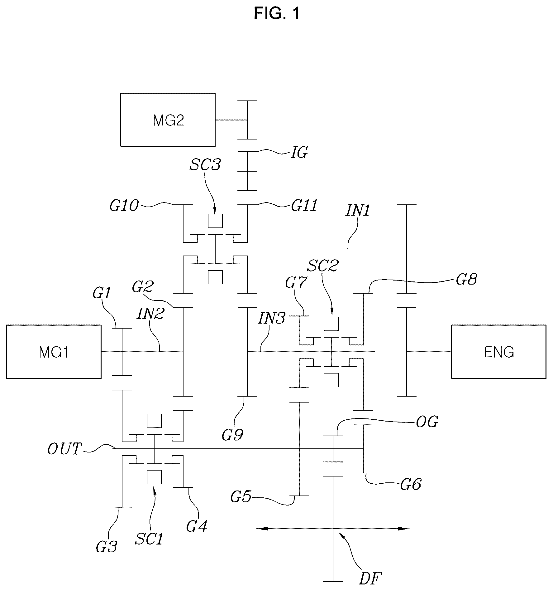
is a view illustrating the structure of a hybrid powertrain for a vehicle according to an embodiment of the present invention;
is a table showing the operating modes of the powertrain shown in ;
is a view illustrating realization of an EV-1 mode in the operating mode table shown in ;
is a view illustrating realization of a Two-EV-1 mode in the operating mode table shown in ;
is a view illustrating realization of a Series-1 mode in the operating mode table shown in ;
is a view illustrating realization of a Series-3 mode in the operating mode table shown in ;
is a view illustrating realization of an HEV1-1 mode in the operating mode table shown in ;
is a view illustrating realization of an HEV2-1 mode in the operating mode table shown in ;
is a view illustrating realization of an HEV3-1 mode in the operating mode table shown in ; and
is a view illustrating realization of an HEV4-2 mode in the operating mode table shown in .
DETAILED DESCRIPTION OF ILLUSTRATIVE EMBODIMENTS
Various exemplary embodiments will now be described more fully with reference to the accompanying drawings, in which only some exemplary embodiments are shown. Specific structural and functional details disclosed herein are merely representative for the purpose of describing exemplary embodiments. The present invention, however, may be embodied in many alternative forms, and should not be construed as being limited to the exemplary embodiments set forth herein.
Accordingly, while exemplary embodiments of the invention are capable of being variously modified and taking alternative forms, embodiments thereof are shown by way of example in the drawings and will herein be described in detail. It should be understood, however, that there is no intent to limit the present invention to the particular exemplary embodiments disclosed. On the contrary, exemplary embodiments are to cover all modifications, equivalents, and alternatives falling within the scope of the invention.
It will be understood that, although the terms “first”, “second”, etc. may be used herein to describe various elements, these elements should not be limited by these terms. These terms are only used to distinguish one element from another. For example, a first element could be termed a second element, and, similarly, a second element could be termed a first element, without departing from the scope of exemplary embodiments of the present invention.
It will be understood that when an element is referred to as being “connected” or “coupled” to another element, it can be directly connected or coupled to the other element, or intervening elements may be present. In contrast, when an element is referred to as being “directly connected” or “directly coupled” to another element, there are no intervening elements present. Other words used to describe the relationship between elements should be interpreted in a like fashion (e.g. “between” versus “directly between”, “adjacent” versus “directly adjacent”, etc.).
The terminology used herein is for the purpose of describing particular embodiments only and is not intended to be limiting of exemplary embodiments of the invention. As used herein, the singular forms “a”, “an”, and “the”, are intended to include the plural forms as well, unless the context clearly indicates otherwise. It will be further understood that the terms “comprises”, “comprising”, “includes”, and/or “including”, when used herein, specify the presence of stated features, integers, steps, operations, elements, components, or combinations thereof, but do not preclude the presence or addition of one or more other features, integers, steps, operations, elements, components, or combinations thereof.
Unless otherwise defined, all terms used herein, which include technical or scientific terms, have the same meanings as those generally appreciated by those skilled in the art. The terms, such as ones defined in common dictionaries, should be interpreted as having the same meanings as terms in the context of pertinent technology, and should not be interpreted as having ideal or excessively formal meanings unless clearly defined in the specification.
Hereinafter, exemplary embodiments of the present invention will be described in detail with reference to the accompanying drawings. In the drawings, the same reference numerals refer to the same components.
Referring to , a hybrid powertrain for a vehicle according to an embodiment of the present invention includes a first input shaft IN 1 , which is mounted so as to be interlocked with an engine ENG, a second input shaft IN 2 , which is interlocked with a first motor MG 1 and is mounted parallel to the first input shaft IN 1 , a third input shaft IN 3 , which is interlocked with a second motor MG 2 and is mounted parallel to the second input shaft IN 2 , an output shaft OUT, which is mounted parallel to the third input shaft IN 3 , a first selective mesh device SC 1 , which is mounted so as to transmit power from the second input shaft IN 2 to the output shaft OUT at multiple different gear ratios, a second selective mesh device SC 2 , which is mounted so as to transmit power from the third input shaft IN 3 to the output shaft OUT at multiple different gear ratios, and a third selective mesh device SC 3 , which is mounted so as to transmit power from the first input shaft IN 1 to the second input shaft IN 2 or the third input shaft IN 3 .
That is, the hybrid powertrain for a vehicle according to embodiments of the present invention is constructed such that the power transmitted from the engine ENG to the first input shaft IN 1 , the power transmitted from the first motor MG 1 to the second input shaft IN 2 , and the power transmitted from the second motor MG 2 to the third input shaft IN 3 are transmitted to the output shaft OUT according to various combinations of meshing shown in , formed by the first selective mesh device SC 1 , the second selective mesh device SC 2 , and the third selective mesh device SC 3 , so as to realize a total of 24 driving modes.
For reference, in , “L” represents the state in which the sleeve of each selective mesh device meshes with a left gear based on , and “R” represents the state in which the sleeve of each selective mesh device meshes with a right gear based on .
A first gear G 1 and a second gear G 2 are mounted on the second input shaft IN 2 so as to be non-rotatable relative to the second input shaft IN 2 , and a third gear G 3 and a fourth gear G 4 are mounted on the output shaft OUT so as to be rotatable relative to the output shaft OUT and to mesh with the first gear G 1 and the second gear G 2 , respectively. The first selective mesh device SC 1 serves to connect one of the third gear G 3 and the fourth gear G 4 to the output shaft OUT.
In other words, as illustrated in the drawings, the first motor MG 1 is directly connected to the second input shaft IN 2 , the first gear G 1 and the second gear G 2 are mounted on the second input shaft IN 2 so as to rotate together therewith, the third gear G 3 meshes with the first gear G 1 , and the fourth gear G 4 meshes with the second gear G 2 . Accordingly, when the first selective mesh device SC 1 connects the third gear G 3 to the output shaft OUT, the power supplied from the first motor MG 1 to the second input shaft IN 2 is transmitted to the output shaft OUT via the first gear G 1 and the third gear G 3 . When the first selective mesh device SC 1 connects the fourth gear G 4 to the output shaft OUT, the power supplied to the second input shaft IN 2 is transmitted to the output shaft OUT via the second gear G 2 and the fourth gear G 4 .
A fifth gear G 5 and a sixth gear G 6 are mounted on the output shaft OUT so as to be non-rotatable relative to the output shaft OUT, and a seventh gear G 7 and an eighth gear G 8 are mounted on the third input shaft IN 3 so as to be rotatable relative to the third input shaft IN 3 and to mesh with the fifth gear G 5 and the sixth gear G 6 , respectively. The second selective mesh device SC 2 serves to connect one of the seventh gear G 7 and the eighth gear G 8 to the third input shaft IN 3 .
In other words, because the seventh gear G 7 meshes with the fifth gear G 5 and the eighth gear G 8 meshes with the sixth gear G 6 , when the second selective mesh device SC 2 connects the seventh gear G 7 to the third input shaft IN 3 , the power supplied to the third input shaft IN 3 is transmitted to the output shaft OUT via the seventh gear G 7 and the fifth gear G 5 , and when the second selective mesh device SC 2 connects the eighth gear G 8 to the third input shaft IN 3 , the power supplied to the input shaft IN 3 is transmitted to the output shaft OUT via the eighth gear G 8 and the sixth gear G 6 .
A ninth gear G 9 is mounted on the third input shaft IN 3 so as to be non-rotatable relative to the third input shaft IN 3 , and a tenth gear G 10 and an eleventh gear G 11 are mounted on the first input shaft IN 1 so as to be rotatable relative to the first input shaft IN 1 and to mesh with the second gear G 2 , which is mounted so as to be non-rotatable relative to the second input shaft IN 2 , and the ninth gear G 9 , respectively. The third selective mesh device SC 3 serves to connect one of the tenth gear G 10 and the eleventh gear G 11 to the first input shaft IN 1 .
In other words, the tenth gear G 10 is mounted on the first input shaft IN 1 so as to be rotatable relative to the first input shaft IN 1 in the state of meshing with the second gear G 2 , and the eleventh gear G 11 is mounted on the first input shaft IN 1 so as to be rotatable relative to the first input shaft IN 1 in the state of meshing with the ninth gear G 9 . Accordingly, when the third selective mesh device SC 3 connects the tenth gear G 10 to the first input shaft IN 1 , the power supplied to the first input shaft IN 1 is transmitted to the second input shaft IN 2 via the tenth gear G 10 and the second gear G 2 . When the third selective mesh device SC 3 connects the eleventh gear G 11 to the first input shaft IN 1 , the power supplied to the first input shaft IN 1 is transmitted to the third input shaft IN 3 via the eleventh gear G 11 and the ninth gear G 9 .
In the embodiment, the third input shaft IN 3 is mounted so as to be interlocked with the second motor MG 2 via the ninth gear G 9 and the eleventh gear G 11 in that order.
In other words, in the embodiment, when the second motor MG 2 drives an idler gear IG, which meshes with the eleventh gear G 11 , the power from the second motor MG 2 is transmitted to the third input shaft IN 3 via the eleventh gear G 11 and the ninth gear G 9 in that order.
The idler gear IG may be provided as shown in the drawings in the case in which there is a need to secure a space between the second motor MG 2 and the third selective mesh device SC 3 or to increase a gear ratio. In another embodiment, however, the idler gear IG may be omitted.
In addition, an output gear OG for outputting power to a differential DF is mounted on the output shaft OUT so as to be non-rotatable relative to the output shaft OUT. Accordingly, the power supplied to the output shaft OUT is transmitted to the left and right drive wheels via the differential DF.
At least one of the first selective mesh device SC 1 , the second selective mesh device SC 2 , or the third selective mesh device SC 3 may be implemented as a dog clutch.
Alternatively, at least one of the first selective mesh device SC 1 , the second selective mesh device SC 2 , or the third selective mesh device SC 3 may be implemented as a synchromesh device.
In other words, as used herein, “selective mesh device” is meant to generally include a dog clutch and a synchromesh device. The synchromesh device may be a device employing a synchromesh-type mechanism in which a synchronizer ring is provided so that a sleeve and a clutch gear mesh with each other while carrying out a synchronizing action using frictional force, unlike a dog clutch.
It is advantageous to employ a dog clutch as the selective mesh device from the aspects of cost and weight, and the synchronizing action required for engagement of the dog clutch may be carried out by controlling the first motor MG 1 or the second motor MG 2 .
The hybrid powertrain for a vehicle according to embodiments of the present invention configured as described above is capable of realizing 24 driving modes shown in , as mentioned above.
In , the term “EV” represents an electric vehicle mode in which only one of the first motor MG 1 and the second motor MG 2 is used to drive the vehicle, the term “Two-EV” represents an electric vehicle mode in which both the first motor MG 1 and the second motor MG 2 are used to drive the vehicle, the term “Series” represents a series mode in which the electric power generated by driving one of the first motor MG 1 and the second motor MG 2 using the power from the engine ENG is used to drive the other motor and the other motor is used to drive the vehicle, and the term “HEV” represents a hybrid mode in which the engine ENG and one of the first motor MG 1 and the second motor MG 2 are used together to drive the vehicle.
For reference, in the HEV mode shown in , the term “UD” represents an underdrive state in which the powertrain realizes a speed reduction ratio, and the term “OD” represents an overdrive state in which the powertrain realizes a speed increasing ratio.
to 10 illustrate states of realizing some representative driving modes among the 24 driving modes shown in . In the drawings, the flow of power is indicated by the arrows, and the sleeve of each of the selective mesh devices is illustrated as being in a neutral state in which the same is located in the middle, a state in which the same is meshed with a gear disposed on the left, or a state in which the same is meshed with a gear disposed on the right.
As is apparent from the above description, a hybrid powertrain for a vehicle according to embodiments of the present invention is capable of realizing various driving modes with a comparatively simple construction, thereby improving the power performance and fuel efficiency of a vehicle. In addition, embodiments of the present invention are capable of preventing interruption of transmission of power when switching between driving modes, thereby providing an improved gear-shifting sensation.
Although the preferred embodiments of the present invention have been disclosed for illustrative purposes, those skilled in the art will appreciate that various modifications, additions and substitutions are possible, without departing from the scope and spirit of the invention as disclosed in the accompanying claims.
Figures (10)
Citations
This patent cites (17)
- US20070243966
- US20090011887
- US20090170649
- US20100062891
- US20100078238
- US20120021861
- US20160144702
- US20170305258
- US20190337376
- US20220153124
- US20220185093
- US20220250462
- US20220252155
- US20220355657
- US102019216213
- US3058696
- US102216067