Abstract
A potting boat adapted to receive a printed circuit board is described. The boning boat includes a base plate and a plurality of sidewalls projecting from the base plate, a plurality of cooling fins, a recessed portion, and an arm. The plurality of cooling fins are formed on one of the sidewalls. The cooling fins extend laterally outward from the one of the sidewalls. The recessed portion is in a first sidewall of the plurality of sidewalls, and extends laterally inward. The arm has a first end fixed to the sidewall and an opposite, second end not connected with the first sidewall. The arm at least partially overlays the recessed portion to define a void within which electrical wires connected to the printed circuit board are retained proximate the first sidewall.
Claims (20)
1. A potting boat adapted to receive a printed circuit board, the potting boat comprising: a base plate and a plurality of sidewalls projecting from the base plate; a plurality of cooling fins formed on one of the sidewalls, the cooling fins extending laterally outward from one of the sidewalls; a recessed portion in a first sidewall of the plurality of sidewalls having a recessed wall portion extending laterally inward from a remaining length of the first sidewall; and an arm having a first end fixed to the first sidewall and an opposite, second end not connected with the first sidewall, the arm at least partially overlying the recessed wall portion to define a void within which electrical wires connected to the printed circuit board are retained proximate the first sidewall.
14. A power tool comprising: an electric motor configured to provide torque to a rotating component in the power tool when activated; a printed circuit board including a plurality of heat-generating electrical components; a potting boat in which the printed circuit board is received, the potting boat including a base plate and a plurality of sidewalls projecting from the base plate; a plurality of cooling fins formed on one of the sidewalls, the cooling fins extending laterally outward from the one of the side walls; a recessed portion in a first sidewall of the plurality of sidewalls having a recessed wall portion extending laterally inward from a remaining length of the first sidewall; and an arm having a first end fixed to the first sidewall and an opposite, second end not connected with the first sidewall, the arm at least partially overlying the recessed wall portion to define a void within which electrical wires connected to the printed circuit board are retained proximate the first sidewall, wherein the electrical wires are routed through the void and over the first sidewall to connect with the printed circuit board.
Show 18 dependent claims
2. The potting boat of claim 1 , wherein the cooling fins are formed on the first sidewall.
3. The potting boat of claim 2 , further comprising a second plurality of cooling fins formed on a second sidewall of the plurality of sidewalls, wherein the second sidewall is located opposite the first sidewall.
4. The potting boat of claim 2 , wherein the recessed wall portion in the first sidewall is a first recessed portion, and wherein the potting boat further comprises a second recessed portion extending laterally inward from another sidewall of the plurality of sidewalls.
5. The potting boat of claim 4 , wherein the second recessed portion is located in a second sidewall that is adjacent the first sidewall, and wherein the second sidewall is devoid of cooling fins.
6. The potting boat of claim 1 , wherein the arm includes an inwardly projecting finger at the second end.
7. The potting boat of claim 6 , wherein a gap between the finger and the first sidewall is less than a height of the void.
8. The potting boat of claim 1 , wherein the base plate defines a closed end of the potting boat and the sidewalls terminate at an open end of the potting boat, and wherein the potting boat further comprises an intermediate surface extending from the closed end to an intermediate position between the open end and the closed end.
9. The potting boat of claim 8 , wherein the base plate includes holes that extend through at least a portion thereof, the holes being configured to receive fasteners to secure the printed circuit board within the potting boat, and wherein the holes extend through at least a portion of the intermediate surface.
10. The potting boat of claim 8 , wherein the intermediate surface includes an edge that is at least one of chamfered or rounded.
11. The potting boat of claim 1 , wherein the base plate includes holes that extend through at least a portion thereof, the holes being configured to receive fasteners to secure the printed circuit board within the potting boat.
12. The potting boat of claim 1 , wherein the arm is tapered between the first end and the second end thereof.
13. The potting boat of claim 12 , wherein the taper is formed on the interior of the arm such that a width of the void between the recessed wall portion and the arm increases along the length of the arm from the first end toward the second end.
15. The power tool of claim 14 , wherein the printed circuit board includes field effect transistors operable to direct electrical current from a power source toward the motor.
16. The power tool of claim 14 , wherein the cooling fins are formed on the first sidewall.
17. The power tool of claim 16 , further comprising a second plurality of cooling fins formed on a second sidewall of the plurality of sidewalls, wherein the second sidewall is located opposite the first sidewall.
18. The power tool of claim 16 , wherein the recessed wall portion in the first sidewall is a first recessed portion, and wherein the potting boat further comprises a second recessed portion extending laterally inward from another sidewall of the plurality of sidewalls.
19. The power tool of claim 14 , wherein the arm includes an inwardly projecting finger at the second end, and wherein a gap between the finger and the first sidewall is less than a height of the void.
20. The power tool of claim 14 , further comprising an outer housing within which the potting boat and the printed circuit board are received.
Full Description
Show full text →
CROSS-REFERENCE TO RELATED APPLICATIONS
This application claims priority to U.S. Provisional Patent Application No. 63/210,094 filed on Jun. 14, 2021, and U.S. Provisional Patent Application No. 63/161,277 filed on Mar. 15, 2021, the entire contents of which are incorporated herein by reference.
FIELD OF THE INVENTION
The present invention relates to power tools, and more particularly to power tools having potting boat heat sinks.
BACKGROUND OF THE INVENTION
Potting boats are typically used to dissipate heat from printed circuit board assemblies in power tools. Such potting boats are made of thermally conductive material to accumulate heat generated by the electrical components for subsequent discharge from the potting boat.
SUMMARY OF THE INVENTION
The invention provides, in one aspect, a potting boat adapted to receive a printed circuit board. The potting boat comprises a base plate and a plurality of walls projecting from the base plate. The potting boat further comprises a plurality of cooling fins formed on one of the sidewalls, the cooling fins extending laterally outward from the one of the sidewalls. The potting boat further comprises a recessed portion in a first sidewall of the plurality of sidewalls, extending laterally inwardly. The potting boat further comprises an arm having a first end fixed to the first sidewall and an opposite, second end not connected with the first sidewall, the arm at least partially overlying the recessed portion to define a void within which the electrical wires are connected to the printed circuit board are retained proximate the first sidewall.
The invention provides, in another independent aspect, a power tool comprising an electric motor configured to provide torque to a rotating component in the power tool when activated, a printed circuit board including a plurality of heat-generating electrical components, and a potting boat in which the printed circuit board is received. The potting boat comprises a comprises a plurality of cooling fins formed on one of the sidewalls, the cooling fins extending laterally outward from the one of the sidewalls. The potting boat further comprises a recessed portion in a first sidewall of the plurality of sidewalls, extending laterally inwardly. The potting boat further comprises an arm having a first end fixed to the first sidewall and an opposite, second end not connected with the first sidewall, the arm at least partially overlying the recessed portion to define a void within which the electrical wires are connected to the printed circuit board are retained proximate the first sidewall. The electrical wires are routed through the void and over the first sidewall to connect with the printed circuit board.
Other features and aspects of the invention will become apparent by consideration of the following detailed description and accompanying drawings.
BRIEF DESCRIPTION OF THE DRAWINGS
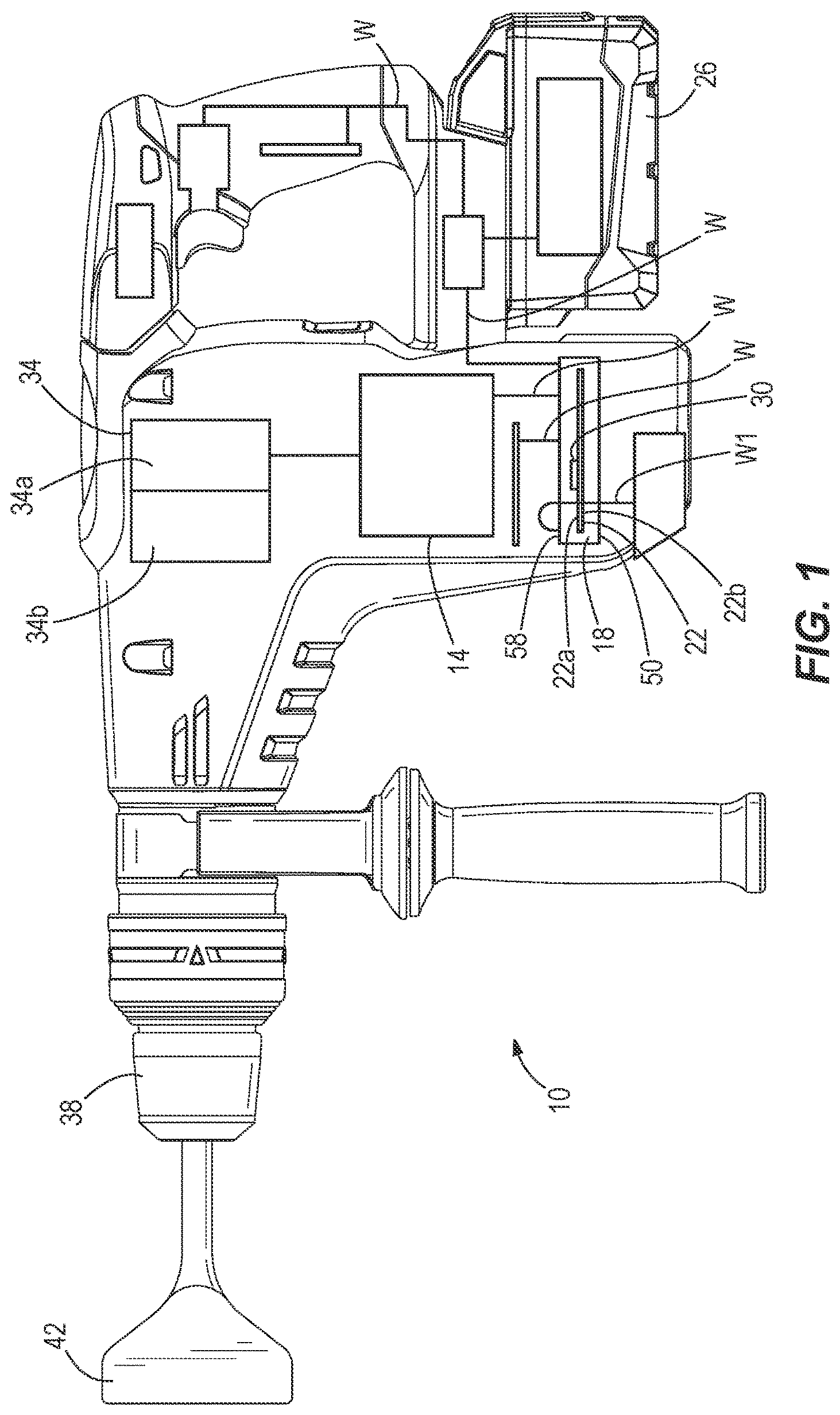
is a side view of a power tool including a potting boat.
is an enlarged side view of an electronics unit of the power tool of .
is a perspective view of the potting boat of .
is a side view of the potting boat of .
is another side view of the potting boat of .
is a top view of the potting boat of .
is a bottom view of the potting boat of .
is a front view of the potting boat of .
is a rear view of the potting boat of .
is a perspective view of the potting boat of with a printed circuit board mounted therein.
is a front view of the potting boat and printed circuit board of .
is a perspective view of an alternate potting boat for use in the power tool of .
Before any embodiments of the invention are explained in detail, it is to be understood that the invention is not limited in its application to the details of construction and the arrangement of components set forth in the following description or illustrated in the following drawings. The invention is capable of other embodiments and of being practiced or of being carried out in various ways. Also, it is to be understood that the phraseology and terminology used herein is for the purpose of description and should not be regarded as limiting.
DETAILED DESCRIPTION
schematically illustrates a power tool (e.g., a rotary hammer 10 ) including a brushless DC electric motor 14 , a gear train 34 a that receives torque from the motor 14 to rotate a spindle 38 , and a reciprocating mechanism 34 b operable to impact axial impacts to a tool bit (e.g., a drill bit) driven by the spindle 38 . The rotary hammer 10 also includes a potting boat 18 in which a printed circuit board (i.e., PCB 22 ) is positioned and an onboard power source (e.g., a battery pack 26 ). Wires W electrically connect the motor 14 , the PCB 22 , and the battery pack 26 . Field effect transistors (i.e., FETs 30 ) are mounted on the PCB 22 and are operable to function as an inverter bridge circuit to direct electrical current from the battery pack 26 to the motor 14 . During use of the rotary hammer 10 , the FETs 30 are rapidly and sequentially switched, which generates heat, to transmit power from the battery pack 26 to the motor 14 . The potting boat 18 is configured as a heat sink to dissipate heat generated by switching of the FETs 30 .
illustrate the potting boat 18 in detail. With reference to , the potting boat 18 includes a base plate 46 , which is generally planar and defines a closed end 50 of the potting boat 18 . Sidewalls 54 a - 54 d project from the base plate 46 and terminate in an open end 58 of the potting boat 18 . As such, the potting boat 18 is shaped generally as a cuboid having an open end 58 . In the illustrated embodiment, there are four sidewalls 54 a - 54 d , and each sidewall extends perpendicular from the base plate 46 to the open end 58 .
As illustrated in , sidewall 54 a and sidewall 54 c are each provided with cooling fins 60 on the exterior surface thereof. In other words, the cooling fins 60 extend laterally outward from the sidewalls 54 a , 54 c . The sidewalls 54 a , 54 c are opposite from each other in the lateral direction. The cooling fins 60 extend laterally outward from the sidewalls 54 a , 54 c between the open end 58 and the closed end 50 . In the illustrated embodiment, the cooling fins 60 axially extend the entire height of the potting boat 18 between the open end 58 and the closed end 50 .
As best illustrated in , the potting boat 18 includes rounded corners 62 between each of the sidewalls 54 a - 54 d . The corners 62 are rounded at the interfaces between each of the sidewalls 54 a - 54 d in a planar direction parallel with the base plate 46 .
As illustrated in , the potting boat 18 includes an intermediate surface 66 extending from the closed end 50 to an intermediate position between the open end 58 and the closed end 50 . The intermediate surface 66 is in the form of a generally planar plateau that projects from the base plate 46 towards the open end 58 . In the illustrated embodiment, the plate 46 is generally planar to facilitate the flow of potting material beneath the PCB 22 in directions parallel to the planar plate 46 . Other embodiments may include another void or a different height intermediate surface 66 (i.e., separate faces) projecting from the plate 46 . This may further assist flow of potting material in assembly of the PCB 22 with the potting boat 18 . The depth of the plate 46 is deep enough to provide enough clearance from through-hole components and/or wire solder joints to mitigate electrical shorts between the PCB 22 , or any terminals or wires extending from the PCB 22 with the potting boat 18 . In the illustrated embodiment, the intermediate surface 66 only extends over a portion of the base plate 46 such that a portion of the interior depth of the potting boat 18 extends from the base plate 46 to the open end 58 , and another portion of the potting boat 18 extends from the intermediate surface 66 to the open end 58 . The illustrated potting boat 18 includes a plurality of intermediate surfaces 66 which are separated (i.e., non-contiguous) from each other. The intermediate surfaces 66 are also generally planar such that when the PCB 22 is located within the potting boat 18 , efficient thermal transfer is achieved between the PCB 22 and the potting boat 18 . Finally, as illustrated in at least , the intermediate surfaces 66 may further include chamfered or rounded edges E to avoid wear or abrasion on the wires extending from the PCB 22 that may otherwise cause electrical shorts with the potting boat 18 .
Returning to , the sidewalls 54 a , 54 b of the potting boat 18 include respective recessed portions 70 a , 70 b . The recessed portion 70 a of the sidewall 54 a extends laterally inward from the remaining length of the sidewall 54 a . The recessed portion 70 a spans a length L 1 in a direction between the sidewall 54 b and the sidewall 54 d and a width W′ in a direction between the sidewall 54 a and the sidewall 54 c . The recessed portion 70 b of the sidewall 54 b extends inward from the remaining length of the sidewall 54 b . The recessed portion 70 b spans a length L 2 in a direction between the sidewall 54 a and the sidewall 54 c and a width W″ in a direction between the sidewall 54 b and the sidewall 54 c . Each of the recessed portions 70 a , 70 b of the potting boat 18 extend from the open end 58 to the closed end 50 .
With continued reference to , an arm 74 (e.g., a cantilevered arm) is located adjacent the recessed portion 70 a of the sidewall 54 a . The arm 74 includes a first end 74 a (i.e., a fixed end) connected to the sidewall 54 a and a second end 74 b (i.e., a free end) opposite the first end 74 a . The arm 74 spans between the first end 74 a and the second end 74 b and has a length L 3 that is less than the length L 1 of the recessed portion 70 a of the sidewall 54 a . The length L 3 of the arm 74 is measured parallel to the sidewalls 54 a , 54 c between the first end 74 a and the second end 74 b . A gap G 1 extending parallel with the sidewalls 54 a , 54 c is defined between the second end 74 b of the arm 74 and the recessed portion 70 a . A gap G 2 is defined between the arm 74 and the recessed portion 70 a . The gap G 2 extends parallel with the sidewalls 54 b , 54 d and opens into a void V defined by a combination of the closed end 58 , the open end 50 , the recessed portion 70 a , and the arm 74 . In some embodiments of the potting boat 14 , the arm 74 has a finger 78 ( ) at the second end 74 b thereof. The finger 78 projects inwardly from the second end 74 b towards the recessed portion 70 a and the sidewall 54 c in a direction parallel with the sidewalls 54 b , 54 d . The gap G 2 is formed as the length L 3 of the arm 74 is less than a length L 1 of the recessed portion 70 a.
With continued reference to , the potting boat 18 includes holes 82 . In the illustrated embodiment, the holes 82 extend through the entire thickness of the base plate 46 of the potting boat 18 . As illustrated in , the holes 82 are configured to receive fasteners 86 (e.g., screws) to secure the PCB 22 within the potting boat 18 . The holes 82 are optionally located at locations corresponding with intermediate surfaces 66 of the potting boat 18 . As the intermediate surfaces 66 are generally planar, when the PCB 22 is secured to the potting boat 18 via the fasteners 86 , any unintended strain imparted to the PCB 22 (e.g., as a result of the PCB 22 bending from being mounted to a non-planar surface) via the fasteners 86 is mitigated. Further, other types of fasteners 86 besides screws may be employed to secure the PCB 22 to the potting boat 18 . For example, other such fasteners may temporarily hold the PCB 22 against the potting boat 18 while the PCB 22 is potted and until the potting material has cured. Such temporary fasteners may provide mechanical support to the electrical components (e.g., the FETs 30 ) of the PCB 22 during the potting process, until the potting material has cured at which time the cured potting material itself can primarily support the electrical components. The PCB 22 includes a first surface 22 a ( ) onto which the FETs 30 are mounted. The wires W engage (i.e., are soldered or otherwise connected to) the PCB 22 at the first surface 22 a thereof. The PCB 22 includes an opposite second surface 22 b ( ) onto which other electrical components are mounted. The other electrical components may be nested between the intermediate surface 66 and the base plate 46 . As illustrated in , in the illustrated embodiment, the electrical components (e.g., the FETs 30 ) are mounted upon the first surface 22 a of the PCB 22 . The first surface 22 a faces the open end 58 of the potting boat 18 .
As best illustrated in , a subset of wires W 1 extends from the PCB 22 , project from the open end 58 of the potting boat 18 , extend through the void V, and extend beyond the closed end 50 . Other wires W of the power tool 10 are connected to the PCB 22 through the open end 58 of the potting boat 18 without passing through the void V.
With continued reference to , a combination of the void V, the arm 74 , and the finger 78 define a wire guide 80 through which the wires W 1 pass and in which the wires W 1 are retained. As the potting boat 18 includes the wire guide 80 , separate elements (e.g., wire ties, etc.) are not required to tether the wires W 1 together as they pass from the open end 58 of the potting boat 18 toward the closed end 50 . In the power tool 10 , the wire guide 80 provides space between the sidewall 54 a and in interior surface of the outer housing 12 ( ) of the power tool 10 through which the wires W 1 may be routed to connect with electrical components beneath (i.e., beyond the closed end 50 of) the potting boat 18 . The arm 74 is rigid to prevent the wires W 1 within the wire guide 80 from being pinched or otherwise damaged in response to an impact on the outer housing 12 of the power tool 10 . In other words, the wire guide 80 nests or secures the wires W 1 with the potting boat 18 as they extend from the open end 58 , through the void V, and beyond the closed end 50 , thereby circumventing the need for additional guide structure for the wires W 1 within the power tool 10 . Additionally, the recessed portion 70 b also provides space between the sidewall 54 b and the interior surface of the outer housing 12 of the power tool 10 through which other wires W may pass or extend through in the same manner as the wire guide 80 .
The illustrated potting boat 18 is made using a die cast process. The illustrated potting boat 18 is made of aluminum, which has relatively high thermal conductivity on the order of around 200 W/m-K, or an aluminum alloy. The high thermal conductivity of the potting boat 18 increases the rate at which accumulated heat from the PCB 22 can be transferred away from the PCB 22 , into the potting boat 18 , and to the environment via the cooling fins 60 .
illustrates an alternate potting boat 18 ′ for use with the rotary hammer 10 of . The potting boat 18 ′ generally shares the same features as in the potting boat 18 . However, the arm 74 in the potting boat 18 ′ is tapered between the first end 74 a and the second end 74 b . In the illustrated embodiment of the potting boat 18 ′, the taper is formed on the interior of the arm 74 such that the width of the void V increases along the length of the arm 74 , from the first end 74 a toward the second end 74 b . The potting boat 18 ′ does not have a finger 78 as described above with respect to the potting boat 18 . Additionally, the potting boat 18 ′ does not have the recessed portion 70 b on the sidewall 54 b . The potting boat 18 ′ has the intermediate surface 66 located at different portions of the base plate 46 than the potting boat 18 . The potting boat 18 ′ also has a plurality of intermediate surfaces 66 which are separated (i.e., non-continuous) from each other. Finally, the cooling fins 60 of the potting boat 18 ′ have a cross-sectional profile that is scalloped, as opposed to the generally rectangular cross-sectional profile of the cooling fins 60 of the potting boat 18 .
Various features of the invention are set forth in the following claims.
Figures (6)
Citations
This patent cites (61)
- US4707763
- US5060114
- US6154369
- US6185101
- US6418021
- US6731503
- US6840496
- US6845961
- US6920047
- US7106593
- US7209360
- US7417841
- US8092932
- US8107207
- US8107208
- US8168896
- US8803452
- US8821778
- US9154009
- US9318932
- US9450472
- US9480185
- US9510438
- US9674976
- US9812930
- US9819241
- US9847194
- US10043619
- US10056806
- US10098261
- US10326337
- US20030112602
- US20060120054
- US20070099073
- US20080113262
- US20090057006
- US20100108341
- US20110008655
- US20120155028
- US20130342041
- US20150280516
- US20150282337
- US20160020676
- US20180034346
- US20180041088
- US20180083510
- US20180084646
- US20180184538
- US20180294688
- US20180323681
- US20180352671
- US20190044415
- US20190291260
- US20200274421
- US20220247280
- US20220271624
- US10205818
- US2007063310
- US102017202431
- US2009083315
- US2018053873