Abstract
A bearing apparatus includes a bearing that rotatably supports a main spindle around a rotation axis, a spacer including an inner-ring spacer adjacent to an inner ring of the bearing and an outer-ring spacer adjacent to an outer ring, and a heat flux sensor provided in an inside surface of the outer-ring spacer. A distance in a direction along the rotation axis from a center of the bearing to a center of the heat flux sensor is longer than 0.5 time and shorter than one time of a dimension of the bearing in the direction along the rotation axis.
Claims (8)
1. A bearing apparatus comprising: a bearing including an inner ring, an outer ring, a rolling element, and a retainer, the bearing rotatably supporting a rotating body around a rotation axis; a spacer including an inner-ring spacer adjacent to the inner ring and an outer-ring spacer adjacent to the outer ring; and a heat flux sensor provided in one of the spacer and a component around the bearing, wherein a distance in a direction along the rotation axis from a center of the bearing to a center of the heat flux sensor is longer than 0.5 time and shorter than one time of a dimension of the bearing in the direction along the rotation axis.
7. A bearing apparatus comprising: a bearing including an inner ring, an outer ring, a rolling element, and a retainer, the bearing rotatably supporting a rotating body around a rotation axis; a spacer including an inner-ring spacer adjacent to the inner ring and an outer-ring spacer adjacent to the outer ring; and a heat flux sensor provided in one of the spacer and a component around the bearing, wherein a distance in a radial direction of the rotation axis from an outside surface of the inner-ring spacer to the heat flux sensor is equal to or shorter than 25% of a distance between an inside surface of the inner-ring spacer and an outside surface of the outer-ring spacer.
8. A bearing apparatus comprising: a bearing including an inner ring, an outer ring, a rolling element, and a retainer, the bearing rotatably supporting a rotating body around a rotation axis; a spacer including an inner-ring spacer adjacent to the inner ring and an outer-ring spacer adjacent to the outer ring; and a heat flux sensor provided in one of the spacer and a component around the bearing, wherein the heat flux sensor is provided in an inside surface of the outer-ring spacer, the outer-ring spacer is provided with an exhaust port for exhaust of air-oil for lubrication, and a magnitude of an angle in a circumferential direction of the rotation axis from a center of the exhaust port to a center of the heat flux sensor is smaller than 90°.
Show 5 dependent claims
2. The bearing apparatus according to claim 1 , wherein a distance in a radial direction of the rotation axis from an outside surface of the inner-ring spacer to the heat flux sensor is equal to or shorter than 25% of a distance between an inside surface of the inner-ring spacer and an outside surface of the outer-ring spacer.
3. The bearing apparatus according to claim 1 , wherein the heat flux sensor is provided in an inside surface of the outer-ring spacer, the outer-ring spacer is provided with an exhaust port for exhaust of air-oil for lubrication, and magnitude of an angle in a circumferential direction of the rotation axis from a center of the exhaust port to the center of the heat flux sensor is smaller than 90°.
4. The bearing apparatus according to claim 3 , wherein the outer-ring spacer is provided with a nozzle that injects the air-oil, and the nozzle is provided in a region in the outer-ring spacer opposite to the exhaust port.
5. The bearing apparatus according to claim 1 , wherein the outer-ring spacer is provided with a cooling medium flow channel.
6. The bearing apparatus according to claim 1 , wherein the rotating body is a main spindle of a machine tool.
Full Description
Show full text →
CROSS-REFERENCE OF RELATED APPLICATIONS
This application is the U.S. National Phase under 35 U.S.C. § 371 of International Patent Application No. PCT/JP2021/032960, filed on Sep. 8, 2021, which in turn claims the benefit of Japanese Patent Application No. 2020-155151, filed on Sep. 16, 2020, the entire disclosures of which Applications are incorporated by reference herein.
TECHNICAL FIELD
This invention relates to a bearing apparatus that rotatably supports a main spindle or the like of a machine tool.
BACKGROUND ART
A bearing for a main spindle of a machine tool is often used at a high speed and under low load, and an angular contact ball bearing is widely employed for such a bearing. The bearing for the main spindle of the machine tool is lubricated by air-oil (oil-mist) lubrication or grease lubrication. Air-oil lubrication is characterized in ability to maintain a stable lubricated state for a long period of time because of external supply of lubricating oil. Grease lubrication is characterized in excellent cost efficiency because of requirement of neither of an annexed facility and a pipe and in environmental friendliness because of an extremely small amount of generation of mist.
A bearing used in a higher-speed region such as a region where a dn value calculated by multiplying an inner diameter of an inner ring by the number of rotations is equal to or larger than one million as in a main spindle of a machining center among machine tools should operate in a more stable manner. For various factors described below, however, the bearing may undergo surface roughening or peeling at a bearing raceway surface or abnormality of a retainer, and thereafter a temperature of the bearing may excessively increase.
•
• Inappropriate feed and drain of lubricating oil in air-oil lubrication (excessively small or large amount of oil or insufficient exhaust) • Deterioration of lubricating grease sealed in bearing • Entry of coolant or water or a foreign matter into a bearing rolling portion • Oil film rupture due to excessive preload, that is, increase in contact pressure in rolling portion
In order to prevent excessive temperature increase in the bearing due to the above factors, Japanese Patent Laying-Open No. 2017-26078 (PTL 1) discloses such a technique that a lubricating oil feed pump and a contactless temperature sensor are contained in a spacer adjacent to a bearing and the lubricating oil feed pump feeds lubricating oil to the inside of the bearing in accordance with a temperature value of a bearing lubricated portion measured by the temperature sensor.
For example, Japanese Patent Laying Open No. 2016-166832 (PTL 2) discloses a heat flux sensor that senses a heat flux generated by a temperature difference between a front side and a rear side of the sensor, rather than change in temperature. The heat flux sensor is characterized in higher sensitivity and higher reaction speed of a sensor output than a temperature sensor (a contactless temperature sensor or a thermocouple) used in measurement of a temperature of inner and outer rings of a bearing.
CITATION LIST
Patent Literature
•
• PTL 1: Japanese Patent Laying-Open No. 2017-26078 • PTL 2: Japanese Patent Laying Open No. 2016-166832
SUMMARY OF INVENTION
Technical Problem
In a bearing, under the influence by an air curtain produced by rotation of the bearing or the influence by compressed air injected from a nozzle for air-oil lubrication, a flow of air in the bearing may become great. Therefore, when change in temperature in the inside of the bearing is to be sensed in an early stage with the use of a heat flux sensor, depending on a position of the heat flux sensor, there is a concern about lowering in sensitivity of the heat flux sensor.
The present invention was made to solve the problem above, and an object thereof is to achieve high sensitivity of a heat flux sensor contained in a bearing apparatus even in an environment where a flow of air in a bearing is varied by rotation of the bearing or injection of air-oil.
Solution to Problem
•
• (1) A bearing apparatus according to the present disclosure includes a bearing including an inner ring, an outer ring, a rolling element, and a retainer, the bearing rotatably supporting a rotating body around a rotation axis, a spacer including an inner-ring spacer adjacent to the inner ring and an outer-ring spacer adjacent to the outer ring, and a heat flux sensor provided in one of the spacer and a component around the bearing. A distance in a direction along the rotation axis from a center of the bearing to a center of the heat flux sensor is longer than 0.5 time and shorter than one time of a dimension of the bearing in the direction along the rotation axis. • (2) In one aspect, a distance in a radial direction of the rotation axis from an outside surface of the inner-ring spacer to the heat flux sensor is equal to or shorter than 25% of a distance between an inside surface of the inner-ring spacer and an outside surface of the outer-ring spacer. • (3) In one aspect, the heat flux sensor is provided in an inside surface of the outer-ring spacer. The outer-ring spacer is provided with an exhaust port for exhaust of air-oil for lubrication. Magnitude of an angle in a circumferential direction of the rotation axis from a center of the exhaust port to the center of the heat flux sensor is smaller than 90°. • (4) In one aspect, the outer-ring spacer is provided with a nozzle that injects the air-oil. The nozzle is provided in a region in the outer-ring spacer opposite to the exhaust port. • (5) Another bearing apparatus according to the present disclosure includes a bearing including an inner ring, an outer ring, a rolling element, and a retainer, the bearing rotatably supporting a rotating body around a rotation axis, a spacer including an inner-ring spacer adjacent to the inner ring and an outer-ring spacer adjacent to the outer ring, and a heat flux sensor provided in one of the spacer and a component around the bearing. A distance in a radial direction of the rotation axis from an outside surface of the inner-ring spacer to the heat flux sensor is equal to or shorter than 25% of a distance between an inside surface of the inner-ring spacer and an outside surface of the outer-ring spacer. • (6) Another bearing apparatus according to the present disclosure includes a bearing including an inner ring, an outer ring, a rolling element, and a retainer, the bearing rotatably supporting a rotating body around a rotation axis, a spacer including an inner-ring spacer adjacent to the inner ring and an outer-ring spacer adjacent to the outer ring, and a heat flux sensor provided in one of the spacer and a component around the bearing. The heat flux sensor is provided in an inside surface of the outer-ring spacer. The outer-ring spacer is provided with an exhaust port for exhaust of air-oil for lubrication. Magnitude of an angle in a circumferential direction of the rotation axis from a center of the exhaust port to a center of the heat flux sensor is smaller than 90°. • (7) In one aspect, the outer-ring spacer is provided with a cooling medium flow channel. • (8) In one aspect, the rotating body is a main spindle of a machine tool.
Advantageous Effects of Invention
According to this construction, even in an environment where a flow of air in a bearing is varied by rotation of the bearing or injection of air-oil, sensitivity of a heat flux sensor contained in a bearing apparatus can be high.
BRIEF DESCRIPTION OF DRAWINGS
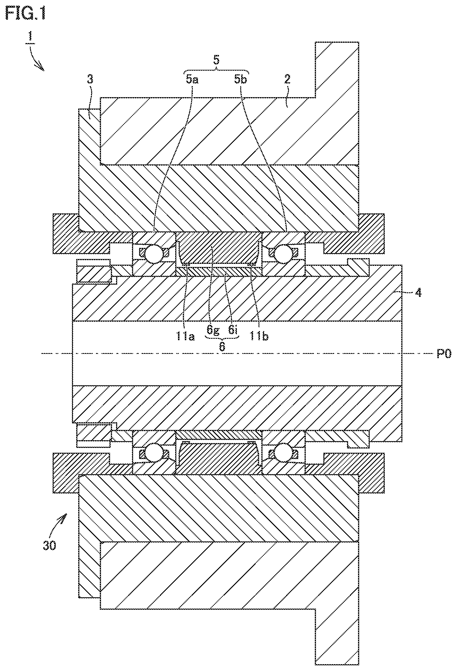
is a cross-sectional view showing a schematic construction of a spindle apparatus in which a bearing apparatus is incorporated.
is a schematic cross-sectional view showing a construction of the bearing apparatus.
is a diagram showing relation among a heat flux, a temperature, and a rotation speed obtained in an acceleration and slowdown test.
is a diagram showing exemplary arrangement when arrangement in an axial direction of a heat flux sensor is varied.
is a diagram showing a condition in a bearing abnormality simulation test.
is a diagram showing relation between arrangement in an axial direction of each heat flux sensor and output sensitivity of each heat flux sensor.
is a diagram showing exemplary arrangement in a radial direction of the heat flux sensor.
is a diagram (No. 1) showing exemplary arrangement of the heat flux sensor.
is a diagram (No. 2) showing exemplary arrangement of the heat flux sensor.
shows relation between arrangement in the radial direction of each heat flux sensor and output sensitivity of each heat flux sensor.
is a diagram showing exemplary arrangement in a circumferential direction of the heat flux sensor.
is a diagram showing exemplary arrangement when arrangement in the circumferential direction of the heat flux sensor is varied.
shows relation between arrangement in the circumferential direction of each heat flux sensor and output sensitivity of each heat flux sensor.
is a diagram showing an exemplary cooling structure provided in an outer-ring spacer.
is a cross-sectional view along XV-XV in .
is a diagram showing a modification of arrangement of the heat flux sensor.
is a diagram showing another modification of arrangement of the heat flux sensor.
DESCRIPTION OF EMBODIMENTS
An embodiment of the present invention will be described below with reference to the drawings. The same or corresponding elements in the drawings below have the same reference characters allotted and description thereof will not be repeated.
is a cross-sectional view showing a schematic construction of a spindle apparatus 1 in which a bearing apparatus 30 according to the present embodiment is incorporated is a schematic cross-sectional view showing a construction of bearing apparatus 30 according to the present embodiment.
Spindle apparatus 1 shown in is used, for example, as a built-in motor type spindle apparatus of a machine tool. In this case, a not-shown motor is incorporated on one end side (left side in ) of a main spindle 4 which is a rotating body supported by spindle apparatus 1 for a main spindle of a machine tool, and a not-shown cutting tool such as an end mill is connected to the other end side (right side in ).
Spindle apparatus 1 includes a bearing 5 including two bearings 5 a and 5 b , a spacer 6 arranged adjacently to bearings 5 a and 5 b , and heat flux sensors 11 a and 11 b . Main spindle 4 is supported rotatably around a rotation axis P 0 by two bearings 5 a and 5 b provided in a housing 3 embedded in an inside portion of a bearing jacket 2 . Bearing 5 a includes an inner ring 5 ia , an outer ring 5 ga , a rolling element Ta, and a retainer Rta. Bearing 5 b includes an inner ring 5 ib , an outer ring 5 gb , a rolling element Tb, and a retainer Rtb. Spacer 6 includes an inner-ring spacer 6 i and an outer-ring spacer 6 g.
Inner ring 5 ia of bearing 5 a and inner ring 5 ib of bearing 5 b that are distant in an axial direction (a direction along rotation axis P 0 ) are fitted to main spindle 4 by interference fit (press-fitting). Inner-ring spacer 6 i is arranged between inner rings 5 ia and 5 ib and outer-ring spacer 6 g is arranged between outer rings 5 ga and 5 gb.
Bearing 5 a is a rolling bearing in which a plurality of rolling elements Ta are arranged between inner ring 5 ia and outer ring 5 ga . Intervals between rolling elements Ta are held by retainer Rta. Bearing 5 b is a rolling bearing in which a plurality of rolling elements Tb are arranged between inner ring 5 ib and outer ring 5 gb . Intervals between rolling elements Tb are held by retainer Rtb.
An angular contact ball bearing, a deep groove ball bearing, or a tapered roller bearing can be employed as bearings 5 a and 5 b . The angular contact ball bearing is included in bearing apparatus 30 shown in , where two bearings 5 a and 5 b are provided in back-to-back duplex bearing (DB) arrangement. Arrangement of the bearing is not limited to back-to-back duplex bearing arrangement, and for example, face-to-face duplex bearing arrangement may be applicable.
Though a structure in which two bearings 5 a and 5 b support main spindle 4 is illustrated and described, a structure in which three or more bearings support main spindle 4 may be applicable.
A not-shown cooling medium flow channel is provided in the inside of housing 3 . By feeding a cooling medium through the cooling medium flow channel in housing 3 , bearings 5 a and 5 b can be cooled.
In spindle apparatus 1 according to the present embodiment, as shown in , lubricating oil supply paths 67 a and 67 b for injecting lubricating oil to bearings 5 a and 5 b for cooling and lubrication of bearings 5 a and 5 b are provided in outer-ring spacer 6 g . Lubricating oil is injected in a state of air-oil or oil mist together with air that carries lubricating oil from a nozzle (which will also simply be referred to as a “lubrication nozzle” below) provided at each of tip ends of lubricating oil supply paths 67 a and 67 b.
Though shows lubricating oil supply paths 67 a and 67 b (lubrication nozzles) at positions proximate to respective heat flux sensors 11 a and 11 b , lubricating oil supply paths 67 a and 67 b are actually arranged at positions displaced in a circumferential direction from heat flux sensors 11 a and 11 b (see which will be described later) does not show lubricating oil supply paths 67 a and 67 h for the sake of brevity.
Heat flux sensors 11 a and 11 b that measure a heat flux are fixed to an inside surface 6 g A of outer-ring spacer 6 g and are opposed to an outside surface 6 i A of inner-ring spacer 6 i . The heat flux refers to a quantity of heat that passes through a unit area per unit time.
Each of heat flux sensors 11 a and 11 b is a sensor that converts a heat flux into an electrical signal based on a Seebeck effect, and an output voltage is generated from a slight temperature difference between a front side and a rear side of the sensor. Heat flux sensors 11 a and 11 b are each more sensitive to variation in heat in the inside of the bearing than a temperature sensor such as a contactless temperature sensor or a thermocouple, and they timely follow variation in heat in the inside of the bearing.
Heat flux sensor 11 a is arranged in inside surface 6 g A of outer-ring spacer 6 g , at an end on a side of bearing 5 a in an axial direction. Heat flux sensor 11 b is arranged in inside surface 6 g A of outer-ring spacer 6 g , at an end on a side of bearing 5 b in the axial direction. Since heat flux sensors 11 a and 11 b are thus provided in the vicinity of respective bearings 5 a and 5 b in outer-ring spacer 6 g , heat flux sensors 11 a and 11 b can directly detect a heat flux of heat that flows between the inner ring and the outer ring of bearings 5 a and 5 b . Arrangement of heat flux sensors 11 a and 11 b will be described later in detail.
In an attempt to measure a temperature of inner rings 5 ia and 5 ib , outer rings 5 ga and 5 gb , and spacer 6 for detecting a sign of seizure of bearings 5 a and 5 b , in spite of abrupt heat generation, the sign may not be detected in an early stage because of delay in increase in temperature.
In contrast, in the present embodiment, the sign of seizure of bearings 5 a and 5 b can be detected based on outputs from heat flux sensors 11 a and 11 b . By using the outputs from heat flux sensors 11 a and 11 b , abrupt heat generation can quickly be detected because heat flux starts to change earlier than the temperature.
Wires (not shown) for sending detection signals to a control device (not shown) are connected to respective heat flux sensors 11 a and 11 b.
<Acceleration and Slowdown Test>
The present applicant conducted an acceleration and slowdown test, in which the bearing apparatus according to the embodiment was incorporated in a tester simulating a main spindle of a machine tool and relation among a heat flux, a temperature, and a rotation speed at the time when the rotation speed of main spindle 4 was increased and decreased was evaluated.
is a diagram showing relation among a heat flux, a temperature, and a rotation speed obtained in an acceleration and slowdown test. As shown in , an output (heat flux) from the heat flux sensor is higher in responsiveness to increase and decrease in rotation speed than an output (temperature of the bearing) from the temperature sensor, and accuracy in detection of a sign of abnormality of the bearing may be improved. Timing of start of increase and decrease in output from the heat flux sensor is substantially synchronous with timing of start of increase and decrease in rotation speed.
In bearings 5 a and 5 b , under the influence by an air curtain produced by rotation of bearings 5 a and 5 b with rotation of main spindle 4 and influence by compressed air injected from the lubrication nozzle, a flow of air may become great. Therefore, depending on positions of heat flux sensors 11 a and 11 b , there is a concern about lowering in sensitivity of heat flux sensors 11 a and 11 b by being affected by the flow of air in bearings 5 a and 5 b.
When a difference in temperature between the front side and the rear side of heat flux sensors 11 a and 11 b is small as well, sensitivity of heat flux sensors 11 a and 11 b may be lowered. For example, in spindle apparatus 1 according to the present embodiment, bearings 5 a and 5 b can be cooled by feed of a cooling medium through the cooling medium flow channel in the inside of housing 3 . When cooling is insufficient, however, the temperature difference between the inner ring and the outer ring of bearings 5 a and 5 b is less likely to be produced. Consequently, the temperature difference between the front side and the rear side of heat flux sensors 11 a and 11 b also becomes small and there is a concern about lowering in sensitivity of heat flux sensors 11 a and 11 b.
In view of aspects above, in the present embodiment, arrangement of heat flux sensors 11 a and 11 b is optimized in outer-ring spacer 6 g so as to improve sensitivity of heat flux sensors 11 a and 11 b even in an environment where a flow of air in bearings 5 a and 5 b is varied by rotation of bearings 5 a and 5 b or injection of compressed air (air-oil) from the lubrication nozzle.
Furthermore, in the present embodiment, by providing a cooling structure not only in the inside of housing 3 but also in outer-ring spacer 6 g where heat flux sensors 11 a and 11 b are arranged, surfaces (surfaces in contact with outer-ring spacer 6 g ) of heat flux sensors 11 a and 11 b opposite to surfaces on the side of main spindle 4 are positively cooled. Thus, when abrupt heat generation occurs in bearings 5 a and 5 b as in burning of bearings 5 a and 5 b , the temperature difference between the front side and the rear side of heat flux sensors 11 a and 11 b becomes greater and that abrupt heat generation can be detected early by heat flux sensors 11 a and 11 b.
Arrangement of heat flux sensors 11 a and 11 b and the cooling structure in outer-ring spacer 6 g will be described below in detail.
<Arrangement in Axial Direction of Heat Flux Sensor>
described above shows exemplary arrangement in the axial direction (the direction along rotation axis P 0 ) of heat flux sensors 11 a and 11 b according to the present embodiment. Heat flux sensor 11 a according to the present embodiment is arranged at a position where a relational expression (1) below is satisfied. B/ 2< L<M (1) where “B” represents a dimension of a width (a length in the axial direction) of bearing 5 a , “L” represents a distance from the center of bearing 5 a to the center of heat flux sensor 11 a , and “M” represents a dimension of a width (a length in the axial direction) of outer-ring spacer 6 g.
Furthermore, heat flux sensor 11 a according to the present embodiment is arranged at a position where a relational expression (2) below is satisfied. B/ 2< L<B (2)
The relational expression (2) is the same as the relational expression (1) with “M” being replaced with “B”.
is a diagram showing exemplary arrangement when arrangement in the axial direction of heat flux sensor 11 a is varied. Specifically, shows a heat flux sensor 11 a 1 arranged at a position where distance L from the center of bearing 5 a is set to a “prescribed value L1,” a heat flux sensor 11 a 2 arranged at a position where distance L from the center of bearing 5 a is set to a “prescribed value L2,” and a heat flux sensor 11 a 3 arranged at a position where distance L from the center of bearing 5 a is set to a “prescribed value L3.”
Prescribed value L1 satisfies a condition of L1 s B/2 and the relational expressions (1) and (2) are not satisfied Prescribed value L2 satisfies a condition of B/2<L2<B, and the relational expressions (1) and (2) are satisfied. Prescribed value L3 satisfies a condition of L3% B, and the relational expression (1) is satisfied but the relational expression (2) is not satisfied.
The present applicant conducted a bearing abnormality occurrence simulation test in an attempt to check output sensitivity of each of heat flux sensors 11 a 1 to 11 a 3 shown in . shows a condition in a bearing abnormality simulation test. In the present simulation test, by introducing a very small amount of lubricating oil into the rolling bearing only at the time of assembly of the main spindle, a situation where abnormality was likely to occur in a tested bearing was created.
is a diagram showing relation between arrangement in the axial direction (distances L1 to L3 from the center of bearing 5 a ) of each heat flux sensor and output sensitivity of each heat flux sensor that is obtained in the simulation test conducted under the test condition shown in .
As shown in , regarding heat flux sensor 11 a 1 of which distance L1 from the center of bearing 5 a satisfies the condition of L1 B/2, the relational expressions (1) and (2) are not satisfied and this heat flux sensor is poorest in output sensitivity. This may be because heat flux sensor 11 a 1 is most affected by air injected from the lubrication nozzle and the air curtain produced by high-speed rotation of bearings 5 a and 5 b and hence lowering in sensitivity of heat flux sensor 11 a 1 is greatest.
Regarding heat flux sensor 11 a 3 of which distance L3 from the center of bearing 5 a satisfies the condition of L3≥B, the relational expression (1) is satisfied but the relational expression (2) is not satisfied, and the heat flux sensor is slightly poor in output sensitivity. This may be because the heat flux sensor is least likely to be affected by air injected from the lubrication nozzle and the air curtain produced by high-speed rotation of bearings 5 a and 5 b , however, it is most distant from bearing 5 a and heat from bearing 5 a is least likely to conduct thereto.
In contrast, regarding heat flux sensor 11 a 2 of which distance L2 from the center of bearing 5 a satisfies the condition of B/2<L2<B, the relational expressions (1) and (2) are satisfied and the heat flux sensor is highest in output sensitivity. This may be because the heat flux sensor is less likely to be affected by air injected from the lubrication nozzle and the air curtain produced by high-speed rotation of bearings 5 a and 5 b , and it is also close to bearing 5 a and hence able to detect heat generation in bearing 5 a earliest (with highest sensitivity).
Heat flux sensor 11 a according to the present embodiment is arranged at a position where the relational expressions (1) and (2) described above are satisfied. Therefore, even in an environment where the flow of air in bearing 5 a is varied by rotation of bearing 5 a or injection from the lubrication nozzle, sensitivity of heat flux sensor 11 a can be high.
Heat flux sensor 11 b according to the present embodiment is also arranged at a position where the relational expressions (1) and (2) described above are satisfied. Therefore, sensitivity of heat flux sensor 11 b can also be high. When the relational expressions (1) and (2) described above are applied to heat flux sensor 11 b , “B” represents a dimension of a width (a length in the axial direction) of bearing 5 b and “L” represents a distance from the center of bearing 5 b to the center of heat flux sensor 11 b.
<Arrangement in Radial Direction of Heat Flux Sensor>
is a diagram showing exemplary arrangement in a radial direction (a radial direction of rotation axis P 0 ) of heat flux sensor 11 b . is a partially enlarged view showing details of a C portion in .
Heat flux sensor 11 b according to the present embodiment is arranged at a position where a relational expression (3) below is satisfied: do/ 2< P<Di/ 2 (3) where “do” represents an outer diameter of inner-ring spacer 6 i , “Di” represents an inner diameter of outer-ring spacer 6 g , and “P” represents a distance from rotation axis P 0 to heat flux sensor 11 b.
Furthermore, heat flux sensor 11 b according to the present embodiment is arranged at a position where a relational expression (4) below is satisfied: 0<Δ P ≤( Do/ 2− di/ 2)×0.25 (4) where “Do” represents an outer diameter of outer-ring spacer 6 g , “di” represents an inner diameter of inner-ring spacer 6 i , and “ΔP” represents a distance (=P−do/2) from outside surface 6 i A of inner-ring spacer 6 i to heat flux sensor 11 b . The relational expression (4) means that the distance from outside surface 6 i A of inner-ring spacer 6 i to heat flux sensor 11 b is longer than 0 and equal to or shorter than 25% of a distance between the inside surface of inner-ring spacer 6 i and the outside surface of outer-ring spacer 6 g (=Do/2−di/2, that is, the dimension in the radial direction of spacer 6 ).
is a diagram showing exemplary arrangement of a heat flux sensor 11 b 1 of which distance ΔP1 to outside surface 6 i A of inner-ring spacer 6 i is equal to or shorter than (Do/2−di/2)×0.25. is a diagram showing exemplary arrangement of a heat flux sensor 11 b 2 of which distance ΔP2 to outside surface 6 i A of inner-ring spacer 6 i is longer than (Do/2−di/2)×0.25. In order to check output sensitivity of each of heat flux sensors 11 b 1 and 11 b 2 shown in , the present applicant conducted a bearing abnormality occurrence simulation test.
shows relation between arrangement in the radial direction of each of heat flux sensors 11 b 1 and 11 b 2 and output sensitivity of each of heat flux sensors 11 b 1 and 11 b 2 that is obtained in the simulation test.
As shown in , regarding heat flux sensor 11 b 2 (see ) of which distance ΔP2 to outside surface 6 i A of inner-ring spacer 6 i is longer than (Do/2−di/2)×0.25, the relational expression (4) is not satisfied and the heat flux sensor is slightly poor in output sensitivity. This may be because heat flux sensor 11 b 2 is distant from inner ring 5 ib that generates heat and heat from inner ring 5 ib is less likely to conduct to heat flux sensor 11 b 2 .
In contrast, regarding heat flux sensor 11 b 1 (see ) of which distance ΔP1 to outside surface 6 i A of inner-ring spacer 6 i is equal to or shorter than (Do/2−di/2)×4.25, the relational expression (4) is satisfied and it is high in output sensitivity. This may be because heat flux sensor 11 b 1 is close to inner ring 5 ib that generates heat and is able to detect heat generation in inner ring 5 ib on the occurrence of abnormality of the bearing earlier (with higher sensitivity).
Heat flux sensor 11 b according to the present embodiment is arranged at a position where the relational expressions (3) and (4) described above are satisfied. Therefore, sensitivity of heat flux sensor 11 b can be high.
Heat flux sensor 11 a according to the present embodiment is also arranged at a position where the relational expressions (3) and (4) described above are satisfied. Therefore, sensitivity of heat flux sensor 11 a can also be high. When the relational expressions (3) and (4) described above are applied to heat flux sensor 11 a , “P” represents a distance from rotation axis P 0 to heat flux sensor 11 a and “AP” represents a distance from outside surface 6 i A of inner-ring spacer 6 i to heat flux sensor 11 a.
<Arrangement in Circumferential Direction of Heat Flux Sensor>
is a diagram showing exemplary arrangement in a circumferential direction (the circumferential direction of rotation axis P 0 ) of heat flux sensor 11 b . is a cross-sectional view along XI-XI in . Heat flux sensor 11 b according to the present embodiment is arranged at a position where a relational expression (5) below is satisfied: θ<−15°,+15°<θ (5) where “θ” represents an angle of arrangement (an angle from the lubrication nozzle to the center of the heat flux sensor) in the circumferential direction with the lubrication nozzle in lubricating oil supply path 67 b being defined as the reference. θ in a clockwise direction is expressed as being positive (+).
Heat flux sensor 11 b is preferably arranged on a rear side of the lubrication nozzle in a direction of rotation of inner-ring spacer 6 i . Therefore, when inner-ring spacer 6 i rotates, for example, counterclockwise (−), heat flux sensor 11 b is desirably arranged on the rear side in the counterclockwise direction, that is, within a range of 0° <θ<180°. shows an example in which angle of arrangement θ is set to approximately 110°.
Furthermore, heat flux sensor 11 b according to the present embodiment is arranged at a position where a relational expression (6) below is satisfied. −90°<β<+90° (6) where “β” represents an angle in the circumferential direction from the center of an exhaust port 6 ge to the center of heat flux sensor 11 b . The relational expression (6) means that magnitude (an absolute value) of the angle in the circumferential direction from the center of exhaust port 6 ge to the center of heat flux sensor 11 b is smaller than 90°. In the example shown in , exhaust port 6 ge is arranged such that the center thereof satisfies a condition of θ=180°. In other words, the lubrication nozzle is provided in a region in outer-ring spacer 6 g opposite to exhaust port 6 ge.
is a diagram showing exemplary arrangement when arrangement in the circumferential direction of the heat flux sensor is varied. Specifically, shows heat flux sensors of which angles of arrangement θ with the lubrication nozzle being defined as the reference are set to prescribed angles θ1, θ2, θ3, and θ4, respectively, and a heat flux sensor of which angle β with the center of exhaust port 6 ge being defined as the reference is set to a prescribed angle β1.
Prescribed angle θ1 is set to satisfy a condition of −15°<θ1<0° and does not satisfy the relational expressions (5) and (6). Prescribed angle θ2 is set to satisfy a condition of 0°<θ2<15° and does not satisfy the relational expressions (5) and (6). Prescribed angle θ3 is set to satisfy a condition of −90°<θ3<−15° and satisfies the relational expression (5) but does not satisfy the relational expression and (6). Prescribed angle θ4 is set to satisfy a condition of 15°<θ4<90° and satisfies the relational expressions (5) and (6). Prescribed angle β1 satisfies a condition of 90°<β1<90° and satisfies the relational expressions (5) and (6).
In order to check output sensitivity of each heat flux sensor shown in , the present applicant conducted a bearing abnormality occurrence simulation test.
shows relation between arrangement in the circumferential direction of each heat flux sensor and output sensitivity of each heat flux sensor that is obtained in the simulation test.
Regarding the heat flux sensor of which angle of arrangement θ1 satisfies the condition of −15°<θ1<0°, the relational expressions (5) and (6) are not satisfied and the heat flux sensor is poor in output sensitivity. This may be because the heat flux sensor is affected by air injected from the lubrication nozzle and affected by the air curtain produced by rotation of inner-ring spacer 6 i due to arrangement of the sensor on a front side of the lubrication nozzle in the direction of rotation of inner-ring spacer 6 i and hence output sensitivity thereof is lowered.
Regarding the heat flux sensor of which angle of arrangement θ2 satisfies the condition of 0°<θ2<15°, the relational expressions (5) and (6) are not satisfied either and the heat flux sensor is poor in output sensitivity. This may be because output sensitivity is lowered under the influence by air injected from the lubrication nozzle.
Regarding the heat flux sensor of which angle of arrangement θ3 satisfies the condition of −90°<θ3<−15°, the relational expression (5) is satisfied but the relational expression (6) is not satisfied, and the heat flux sensor is slightly poor in output sensitivity. This may be because the heat flux sensor is distant from the lubrication nozzle by 150 or more whereas the heat flux sensor is arranged on the front side in the direction of rotation of inner-ring spacer 6 i , and hence it is slightly affected by air injected from the lubrication nozzle and output sensitivity thereof slightly becomes dull.
Regarding the heat flux sensor of which angle of arrangement θ4 satisfies the condition of 15°<θ4<90°, the relational expressions (5) and (6) are satisfied and output sensitivity is high. This may be because the heat flux sensor is less likely to be affected by air injected from the lubrication nozzle and the air curtain produced by rotation of inner-ring spacer 6 i and is able to detect heat generation in the bearing on the occurrence of abnormality earlier (with higher sensitivity).
Regarding the heat flux sensor of which angle θ1 with the center of exhaust port 6 ge being defined as the reference satisfies the condition of −90°<β1<90° the relational expressions (5) and (6) are satisfied and output sensitivity thereof is highest. This may be because the heat flux sensor is less likely to be affected by air and is provided around exhaust port 6 ge where heat tends to be trapped, and hence it is able to detect heat generation in bearing 5 b on the occurrence of abnormality earlier (with higher sensitivity).
In the case of grease lubrication, no air flows into the vicinity of the heat flux sensor and hence sensor sensitivity does not become dull even when the heat flux sensor is arranged at any position on the circumference.
<Cooling Structure in Outer-Ring Spacer>
As described above, in the present embodiment, a cooling structure is provided in outer-ring spacer 6 g where heat flux sensors 11 a and 11 b are arranged.
is a diagram showing an exemplary cooling structure provided in outer-ring spacer 6 g . is a cross-sectional view along XV-XV in .
As shown in , two cooling medium paths 71 and 72 are provided in housing 3 and a spiral groove 73 is provided in the outside surface of outer-ring spacer 6 g . Spiral groove 73 has one end and the other end connected to cooling medium paths 71 and 72 , respectively. A cooling medium (oil, water, compressed air, or the like) flows into spiral groove 73 through one of cooling medium paths 71 and 72 and the cooling medium that flows through spiral groove 73 is discharged to the other of cooling medium paths 71 and 72 . This spiral groove 73 thus functions as the cooling medium flow channel in outer-ring spacer 6 g Heat flux sensor 11 a is connected to the outside of outer-ring spacer 6 g through a wire W as shown in .
Outer-ring spacer 6 g may be provided not only with heat flux sensors 11 a and 11 b and spiral groove 73 but also a wireless transmitter that transmits data obtained by the sensor to the outside, a self-power generation device that drives the sensor or the wireless transmitter, and a control device where data obtained by the sensor is temporarily stored, the control device including a signal processor that converts data.
[Modification of Arrangement of Heat Flux Sensor]
is a diagram showing a modification of arrangement of the heat flux sensor. In the present modification, as shown in , protrusions 7 a and 7 b that protrude from respective axial side surfaces into a gap between the inner ring and the outer ring are added in outer-ring spacer 6 g on a fixed side, and heat flux sensor 11 a is provided in one protrusion 7 a . In this case, though not shown, heat flux sensor 11 b may similarly be arranged also in another protrusion 7 b.
Heat originates from a portion where a bearing ring on the fixed side of a rolling bearing comes in contact with a rolling element. In an example where the heat flux sensor is provided in the bearing ring on the fixed side, high cost for working the bearing ring on the fixed side is a concern. This problem is solved by providing a heat flux sensor in protrusions 7 a and 7 b of the spacer on the fixed side, and the heat flux sensor can readily be provided. Since heat flux sensors 11 a and 11 b are provided in protrusions 7 a and 7 b that protrude into the gap between the inner ring and the outer ring, variation in temperature in the inside of the bearing during operations can directly be detected.
Protrusions 7 a and 7 b may also serve as nozzles that emit lubricating oil for air-oil lubrication to bearings 5 a and 5 b . In this case, the heat flux sensor can be provided by making use of an existing nozzle that emits lubricating oil. Therefore, for example, cost can be lower than in an example in which a dedicated component for providing a heat flux sensor is provided.
is a diagram showing another modification of arrangement of the heat flux sensor. show an example in which heat flux sensors 11 a and 11 b are provided at the end (in the vicinity of bearing 5 ) of the inside surface of outer-ring spacer 6 g in the axial direction. As shown in , however, heat flux sensor 11 may be provided in the central portion of the inside surface of outer-ring spacer 6 g in the axial direction.
The heat flux sensor may be arranged in housing 3 or a not-shown front lid, and the cooling structure, the wireless transmitter, the self-power generation device, and the control device may be provided in housing 3 or the front lid.
It should be understood that the embodiment disclosed herein is illustrative and non-restrictive in every respect. The scope of the present invention is defined by the terms of the claims rather than the description of the embodiment above and is intended to include any modifications within the scope and meaning equivalent to the terms of the claims.
REFERENCE SIGNS LIST
•
• 1 spindle apparatus; 2 bearing jacket; 3 housing, 4 main spindle, 5 , 5 a , 5 b bearing; 5 ga , 5 gb outer ring; 5 ia , 5 ib inner ring; 6 spacer; 6 g outer-ring spacer; 6 g A inside surface; 6 ge exhaust port; 6 i inner-ring spacer; 6 i A outside surface; 7 a , 7 b protrusion, 11 a , 11 b heat flux sensor; 30 bearing apparatus; 67 a , 67 b lubricating oil supply path; 71 cooling medium path; 73 groove; P 0 rotation axis; Rta, Rtb retainer; Ta, Tb rolling element; W wire
Figures (17)
Citations
This patent cites (8)
- US20180372159
- US3754218
- US2016-166832
- US2017-026078
- US2020037963
- US2020133889
- USWO-2019159838
- US2020/166542