Control Method for Display Device and Display Device
Abstract
A control method for a display device includes: acquiring an output signal from a sensor detecting an illuminance in an environment where the display device is arranged; in a case where a first illuminance specified based on the output signal when a reference value of the illuminance in the environment is a first reference illuminance is higher than the first reference illuminance, changing the reference value from the first reference illuminance to a second reference illuminance that is higher than the first reference illuminance; and controlling a brightness of an image displayed on a display surface by the display device, based on a relationship between a second illuminance specified based on the output signal when the reference value is the second reference illuminance, and the second reference illuminance.
Claims (10)
1. A non-transitory computer-readable storage medium having a program embedded thereon, the program executing functions comprising: acquiring an output signal from a sensor detecting an illuminance in an environment where a display device is arranged; in a case where a first illuminance specified based on the output signal when a reference value of the illuminance in the environment is a first reference illuminance is higher than the first reference illuminance, changing the reference value from the first reference illuminance to a second reference illuminance that is higher than the first reference illuminance; and controlling a brightness of an image displayed on a display surface by the display device, based on a relationship between a second illuminance specified based on the output signal when the reference value is the second reference illuminance, and the second reference illuminance.
10. A display device comprising: a sensor outputting an output signal representing an illuminance in an environment; and a processing device executing: in a case where a first illuminance specified based on the output signal when a reference value of the illuminance in the environment is a first reference illuminance is higher than the first reference illuminance, changing the reference value from the first reference illuminance to a second reference illuminance that is higher than the first reference illuminance; and controlling a brightness of an image displayed on a display surface, based on a relationship between a second illuminance specified based on the output signal when the reference value is the second reference illuminance, and the second reference illuminance.
Show 8 dependent claims
2. The non-transitory computer-readable storage medium according to claim 1 , wherein when the first illuminance is equal to or higher than a third reference illuminance that is higher than the first reference illuminance, the second reference illuminance is the third reference illuminance, and when the first illuminance is higher than the first reference illuminance and lower than the third reference illuminance, the second reference illuminance is an illuminance between the first reference illuminance and the third reference illuminance.
3. The non-transitory computer-readable storage medium according to claim 1 , wherein the second reference illuminance is the first illuminance.
4. The non-transitory computer-readable storage medium according to claim 1 , the program executing functions comprising: detecting a change in a direction of the display device; and when the reference value is the second reference illuminance, changing the reference value from the second reference illuminance to the first reference illuminance in response to the detection of the change in the direction.
5. The non-transitory computer-readable storage medium according to claim 1 , the program executing functions comprising: when the reference value is the second reference illuminance, changing the reference value from the second reference illuminance to the first reference illuminance in response to a power-on or a power-off of the display device.
6. The non-transitory computer-readable storage medium according to claim 1 , the program executing functions comprising: when the reference value is the second reference illuminance, changing the reference value from the second reference illuminance to the first reference illuminance in response to a start of display of the image or a stop of the display of the image.
7. The non-transitory computer-readable storage medium according to claim 1 , the program executing functions comprising: changing the reference value from the second reference illuminance to the first reference illuminance after controlling the brightness of the image.
8. The non-transitory computer-readable storage medium according to claim 1 , the program executing functions comprising: detecting a movement of the display device; and when the reference value is the second reference illuminance, changing the second reference illuminance to the first reference illuminance in response to the detection of the movement.
9. The non-transitory computer-readable storage medium according to claim 1 , wherein the controlling the brightness of the image includes: setting one or more thresholds, based on the second reference illuminance; and controlling the brightness of the image, based on a high-low relationship between the one or more thresholds and the second illuminance.
Full Description
Show full text →
The present application is based on, and claims priority from JP Application Serial Number 2022-027948, filed Feb. 25, 2022, the disclosure of which is hereby incorporated by reference herein in its entirety.
BACKGROUND
1. Technical Field
The present disclosure relates to a control method for a display device, and a display device.
2. Related Art
JP-A-2005-31572 discloses a projector having a light sensor. The light sensor detects the brightness in the surroundings of the projector. The projector controls the brightness or the like of a projection image according to the result of the detection by the light sensor.
When the projector having the light sensor is arranged in an environment having a predetermined illuminance, the result of the detection by the light sensor may not show the predetermined illuminance, due to the positional relationship between a light source such as an illumination device and the light sensor or due to the individual specificity of the light sensor. When the result of the detection by the light sensor does not show the correct illuminance, there is a risk that the projector disclosed in JP-A-2005-31572 may not be able to project an image with a brightness corresponding to the actual illuminance in the environment. In this case, a problem arises in that the image is less visually recognizable. This problem can occur not only with the projector but also with a display device controlling the brightness of an image, based on an output signal from a light sensor.
SUMMARY
According to an aspect of the present disclosure, a control method for a display device includes: acquiring an output signal from a sensor detecting an illuminance in an environment where the display device is arranged; when a first illuminance specified based on the output signal from the sensor in a circumstance where a reference value of the illuminance in the environment is a first reference illuminance is higher than the first reference illuminance, changing the reference value from the first reference illuminance to a second reference illuminance that is higher than the first reference illuminance; and controlling a brightness of an image displayed on a display surface, based on a relationship between a second illuminance specified based on the output signal from the sensor in a circumstance where the reference value is the second reference illuminance, and the second reference illuminance.
According to another aspect of the present disclosure, a display device includes: a sensor outputting an output signal representing an illuminance in an environment where the display device is installed; and a processing device. The processing device executes: when a first illuminance specified based on the output signal in a circumstance where a reference value of the illuminance in the environment is a first reference illuminance is higher than the first reference illuminance, changing the reference value from the first reference illuminance to a second reference illuminance that is higher than the first reference illuminance; and controlling a brightness of an image displayed on a display surface, based on a relationship between a second illuminance specified based on the output signal in a circumstance where the reference value is the second reference illuminance, and the second reference illuminance.
BRIEF DESCRIPTION OF THE DRAWINGS
is a schematic view of a projector 1 .
shows the relationship between the illuminance in a room A 1 and the luminance of a light source 121 in design.
shows the relationship between an angle of incidence M of light on a sensor 11 and an illuminance F.
shows an example of the projector 1 .
explains an outline of operations of the projector 1 .
shows an example of an operation of deciding a reference value D of illuminance.
shows an example of an operation of controlling the brightness of an image B 1 .
shows an example of a first threshold Da 1 and a second threshold Da 2 .
shows another example of the first threshold Da 1 and the second threshold Da 2 .
shows still another example of the first threshold Da 1 and the second threshold Da 2 .
shows a projector 1 A according to a seventh modification example.
DESCRIPTION OF EXEMPLARY EMBODIMENTS
A: First Embodiment
A 1 : Outline of Projector 1
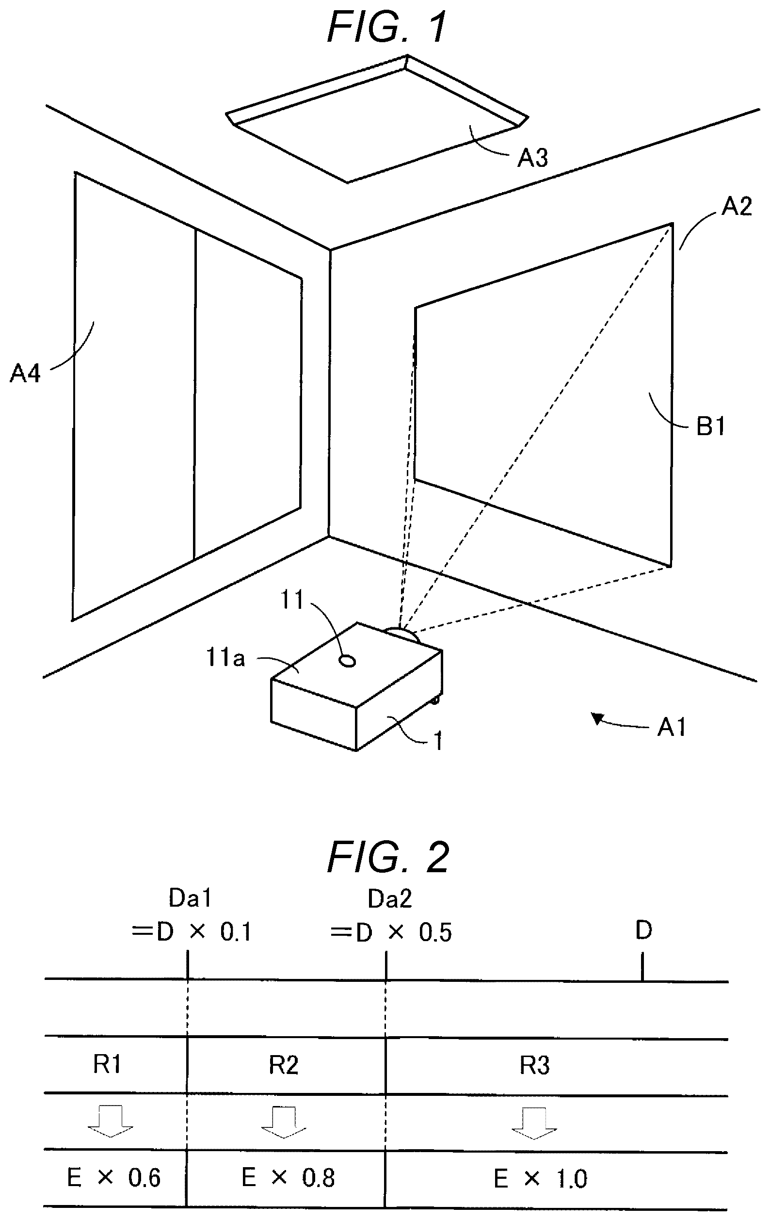
is a schematic view of the projector 1 . The projector 1 is arranged in a room A 1 . The room A 1 is, for example, a conference room, a living room, a bedroom, or a private room. The room A 1 is an example of an environment where the projector 1 is arranged. The room A 1 includes a wall A 2 , an illumination device A 3 , and a window A 4 . The room A 1 may not include the window A 4 .
The projector 1 projects an image B 1 onto the wall A 2 and thus displays the image B 1 on the wall A 2 .
The projector 1 is an example of a display device. The display device is not limited to the projector 1 . The display device may be, for example, a display such as an FPD (flat panel display). The FPD is, for example, a liquid crystal display, a plasma display, or an organic EL (electroluminescence) display.
The wall A 2 is an example of a display surface. The display surface is not limited to the wall A 2 . The display surface may be, for example, a screen, a ceiling, a corridor, or a merchandise. When the display device is a display, a screen where an image is displayed in the display is an example of the display surface.
The projector 1 includes a sensor 11 . The sensor 11 is an illuminance sensor. The sensor 11 is not limited to the illuminance sensor. The sensor 11 may be, for example, a camera. The sensor 11 is located at a top surface 11 a of the projector 1 . The position of the sensor 11 is not limited to the position shown in and can be changed according to need. The sensor 11 detects the illuminance in the room A 1 . The sensor 11 outputs an illuminance signal C 1 . The illuminance signal C 1 is a signal representing the result of the detection of the illuminance in the room A 1 . The illuminance signal C 1 is an example of an output signal from the sensor 11 .
The projector 1 controls the brightness of the image B 1 according to the illuminance in the room A 1 . For example, the projector 1 makes the image B 1 darker as the illuminance in the room A 1 becomes lower. In an example, the projector 1 controls the brightness of the image B 1 in such a way that the illuminance in the room A 1 and the illuminance on the wall A 2 , where the image B 1 is projected, are in the relationship of 1:7.
The projector 1 controls the brightness of the image B 1 , based on the relationship between the illuminance in the room A 1 and a reference value D of illuminance. The reference value D of illuminance is, for example, an upper limit value that is conceivable as the illuminance in the room A 1 . The reference value D of illuminance is not limited to the upper limit value that is conceivable as the illuminance in the room A 1 , and can be changed according to need.
The projector 1 sets two thresholds Da based on the reference value D of illuminance. The two thresholds Da are an example of one or more thresholds. The one or more thresholds are not limited to the two thresholds Da and may be, for example, one threshold, or three or more thresholds.
The two thresholds Da include a first threshold Da 1 and a second threshold Da 2 . The first threshold Da 1 is a value that is 10% of the reference value D of illuminance. The second threshold Da 2 is a value that is 50% of the reference value D of illuminance. The relationship between the first threshold Da 1 and the reference value D of illuminance and the relationship between the second threshold Da 2 and the reference value D of illuminance are not limited to the foregoing relationships and can be changed according to need.
The projector 1 controls the brightness of the image B 1 , based on the high-low relationship between the two thresholds Da and the illuminance in the room A 1 . The projector 1 includes a light source 121 for projecting the image B 1 , as described later. The projector 1 controls the luminance of the light source 121 and thus controls the brightness of the image B 1 .
shows an example of the relationship between the illuminance in the room A 1 and the luminance of the light source 121 in design. The relationship between the illuminance in the room A 1 and the luminance of the light source 121 in design is not limited to the relationship shown in and can be changed according to need. In , the reference value D of illuminance is, for example, 100 lx. When the reference value D of illuminance is 100 lx, the first threshold Da 1 is 10 lx because the first threshold Da 1 is a value that is 10% of the reference value D of illuminance. When the reference value D of illuminance is 100 lx, the second threshold Da 2 is 50 lx because the second threshold Da 2 is a value that is 50% of the reference value D of illuminance. The reference value D of illuminance is not limited to 100 lx and can be changed according to need.
also shows a first range R 1 , a second range R 2 , a third range R 3 , and a maximum luminance E. The first range R 1 is a range of illuminance equal to and lower than the first threshold Da 1 . The second range R 2 is a range of illuminance higher than the first threshold Da 1 and equal to and lower than the second threshold Da 2 . The third range R 3 is a range of illuminance higher than the second threshold Da 2 . The maximum luminance E is the maximum luminance of the light source 121 .
When the illuminance in the room A 1 is included in the first range R 1 , the luminance of the light source 121 is set to be 60% of the maximum luminance E. When the illuminance in the room A 1 is included in the second range R 2 , the luminance of the light source 121 is set to be 80% of the maximum luminance E. When the illuminance in the room A 1 is included in the third range R 3 , the luminance of the light source 121 is set to be 100% of the maximum luminance E.
The projector 1 decides an illuminance F represented by the illuminance signal C 1 outputted from the sensor 11 , as the illuminance in the room A 1 . However, the illuminance F represented by the illuminance signal C 1 changes, for example, according to the positional relationship between the sensor 11 and the illumination device A 3 . Therefore, the illuminance F represented by the illuminance signal C 1 may not represent the actual illuminance in the room A 1 .
shows the relationship between an angle of incidence M of light on the sensor 11 and the illuminance F represented by the illuminance signal C 1 . In , the vertical axis represents the illuminance N and the horizontal axis represents the angle of incidence M. As shown in , the illuminance F represented by the illuminance signal C 1 changes according to the angle of incidence M of light on the sensor 11 . For example, the illuminance F represented by the illuminance signal C 1 becomes higher as the absolute value of the angle of incidence M of light on the sensor 11 becomes smaller. Therefore, when the angle of incidence M of light on the sensor 11 is 0 degrees, the illuminance F represented by the illuminance signal C 1 may be higher than the illuminance in the room A 1 .
The illuminance F represented by the illuminance signal C 1 also changes according to the distance between the sensor 11 and the illumination device A 3 . For example, the illuminance F represented by the illuminance signal C 1 becomes higher as the distance between the sensor 11 and the illumination device A 3 becomes shorter. Therefore, when the sensor 11 is located near the illumination device A 3 , the illuminance F represented by the illuminance signal C 1 may be higher than the illuminance in the room A 1 .
Also, when the sensor 11 receives sunlight via the window A 4 , the illuminance F represented by the illuminance signal C 1 may be higher than the illuminance in the room A 1 .
The illuminance F represented by the illuminance signal C 1 may become higher than the illuminance in the room A 1 , due to the individual specificity of the sensor 11 .
Accordingly, the projector 1 increases the reference value D of illuminance when the illuminance F represented by the illuminance signal C 1 may be higher than the illuminance in the room A 1 . Therefore, even when the illuminance F represented by the illuminance signal C 1 is higher than the actual illuminance in the room A 1 , the relative relationship between the illuminance F represented by the illuminance signal C 1 and the reference value D of illuminance can be maintained. Thus, even when the illuminance F represented by the illuminance signal C 1 is higher than the actual illuminance in the room A 1 , the projector 1 can control the brightness of the image B 1 similarly to when the illuminance F represented by the illuminance signal C 1 is the actual illuminance in the room A 1 .
A 2 : Example of Projector 1
shows an example of the projector 1 . The projector 1 includes an image projection device 12 , an operation device 13 , a storage device 14 , and a processing device 15 , in addition to the sensor 11 .
The image projection device 12 projects the image B 1 . The image projection device 12 includes the light source 121 , a light modulation device 122 , and a projection system 123 .
The light source 121 includes an LED (light-emitting diode). The light source 121 may include, for example, a xenon lamp, an ultra-high-pressure mercury lamp, or a laser light source, instead of the LED. The light source 121 emits light H 1 based on a luminance signal G 1 provided from the processing device 15 . The luminance signal G 1 is a signal designating the luminance of the light source 121 . The light source 121 emits light with the luminance designated by the luminance signal G 1 and thus emits the light H 1 .
The light modulation device 122 includes a liquid crystal light valve. The light modulation device 122 may include a DMD (digital mirror device) instead of the liquid crystal light valve. The light modulation device 122 modulates the light H 1 , based on an image signal G 2 provided from the processing device 15 , and thus generates image light H 2 . The image signal G 2 is a signal representing the image B 1 . The image light H 2 is light representing the image B 1 .
The projection system 123 includes one or a plurality of lenses. The projection system 123 projects the image light H 2 onto the wall A 2 and thus displays the image B 1 on the wall A 2 .
The operation device 13 includes various operation buttons and operation keys or a touch panel. The operation device 13 accepts an input operation from a user. The operation device 13 may be a remote controller transmitting information based on the input operation, wirelessly or via a wire. In this case, the projector 1 includes a receiver receiving the information from the remote controller. The remote controller has various operation buttons, operation keys or a touch panel for accepting the input operation. The operation device 13 outputs an operation signal J 1 . The operation signal J 1 is a signal representing the input operation.
The storage device 14 is a computer-readable recording medium. The storage device 14 includes a non-volatile memory and a volatile memory. The non-volatile memory is, for example, a ROM (read-only memory), an EPROM (erasable programmable read-only memory), and an EEPROM (electrically erasable programmable read-only memory). The volatile memory is, for example, a RAM (random-access memory).
The storage device 14 stores the reference value D of illuminance and a program P 1 . The program P 1 defines operations of the projector 1 . The storage device 14 may store the program P 1 read from a storage device in a server, not illustrated. In this case, the storage device in the server is an example of a computer-readable recording medium.
The processing device 15 includes one or a plurality of CPUs (central processing units). The one or a plurality of CPUs is an example of one or a plurality of processors. Each of the processing device 15 , the processor, and the CPU is an example of a computer. The processing device 15 is an example of a controller.
The processing device 15 reads the program P 1 from the storage device 14 . The processing device 15 executes the program P 1 and thus functions as an acquirer 151 , a changer 152 , and an image controller 153 . At least one of the acquirer 151 , the changer 152 , and the image controller 153 may be formed of a circuit such as a DSP (digital signal processor) and an ASIC (application-specific integrated circuit).
The acquirer 151 acquires the illuminance signal C 1 . For example, when the operation signal J 1 indicating the power-on of the projector 1 is outputted from the operation device 13 , the acquirer 151 acquires the illuminance signal C 1 outputted from the sensor 11 . The acquirer 151 provides the illuminance signal C 1 to the changer 152 and the image controller 153 .
The changer 152 changes the reference value D of illuminance, based on the illuminance F represented by the illuminance signal C 1 . For example, when a first illuminance F 1 represented by the illuminance signal C 1 in the circumstance where the reference value D of illuminance is a first reference illuminance D 1 is higher than the first reference illuminance D 1 , the changer 152 changes the reference value D of illuminance from the first reference illuminance D 1 to a second reference illuminance D 2 that is higher than the first reference illuminance D 1 . The first reference illuminance D 1 is, for example, an upper limit value that is conceivable as the illuminance in the room A 1 . The first reference illuminance D 1 is, for example, 100 lx. The first reference illuminance D 1 is not limited to 100 lx. The first reference illuminance D 1 may be an illuminance lower than 100 lx or an illuminance higher than 100 lx. The first reference illuminance D 1 may be changed according to the direction of the projector 1 . The first reference illuminance D 1 is 100 lx, for example, when the projector 1 is placed on the floor, and 300 lx when the projector 1 is suspended from the ceiling. The first illuminance F 1 is the illuminance F represented by the illuminance signal C 1 outputted from the sensor 11 in the circumstance where the reference value D of illuminance is the first reference illuminance D 1 .
The circumstance where the first illuminance F 1 is higher than the first reference illuminance D 1 occurs, for example, when the sensor 11 receives sunlight and when the sensor 11 is a sensor outputting the illuminance signal C 1 representing an illuminance higher than the actual illuminance of a detection target. In this case, the first illuminance F 1 represented by the illuminance signal C 1 from the sensor 11 is higher than the actual illuminance in the room A 1 . In this case, the changer 152 changes the reference value D of illuminance from the first reference illuminance D 1 to the second reference illuminance D 2 , which is higher than the first reference illuminance D 1 .
An example of the second reference illuminance D 2 is a limit value of the reference value D of illuminance, that is, an upper limit value of the reference value D of illuminance. Hereinafter, the limit value of the reference value D of illuminance is referred to as a third reference illuminance D 3 . The third reference illuminance D 3 is an illuminance higher than the first reference illuminance D 1 . The third reference illuminance D 3 is, for example, 600 lx. The third reference illuminance D 3 is not limited to 600 lx and may be any illuminance higher than the first reference illuminance D 1 . When the first illuminance F 1 is equal to or higher than the third reference illuminance D 3 , the changer 152 changes the reference value D of illuminance from the first reference illuminance D 1 to the third reference illuminance D 3 .
Another example of the second reference illuminance D 2 is the first illuminance F 1 higher than the first reference illuminance D 1 and lower than the third reference illuminance D 3 . When the first illuminance F 1 is higher than the first reference illuminance D 1 and lower than the third reference illuminance D 3 , the changer 152 changes the reference value D of illuminance from the first reference illuminance D 1 to the first illuminance F 1 . In this case, the first illuminance F 1 is an example of an illuminance between the first reference illuminance D 1 and the third reference illuminance D 3 . The illuminance between the first reference illuminance D 1 and the third reference illuminance D 3 is not limited to the first illuminance F 1 and may be an illuminance between the first reference illuminance D 1 and the first illuminance F 1 or an illuminance between the first illuminance F 1 and the third reference illuminance D 3 .
Meanwhile, when the first illuminance F 1 is equal to or lower than the first reference illuminance D 1 , the changer 152 does not change the reference value D of illuminance and maintains the circumstance where the reference value D of illuminance is the first reference illuminance D 1 .
The image controller 153 controls the brightness of the image B 1 , based on the relationship between the reference value D of illuminance and the illuminance F represented by the illuminance signal C 1 . For example, the image controller 153 controls the brightness of the image B 1 , based on the relative relationship between the reference value D of illuminance and the illuminance F represented by the illuminance signal C 1 .
For example, the image controller 153 controls the brightness of the image B 1 , based on the high-low relationship between one or more thresholds Da specified based on the reference value D of illuminance, and the illuminance F represented by the illuminance signal C 1 .
In an example, the image controller 153 first sets two thresholds Da, based on the reference value D of illuminance. The two thresholds Da are an example of the one or more thresholds Da. The two thresholds Da are, for example, the first threshold Da 1 and the second threshold Da 2 shown in . The image controller 153 then controls the brightness of the image B 1 displayed on the wall A 2 , based on the high-low relationship between the illuminance F represented by the illuminance signal C 1 and the two thresholds Da.
For example, in the circumstance where the reference value D of illuminance is the second reference illuminance D 2 , the image controller 153 controls the brightness of the image B 1 displayed on the wall A 2 , based on the high-low relationship between the two thresholds Da based on the second reference illuminance D 2 and a second illuminance F 2 represented by the illuminance signal C 1 . The second illuminance F 2 is the illuminance F represented by the illuminance signal C 1 outputted from the sensor 11 in the circumstance where the reference value D of illuminance is the second reference illuminance D 2 .
Meanwhile, in the circumstance where the reference value D of illuminance is the first reference illuminance D 1 , the image controller 153 controls the brightness of the image B 1 displayed on the wall A 2 , based on the high-low relationship between the two thresholds Da based on the first reference illuminance D 1 and a third illuminance F 3 represented by the illuminance signal C 1 . The third illuminance F 3 is the illuminance F represented by the illuminance signal C 1 outputted from the sensor 11 in the circumstance where the reference value D of illuminance is maintained at the first reference illuminance D 1 .
The image controller 153 controls the luminance of the light source 121 as shown in , based on the high-low relationship between the illuminance F represented by the illuminance signal C 1 and the two thresholds Da, and thus controls the brightness of the image B 1 .
For example, the image controller 153 sets the luminance of the light source 121 designated by the luminance signal G 1 , as shown in , based on the high-low relationship between the illuminance F represented by the illuminance signal C 1 and the two thresholds Da. The image controller 153 provides the luminance signal G 1 set as shown in , to the image projection device 12 , and thus controls the brightness of the image B 1 . The image controller 153 may adjust the image signal G 2 instead of the luminance signal G 1 and thus may control the brightness of the image B 1 . The image controller 153 may adjust both of the luminance signal G 1 and the image signal G 2 and thus may control the brightness of the image B 1 .
A 3 : Outline of Operations
explains an outline of operations of the projector 1 .
In step S 101 , the projector 1 decides the reference value D of illuminance, based on the illuminance F represented by the illuminance signal C 1 .
Then, in step S 102 , the projector 1 controls the brightness of the image B 1 , based on the relative relationship between the illuminance F represented by the illuminance signal C 1 and the reference value D of illuminance.
A 4 : An Example of Operation of Deciding Reference Value D of Illuminance
shows an example of the operation of deciding the reference value D of illuminance in step S 101 in . At the start of the processing shown in , the first reference illuminance D 1 is set as the reference value D of illuminance.
As the acquirer 151 acquires the operation signal J 1 representing the power-on of the projector 1 from the operation device 13 , the acquirer 151 acquires the illuminance signal C 1 in step S 201 . The acquirer 151 provides the illuminance signal C 1 to the changer 152 .
As the changer 152 receives the illuminance signal C 1 , the changer 152 executes step S 202 . In step S 202 , the changer 152 determines whether the first illuminance F 1 represented by the illuminance signal C 1 outputted from the sensor 11 in the circumstance where the reference value D of illuminance is the first reference illuminance D 1 is higher than the first reference illuminance D 1 or not.
When the changer 152 determines in step S 202 that the first illuminance F 1 is equal to or lower than the first reference illuminance D 1 , the changer 152 in step S 203 maintains the reference value D of illuminance at the first reference illuminance D 1 . That is, the changer 152 decides the first reference illuminance D 1 as the reference value D of illuminance.
When the changer 152 determines in step S 202 that the first illuminance F 1 is higher than the first reference illuminance D 1 , the changer 152 in step S 204 determines whether the first illuminance F 1 is equal to or higher than the third reference illuminance D 3 or not.
When the changer 152 determines in step S 204 that the first illuminance F 1 is equal to or higher than the third reference illuminance D 3 , the changer 152 in step S 205 changes the reference value D of illuminance from the first reference illuminance D 1 to the third reference illuminance D 3 . That is, the changer 152 decides the third reference illuminance D 3 as the reference value D of illuminance.
When the changer 152 determines in step S 204 that the first illuminance F 1 is lower than the third reference illuminance D 3 , the changer 152 in step S 206 changes the reference value D of illuminance from the first reference illuminance D 1 to the first illuminance F 1 . That is, the changer 152 decides the first illuminance F 1 as the reference value D of illuminance.
A 5 : An Example of Operation of Controlling Brightness of Image B 1
shows an example of the operation of controlling the brightness of the image B 1 in step S 102 in . The first reference illuminance D 1 is 100 lx. The third reference illuminance D 3 is 600 lx.
In step S 301 , the acquirer 151 acquires the illuminance signal C 1 . The acquirer 151 provides the illuminance signal C 1 to the image controller 153 .
As the image controller 153 receives the illuminance signal C 1 , the image controller 153 executes step S 302 . In step S 302 , the image controller 153 sets the first threshold Da 1 and the second threshold Da 2 , based on the reference value D of illuminance. The first threshold Da 1 is a value that is 10% of the reference value D of illuminance. The second threshold Da 2 is a value that is 50% of the reference value D of illuminance.
shows an example of the first threshold Da 1 and the second threshold Da 2 set when the reference value D of illuminance is maintained at the first reference illuminance D 1 . The circumstance where the reference value D of illuminance is maintained at the first reference illuminance D 1 occurs, for example, when the illuminance signal C 1 from the sensor 11 represents 100 lx in the circumstance where the actual illuminance in the room A 1 is 100 lx. In , the reference value D of illuminance is maintained at the first reference illuminance D 1 and therefore the reference value D of illuminance is 100 lx. The first threshold Da 1 is a value that is 10% of the reference value D of illuminance and therefore is 10 lx. The second threshold Da 2 is a value that is 50% of the reference value D of illuminance and therefore is 50 lx.
shows an example of the first threshold Da 1 and the second threshold Da 2 set when the reference value D of illuminance is the first illuminance F 1 . The circumstance where the reference value D of illuminance is the first illuminance F 1 occurs, for example, when, in the state where the actual illuminance in the room A 1 is 100 lx, the illuminance signal C 1 from the sensor 11 represents 500 lx, which is an illuminance five times the actual illuminance in the room A 1 . In , the first illuminance F 1 is 500 lx, which is five times the first reference illuminance D 1 . In , the reference value D of illuminance is the first illuminance F 1 and therefore the reference value D of illuminance is 500 lx. The first threshold Da 1 is a value that is 10% of the reference value D of illuminance and therefore is 50 lx. The second threshold Da 2 is a value that is 50% of the reference value D of illuminance and therefore is 250 lx.
The first threshold Da 1 in is five times the first threshold Da 1 in . The second threshold Da 2 in is five times the second threshold Da 2 in . Therefore, when the illuminance signal C 1 represents an illuminance five times the actual illuminance in the room A 1 , the first threshold Da 1 and the second threshold Da 2 represent illuminances five times the first threshold Da 1 and the second threshold Da 2 set when the illuminance signal C 1 represents the actual illuminance in the room A 1 . Thus, the relative relationship between the illuminance F represented by the illuminance signal C 1 , and the first threshold Da 1 and the second threshold Da 2 , is maintained.
shows an example of the first threshold Da 1 and the second threshold Da 2 set when the reference value D of illuminance is the third reference illuminance D 3 . The circumstance where the reference value D of illuminance is the third reference illuminance D 3 occurs, for example, when the sensor 11 outputs the illuminance signal C 1 representing 1000 lx due to the entry of sunlight into the sensor 11 when the actual illuminance in the room A 1 is 100 lx. In , the reference value D of illuminance is the third reference illuminance D 3 and therefore the reference value D of illuminance is 600 lx. The first threshold Da 1 is a value that is 10% of the reference value D of illuminance and therefore is 60 lx. The second threshold Da 2 is a value that is 50% of the reference value D of illuminance and therefore is 300 lx. Since the reference value D of illuminance is set to be the third reference illuminance D 3 , the first threshold Da 1 and the second threshold Da 2 can be restrained from becoming excessively high.
The circumstance where the reference value D of illuminance is the first illuminance F 1 and the circumstance where the reference value D of illuminance is the third reference illuminance D 3 are an example of the circumstance where the reference value D of illuminance is the second reference illuminance D 2 . Hereinafter, to simplify the description, the circumstance where the reference value D of illuminance is the first illuminance F 1 and the circumstance where the reference value D of illuminance is the third reference illuminance D 3 are referred to as the circumstance where the reference value D of illuminance is the second reference illuminance D 2 . When the reference value D of illuminance is the third reference illuminance D 3 , the second reference illuminance D 2 means the third reference illuminance D 3 . When the reference value D of illuminance is the first illuminance F 1 , the second reference illuminance D 2 means the first illuminance F 1 .
In step S 303 in , the image controller 153 determines whether the illuminance F represented by the illuminance signal C 1 is equal to or lower than the first threshold Da 1 or not. That is, the image controller 153 determines whether the illuminance F represented by the illuminance signal C 1 is included in the first range R 1 shown in or not.
For example, when the reference value D of illuminance is the second reference illuminance D 2 , the image controller 153 determines whether the second illuminance F 2 is equal to or lower than the first threshold Da 1 or not. The second illuminance F 2 is the illuminance F represented by the illuminance signal C 1 outputted from the sensor 11 in the circumstance where the reference value D of illuminance is the second reference illuminance D 2 .
Meanwhile, when the reference value D of illuminance is the first reference illuminance D 1 , the image controller 153 determines whether the third illuminance F 3 is equal to or lower than the first threshold Da 1 or not. The third illuminance F 3 is the illuminance F represented by the illuminance signal C 1 outputted from the sensor 11 in the circumstance where the reference value D of illuminance is maintained at the first reference illuminance D 1 .
When the image controller 153 determines in step S 303 that the illuminance F represented by the illuminance signal C 1 is equal to or lower than the first threshold Da 1 , the image controller 153 in step S 304 generates the luminance signal G 1 designating a luminance that is 60% of the maximum luminance E of the light source 121 . Subsequently, the image controller 153 provides the luminance signal G 1 designating the luminance that is 60% of the maximum luminance E of the light source 121 , and the image signal G 2 , to the image projection device 12 . In the image projection device 12 , the light source 121 emits the light H 1 with the luminance that is 60% of the maximum luminance E, based on the luminance signal G 1 . The light modulation device 122 modulates the light H 1 emitted from the light source 121 , based on the image signal G 2 , and thus generates the image light H 2 . The projection system 123 projects the image light H 2 onto the wall A 2 and thus displays the image B 1 on the wall A 2 .
When the image controller 153 determines in step S 303 that the illuminance F represented by the illuminance signal C 1 is higher than the first threshold Da 1 , the image controller 153 in step S 305 determines whether the illuminance F represented by the illuminance signal C 1 is higher than the second threshold Da 2 or not. That is, the image controller 153 determines whether the illuminance F represented by the illuminance signal C 1 is included in the third range R 3 shown in or not.
For example, when the reference value D of illuminance is the second reference illuminance D 2 , the image controller 153 determines whether the second illuminance F 2 is higher than the second threshold Da 2 or not. The second illuminance F 2 is the illuminance F represented by the illuminance signal C 1 outputted from the sensor 11 in the circumstance where the reference value D of illuminance is the second reference illuminance D 2 .
Meanwhile, when the reference value D of illuminance is the first reference illuminance D 1 , the image controller 153 determines whether the third illuminance F 3 is higher than the second threshold Da 2 or not. The third illuminance F 3 is the illuminance F represented by the illuminance signal C 1 outputted from the sensor 11 in the circumstance where the reference value D of illuminance is maintained at the first reference illuminance D 1 .
When the image controller 153 determines in step S 305 that the illuminance F represented by the illuminance signal C 1 is higher than the second threshold Da 2 , the image controller 153 in step S 306 generates the luminance signal G 1 designating a luminance that is 100% of the maximum luminance E of the light source 121 . Subsequently, the image controller 153 provides the luminance signal G 1 designating the luminance that is 100% of the maximum luminance E of the light source 121 , and the image signal G 2 , to the image projection device 12 . In the image projection device 12 , the light source 121 emits the light H 1 with the luminance that is 100% of the maximum luminance E, based on the luminance signal G 1 . The light modulation device 122 modulates the light H 1 emitted from the light source 121 , based on the image signal G 2 , and thus generates the image light H 2 . The projection system 123 projects the image light H 2 onto the wall A 2 and thus displays the image B 1 on the wall A 2 .
When the image controller 153 determines in step S 305 that the illuminance F represented by the illuminance signal C 1 is equal to or lower than the second threshold Da 2 , the image controller 153 determines that the illuminance F represented by the illuminance signal C 1 is included in the second range R 2 shown in . Then, the image controller 153 generates the luminance signal G 1 designating a luminance that is 80% of the maximum luminance E of the light source 121 . Subsequently, the image controller 153 provides the luminance signal G 1 designating the luminance that is 80% of the maximum luminance E of the light source 121 , and the image signal G 2 , to the image projection device 12 . In the image projection device 12 , the light source 121 emits the light H 1 with the luminance that is 80% of the maximum luminance E, based on the luminance signal G 1 . The light modulation device 122 modulates the light H 1 emitted from the light source 121 , based on the image signal G 2 , and thus generates the image light H 2 . The projection system 123 projects the image light H 2 onto the wall A 2 and thus displays the image B 1 on the wall A 2 .
A 6 : Summary of First Embodiment
The control method for the projector 1 and the projector 1 according to the first embodiment include the aspects described below.
The control method for the projector 1 is executed by the processing device 15 of the projector 1 . The processing device 15 functions as the acquirer 151 , the changer 152 , and the image controller 153 . The acquirer 151 acquires the illuminance signal C 1 outputted from the sensor 11 detecting the illuminance in the room A 1 , where the projector 1 is arranged. When the first illuminance F 1 represented by the illuminance signal C 1 from the sensor 11 in the circumstance where the reference value D of illuminance is the first reference illuminance D 1 is higher than the first reference illuminance D 1 , the changer 152 changes the reference value D of illuminance from the first reference illuminance D 1 to the second reference illuminance D 2 , which is higher than the first reference illuminance D 1 . The image controller 153 controls the brightness of the image B 1 displayed on the wall A 2 , based on the relationship between the second illuminance F 2 represented by the illuminance signal C 1 from the sensor 11 in the circumstance where the reference value D of illuminance is the second reference illuminance D 2 , and the second reference illuminance D 2 .
According to this aspect, when the illuminance F represented by the illuminance signal C 1 from the sensor 11 is higher than the actual illuminance in the room A 1 , the changer 152 increases the reference value D of illuminance. Therefore, even when the illuminance F is higher than the actual illuminance in the room A 1 , the relationship between the illuminance F and the reference value D of illuminance can be maintained. Thus, for example, even when the illuminance F is higher than the actual illuminance in the room A 1 , the brightness of the image B 1 can be controlled similarly to when the illuminance F represents the actual illuminance in the room A 1 . Therefore, the image with the brightness corresponding to the actual illuminance in the environment where the projector 1 is installed can be displayed. Accordingly, the situation where the image becomes less visually recognizable due to the inability to display the image with the brightness corresponding to the actual illuminance in the environment where the projector 1 is installed, can be reduced.
A comparative example will now be described. In the comparative example, the reference value D of illuminance is fixed. That is, the reference value D of illuminance is not changed. Specifically, the reference value D of illuminance is fixed at 100 lx. Therefore, the first threshold Da 1 is fixed at 10 lx. The second threshold Da 2 is fixed at 50 lx.
In the comparative example, for example, when the sensor 11 outputs the illuminance signal C 1 representing an illuminance five times the actual illuminance in the room A 1 , the following circumstance occurs.
When the actual illuminance in the room A 1 is 2 lx, the illuminance signal C 1 from the sensor 11 represents 10 lx. Therefore, for example, when the actual illuminance in the room A 1 changes from an illuminance lower than 2 lx to an illuminance higher than 2 lx, the brightness of the image B 1 increases. Accordingly, in practice, the first threshold Da 1 is 2 lx instead of 10 lx. Meanwhile, when the actual illuminance in the room A 1 is 10 lx, the illuminance signal C 1 from the sensor 11 represents 50 lx. Therefore, for example, when the actual illuminance in the room A 1 changes from an illuminance lower than 10 lx to an illuminance higher than 10 lx, the brightness of the image B 1 increases. Accordingly, in practice, the second threshold Da 2 is 10 lx instead of 50 lx.
In this way, when the sensor 11 outputs the illuminance signal C 1 representing an illuminance higher than the actual illuminance in the room A 1 , the first threshold Da 1 and the second threshold Da 2 in practice are lower than the original values. For example, when the sensor 11 outputs the illuminance signal C 1 representing an illuminance five times the actual illuminance in the room A 1 , the first threshold Da 1 and the second threshold Da 2 in practice are values one-fifth the original values. Therefore, when the illuminance in the room A 1 does not become equal to or lower than 10 lx despite the execution of the processing of controlling the brightness of the image B 1 shown in , a first problem arises in that the brightness of the image B 1 is not adjusted.
Also the space between the first threshold Da 1 and the second threshold Da 2 is in practice narrower than the original space. For example, when the sensor 11 outputs the illuminance signal C 1 representing an illuminance five times the actual illuminance in the room A 1 , the space between the first threshold Da 1 and the second threshold Da 2 is in practice one-fifth the original space.
The light reflected by the wall A 2 reaches the sensor 11 , too. Therefore, the illuminance F represented by the illuminance signal C 1 from the sensor 11 changes according to the change in the brightness of the image B 1 projected on the wall A 2 . When the space between the first threshold Da 1 and the second threshold Da 2 is too narrow, the illuminance F represented by the illuminance signal C 1 may change within a range around the first threshold Da 1 or the second threshold Da 2 according to the change in the brightness of the image B 1 . In this case, a second problem arises in that the brightness of the image B 1 is not stable.
In this respect, in this embodiment, when the illuminance F represented by the illuminance signal C 1 from the sensor 11 is higher than the actual illuminance in the room A 1 , the changer 152 increases the reference value D of illuminance. Therefore, the occurrence of the first and second problems arising in the configuration where the reference value D of illuminance is fixed can be restrained.
Also, according to this embodiment, when the first illuminance F 1 is equal to or higher than the third reference illuminance D 3 , which is higher than the first reference illuminance D 1 , the second reference illuminance D 2 is the third reference illuminance D 3 . When the first illuminance F 1 is higher than the first reference illuminance D 1 and lower than the third reference illuminance D 3 , the second reference illuminance D 2 is an illuminance between the first reference illuminance D 1 and the third reference illuminance D 3 .
According to this aspect, the third reference illuminance D 3 can be defined as the upper limit of the reference value D of illuminance. Therefore, the reference value D of illuminance can be restrained from becoming excessively high, compared with the configuration where the second reference illuminance D 2 is the first illuminance F 1 when the first illuminance F 1 is equal to or higher than the third reference illuminance D 3 .
Also, according to this embodiment, the image controller 153 sets the two thresholds Da, that is, the first threshold Da 1 and the second threshold Da 2 , based on the second reference illuminance D 2 . The image controller 153 controls the brightness of the image B 1 , based on the high-low relationship between the two thresholds Da and the second illuminance F 2 .
According to this aspect, a plurality of thresholds are changed according to the change in one reference value D of illuminance. Therefore, a plurality of thresholds can be more easily changed than in the configuration where the plurality of thresholds are individually changed.
In this embodiment, the two thresholds Da are an example of the one or more thresholds Da. The high-low relationship between the one or more thresholds Da and the second illuminance F 2 is an example of the relationship between the second illuminance F 2 and the second reference illuminance D 2 . The relationship between the second illuminance F 2 and the second reference illuminance D 2 is not limited to the high-low relationship between the one or more thresholds Da and the second illuminance F 2 . For example, the relationship between the second illuminance F 2 and the second reference illuminance D 2 may be the ratio of the second illuminance F 2 to the second reference illuminance D 2 . In this case, the image controller 153 makes the image B 1 brighter as the ratio of the second illuminance F 2 to the second reference illuminance D 2 becomes higher.
Also, according to this embodiment, the acquirer 151 and the changer 152 automatically start the operation of deciding the reference value D of illuminance in response to the power-on of the projector 1 .
According to this aspect, the burden of the operation on the user can be reduced, compared with the configuration where the operation of deciding the reference value D of illuminance is manually started.
B: Modification Examples
Modification aspects of the foregoing embodiment will now be described. Two or more aspects arbitrarily selected from the aspects described below may be combined together where appropriate within a range that does not make these aspects contradictory to each other.
B 1 : First Modification Example
In the first embodiment, the third reference illuminance D 3 , which is the upper limit of the reference value D of illuminance, may be omitted. In this case, for example, the first illuminance F 1 is used as the second reference illuminance D 2 . That is, the second reference illuminance D 2 may be defined to be the first illuminance F 1 . For example, when the first illuminance F 1 is higher than the first reference illuminance D 1 , the changer 152 changes the reference value D from the first reference illuminance D 1 to the first illuminance F 1 .
The first modification example can eliminate the need for the third reference illuminance D 3 and therefore can eliminate the need for the processing of comparing the third reference illuminance D 3 and the first illuminance F 1 .
B 2 : Second Modification Example
In the first embodiment and the first modification example, the operation device 13 may accept a first start instruction designating the start of the operation of deciding the reference value D of illuminance. The acquirer 151 and the changer 152 may start the operation of deciding the reference value D of illuminance in response to the operation device 13 accepting the first start instruction. In this case, the image controller 153 may execute the operation of controlling the brightness of the image B 1 , following the operation of deciding the reference value D of illuminance in response to the acceptance of the first start instruction.
According to the second modification example, the user can input the first start instruction to the operation device 13 and thus can execute the operation of deciding the reference value D of illuminance at a timing preferred by the user.
B 3 : Third Modification Example
In the first embodiment and the first and second modification examples, the operation device 13 may accept a second start instruction designating the start of the operation of controlling the brightness of the image B 1 . The acquirer 151 and the changer 152 may start the operation of deciding the reference value D of illuminance in response to the operation device 13 accepting the second start instruction. In this case, the image controller 153 may execute the operation of controlling the brightness of the image B 1 , following the operation of deciding the reference value D of illuminance in response to the acceptance of the second start instruction.
According to the third modification example, the user can input the second start instruction to the operation device 13 and thus can execute the operation of deciding the reference value D of illuminance at a timing preferred by the user.
B 4 : Fourth Modification Example
In the first embodiment and the first to third modification examples, the illuminance F represented by the illuminance signal C 1 from the sensor 11 is used as an example of the illuminance specified based on the illuminance signal C 1 from the sensor 11 . For example, the first illuminance F 1 , the second illuminance F 2 , and the third illuminance F 3 are an example of the illuminance specified based on the illuminance signal C 1 from the sensor 11 .
However, the illuminance specified based on the illuminance signal C 1 from the sensor 11 is not limited to the illuminance F represented by the illuminance signal C 1 from the sensor 11 . For example, the illuminance specified based on the illuminance signal C 1 from the sensor 11 may be an illuminance specified based on a plurality of illuminances acquired from the illuminance signal C 1 representing an illuminance in time series.
For example, the acquirer 151 acquires an illuminance three times at an interval of one second from the illuminance signal C 1 representing an illuminance in time series. The time interval at which the illuminance is acquired is not limited to the interval of one second and can be changed according to need. The number of illuminances acquired from the illuminance signal C 1 is not limited to three and may be two or an integer equal to or greater than four. The acquirer 151 provides the three illuminances acquired in the three times of acquisition, to the changer 152 and the image controller 153 .
The changer 152 specifies the first illuminance F 1 , based on the three illuminances. For example, the changer 152 specifies the average value of the three illuminances as the first illuminance F 1 . In the configuration where the average value of the three illuminances is specified as the first illuminance F 1 , for example, even when one illuminance of the three illuminances includes a noise, the influence of the noise can be reduced, compared with the configuration where the one illuminance including the noise is used as the first illuminance F 1 .
The changer 152 may specify the lowest illuminance of the three illuminances as the first illuminance F 1 . In the configuration where the lowest illuminance of the three illuminances is specified as the first illuminance F 1 , for example, even when one illuminance of the three illuminances is an excessively high illuminance due to sunlight, the influence of the excessively high illuminance on the first illuminance F 1 can be eliminated.
The changer 152 may specify the highest illuminance of the three illuminances as the first illuminance F 1 . In the configuration where the highest illuminance of the three illuminances is specified as the first illuminance F 1 , for example, even when one illuminance of the three illuminances is an excessively low illuminance because the sensor 11 is covered with an object such as a hand, the influence of the excessively low illuminance on the first illuminance F 1 can be eliminated.
The image controller 153 may specify the second illuminance F 2 or the third illuminance F 3 , based on the three illuminances. The technique in which the image controller 153 specifies the second illuminance F 2 or the third illuminance F 3 , based on the three illuminances, is similar to, for example, the technique in which the changer 152 specifies the first illuminance F 1 , based on the three illuminances. The changer 152 may specify the average value of the three illuminances as the first illuminance F 1 and the image controller 153 may specify the lowest illuminance or the highest illuminance of the three illuminances as the second illuminance F 2 or the third illuminance F 3 . Also, the changer 152 may specify the lowest illuminance of the three illuminances as the first illuminance F 1 and the image controller 153 may specify the highest illuminance of the three illuminances or the average illuminance of the three illuminances as the second illuminance F 2 or the third illuminance F 3 . Also, the changer 152 may specify the highest illuminance of the three illuminances as the first illuminance F 1 and the image controller 153 may specify the lowest illuminance of the three illuminances or the average illuminance of the three illuminances as the second illuminance F 2 or the third illuminance F 3 .
The fourth modification example can improve the reliability of the illuminance specified based on the illuminance signal C 1 from the sensor 11 .
B 5 : Fifth Modification Example
As described above, the illuminance F represented by the illuminance signal C 1 from the sensor 11 changes, for example, according to the change in the positional relationship between the sensor 11 located in the projector 1 and the illumination device A 3 . Thus, when the projector 1 is used in another room after the use in the room A 1 , the positional relationship between the projector 1 and the illumination device A 3 changes and therefore it is desirable to reset the reference value D of illuminance. Also, when the positional relationship between the projector 1 and the illumination device A 3 changes in the state where the projector 1 is located in the room A 1 , it is desirable to reset the reference value D of illuminance. The reset of the reference value D of illuminance is the processing of returning the reference value D of illuminance from the second reference illuminance D 2 to the first reference illuminance D 1 .
In the first embodiment and the first to fourth modification examples, the reset of the reference value D of illuminance may be executed in response to an operation from the user. For example, the changer 152 may change the reference value D of illuminance from the second reference illuminance D 2 to the first reference illuminance D 1 in response to the operation device 13 accepting an operation representing the reset of the reference value D of illuminance.
Also, the changer 152 may automatically reset the reference value D of illuminance. For example, when the projector 1 is moved from the room A 1 to another room, it is likely that the power of the projector 1 is turned off in the room A 1 and subsequently turned on in the room of destination. Therefore, the changer 152 may change the reference value D of illuminance from the second reference illuminance D 2 to the first reference illuminance D 1 in response to the power-on or power-off of the projector 1 in the circumstance where the reference value D of illuminance is the second reference illuminance D 2 .
In an example, the changer 152 changes the reference value D of illuminance from the second reference illuminance D 2 to the first reference illuminance D 1 in response to the operation device 13 accepting an operation for the power-on of the projector 1 in the circumstance where the reference value D of illuminance is the second reference illuminance D 2 . Also, the changer 152 changes the reference value D of illuminance from the second reference illuminance D 2 to the first reference illuminance D 1 in response to the operation device 13 accepting an operation for the power-off of the projector 1 in the circumstance where the reference value D of illuminance is the second reference illuminance D 2 .
The changer 152 may execute the operation of automatically resetting the reference value D of illuminance in response to the start of the image display by the projector 1 or the stop of the image display by the projector 1 . For example, in the case where the projector 1 is set in a mute state or a pause state in order for the projector 1 to stop displaying the image B 1 in the room A 1 and the mute state or the pause state of the projector 1 is cancelled after the lapse of a predetermined time in order for the projector 1 to start displaying the image B 1 , it is likely that the illuminance in the room A 1 changes with the lapse of time due to sunlight. Therefore, the changer 152 may change the reference value D of illuminance from the second reference illuminance D 2 to the first reference illuminance D 1 in response to the setting or cancellation of the mute state or the pause state of the projector 1 in the circumstance where the reference value D of illuminance is the second reference illuminance D 2 .
According to this aspect, the reference value D of illuminance is changed from the second reference illuminance D 2 to the first reference illuminance D 1 in response to the power-on or power-off of the projector 1 , or the start of the image display or the stop of the image display. Therefore, the reference value D of illuminance is easily changed from the second reference illuminance D 2 to the first reference illuminance D 1 , for example, when the projector 1 is moved to another room or when the illuminance in the room A 1 changes with the lapse of time. Thus, the need for the user to manually reset the reference value D of illuminance is reduced.
B 6 : Sixth Modification Example
In the first embodiment and the first to fifth modification examples, the changer 152 may change the reference value D of illuminance from the second reference illuminance D 2 to the first reference illuminance D 1 after the end of the operation of controlling the brightness of the image B 1 shown in in the circumstance where the reference value D of illuminance is the second reference illuminance D 2 . The operation of controlling the brightness of the image B 1 is an example of the processing of controlling the brightness of the image B 1 , based on the relationship between the second illuminance F 2 and the second reference illuminance D 2 .
For example, the changer 152 changes the reference value D of illuminance from the second reference illuminance D 2 to the first reference illuminance D 1 in response to the operation device 13 accepting an operation-off operation of switching off the operation of controlling the brightness of the image B 1 in the circumstance where the reference value D of illuminance is the second reference illuminance D 2 . Alternatively, the changer 152 changes the reference value D of illuminance from the second reference illuminance D 2 to the first reference illuminance D 1 in response to the operation device 13 accepting an operation-on operation after accepting the operation-off operation in the circumstance where the reference value D of illuminance is the second reference illuminance D 2 .
According to the sixth modification example, the reference value D of illuminance is reset when the operation of controlling the brightness of the image B 1 is newly executed. Therefore, the influence of the past setting of the reference value D of illuminance on the newly executed brightness control operation can be reduced.
B 7 : Seventh Modification Example
In the first embodiment and the first to sixth modification examples, the positional relationship between the sensor 11 and the illumination device A 3 changes with a change in the direction of the projector 1 . The positional relationship between the sensor 11 and the illumination device A 3 also changes with a movement of the projector 1 . As the positional relationship between the sensor 11 and the illumination device A 3 changes, the illuminance F represented by the illuminance signal C 1 from the sensor 11 changes. Therefore, the changer 152 may reset the reference value D of illuminance in response to the change in the direction of the projector 1 . The changer 152 may also reset the reference value D of illuminance in response to the movement of the projector 1 .
shows a projector 1 A according to the seventh modification example. Hereinafter, the projector 1 A will be described mainly in terms of the difference from the projector 1 shown in .
The projector 1 A includes a gyro sensor 16 and an acceleration sensor 17 in addition to the elements included in the projector 1 shown in .
The gyro sensor 16 is a sensor measuring the angular acceleration of the rotation of the projector 1 A. The rotation of the projector 1 A means the change in the direction of the projector 1 A. The gyro sensor 16 generates a rotation signal K 1 , based on the result of the measurement of the angular acceleration of the projector 1 A. The rotation signal K 1 is a signal representing the rotation of the projector 1 A. The change in the direction of the projector 1 A is detected, based on the rotation signal K 1 .
The acceleration sensor 17 is a sensor measuring the acceleration of the projector 1 A. The acceleration sensor 17 generates an acceleration signal L 1 , based on the result of the measurement of the acceleration of the projector 1 A. The acceleration signal L 1 is a signal representing the acceleration of the projector 1 A. The movement of the projector 1 A is detected, based on the acceleration signal L 1 .
The storage device 14 stores a program P 2 instead of the program P 1 . The processing device 15 reads the program P 2 from the storage device 14 . The processing device 15 executes the program P 2 and thus functions as the acquirer 151 , the changer 152 , the image controller 153 , a direction change detector 154 , and a movement detector 155 . At least one of the acquirer 151 , the changer 152 , the image controller 153 , the direction change detector 154 , and the movement detector 155 may be formed of a circuit such as a DSP and an ASIC.
The direction change detector 154 detects the change in the direction of the projector 1 A, based on the rotation signal K 1 . For example, when the rotation signal K 1 represents the rotation of the projector 1 A, the direction change detector 154 detects that the direction of the projector 1 A is changed.
In the circumstance where the projector 1 A has a geometric correction function for correcting a keystone distortion of the image B 1 , geometric correction tends to be used when the direction of the projector 1 A is changed. Therefore, the direction change detector 154 may detect that the direction of the projector 1 A is changed when the projector 1 A performs geometric correction.
In the case where the projector 1 A has selectable installation modes of “suspension from the ceiling” and “placement on the floor”, “suspension from the ceiling” is selected as the installation mode when the projector 1 A is suspended from the ceiling, and “placement on the floor” is selected as the installation mode when the projector 1 A is placed on the floor. Therefore, the direction change detector 154 may detect that the direction of the projector 1 A is changed, in response to the change in the installation mode. The up-down direction of the image B 1 is reversed in response to the change in the installation mode.
The movement detector 155 detects the movement of the projector 1 A, based on the acceleration signal L 1 . For example, when the acceleration signal L 1 represents the acceleration of the projector 1 A, the movement detector 155 detects that the projector 1 A is moved.
The changer 152 changes the reference value D of illuminance from the second reference illuminance D 2 to the first reference illuminance D 1 in response to the detection of the change in the direction of the projector 1 A by the direction change detector 154 in the circumstance where the reference value D of illuminance is the second reference illuminance D 2 .
In this case, the reference value D of illuminance can be changed from the second reference illuminance D 2 to the first reference illuminance D 1 in response to the change in the direction of the projector 1 A.
Also, the changer 152 automatically changes the reference value D of illuminance from the second reference illuminance D 2 to the first reference illuminance D 1 in response to the detection of the movement of the projector 1 A by the movement detector 155 in the circumstance where the reference value D of illuminance is the second reference illuminance D 2 .
In this case, the reference value D of illuminance can be automatically changed from the second reference illuminance D 2 to the first reference illuminance D 1 in response to the movement of the projector 1 A.
The changer 152 may also change the reference value D of illuminance from the second reference illuminance D 2 to the first reference illuminance D 1 corresponding to the direction of the projector 1 A in response to the detection of the change in the direction of the projector 1 A by the direction change detector 154 in the circumstance where the reference value D of illuminance is the second reference illuminance D 2 .
In this case, the reference value D of illuminance can be changed to the first reference illuminance D 1 that is optimum for the direction of the projector 1 A.
Figures (6)
Citations
This patent cites (12)
- US20060119564
- US20090079721
- US20100188325
- US20120242716
- US20170011678
- US20180090045
- US20200227005
- US20200372864
- US20210264876
- US2005-031572
- US2012-198464
- US2014-186071