Repeater Device and Operation of Repeater Device for Non-line-of-sight Communication
Abstract
A repeater device includes a first antenna array on a first surface, a second antenna array on a second surface opposite to the first surface, and control circuitry. The first antenna array includes a plurality of first antenna elements and the second antenna array includes a plurality of second antenna elements, where each first antenna element is coupled to at least one second antenna element. The control circuitry selects at least one first antenna element and a corresponding second antenna element based on a first direction of signal reception with respect to the first antenna array. The selected first antenna element receives a beam of radio frequency (RF) signal in a first radiation pattern from a first network node in the first direction and corresponding second antenna element transmits the received beam of RF signal in a second radiation pattern to a second network node in a second direction.
Claims (17)
1. A first repeater device, comprising: a first antenna array on a first surface, wherein the first antenna array comprises a plurality of first antenna elements, and the plurality of first antenna elements is configured to receive two or more beams of radio frequency (RF) signals in a first radiation pattern from different directions; a second antenna array on a second surface opposite to the first surface, wherein the second antenna array comprises a plurality of second antenna elements, and each first antenna element of the plurality of first antenna elements on the first surface is coupled to at least one second antenna element of the plurality of second antenna elements on the second surface; and control circuitry configured to: select at least one first antenna element of the plurality of first antenna elements and a corresponding at least one second antenna element of the plurality of second antenna elements based on a first direction of signal reception among the different directions with respect to the first antenna array; control the selected at least one first antenna element on the first surface to selectively receive a beam of RF signal of the two or more beams of RF signals in the first radiation pattern from a first network node in the first direction; and transmit the beam of RF signal in a second radiation pattern to a second network node in a second direction from the at least one second antenna element coupled to the selected at least one first antenna element, wherein the second radiation pattern is broader than the first radiation pattern, the first network node and the second network node are in a non-line-of-sight, the first repeater device is a passive repeater device, and the first repeater device is configured to establish a wireless communication between the first network node and the second network node based on: the selective reception of the beam of RF signal of the two or more beams of RF signals, in the first radiation pattern and in the first direction, from the first network node, and re-transmission of the received beam of RF signal, in the second radiation pattern and in the second direction, to the second network node.
10. A first repeater device, comprising: a first antenna array on a first surface, wherein the first antenna array comprises a plurality of first antenna elements, and the plurality of first antenna elements is configured to potentially transmit two or more first beams of radio frequency (RF) signals in a first radiation pattern towards different directions; and a second antenna array on a second surface opposite to the first surface, wherein the second antenna array comprises a plurality of second antenna elements, and each first antenna element of the plurality of first antenna elements on the first surface is coupled to at least one second antenna element of the plurality of second antenna elements on the second surface; and control circuitry configured to: select at least one first antenna element of the plurality of first antenna elements and a corresponding at least one second antenna element of the plurality of second antenna elements based on a first direction of signal transmission among the different directions with respect to the first antenna array; control the at least one second antenna element that is on the second surface and coupled to the selected at least one first antenna element, to selectively receive a second beam of RF signal in a second radiation pattern from a first network node in a second direction; and transmit the second beam of RF signal in the first radiation pattern to a second network node in the first direction from the selected at least one first antenna element on the first surface, wherein the first radiation pattern is narrower than the second radiation pattern, the first network node and the second network node are in a non-line-of-sight, the first repeater device is a passive repeater device, and the first repeater device is configured to establish a wireless communication between the first network node and the second network node based on: the selective reception of the second beam of RF signal, in the second radiation pattern and in the second direction, from the first network node, and selective re-transmission of the received second beam of RE signal, in the first radiation pattern and in the first direction, to the second network node.
16. A method of operation by a repeater device, the method comprising: selecting, by control circuitry of the repeater device, at least one first antenna element of a plurality of first antenna elements in a first antenna array and a corresponding at least one second antenna element of a plurality of second antenna elements in a second antenna array, wherein the first antenna array is on a first surface of the repeater device, the second antenna array is on a second surface of the repeater device, the selection of the at least one first antenna element on the first surface and the corresponding at least one second antenna element on the second surface is based on a first direction of signal reception with respect to the first antenna array, and the second surface is opposite to the first surface; controlling, by the control circuitry, the selected at least one first antenna element on the first surface to selectively receive a beam of radio frequency (RF) signal in a first radiation pattern from a first network node in the first direction; transmitting, by the control circuitry, the beam of RF signal in a second radiation pattern to a second network node in a second direction from the corresponding at least one second antenna element coupled to the selected at least one first antenna element, wherein the second radiation pattern is broader than the first radiation pattern, the first network node and the second network node are in a non-line-of-sight, and the repeater device is a passive repeater device; and establishing, by the repeater device, a wireless communication between the first network node and the second network node based on: the selective reception of the beam of RF signal among two or more beams of RF signals, in the first radiation pattern and in the first direction, from the first network node, wherein the two or more beams of RF signals arrive at the repeater device from different directions, wherein the different directions include the first direction, and re-transmission of the received beam of RF signal, in the second radiation pattern and in the second direction, to the second network node.
Show 14 dependent claims
2. The first repeater device of claim 1 , further comprising: a plurality of switches configured to couple each first antenna element of the plurality of first antenna elements on the first surface to the at least one second antenna element of the plurality of second antenna elements on the second surface; and one or more power sources to power the plurality of switches.
3. The first repeater device of claim 2 , the control circuitry is further configured to: activate a first set of switches of the plurality of switches based on the selected at least one first antenna element; and deactivate a second set of switches of the plurality of switches based on the selected at least one first antenna element, the first set of switches couples the selected at least one first antenna element on the first surface to the corresponding at least one second antenna element on the second surface, and the second set of switches couples remaining first antenna elements of the plurality of first antenna elements on the first surface to corresponding second antenna elements of the plurality of second antenna elements on the second surface.
4. The first repeater device of claim 3 , wherein based on the deactivation of the second set of switches, the remaining first antenna elements of the plurality of first antenna elements and the corresponding second antenna elements of the plurality of second antenna elements are deactivated.
5. The first repeater device of claim 1 , further comprising one of: a focusing element configured to focus the beam of RF signal received from the first network node on to the selected at least one first antenna element; or a reflecting element configured to direct the beam of RF signal received from the first network node towards the selected at least one first antenna element.
6. The first repeater device of claim 5 , wherein the focusing element is a lens.
7. The first repeater device of claim 1 , wherein the first antenna array is one of a single-polarized array, a dual polarized array, or a circularly polarized array, and the second antenna array is one of a single-polarized array, a dual polarized array, or a circularly polarized array.
8. The first repeater device of claim 1 , wherein the first antenna array is one of a one dimension array or a two-dimensional array, and the second antenna array is one of a one dimension array or a two-dimensional array.
9. The first repeater device of claim 1 , wherein the first network node is one of a base station, a small cell, or another a second repeater device, and the second network node is one of a user equipment (UE), a customer premise equipment (CPE), or a third network node.
11. The first repeater device of claim 10 , wherein the first network node is one of a user equipment (UE) or a customer premise equipment (CPE), and the second network node is one of a base station, a small cell, or a second repeater device.
12. The first repeater device of claim 10 , further comprising: a plurality of switches configured to couple each first antenna element of the plurality of first antenna elements on the first surface to the at least one second antenna element of the plurality of second antenna elements on the second surface; and one or more power sources to power the plurality of switches.
13. The first repeater device of claim 12 , wherein the control circuitry is further configured to: activate a first set of switches of the plurality of switches based on the selected at least one first antenna element; and deactivate a second set of switches of the plurality of switches based on the selected at least one first antenna element, the first set of switches couples the selected at least one first antenna element on the first surface to the corresponding at least one second antenna element on the second surface, and the second set of the switches couples remaining first antenna elements of the plurality of first antenna elements on the first surface to corresponding second antenna elements of the plurality of second antenna elements on the second surface.
14. The first repeater device of claim 13 , wherein based on the deactivation of the second set of switches, the remaining first antenna elements of the plurality of first antenna elements and the corresponding second antenna elements of the plurality of second antenna elements are deactivated.
15. The first repeater device of claim 10 , further comprising one of: a lens configured to focus the beam of RF signal transmitted in the first direction to the second network node by the selected at least one first antenna element; or a reflecting element configured to direct the second beam of RF signal transmitted by the selected at least one first antenna element towards the second network node in the first direction.
17. The method of claim 16 , further comprising: activating, by the control circuitry, a first set of switches of a plurality of switches of the repeater device based on the selected at least one first antenna element; and deactivating, by the control circuitry, a second set of switches of the plurality of switches based on the selected at least one first antenna element, wherein the first set of switches couples the selected at least one first antenna element on the first surface to the corresponding at least one second antenna element on the second surface, the second set of the switches couples remaining first antenna elements of the plurality of first antenna elements on the first surface to corresponding second antenna elements of the plurality of second antenna elements on the second surface, and based on the deactivation of the second set of switches, the remaining first antenna elements of the plurality of first antenna elements and the corresponding second antenna elements of the plurality of second antenna elements are deactivated.
Full Description
Show full text →
CROSS-REFERENCE TO RELATED APPLICATIONS/INCORPORATION BY REFERENCE
This application makes reference to, claims priority to, and claims benefit from U.S. Provisional Application Ser. No. 63/150,781 filed on Feb. 18, 2021. The above-referenced Application is hereby incorporated herein by reference in its entirety.
FIELD OF TECHNOLOGY
Certain embodiments of the disclosure relate to communication systems. More specifically, certain embodiments of the disclosure relate to a repeater device and operation of the repeater device for non-line-of-sight communication.
BACKGROUND
Wireless telecommunication in modern times has witnessed advent of various signal transmission techniques and methods, such as use of beam forming and beam steering techniques, for enhancing capacity of radio channels. In accordance with such techniques, a transmitter radiates radio waves in form of beams of radio frequency (RF) signals to a variety of RF receiver devices. The conventional systems which use techniques such as beam forming for signal transmission may be required to implement extreme beam forming when surrounded by obstructions, such as buildings, walls, or the like, so as to avoid loss of communication due to non-line-of-sight situations.
In certain scenarios, conventional repeater devices may be required to be deployed outdoors; for example, they may be mounted at street corners or at corners of a building so that signal from one side of the building can be relayed to the other side for non-line-of-sight communication scenarios. Similarly, in certain other scenarios, some conventional repeater devices may be required to be deployed indoors, in non-line-of-sight scenarios or may be mounted on window panes of a building to mitigate signal attenuation, for example, for mmWave signals. In such scenarios, the conventional repeater device may be required to implement extreme beam forming to avoid loss of communication due presence of obstructions. For implementing extreme beam forming, the conventional repeater devices are required to have complex antenna hardware and/or bulky reflectors, resulting in an increased size of the conventional repeater devices, which is undesirable.
Further limitations and disadvantages of conventional and traditional approaches will become apparent to one of skill in the art through comparison of such systems with some aspects of the present disclosure, as set forth in the remainder of the present application with reference to the drawings.
BRIEF SUMMARY OF THE DISCLOSURE
A repeater device and operation of the repeater device for non-line-of-sight communication, substantially as shown in and/or described in connection with at least one of the figures, as set forth more completely in the claims.
These and other advantages, aspects, and novel features of the present disclosure, as well as details of an illustrated embodiment thereof, will be more fully understood from the following description and drawings.
BRIEF DESCRIPTION OF DRAWINGS
A is a diagram that illustrates a network environment of an exemplary repeater device for non-line-of-sight communication, in accordance with an exemplary embodiment of the disclosure.
B is a diagram that illustrates a network environment of an exemplary repeater device for non-line-of-sight communication, in accordance with another exemplary embodiment of the disclosure.
is a block diagram illustrating various components of an exemplary repeater device, in accordance with an exemplary embodiment of the disclosure.
A and 3 B are diagrams that illustrate exemplary operations of a repeater device, in accordance with an exemplary embodiment of the disclosure.
A is a diagram that illustrates an exemplary repeater device, in accordance with another exemplary embodiment of the disclosure.
B is a diagram that illustrates an exemplary repeater device, in accordance with another exemplary embodiment of the disclosure.
C is a diagram that illustrates an exemplary repeater device, in accordance with another exemplary embodiment of the disclosure.
A and 5 B are diagrams that illustrate exemplary repeater devices, in accordance with another exemplary embodiment of the disclosure.
A and 6 B are diagrams that illustrate exemplary repeater devices, in accordance with another exemplary embodiment of the disclosure.
A is a diagram that illustrates an arrangement of antenna elements of a repeater device, in accordance with an exemplary embodiment of the disclosure.
B is a diagram that illustrates an arrangement of antenna elements of a repeater device, in accordance with an exemplary embodiment of the disclosure.
C is a diagram that illustrates an arrangement of antenna elements of a repeater device, in accordance with an exemplary embodiment of the disclosure.
D is a diagram that illustrates an arrangement of antenna elements of a repeater device, in accordance with an exemplary embodiment of the disclosure.
is a diagram that illustrates an exemplary scenario for outdoor deployment of a repeater device, in accordance with an embodiment of the disclosure.
is a diagram that illustrates an exemplary scenario for indoor deployment of a repeater device, in accordance with an embodiment of the disclosure.
is a diagram that illustrates an exemplary scenario for deployment of a repeater device for outdoor to indoor and indoor to outdoor communication, in accordance with an embodiment of the disclosure.
is a diagram that illustrates exemplary simulation results indicating exemplary operation of a repeater device, in accordance with an embodiment of the disclosure.
is a flowchart that illustrates a method of operation of a repeater device for non-line-of-sight communication, in accordance with an embodiment of the disclosure.
is a flowchart that illustrates a method of operation of a repeater device for non-line-of-sight communication, in accordance with another embodiment of the disclosure.
DETAILED DESCRIPTION OF THE DISCLOSURE
Certain embodiments of the disclosure may be found in a repeater device and operation of the repeater device for enhanced communication. The repeater device and method of the present disclosure provides wireless communication between network nodes in spite of an absence of a line-of-sight (LOS) between the network nodes, without a requirement of extreme beam forming. Typically, conventional repeater devices are required to implement extreme beam forming to avoid loss of communication arising due to a non-line-of-sight (NLOS) situation. Extreme beam forming increases power consumption of the repeater device and requires complex antenna hardware and/or bulky reflectors, and still faces loss of communication in certain non-line-of-sight directions.
Thus, the disclosed repeater device establishes a wireless communication between network nodes that are in a non-line-of-sight by selectively receiving from one the network nodes, a beam of radio frequency (RF) signal in a first radiation pattern from among various beams of RF signals that arrive at the repeater device from different directions and re-transmitting the received beam of RF signal in a second radiation pattern in a second direction of the other network node. The disclosed repeater device establishes the wireless communication between the network nodes without performing extreme beam forming. Alternatively stated, the disclosed repeater device eliminates a requirement to implement extreme beam forming in non-line-of-sight situations and at the same time increases the reliability of wireless connectivity, for example, for enhanced mmWave communication. The disclosed repeater device may be deployed for outdoor wireless communication, indoor wireless communication, outdoor to indoor wireless communication, and/or indoor to outdoor wireless communication. The disclosed repeater device thus enhances the wireless communication capacity, coverage, and reliability between a source network node and a destination network node, for high-performance communication. In the following description, reference is made to the accompanying drawings, which form a part hereof, and in which is shown, by way of illustration, various embodiments of the present disclosure.
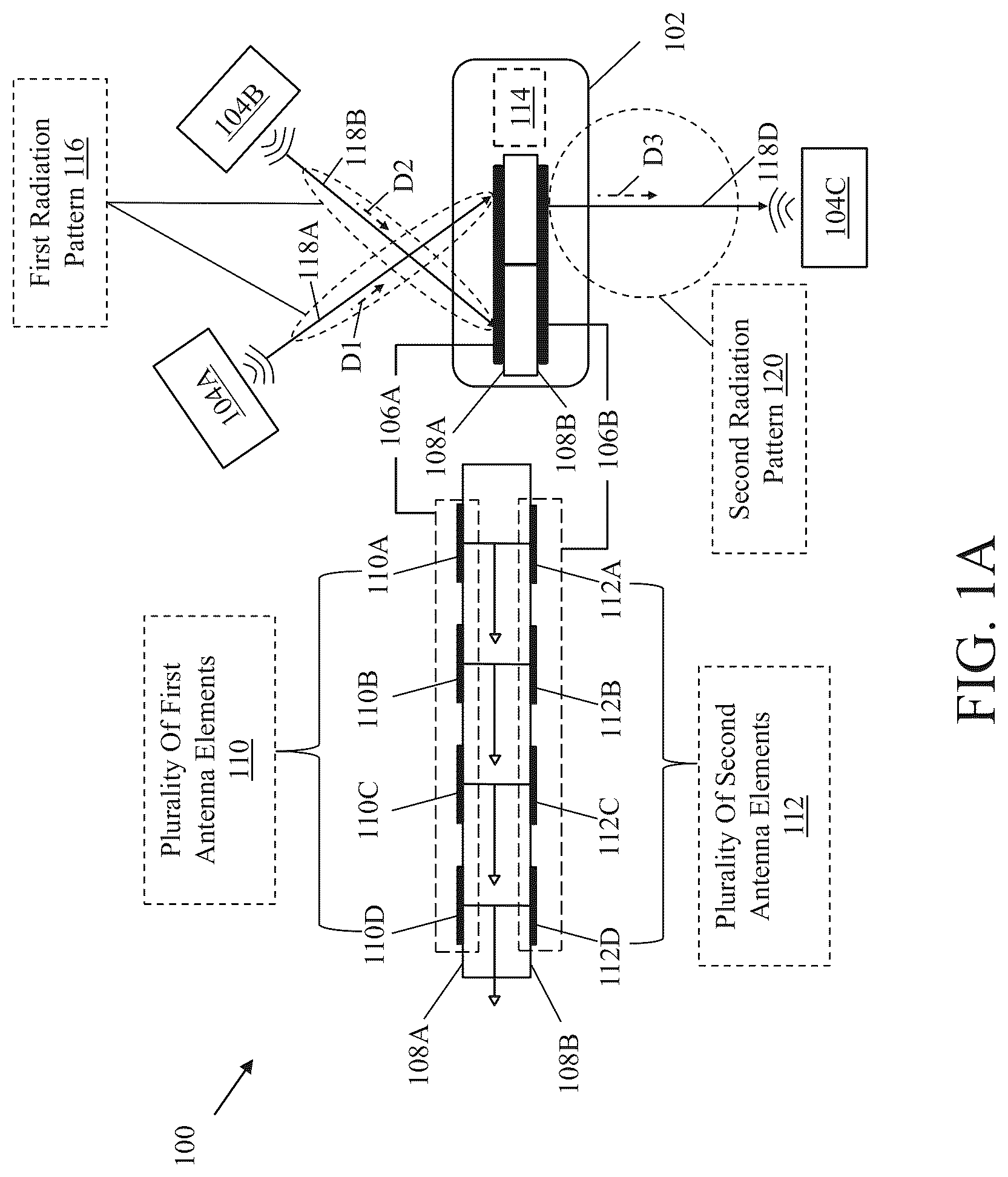
A is a diagram that illustrates a network environment of an exemplary repeater device for non-line-of-sight communication, in accordance with an exemplary embodiment of the disclosure. With reference to A , there is shown a network environment 100 A that includes a repeater device 102 and a plurality of network nodes, such as a first network node 104 A, a second network node 104 B, and a third network node 104 C. A is described by taking an example of a downlink communication scenario.
The repeater device 102 includes suitable logic, circuitry, and interfaces that may be configured to communicate with various network nodes, such as the first network node 104 A, the second network node 104 B, and the third network node 104 C. The repeater device 102 may be a passive repeater device that establishes wireless communication between two network nodes that are in a non-line-of-sight. The repeater device 102 enables data communication at a multi-gigabit data rate. In accordance with an embodiment, the repeater device 102 may support multiple and a wide range of frequency spectrum, for example, 3G, 4G, and 5G (including out-of-band frequencies). Examples of the repeater device 102 may include, but are not limited to, an XG wireless access point, an XG-enabled passive repeater device, an XG-enabled window-mounted communication device, an XG-enabled wall-mounted communication device, an evolved-universal terrestrial radio access-new radio (NR) dual connectivity (EN-DC) repeater device, an NR-enabled cellular repeater device, a wireless local area network (WLAN)-enabled device, a home router, a MIMO-capable repeater device, or a combination thereof, where “XG” refers to 5G or 6G.
In this case, the first network node 104 A and the second network node 104 B refer to base stations, small cells, or another repeater device, for example, similar to the repeater device 102 . Examples of the first network node 104 A and the second network node 104 B may include, but are not limited to, base stations (e.g., Evolved Nodes B (eNB) or gNB), small cells, remote radio units (RRU), or other network nodes or communication devices provided in a network.
The third network node 104 C refers to a user equipment (UE) (for example, an end-user device), a customer premise equipment (CPE), or another network node. Examples of the UE or the CPE may include, but are not limited to, a smartphone, a virtual reality headset, an augmented reality device, a cable or satellite television set-top box, a VoIP base station, or any other customized hardware for telecommunication.
The repeater device 102 includes a first antenna array 106 A and a second antenna array 106 B. The first antenna array 106 A is arranged on a first surface 108 A in the repeater device 102 and the second antenna array 106 B is arranged on a second surface 108 B, opposite to the first surface 108 A. The first surface 108 A may be a surface of a printed circuit board (PCB) and a first side of the repeater device 102 facing the base stations (e.g., the first network node 104 A and the second network node 104 B in this A ). The second surface 108 B may be the other surface of the PCB and a second side of the repeater device 102 facing one or more UEs (e.g., the third network node 104 C in this case), where the second side is opposite the first side. Each of the first antenna array 106 A and the second antenna array 106 B may refer to one of a single-polarized array, a dual polarized array, or a circularly polarized array. Examples of the first antenna array 106 A and the second antenna array 106 B may include, but are not limited to, an XG phased-array antenna panel, an XG-enabled antenna chipset, an XG-enabled patch antenna array, where “XG” refers to 5G or 6G.
The first antenna array 106 A may include a plurality of first antenna elements 110 that are arranged on the first surface 108 A of the repeater device 102 . In this exemplary implementation, the first antenna array 106 A is described by taking an example of a 1×4 antenna array of 4 antenna elements, such as first antenna elements 110 A- 110 D arranged on the first surface 108 A. It is to be understood by one of ordinary skill in the art that the 1×4 antenna array is described for exemplary purpose and that different sizes of antenna array (for example, N×N antenna array) may be employed. In other words, in an actual implementation, the plurality of first antenna elements 110 may include less than four or more than four antenna elements and the first antenna array 106 A may be a one-dimension antenna array or a two-dimension antenna array.
The second antenna array 1068 may include a plurality of second antenna elements 112 that are arranged on the second surface 1088 of the repeater device 102 . In this exemplary implementation, the second antenna array 106 B is described by taking an example of a 1×4 antenna array of 4 antenna elements, such as second antenna elements 112 A- 112 D arranged on the second surface 108 B. It is to be understood by one of ordinary skill in the art that the 1×4 antenna array is described for exemplary purpose and that different sizes of antenna array (for example, N×N antenna array) may be employed. In other words, in an actual implementation, the plurality of second antenna elements 112 may include less than four or more than four antenna elements and the second antenna array 106 B may be a one dimension antenna array or a two dimension antenna array.
Each first antenna element of the plurality of first antenna elements 110 on the first surface 108 A may be coupled to at least one second antenna element of the plurality of second antenna elements 112 on the second surface 1088 . In one example, each first antenna element of the plurality of first antenna elements 110 on the first surface 108 A may be coupled (i.e., electrically and conductively coupled) to an independent second antenna element of the plurality of second antenna elements 112 on the second surface 1088 . For example, as shown in A , the first antenna elements 110 A to 110 D on the first surface 108 A are coupled to the second antenna elements 112 A to 112 D on the second surface 1088 , respectively. In another example, each single independent antenna on the first surface 108 A at one side of the repeater device 102 may be connected (i.e., electrically and conductively coupled) to a corresponding single antenna element or a subarray of antenna elements on the second surface 1088 at the other side in order relay a RF signal to different (or same) direction on the other side.
In accordance with an embodiment, the repeater device 102 may comprise control circuitry 114 that may be communicatively coupled to the first antenna array 106 A and the second antenna array 106 B. The control circuitry 114 may be configured to execute various operations of the repeater device 102 . Examples of the implementation of the control circuitry 114 may include but are not limited to an embedded processor, a microcontroller, a specialized digital signal processor (DSP), a Reduced Instruction Set Computing (RISC) processor, an Application-Specific Integrated Circuit (ASIC) processor, a Complex Instruction Set Computing (CISC) processor, and/or other processors, or state machines.
In operation, the first network node 104 A and the second network node 104 B (e.g., two base stations) functioning as source nodes may not be in a line-of-sight of the third network node 104 C (e.g., a UE) functioning as a destination node. Thus, the repeater device 102 , which is a passive repeater device, may be used to establish wireless communication between the third network node 104 C and one of the first network node 104 A and the second network node 104 B. The repeater device 102 may include a PCB such that the first side (e.g., the first surface 108 A) of the PCB that faces the first network node 104 A and the second network node 104 B may be mounted with the plurality of first antenna elements 110 , and the other side (e.g., the second surface 108 B) opposite to the first side and facing the third network node 104 C may be mounted with the plurality of second antenna elements 112 . Each first antenna element of the plurality of first antenna elements 110 on the first surface 108 A may be connected (i.e., electrically and conductively coupled) to a corresponding second antenna element (or a subarray of second antenna elements) of the plurality of second antenna elements 112 on the second surface 108 B. In an example, the connection between the plurality of first antenna elements 110 on the first surface 108 A and the plurality of second antenna elements 112 on the second surface 108 B may be formed by placing RF trace through via holes in the PCB. The connection between the plurality of first antenna elements 110 on the first surface 108 A and the plurality of second antenna elements 112 enables RF signals to be relayed from the first side to the second side in a same or different direction.
The plurality of first antenna elements 110 are configured to potentially receive two or more beams of radio frequency (RF) signals in a first radiation pattern 116 (e.g. a narrow beam pattern) from different directions. For example, as shown in A , a first beam of RF signal 118 A in the first radiation pattern 116 arrives at the repeater device 102 from a first direction D 1 from the first network node 104 A and a second beam of RF signal 1188 in the first radiation pattern 116 arrives at the repeater device 102 from a second direction D 2 from the second network node 104 B. The control circuitry 114 may be configured to select at least one first antenna element of the plurality of first antenna elements 110 and the corresponding second antenna element of the plurality of second antenna elements 112 based on a direction of signal reception with respect to the first antenna array 106 A. Thus, instead of performing extreme beam forming using the first antenna array 106 A, the control circuitry 114 selectively activates at least one first antenna element of the plurality of first antenna elements 110 and the corresponding second antenna element of the plurality of second antenna elements 112 to receive from an appropriate direction, an incoming beam of RF signal.
In an example, a signal strength of the first beam of RF signal 118 A may be stronger than a signal strength of the second beam of RF signal 1188 . In such a scenario, the control circuitry 114 may be configured to select at least one of the plurality of first antenna elements 110 that corresponds to the first direction D 1 from which the first beam of RF signal 118 A with a stronger signal strength is received. However, if the signal strength of the second beam of RF signal 1188 becomes stronger than the signal strength of the first beam of RF signal 118 A, the control circuitry 114 may be configured to switch to another first antenna element of the plurality of first antenna elements 110 that corresponds to the second direction D 2 from which the second beam of RF signal 1188 is being received. In this case, both the first beam of RF signal 118 A the second beam of RF signal 1188 may be mmWave signals of same service provider but with different signal strengths.
In another example, the first beam of RF signal 118 A may correspond to a first service provider and the second beam of RF signal 1188 may correspond to a second service provider, and the third network node 104 C may be associated with the first service provider. In such a scenario, the control circuitry 114 may be configured to select at least one of the plurality of first antenna elements 110 that corresponds to the first direction D 1 from which the first beam of RF signal 118 A corresponding to the first service provider is being received. However, if the recipient of the wireless communication changes to another network node associated with the second service provider, the control circuitry 114 may be configured to switch to another first antenna element of the plurality of first antenna elements 110 that corresponds to the second direction D 2 from which the second beam of RF signal 118 B associated with the second service provider is being received.
In another example, the first beam of RF signal 118 A may be a 5G wireless signal and the second beam of RF signal 1188 may be a 4G wireless signal. In such a scenario, the control circuitry 114 may be configured to select at least one of the plurality of first antenna elements 110 that corresponds to the first direction D 1 from which the first beam of RF signal 118 A is being received. However, if the third network node 104 C is not 5G enabled, the control circuitry 114 may be configured to switch to another first antenna element of the plurality of first antenna elements 110 that corresponds to the second direction D 2 from which the second beam of RF signal 1188 is being received.
Thus, depending on one or more parameters of the first beam of RF signal 118 A and the second beam of RF signal 1188 , and a requirement of the third network node 104 C, the control circuitry 114 may be configured to select at least one first antenna element of the plurality of first antenna elements 110 and the corresponding second antenna element of the plurality of second antenna elements 112 .
For the sake of brevity, it is assumed that the control circuitry 114 selects the first antenna element 110 A and the corresponding second antenna element 112 A based on the first direction D 1 of the first beam of RF signal 118 A with respect to the first antenna array 106 A. It is to be understood that the A is explained by taking an example of the first direction D 1 . However, another first antenna element of the plurality of first antenna elements 110 and the corresponding second antenna element of the plurality of second antenna elements 112 may be selected based on another direction, such as the second direction D 2 , with respect to the first antenna array 106 A.
In accordance with an embodiment, only the first antenna element 110 A and the corresponding second antenna element 112 A that are selected may be activated, while all remaining first antenna elements 110 B- 110 D of the plurality of first antenna elements 110 on the first surface 108 A and all remaining second antenna elements 112 B- 112 D of the plurality of second antenna elements 112 may be deactivated. In other words, based on the selected at least one first antenna element of the plurality of first antenna elements 110 and the corresponding second antenna element of the plurality of second antenna elements 112 , the selected at least one first antenna element of the plurality of first antenna elements 110 and the corresponding second antenna element of the plurality of second antenna elements 112 are activated, while remaining first antenna elements 110 B- 110 D of the plurality of first antenna elements 110 and remaining second antenna elements 112 B- 112 D of the plurality of second antenna elements 112 may be deactivated. Moreover, power (current) may be fed to the first antenna array 106 A and the second antenna array 1068 such that only the selected first antenna element of the plurality of first antenna elements 110 and the corresponding second antenna element of the plurality of second antenna elements 112 are activated.
The control circuitry 114 may be further configured to control the selected first antenna element 110 A on the first surface 108 A to receive the first beam of RF signal 118 A in the first radiation pattern 116 from the first network node 104 A in the first direction D 1 . The selected first antenna element 110 A on the first surface 108 A may be configured to provide the received first beam of RF signal 118 A to the second antenna element 112 A coupled to the selected first antenna element 110 A on the second surface 1088 . The control circuitry 114 may be further configured to transmit received first beam of RF signal 118 C in a second radiation pattern 120 to the third network node 104 C in a third direction D 3 from the selected second antenna element 112 A coupled to the selected first antenna element 110 A. The second radiation pattern 120 may be broader than the first radiation pattern 116 . For example, the first radiation pattern 116 may be a narrow beam pattern and the second radiation pattern 120 may be a broad beam pattern.
The third network node 104 C may be configured to receive the transmitted beam of RF signal 118 C. In other words, the third network node 104 C which is not in the line-of-sight of the first network node 104 A is able to wirelessly communication with the first network node 104 A by the repeater device 102 . Thus, the repeater device 102 establishes a wireless communication between the first network node 104 A and the third network node 104 C by selectively receiving from the first network node 104 A, the first beam of RF signal 118 A in the first radiation pattern 116 (e.g., a narrow beam) and in the first direction D 1 from among the two or more beams of RF signals (such as the first beam of RF signal 118 A and the second beam of RF signal 118 B) that arrive at the repeater device 102 from the different directions (such as the first direction D 1 and the second direction D 2 ) and re-transmitting the received first beam of RF signal 118 A as the beam of RF signal 118 C in the second radiation pattern 120 (e.g., a broad beam) in the third direction D 3 to the third network node 104 C. For example, the first network node 104 A may be a gNB located far away from the repeater device 102 . Although multiple narrow beams (e.g., the first beam of RF signal 118 A and the second beam of RF signal 118 B in the first radiation pattern 116 ) arrive from different directions (e.g., the first direction D 1 and the second direction D 2 ) at one side (e.g., the first surface 108 A side) of the repeater device 102 , only the narrow beam (e.g., the first beam of RF signal 118 A) received from the first network node 104 A is allowed to pass to the other side (e.g., the second surface 108 B side) of the repeater device 102 as a broad beam (e.g., the beam of RF signal 118 C in the second radiation pattern 120 ). This selective transmission of a broad beam RF signal by the repeater device 102 increases the coverage for one or more UEs that are in communication with the repeater device 102 , without the need of extreme beam forming at the repeater device 102 , thereby improving on latency, computational resources usage, and power consumption (i.e., reduces power consumption) at the repeater device 102 . Here, the repeater device 102 may be a passive repeater that leverages antenna arrangement techniques (for example, arrangement of the plurality of first antenna elements 110 on the first surface 108 A and the plurality of second antenna elements 112 on the second surface 108 B) for transforming a narrow beam RF signal received at one side of the repeater device 102 to a broad beam RF signal transmitted from the opposite side, unlike active repeaters that heavily rely only on signal processing techniques for such transformation.
In accordance with an embodiment, the repeater device 102 may be deployed outdoors (e.g., at corner of a building, over the building, a street corner, under a bridge or a tunnel) to establish non-line-of-sight wireless communication between two network nodes that are outdoors. In accordance with another embodiment, the repeater device 102 may be deployed indoors (e.g., in interior of a building) to establish non-line-of-sight wireless communication between two network nodes that are indoors. In accordance with an embodiment, the repeater device 102 may be deployed outdoors or indoors (for example, on a glass of a window) to establish non-line-of-sight wireless communication between two network nodes of which one is indoors and the other is outdoors.
B is a diagram that illustrates a network environment of an exemplary repeater device for non-line-of-sight communication, in accordance with another exemplary embodiment of the disclosure. B is described in conjunction with elements from A . With reference to B , there is shown a network environment 100 that includes the repeater device 102 and the plurality of network nodes, such as the first network node 104 A, the second network node 104 B, and the third network node 104 C. B is described by taking an example of an uplink communication scenario. In the uplink communication scenario, the plurality of first antenna elements 110 are configured to potentially transmit two or more beams of RF signals in the first radiation pattern 116 towards different directions, such as directions D 1 ′ and D 2 ′.
In operation, the third network node 104 C may be a UE, which may not be in a line-of-sight of the first network node 104 A (e.g., a first base station) or the second network node 104 B (e.g., a second base station). Thus, the repeater device 102 , which is a passive repeater device, may be used to establish wireless communication between the third network node 104 C and one of the first network node 104 A and the second network node 1048 .
The control circuitry 114 may be configured to select at least one first antenna element of the plurality of first antenna elements 110 and the corresponding second antenna element of the plurality of second antenna elements 112 based on a direction of signal transmission with respect to the first antenna array 106 A.
In an example, the first network node 104 A may be nearer to the repeater device 102 than the second network node 104 B. In such a scenario, the control circuitry 114 may be configured to select at least one of the plurality of first antenna elements 110 that corresponds to the direction D 1 ′ associated with the first network node 104 A.
In another example, the first network node 104 A may be 5G enabled whereas the second network node 1048 may be 4G enabled. In such a scenario, the control circuitry 114 may be configured to select at least one of the plurality of first antenna elements 110 that corresponds to the direction D 1 ′ when the third network node 104 C is 5G enabled. However, if the third network node 104 C is not 5G enabled, the control circuitry 114 may be configured to switch to another first antenna element of the plurality of first antenna elements 110 that corresponds to the direction D 2 ′ of the 4G enabled second network node 1048 .
In another example, the first network node 104 A may correspond to a first service provider and the second network node 1048 may correspond to a second service provider, and the third network node 104 C may be associated with the first service provider. In such a scenario, the control circuitry 114 may be configured to select at least one of the plurality of first antenna elements 110 that corresponds to the direction D 1 ′ of the first network node 104 A. However, if the source network node (e.g., the third network node 104 C) switches to the second service provider, the control circuitry 114 may be configured to switch to another first antenna element of the plurality of first antenna elements 110 that corresponds to the direction D 2 ′ of the second network node 104 B.
Thus, depending upon a requirement of the third network node 104 C, the control circuitry 114 may be configured to select at least one first antenna element of the plurality of first antenna elements 110 and the corresponding second antenna element of the plurality of second antenna elements 112 .
For the sake of brevity, it is assumed that the control circuitry 114 selects the first antenna element 110 A and the corresponding second antenna element 112 A based on the direction D 1 ′ of signal transmission with respect to the first antenna array 106 A. It is to be understood that the B is explained by taking an example of the direction D 1 ′. However, another first antenna element of the plurality of first antenna elements 110 and the corresponding second antenna element of the plurality of second antenna elements 112 may be selected based on another direction of signal transmission, such as the direction D 2 ′, with respect to the first antenna array 106 A.
In accordance with an embodiment, only the first antenna element 110 A and the corresponding second antenna element 112 A that are selected may be activated, while all remaining first antenna elements 110 B- 110 D of the plurality of first antenna elements 110 on the first surface 108 A and all remaining second antenna elements 112 B- 112 D of the plurality of second antenna elements 112 may be deactivated. In other words, based on the selected at least one first antenna element of the plurality of first antenna elements 110 and the corresponding second antenna element of the plurality of second antenna elements 112 , the selected at least one first antenna element of the plurality of first antenna elements 110 and the corresponding second antenna element of the plurality of second antenna elements 112 are activated, while remaining first antenna elements 110 B- 110 D of the plurality of first antenna elements 110 and remaining second antenna elements 112 B- 112 D of the plurality of second antenna elements 112 may be deactivated. Moreover, power (current) may be fed to the first antenna array 106 A and the second antenna array 106 B such that only the selected first antenna element of the plurality of first antenna elements 110 and the corresponding second antenna element of the plurality of second antenna elements 112 are activated.
The control circuitry 114 may be further configured to control the selected second antenna element 112 A on the second surface 1088 to receive a third beam of RF signal 118 D in the second radiation pattern 120 from the third network node 104 C in the fourth direction D 3 ′. The fourth direction D 3 ′ refers to a direction that is opposite to the third direction D 3 (of A ). The selected second antenna element 112 A on the second surface 108 B may be configured to provide the received third beam of RF signal 118 D to the selected first antenna element 110 A on the first surface 108 A that is coupled to the selected second antenna element 112 A on the second surface 1088 . The control circuitry 114 may be further configured to transmit a received beam of RF signal 118 E in the first radiation pattern 116 to the first network node 104 A in a fifth direction D 1 ′ from the selected first antenna element 110 A. Here, the fifth direction D 1 ′ may be a direction that is opposite to the first direction D 1 (of A ). The second radiation pattern 120 may be broader than the first radiation pattern 116 . For example, the first radiation pattern 116 may be a narrow beam pattern and the second radiation pattern 120 may be a broad beam pattern.
The first network node 104 A may be configured to receive the transmitted beam of RF signal 118 E. In other words, the third network node 104 C which is not in the line-of-sight of the first network node 104 A is able to wirelessly communicate with the first network node 104 A by the repeater device 102 . Thus, the repeater device 102 establishes a wireless communication between the first network node 104 A and the third network node 104 C by receiving from the third network node 104 C, the third beam of RF signal 118 D in the second radiation pattern 120 and in the fourth direction D 3 ′, and selectively re-transmitting the received beam of RF signal 118 E in the first radiation pattern 116 and in the fifth direction D 1 ′ to the first network node 104 A.
is a block diagram illustrating various components of an exemplary repeater device, in accordance with an exemplary embodiment of the disclosure. With reference to , there is shown a block diagram 200 of the repeater device 102 . The repeater device 102 may include a control section 202 and a front-end radio frequency (RF) section 204 . The control section 202 may include the control circuitry 114 (as described in conjunction with A and 1 B ) and a memory 206 . The control section 202 may be communicatively coupled to the front-end RF section 204 . The front-end RF section 204 may include front-end RF circuitry 208 , the first antenna array 106 A and the second antenna array 106 B (of A and 1 B ), and a feeding network 210 .
The control circuitry 114 may be communicatively coupled to the first antenna array 106 A, the second antenna array 106 B, and the memory 208 . The control circuitry 114 may be configured to execute various operations of the repeater device 102 . The control circuitry 114 may be configured to control various components of the front-end RF section 204 . The repeater device 102 may be a programmable device, where the control circuitry 114 may execute instructions stored in the memory 206 .
The memory 206 may be configured to store various directions associated with the plurality of first antenna elements 110 . Examples of the implementation of the memory 206 may include, but not limited to, a random access memory (RAM), a dynamic random access memory (DRAM), a static random access memory (SRAM), a processor cache, a thyristor random access memory (T-RAM), a zero-capacitor random access memory (Z-RAM), a read only memory (ROM), a hard disk drive (HDD), a secure digital (SD) card, a flash drive, cache memory, and/or other non-volatile memory. It is to be understood by a person having ordinary skill in the art that the control section 202 may further include one or more other components, such as an analog to digital converter (ADC), a digital to analog (DAC) converter, a cellular modem, and the like, known in the art, which are omitted for brevity.
The front-end RF circuitry 208 may include receiver circuitry and transmitter circuitry. In an example, the receiver circuitry may include a cascading receiver chain comprising various components for baseband signal processing or digital signal processing. For example, the receiver circuitry may include a cascading receiver chain comprising various components (e.g., the one or more receiving antenna arrays, a set of low noise amplifiers (LNA), a set of receiver front end phase shifters, and a set of power combiners) for the signal reception (not shown for brevity). In an example, transmitter circuitry may include a cascading transmitter chain comprising various components for baseband signal processing or digital signal processing. The receiver circuitry may be coupled to the first antenna array 106 A and the second antenna array 106 B in an implementation. The transmitter circuitry may be coupled to the first antenna array 106 A and the second antenna array 106 B in an implementation. The front-end RF circuitry 208 may support millimeter-wave (mmWave) communication as well communication at a sub 6 gigahertz (GHz) frequency.
The feeding network 210 may define a distribution of conductive RF routings that couple the first antenna array 106 A to the second antenna array 106 B. For example, the feeding network 210 may be implemented in such a manner to ensure sufficient isolation between the first antenna array 106 A and the second antenna array 106 B. For example, the first antenna array 106 A and the second antenna array 106 B may be connected to a ground terminal to implement isolation between the first antenna array 106 A and the second antenna array 106 B.
A and 3 B are diagrams that illustrate exemplary operations of a repeater device, in accordance with an exemplary embodiment of the disclosure. A and 3 B are explained in conjunction with elements from A and 2 .
With reference to A , there is shown an exemplary scenario 300 A that illustrates operation of the repeater device 102 . Multiple beams of radio frequency (RF) signal 306 A, 306 B, 306 C, and 306 D in the first radiation pattern 116 (e.g., a narrow beam pattern) may arrive at the repeater device 102 from different network nodes 302 A, 302 B, 302 C, and 302 D in different directions. The network nodes 302 A, 302 B, 302 C, and 302 D are similar to the first network node 104 A and the second network node 104 B described in A .
In an example, the control circuitry 114 may be configured to selectively receive the beam of RF signal 306 A in the first radiation pattern 116 from the network node 302 A by selecting the first antenna element 110 A from the plurality of first antenna elements 110 on the first surface 108 A and re-transmit the received beam of RF signal 308 in the second radiation pattern 120 by the second antenna element 112 A that is on the second surface 108 B and coupled to the selected first antenna element 110 A to a network node 304 A. The network node 304 A is similar to the third network node 104 C.
Though the other beams of RF signal 306 B. 306 C, and 306 D arrive at the repeater device 102 , the other beams of RF signal 306 B. 306 C, and 306 D are not received by the first antenna elements 110 B, 110 C, and 110 D that are deactivated. Since the first antenna elements 110 B, 110 C, and 110 D do not receive the other beams of RF signal 306 B. 306 C, and 306 D, no power is transmitted to the corresponding second antenna elements 112 B, 112 C, and 112 D on the second surface 108 B. Thus, the second antenna elements 112 B, 112 C, and 112 D do not transmit any beam of RF signal.
With reference to B , there is shown an exemplary scenario 300 B that illustrates the operation of the repeater device 102 . In accordance with an embodiment, the multiple beams of RF signal 306 A, 306 B, 306 C, and 306 D in the first radiation pattern 116 arriving at the repeater device 102 from different network nodes 302 A, 302 B, 302 C, and 302 D in different directions may have different operating frequencies. In such an embodiment, the control circuitry 114 may be configured to simultaneously select two or more first antenna elements of the plurality of first antenna elements 110 based on the direction of the signal reception with respect to the first antenna array 106 A and the frequency of signal reception.
For example, as shown in B , the control circuitry 114 may be configured to selectively receive the beam of RF signal 306 A having the first radiation pattern 116 and a first frequency from the network node 302 A by selecting the first antenna element 110 A from the plurality of first antenna elements 110 on the first surface 108 A and re-transmit the received beam of RF signal 308 in the second radiation pattern 120 (e.g., a broad beam pattern) by the second antenna element 112 A that is on the second surface 1088 and coupled to the selected first antenna element 110 A. The control circuitry 114 may be further configured to selectively receive the beam of RF signal 306 D having the first radiation pattern 116 and a second frequency from the network node 302 D by selecting the first antenna element 110 D from the plurality of first antenna elements 110 on the first surface 108 A and re-transmit the received beam of RF signal 310 in the second radiation pattern 120 by the second antenna element 112 D that is on the second surface 1088 and coupled to the selected first antenna element 110 D. Thus, the repeater device 102 is capable of concurrently establishing a wireless communication between the network node 302 A and the network node 304 A at the first frequency and a wireless communication between the network node 302 D and the network node 304 B at the second frequency, where the first frequency is different from the second frequency. Here, the network node 304 B is similar to the third network node 104 C described in A .
In accordance with an embodiment, the control circuitry 114 may be further configured to simultaneously select two or more first antenna elements of the plurality of first antenna elements 110 and corresponding second antennal elements of the plurality of second antenna elements 112 based on the direction of the signal reception with respect to the first antenna array 106 A. For example, when a beam of RF signal in the first radiation pattern 116 arrives at the repeater device 102 from a direction that lies between beam forming directions of two or more first antenna elements of the plurality of first antenna elements 110 , the control circuitry 114 may be configured to simultaneously select the two or more first antenna elements of the plurality of first antenna elements 110 and the corresponding second antennal elements of the plurality of second antenna elements 112 for wireless communication.
A is a diagram that illustrates an exemplary repeater device, in accordance with another exemplary embodiment of the disclosure. A is explained in conjunction with elements from A and 2 . With reference to A , there is shown a repeater device 402 A. The repeater device 402 A is similar to the repeater device 102 except the repeater device 402 A includes a first plurality of switches 404 (for example, a first switch 404 A, a second switch 404 B, a third switch 404 C, and a fourth switch 404 D) and one or more power sources, such as a power source 406 . In accordance with an embodiment, the first plurality of switches 404 may be implemented on the second antenna array 106 B side. The first plurality of switches 404 may be configured to couple the plurality of first antenna elements 110 to the plurality of second antenna elements 112 . For example, the first switch 404 A may be configured to couple the first antenna element 110 A to the second antenna element 112 A and the second switch 404 B may be configured to couple the first antenna element 110 B to the second antenna element 112 B. Similarly, the third switch 404 C may be configured to couple the first antenna element 110 C to the second antenna element 112 C and the fourth switch 404 D may be configured to couple the first antenna element 110 D to the second antenna element 112 D. In accordance with an embodiment, the first plurality of switches 404 may refer to diodes.
The power source 406 may be configured to power the first plurality of switches 404 . Examples of the power source 406 may include, but are not limited to, a battery and a solar panel. The battery may be a Lithium ion battery, Nickel Cadmium battery, a supercapacitor, or the like.
The control circuitry 114 may be configured to control the first plurality of switches 404 by communicating one or more Bluetooth signals, low power LTE signals, Zigbee signals, or any other near field communication (NFC) signals. In accordance with an embodiment, coupling between the plurality of first antenna elements 110 and the plurality of second antenna elements 112 may be controlled by turning on or off the first plurality of switches 404 . For example, when the control circuitry 114 turns on the first switch 404 A and turns off all remaining switches of the first plurality of switches 404 , only the first antenna element 110 A remains coupled to the corresponding second antenna elements 112 A. In other words, only the first antenna element 110 A and the corresponding second antenna element 112 A are activated. Remaining first antenna elements 110 B, 110 C, and 11 D are decoupled from the corresponding second antenna elements 112 B, 112 C, and 112 D, and are thus deactivated.
In operation, the control circuitry 114 may be configured to activate a first set of switches of the first plurality of switches 404 and deactivate a second set of switches of the plurality of switches 404 based on the selected at least one first antenna element of the plurality of first antenna elements 110 . The first set of switches couples the selected at least one first antenna element on the first surface 108 A to the corresponding at least one second antenna element on the second surface 108 B. The second set of the switches couples remaining first antenna elements of the plurality of first antenna elements 110 on the first surface 108 A to corresponding second antenna elements of the plurality of second antenna elements 112 on the second surface 108 B. For example, if the control circuitry 114 selects the first antenna element 110 A and the corresponding second antenna element 112 A, the first set of switches that is activated (for example, turned on) includes the first switch 404 A and the second set of switches that is deactivated (for example, turned off) includes the second switch 404 b , the third switch 404 C, and the fourth switch 404 D.
B is a diagram that illustrates an exemplary repeater device, in accordance with another exemplary embodiment of the disclosure. B is explained in conjunction with elements from A, 2 , and 4 A . With reference to B , there is shown a repeater device 402 B. The repeater device 402 B is similar to the repeater device 402 A except the repeater device 402 B includes a second plurality of switches 408 (such as a fifth switch 408 E, a sixth switch 408 F, a seventh switch 408 G, and an eighth switch 408 H) implemented on the first antenna array 106 A side instead of the first plurality of switches 404 implemented on the second antenna array 106 B side. The operation of the second plurality of switches 408 is similar to the first plurality of switches 404 as described in A . For example, the fifth switch 408 A may be configured to couple the first antenna element 110 A to the second antenna element 112 A and the sixth switch 408 B may be configured to couple the first antenna element 110 B to the second antenna element 112 B. Similarly, the seventh switch 408 C may be configured to couple the first antenna element 110 C to the second antenna element 112 C and the eighth switch 408 D may be configured to couple the first antenna element 110 D to the second antenna element 112 D. In accordance with an embodiment, the second plurality of switches 408 may refer to diodes controlled by the control circuitry 114 for selective activation and deactivation of the plurality of first antenna elements 110 and the plurality of second antenna elements 112 .
C is a diagram that illustrates an exemplary repeater device, in accordance with another exemplary embodiment of the disclosure. C is explained in conjunction with elements from A, 2 , 4 A, and 4 B . With reference to C , there is shown a repeater device 402 C. The repeater device 402 C is similar to the repeater device 402 A and 402 B except the repeater device 402 C includes the first plurality of switches 404 implemented on the second antenna array 106 B side and the second plurality of switches 408 implemented on the first antenna array 106 A side. In accordance with an embodiment, the first plurality of switches 404 and the second plurality of switches 408 may refer to diodes controlled by the control circuitry 114 for selective activation and deactivation of the plurality of first antenna elements 110 and the plurality of second antenna elements 112 .
A and 5 B are diagrams that illustrate exemplary repeater devices, in accordance with another exemplary embodiment of the disclosure. A and 5 B are explained in conjunction with elements from A, 1 B, and 2 . With reference to A and 5 B , there are shown repeater devices 502 A and 502 B. The repeater devices 502 A and 502 B are similar to the repeater device 102 except the repeater devices 502 A and 502 B include focusing elements 504 A and 504 B, respectively, on the first antenna array 106 A side. The focusing elements 504 A and 504 B may be lens.
Referring now to A , the focusing elements 504 A may be a bi-convex lens, a plano-convex lens, and a concavo-convex. In the downlink communication scenario, the focusing element 504 A may be configured to receive multiple incoming beams of RF signal, such as the first beam of RF signal 118 A and the second beam of RF signal 118 B (of A ), from multiple network nodes, such as the first network node 104 A and the second network node 104 B (of A ), in the first radiation pattern 116 and focus the incoming beams of RF signal on to the first antenna array 106 A. In other words, the focusing element 504 A may be configured to receive the incoming first beam of RF signal 118 A (of A ) from the first network node 104 A (of A ) in the first radiation pattern 116 , and focus the first beam of RF signal 118 A on to the selected first antenna element 110 A.
In the uplink communication scenario, the focusing element 504 A may be configured to receive a beam of RF signal transmitted by the selected at least one first antenna element of the plurality of first antenna elements 110 and focus the received beam of RF signal in a direction of a destination network node. For example, the focusing element 504 A may be configured to receive the third beam of RF signal 118 E (of B ) transmitted by the selected first antenna element 110 A and focus the received third beam of RF signal 118 E in the fifth direction D 1 ′ of the first network node 104 A (of B ).
It will be understood by those of ordinary skill in the art that the focusing element 504 A may be implemented in the repeater devices 402 A, 402 B, and 402 C as well. In addition, another focusing element similar to the focusing element 504 A may be implemented on the second antenna array 106 B side as well without deviating from the scope of the disclosure. On the second antenna array 106 B side, the focusing element may be configured to either focus a beam of RF signal received from a network node on to the second antenna array 106 B or focus beams of RF signal transmitted by one or more second antenna elements of the plurality of second antenna elements 112 on to destination network nodes.
Referring now to B , the focusing element 504 B may be a planer lens that has a metal trace printed thereon. The metal trace may have a plurality of phase shifting elements 506 . The operation of the focusing element 504 B is similar to the operation of the focusing element 504 A of A .
A and 6 B are diagrams that illustrate exemplary repeater devices, in accordance with another exemplary embodiment of the disclosure. A and 6 B are explained in conjunction with elements from A, 1 B, and 2 . With reference to A and 6 B , there are shown repeater devices 602 A and 602 B. The repeater devices 602 A and 602 B are similar to the repeater device 102 except the repeater devices 602 A and 602 B include reflecting elements 604 A and 604 B, respectively, on the first antenna array 106 A side. The reflecting elements 604 A and 604 B may be reflectors or radiators. The repeater device 602 A with the reflecting element 604 A and the repeater device 602 B with the reflecting element 604 B may be used instead of the repeater devices 102 , 402 A, 402 B, 402 C, and 502 when a line-of-sight between source nodes and the repeater device is obstructed.
Referring now to A , the reflecting element 604 A may be a curved metal reflector. In the downlink communication scenario, the reflecting element 604 A may be configured to receive multiple incoming beams of RF signal, such as the first beam of RF signal 118 A and the second beam of RF signal 1188 (of A ), from multiple network nodes, such as the first network node 104 A and the second network node 1048 (of A ) in the first radiation pattern 116 , and direct the incoming beams of RF signal with the first radiation pattern 116 on to the first antenna array 106 A. In other words, the reflecting element 604 A may be configured to receive the incoming first beam of RF signal 118 A (of A ) from the first network node 104 A (of A ) in the first radiation pattern 116 , and direct the first beam of RF signal 118 A on to the selected first antenna element 110 A. Thus, the reflecting element 604 A changes a direction of incoming beam of RF signal in the first radiation pattern 116 so as to direct the incoming beam on to the selected at least one first antenna element of the plurality of first antenna elements 110 .
In the uplink communication scenario, the reflecting element 604 A may be configured to receive an incoming beam of RF signal transmitted by the selected at least one first antenna element of the plurality of first antenna elements 110 in the first radiation pattern 116 and direct the received beam of RF signal in a direction of a destination network node. For example, the reflecting element 604 A may be configured to receive a beam of RF signal transmitted by the selected first antenna element 110 A in the first radiation pattern 116 and direct the received beam of RF signal having the first radiation pattern 116 in the direction of the first network node 104 A.
In accordance with an embodiment, to achieve an angle of reflection that is different from angle of incidence at the reflecting element 604 A, the reflecting element 604 A may have a metal trace printed on reflecting side. The metal trace may have a plurality of phase shifting elements 606 (shown in B ) that cause the angle of reflection to be different from the angle of incidence.
Referring now to B , the reflecting element 604 B may be a planer printed metal reflector with the plurality of phase shifting elements 606 . The operation of the reflecting element 604 B is similar to the operation of the reflecting element 604 A of A .
A is a diagram that illustrates an arrangement of antenna elements of a repeater device, in accordance with an exemplary embodiment of the disclosure. A is described in conjunction with elements from A, 1 B, 2 , 3 A- 3 B, 4 A- 4 C, 5 , and 6 A- 6 B . With reference to A , there is shown a 1×N first antenna array 702 A arranged on a first surface 704 A (one side) in a repeater device (such as the repeater device 102 , 402 A, 402 B, 402 C, 502 , 602 A, or 602 B) and 1×N second antenna array 706 A arranged on a second surface 708 A (other side) opposite to the first surface 704 A. Each antenna element of the 1×N first antenna array 702 A on the first surface 704 A is coupled to an independent antenna element of the 1×N second antenna array 706 A on the second surface 708 A.
The connection between each antenna element of the 1×N first antenna array 702 A on the first surface 704 A and the corresponding antenna element of the 1×N second antenna array 706 A on the second surface 708 A is shown by hatched lines 710 A to 710 N. It is to be understood by a person of ordinary skill in the art that the hatched lines 710 A to 710 N are merely shown for illustration. In an actual implementation, the connection between each antenna element of the 1×N first antenna array 702 A on the first surface 704 A and the corresponding antenna element of the 1×N second antenna array 706 A on the second surface 708 A may be formed by placing RF trace through via holes in the PCB.
B is a diagram that illustrates an arrangement of antenna elements of a repeater device, in accordance with an exemplary embodiment of the disclosure. B is described in conjunction with elements from A . With reference to B , there is shown a 1×N first antenna array 702 B arranged on a first surface 704 B (one side of the repeater) in a repeater device (for example, the repeater device 102 of A ) and 2×N second antenna array 706 B arranged on a second surface 708 B (the other side of the repeater device) opposite to the first surface 704 B. The 2×N second antenna array 706 B arranged on the second surface 708 B may include a plurality of sub-arrays 712 A to 712 N arranged on the second surface 708 B such that each sub-array includes two or more second antenna elements of the 2×N second antenna array 706 B. For the sake of illustration, the 2×N second antenna array 706 B is shown to include ‘N’ sub-arrays 712 A to 712 N, each including two second antenna elements. However, it is to be understood that in an actual implementation, the second antenna array 706 B may be N×N and each sub-array of the plurality of sub-arrays 712 A to 712 N may include any number of second antenna elements.
Each antenna element of the 1×N first antenna array 702 B on the first surface 704 B is coupled to a sub-array (including at least two antenna elements of the 2×N second antenna array 706 B) of the plurality of sub-arrays 712 A to 712 N on the second surface 708 B. The connection between one antenna element of the 1×N first antenna array 702 B on the first surface 704 B to a corresponding sub-array of the plurality of sub-arrays 712 A to 712 N on the second surface 708 B is shown by hatched lines 714 A to 714 N. It is to be understood by a person of ordinary skill in the art that the hatched lines 714 A to 714 N are merely shown for illustration. In an actual implementation, the connection between one antenna element of the 1×N first antenna array 702 B on the first surface 704 B to the corresponding sub-array of the plurality of sub-arrays 712 A to 712 N on the second surface 708 B may be formed by placing RF trace through via holes in the PCB.
In such implementation, at least one first antenna element of the 1×N first antenna array 702 B on the first surface 704 B and the corresponding sub-array of the plurality of sub-arrays 712 A to 712 N on the second surface 708 B may be selected based on a direction of signal reception or signal transmission with respect to the 1×N first antenna array 702 B.
C is a diagram that illustrates an arrangement of antenna elements of a repeater device, in accordance with an exemplary embodiment of the disclosure. C is described in conjunction with elements from A . With reference to C , there is shown a 2×N first antenna array 702 C arranged on a first surface 704 C in a repeater device (for example, the repeater device 102 ) and 1×N second antenna array 706 C arranged on a second surface 708 C opposite to the first surface 704 C. The 2×N first antenna array 702 C arranged on the first surface 704 C may include a plurality of sub-arrays 716 A to 716 N arranged on the first surface 704 C such that each sub-array incudes two or more first antenna elements of the 2×N first antenna array 702 C. For the sake of illustration, the 2×N first antenna array 702 C is shown to include ‘N’ sub-arrays 716 A to 716 N, each including two first antenna elements. However, it is to be understood that in an actual implementation, each sub-array of the plurality of sub-arrays 716 A to 716 N may include any number of first antenna elements.
Each sub-array of the plurality of sub-arrays 716 A to 716 N on the first surface 704 C is coupled to an independent antenna element of the 1×N second antenna arrays 706 C on the second surface 708 C. The connection between each sub-array of the plurality of sub-arrays 716 A to 716 N on the first surface 704 C to the corresponding antenna element of the 1×N second antenna array 706 C on the second surface 708 C is shown by hatched lines 718 A to 718 N. It is to be understood by a person of ordinary skill in the art that the hatched lines 718 A to 718 N are merely shown for illustration. In an actual implementation, the connection between each sub-array of the plurality of sub-arrays 716 A to 716 N on the first surface 704 C to the corresponding second antenna element of the 1×N second antenna array 706 C on the second surface 708 C may be formed by placing RF trace through via holes in the PCB.
In such implementation, a sub-array of the plurality of sub-arrays 716 A to 716 N on the first surface 704 C and the corresponding at least one second antenna element of the 1×N second antenna array 706 C on the second surface 708 C may be selected based on a direction of signal reception or signal transmission with respect to the 2×N first antenna array 702 C.
D is a diagram that illustrates an arrangement of antenna elements of a repeater device, in accordance with an exemplary embodiment of the disclosure. D is described in conjunction with elements from A . With reference to D , there is shown a 2×N first antenna array 702 D arranged on a first surface 704 D in a repeater device (for example, the repeater device 102 ) and 2×N second antenna array 706 D arranged on a second surface 708 D opposite to the first surface 704 D. The 2×N first antenna array 702 D arranged on the first surface 704 D may include a plurality of first sub-arrays 720 A to 720 N arranged on the first surface 704 D such that each first sub-array incudes two or more first antenna elements of the 2×N first antenna array 702 D. The 2×N second antenna array 706 D arranged on the second surface 708 D may include a plurality of second sub-arrays 722 A to 722 N arranged on the second surface 708 D such that each second sub-array includes two or more second antenna elements of the 2×N second antenna array 706 D. For the sake of illustration, the 2×N first antenna array 702 D is shown to include ‘N’ first sub-arrays 720 A to 720 N, each including two first antenna elements and the 2×N second antenna array 706 D is shown to include ‘N’ second sub-arrays 722 A to 722 N, each including two second antenna elements. However, it is to be understood that in an actual implementation, each first sub-array of the plurality of first sub-arrays 720 A to 720 N and each second sub-array of the plurality of second sub-arrays 722 A to 722 N may include any number of first and second antenna elements.
Each first sub-array of the plurality of sub-arrays 720 A to 720 N on the first surface 704 D is coupled to a corresponding second sub-array of the plurality of second sub-arrays 722 A to 722 N on the second surface 708 D. The connection between each first sub-array of the plurality of sub-arrays 720 A to 720 N on the first surface 704 D to the corresponding second sub-array of the plurality of second sub-arrays 722 A to 722 N on the second surface 708 D is shown by hatched lines 724 A to 724 N. It is to be understood by a person of ordinary skill in the art that the hatched lines 724 A to 724 N are merely shown for illustration. In an actual implementation, the connection between each first sub-array of the plurality of sub-arrays 720 A to 720 N on the first surface 704 D and the corresponding second sub-array of the plurality of second sub-arrays 722 A to 722 N on the second surface 708 D may be formed by placing RF trace through via holes in the PCB.
In such implementation, a first sub-array of the plurality of first sub-arrays 720 A to 720 N on the first surface 704 D and the corresponding second sub-array of the plurality of second sub-arrays 722 A to 722 N on the second surface 708 D may be selected based on a direction of signal reception or signal transmission with respect to the 2×N first antenna array 702 D.
It is to be understood that the 2×N antenna array is merely shown for exemplary purpose. In an actual implementation, any N×N antenna array may be used to implement a first antenna array and a second antenna array of the repeater device of present disclosure. Further, it will be understood by a person of ordinary skill in the art that the arrangement of antenna elements as described in A, 7 B, 7 C, and 7 D may be implemented in any of the repeater devices 102 , 402 A, 402 B, 402 C, 502 , 602 A, or 602 B, without deviating from the scope of the disclosure.
is a diagram that illustrates an exemplary scenario for outdoor deployment of a repeater device, in accordance with an embodiment of the disclosure. is explained in conjunction with elements from A, 1 B, 2 , 4 A, 4 B, 5 , 6 A, 6 B, and 7 A to 7 D . With reference to , there is shown in an exemplary scenario 800 where a repeater device 802 is deployed outdoors around a corner of a building 804 A to establish wireless communication between network nodes, such as network nodes 806 and 808 , that are outdoors and have their line of sight obstructed due to presence of buildings 804 A, 804 B, and 804 C or other obstructions. In such scenario, the repeater device 802 establishes a wireless communication between non-line-of-sight network nodes, such as the network nodes 806 and 808 , without the requirement of extreme beam forming towards any of the network nodes 806 and 808 .
The network nodes 806 and 808 are similar to the first network node 104 A, the second network node 104 B, and the third network node 104 C of A and 1 B. The repeater device 802 is similar to the repeater devices 102 , 402 A, 402 B, 402 C, 502 , 602 A, or 602 B.
is a diagram that illustrates an exemplary scenario for indoor deployment of a repeater device, in accordance with an embodiment of the disclosure. is explained in conjunction with elements from A, 1 B, 2 , 4 A, 4 B, 5 , 6 A, 6 B, and 7 A to 7 D . With reference to , there is shown in an exemplary scenario 900 where a repeater device 902 is deployed indoors around corners of rooms or passageways to establish wireless communication between network nodes, such as network nodes 904 and 906 , that are indoors and have their line of sight obstructed due to presence walls, such as walls 908 and 910 , or other obstructions. In such scenario, the repeater device 902 may be mounted on corner walls to establish a wireless communication between non-line-of-sight network nodes, such as the network nodes 904 and 906 , without the requirement of extreme beam forming at any of the network nodes 904 and 906 .
The network nodes 904 and 906 are similar to the first network node 104 A, the second network node 104 B, and the third network node 104 C of A and 1 B . The repeater device 902 can be any of the repeater devices 102 , 402 A, 402 B, 402 C, 502 , 602 A, or 602 B (of A and 1 B, 4 A, 4 B, 4 C, 5 , 6 A, and 6 B ).
is a diagram that illustrates an exemplary scenario for deployment of a repeater device for outdoor to indoor and indoor to outdoor communication, in accordance with an embodiment of the disclosure. is explained in conjunction with elements from A, 1 B, 2 , 4 A, 4 B, 5 , 6 A, 6 B, and 7 A to 7 D . With reference to , there is shown in an exemplary scenario 1000 where a repeater device 1002 is deployed on a window glass 1004 (indoors or outdoors), to establish wireless communication between network nodes, such as network nodes 1006 and 1008 , one of which is indoors and the other is outdoors, and have their line of sight obstructed.
The network nodes 1006 and 1008 are similar to the first network node 104 A, the second network node 104 B, and the third network node 104 C of A and 1 B. The repeater device 1002 can be any of the repeater devices 102 , 402 A, 402 B, 402 C, 502 , 602 A, or 602 B (of A and 1 B, 4 A, 4 B, 4 C, 5 , 6 A, and 6 B ).
is a diagram that illustrates simulation results indicating operation of a repeater device, in accordance with an embodiment of the disclosure. With reference to , there is shown a diagram 1100 that illustrates simulation results indicating operation of a repeater device 1102 . In this case, the repeater device 1102 may have a 1×8 first antenna array 1104 arranged on a first surface 1106 A (one side) and a 1×8 second antenna array 1108 arranged on a second surface 1106 B (other side) opposite to the first surface 1106 A. Each antenna element of the 1×8 first antenna array 1104 on the first surface 1106 A is coupled to an independent antenna element of the 1×8 second antenna array 1108 on the second surface 1106 B. In the diagram 1100 , for eight incoming beams of RF signals 1110 in the first radiation pattern 116 (e.g., 8 narrow beams), eight corresponding beams of RF signals 1112 in the second radiation pattern 120 (e.g., broad beams) may be generated. It is to be understood that in the , only 2-3 broad beams may be visible in the form of the beams of RF signals 1112 and shown for representation purposes, but 8 beams may be generated in practice.
is a flowchart that illustrates a method of operation of a repeater device for non-line-of-sight communication, in accordance with an embodiment of the disclosure. is explained in conjunction with elements from A, 1 B, 2 , 3 A, 3 B, 4 A, 4 B, 4 C, 5 , 6 A, 6 B, 7 A to 7 D, 8 , 9 , and 10 . With reference to , there is shown a flowchart 1200 comprising exemplary operations 1202 through 1206 .
At 1202 , at least one first antenna element of a plurality of first antenna elements (e.g., the plurality of first antenna elements 110 ) in a first antenna array (e.g., the first antenna array 106 A) on a first surface (e.g., the first surface 108 A) of a repeater device (e.g., the repeater device 102 , 402 A, 402 B, 402 C, 502 , 602 A, and 602 B, 802 , 902 , or 1002 ) and a corresponding at least one second antenna element of a plurality of second antenna elements (e.g., the plurality of second antenna elements 112 ) in a second antenna array (e.g., the second antenna array 106 B) on a second surface (e.g., the second surface 108 B) of the repeater device are selected based on a first direction of signal reception with respect to the first antenna array.
In an example, the first antenna element 110 A from the plurality of first antenna elements 110 on the first surface 108 A and the corresponding second antenna element 112 A from the plurality of second antenna elements 112 on the second surface 1088 may be selected when the first beam of RF signal 118 A in the first radiation pattern 116 is to be received from the first network node 104 A in the first direction D 1 . In another example, the first antenna element 1108 from the plurality of first antenna elements 110 on the first surface 108 A and the corresponding second antenna element 1128 from the plurality of second antenna elements 112 on the second surface 1088 may be selected when the second beam of RF signal 1188 in the first radiation pattern 116 is to be received from the second network node 1048 in the second direction D 2 .
At 1204 , the selected at least one first antenna element on the first surface is controlled to receive the beam of RF signal in the first radiation pattern from the first network node in the first direction. In an example, the selected at least one first antenna element 110 A on the first surface 108 A may be controlled to receive the first beam of RF signal 118 A in the first radiation pattern 116 from the first network node 104 A in the first direction D 1 .
At 1206 , the beam of RF signal is transmitted in a second radiation pattern to a second network node in a second direction from the at least one second antenna element coupled to the selected at least one first antenna element such that the second radiation pattern is broader than the first radiation pattern. In an example, the beam of RF signal 118 C is transmitted in the second radiation pattern 120 to the second network node (e.g., the third network node 104 C) in the second direction (e.g., the direction D 3 ) from the at least one second antenna element 112 A coupled to the selected at least one first antenna element 110 A such that the second radiation pattern 120 is broader than the first radiation pattern 116 .
is a flowchart that illustrates a method of operation of a repeater device for non-line-of-sight communication, in accordance with an embodiment of the disclosure. is explained in conjunction with elements from A, 1 B, 2 , 3 A, 3 B, 4 A, 4 B, 4 C, 5 , 6 A, 6 B, 7 A to 7 D, 8 , 9 , and 10 . With reference to , there is shown a flowchart 1300 comprising exemplary operations 1302 through 1306 .
At 1302 , at least one first antenna element of a plurality of first antenna elements (e.g., the plurality of first antenna elements 110 ) in a first antenna array (e.g., the first antenna array 106 A) on a first surface (e.g., the first surface 108 A) of a repeater device (e.g., the repeater device 102 , 402 A, 402 B, 402 C, 502 , 602 A, and 602 B, 802 , 902 , or 1002 ) and a corresponding at least one second antenna element of a plurality of second antenna elements (e.g., the plurality of second antenna elements 112 ) in a second antenna array (e.g., the second antenna array 106 B) on a second surface (e.g., the second surface 108 B) of the repeater device are selected based on a first direction of signal transmission with respect to the first antenna array.
In an example, the first antenna element 110 A from the plurality of first antenna elements 110 on the first surface 108 A and the corresponding second antenna element 112 A from the plurality of second antenna elements 112 on the second surface 108 B may be selected when the direction of signal transmission corresponds to the first network node 104 A in the first direction D 1 . In another example, the first antenna element 110 B from the plurality of first antenna elements 110 on the first surface 108 A and the corresponding second antenna element 112 B from the plurality of second antenna elements 112 on the second surface 108 B may be selected when the direction of signal transmission corresponds to the second network node 104 B in the second direction D 2 .
At 1304 , the selected at least one second antenna element on the second surface and coupled to the selected at least first antenna element is controlled to receive the beam of RF signal in a second radiation pattern from a first network node in a second direction. In an example, the selected at least one second antenna element 112 A on the second surface 108 B and coupled to the selected at least first antenna element 110 A may be controlled to receive the beam of RF signal 118 D in the second radiation pattern 120 from the third network node 104 C in the fourth direction D 3 ′.
At 1306 , the beam of RF signal is transmitted in a first radiation pattern to a second network node in the first direction from the selected at least one first antenna element such that the second radiation pattern is broader than the first radiation pattern. In an example, the beam of RF signal 118 E is transmitted in the first radiation pattern 116 to the second network node (e.g., the first network node 104 A) in the first direction (e.g., the direction D 1 ′) from the selected at least one first antenna element 110 A such that the second radiation pattern 120 is broader than the first radiation pattern 116 .
Various embodiments of the disclosure may provide a repeater device, for example, the repeater device 102 , 402 A, 402 B, 402 C, 502 , 602 A, and 602 B, 802 , 902 , or 1002 ). The repeater device 102 , 402 A, 402 B, 402 C, 502 , 602 A, and 602 B, 802 , 902 , or 1002 includes a first antenna array that is arranged on a first surface and comprises a plurality of first antenna elements. The plurality of first antenna elements are configured to potentially receive two or more beams of radio frequency (RF) signals in a first radiation pattern 116 from different directions. The repeater device 102 , 402 A, 402 B, 402 C, 502 , 602 A, and 602 B, 802 , 902 , or 1002 further includes a second antenna array that is arranged on a second surface opposite to the first surface and comprises a plurality of second antenna elements. Each first antenna element of the plurality of first antenna elements on the first surface is coupled to at least one second antenna element of the plurality of second antenna elements on the second surface. The repeater device 102 , 402 A, 402 B, 402 C, 502 , 602 A, and 602 B, 802 , 902 , or 1002 further includes control circuitry 114 configured to select at least one first antenna element of the plurality of first antenna elements and a corresponding at least one second antenna element of the plurality of second antenna elements based on a first direction of signal reception with respect to the first antenna array. The control circuitry 114 is further configured to control the selected at least one first antenna element on the first surface to receive a beam of RF signal in the first radiation pattern from a first network node in the first direction. The control circuitry 114 is further configured to transmit the beam of RF signal in a second radiation pattern 120 to a second network node in a second direction from the at least one second antenna element coupled to the selected at least one first antenna element such that the second radiation pattern 120 is broader than the first radiation pattern 116 .
Various embodiments of the disclosure may provide a repeater device, for example, the repeater device 102 , 402 A, 402 B, 402 C, 502 , 602 A, and 602 B, 802 , 902 , or 1002 ). The repeater device 102 , 402 A, 402 B, 402 C, 502 , 602 A, and 602 B, 802 , 902 , or 1002 includes a first antenna array that is arranged on a first surface and comprises a plurality of first antenna elements. The plurality of first antenna elements are configured to potentially transmit two or more beams of radio frequency (RF) signals in a first radiation pattern towards different directions. The repeater device 102 , 402 A, 402 B, 402 C, 502 , 602 A, and 602 B, 802 , 902 , or 1002 further includes a second antenna array that is arranged on a second surface opposite to the first surface and comprises a plurality of second antenna elements. Each first antenna element of the plurality of first antenna elements on the first surface is coupled to at least one second antenna element of the plurality of second antenna elements on the second surface. The repeater device 102 , 402 A, 402 B, 402 C, 502 , 602 A, and 602 B, 802 , 902 , or 1002 further includes control circuitry 114 configured to select at least one first antenna element of the plurality of first antenna elements and a corresponding at least one second antenna element of the plurality of second antenna elements based on a first direction of signal transmission with respect to the first antenna array. The control circuitry 114 is further configured to control the at least one second antenna element that is on the second surface and coupled to the selected at least first antenna element, to receive a beam of RF signal in a second radiation pattern 120 from a first network node in a second direction. The control circuitry 114 is further configured to transmit the beam of RF signal in the first radiation pattern 116 to a second network node in the first direction from the selected at least one first antenna element on the first surface, such that the first radiation pattern 116 is narrower than the second radiation pattern 120 .
Various embodiments of the disclosure may provide a non-transitory computer-readable medium having stored thereon, computer-implemented instructions which when executed by a computer in a repeater device causes the repeater device to execute operations that may comprise selecting at least one first antenna element of a plurality of first antenna elements in a first antenna array on a first surface of the repeater device and a corresponding at least one second antenna element of a plurality of second antenna elements in a second antenna array on a second surface of the repeater device, where the selection of the at least one first antenna element on the first surface and the corresponding at least one second antenna element on the second surface is based on a first direction of signal reception with respect to the first antenna array, wherein the second surface is opposite to the first surface. The operations may further comprise controlling the selected at least one first antenna element on the first surface to receive a beam of radio frequency (RF) signal in a first radiation pattern from a first network node in a first direction. The operations may further comprise transmitting the beam of RF signal in a second radiation pattern to a second network node in a second direction from the at least one second antenna element coupled to the selected at least one first antenna element, where the second radiation pattern is broader than the first radiation pattern.
Various embodiments of the disclosure may provide a non-transitory computer-readable medium having stored thereon, computer-implemented instructions which when executed by a computer in a repeater device causes the repeater device to execute operations that may comprise selecting at least one first antenna element of a plurality of first antenna elements in a first antenna array on a first surface of the repeater device and a corresponding at least one second antenna element of a plurality of second antenna elements in a second antenna array on a second surface of the repeater device, where the selection of the at least one first antenna element on the first surface and the corresponding at least one second antenna element on the second surface is based on a first direction of signal reception with respect to the first antenna array, wherein the second surface is opposite to the first surface. The operations may further comprise controlling the selected at least one first antenna element on the first surface to receive a beam of radio frequency (RF) signal in a first radiation pattern from a first network node in a first direction. The operations may further comprise transmitting the beam of RF signal in a second radiation pattern to a second network node in a second direction from the at least one second antenna element coupled to the selected at least one first antenna element, where the second radiation pattern is broader than the first radiation pattern.
While various embodiments described in the present disclosure have been described above, it should be understood that they have been presented by way of example, and not limitation. It is to be understood that various changes in form and detail can be made therein without departing from the scope of the present disclosure. In addition to using hardware (e.g., within or coupled to a central processing unit (“CPU”), microprocessor, micro controller, digital signal processor, processor core, system on chip (“SOC”) or any other device), implementations may also be embodied in software (e.g. computer readable code, program code, and/or instructions disposed in any form, such as source, object or machine language) disposed for example in a non-transitory computer-readable medium configured to store the software. Such software can enable, for example, the function, fabrication, modeling, simulation, description and/or testing of the apparatus and methods describe herein. For example, this can be accomplished through the use of general program languages (e.g., C, C++), hardware description languages (HDL) including Verilog HDL, VHDL, and so on, or other available programs. Such software can be disposed in any known non-transitory computer-readable medium, such as semiconductor, magnetic disc, or optical disc (e.g., CD-ROM, DVD-ROM, etc.). The software can also be disposed as computer data embodied in a non-transitory computer-readable transmission medium (e.g., solid state memory any other non-transitory medium including digital, optical, analog-based medium, such as removable storage media). Embodiments of the present disclosure may include methods of providing the apparatus described herein by providing software describing the apparatus and subsequently transmitting the software as a computer data signal over a communication network including the internet and intranets.
It is to be further understood that the system described herein may be included in a semiconductor intellectual property core, such as a microprocessor core (e.g., embodied in HDL) and transformed to hardware in the production of integrated circuits. Additionally, the system described herein may be embodied as a combination of hardware and software. Thus, the present disclosure should not be limited by any of the above-described exemplary embodiments but should be defined only in accordance with the following claims and their equivalents.
Figures (20)
Citations
This patent cites (2)
- US20210280981
- USWO-0117059