Portable Terminal Apparatus and Wireless Power Transmission Method by Portable Terminal Apparatus
Abstract
A portable device comprising: an inter-device communication transceiver configured to receive, from at least one subordinate portable device that operates in accordance with control performed by the portable device, a power transfer request signal with respect to the subordinate portable device; a power transfer control circuit configured to transfer power to the subordinate portable device; a battery; and a controller configured to control an operation of the inter-device communication transceiver and an operation of the power transfer control circuit. The controller is further configured to: when the inter-device communication transceiver receives the power transfer request signal, detect a battery residual amount; and perform control for causing the power transfer control circuit and the inter-device communication transceiver to output electromagnetic waves for wireless power transfer in accordance with a detection result of the battery residual amount.
Claims (10)
1. A portable device-terminal comprising: a communication transceiver configured to receive, from at least one subordinate portable terminal that operates in accordance with control performed by the portable terminal, a power transfer request signal with respect to the subordinate portable terminal; a power transfer control circuit configured to transfer power to the subordinate portable terminal; a battery; and a controller configured to control an operation of the communication transceiver and an operation of the power transfer control circuit, where the controller is further configured to: when the communication transceiver receives the power transfer request signal, detect a battery residual amount charged in the battery, and perform control for causing the power transfer control circuit and the communication transceiver to output electromagnetic waves for wireless power transfer in accordance with a detection result of the battery residual amount, wherein the power transfer request signal includes a required amount of power requested by the subordinate portable device, and wherein the controller is further configured to: determine whether power transfer to the subordinate portable terminal can be performed based on a comparison result obtained by comparing the battery residual amount and the required amount of power with a power transfer lower allowable limit value used for determining whether the power transfer to the subordinate portable terminal can be performed, when determining that the power transfer to the subordinate portable terminal can be performed, output a power transfer instruction signal to the power transfer control circuit, when determining that power transfer that satisfies the required amount of power cannot be performed based on the comparison result obtained by comparing the battery residual amount and the required amount of power with the power transfer lower allowable limit value, calculate a transferrable amount of power which has a value smaller than the required amount of power and is allowable to be transferred to the subordinate portable terminal, and control the power transfer so as to transfer the transferrable amount of power to the subordinate portable terminal.
6. A wireless power transfer method by a portable terminal, comprising the steps of: receiving, by the portable terminal, from at least one subordinate portable terminal that operates in accordance with control by the portable terminal, a power transfer request signal with respect to the subordinate portable device terminal, the power transfer request signal including a required amount of power requested by the subordinate portable device; detecting, by the portable terminal, a battery residual amount charged in a battery provided in the portable device terminal; outputting, by the portable terminal, electromagnetic waves for transferring power to the subordinate portable terminal in accordance with a detection result of the battery residual amount; determining whether power transfer to the subordinate portable terminal can be performed based on a comparison result obtained by comparing the battery residual amount and the required amount of power with a power transfer lower allowable limit value used for determining whether the power transfer to the subordinate portable terminal can be performed; when determining that the power transfer to the subordinate portable terminal can be performed, outputting a power transfer instruction signal to the power transfer control circuit; when determining that power transfer that satisfies the required amount of power cannot be performed based on the comparison result obtained by comparing the battery residual amount and the required amount of power with the power transfer lower allowable limit value, calculating a transferrable amount of power which has a value smaller than the required amount of power and is allowable to be transferred to the subordinate portable terminal; and controlling the power transfer so as to transfer the transferrable amount of power to the subordinate portable terminal.
Show 8 dependent claims
2. The portable terminal device according to claim 1 , further comprising: an external communication transceiver configured to receive wireless power transfer waves; and a power reception control circuit configured to receive power with electromagnetic waves received via the external communication transceiver, wherein the controller is further configured to: when determining that the power transfer that satisfies the required amount of power cannot be performed, search for a wireless power transmitter that performs wireless power transfer via the external communication transreceiver, receive power with electromagnetic waves from the wireless power transmitter as found as a result of search for the wireless power transmitter, and perform control for causing the power reception control circuit to charge the battery by using the power as received and causing the power transfer control circuit to transmit the power in the battery to the subordinate portable terminal.
3. The portable terminal according to claim 2 , further comprising: a wireless communication transceiver configured to communicate with an exclusive wireless power transmitter, wherein the external communication transceiver includes a mobile communication system communication transceiver, the wireless power transmitter includes the exclusive wireless power transmitter connected to the portable terminal via the wireless communication transceiver and a mobile wireless base station connected to the portable terminal via the mobile communication system communication transceiver, and the controller is further configured to, when finding both the exclusive wireless power transmitter and the mobile wireless base station as a result of the search for the wireless power transmitter, perform control to transmit a power transfer request notification to the exclusive wireless power transmitter.
4. The portable terminal according to claim 2 , wherein the external communication transceiver is a mobile communication system communication transceiver, wherein the wireless power transmitter is a mobile wireless base station connected to the portable terminal device via the mobile communication system communication transceiver, and wherein the controller is further configured to, when detecting that the battery residual amount is equal to or less than a power reception start threshold used for determining start of power reception, transmit a power transfer request notification to the mobile wireless base station, and when detecting that the battery residual amount is equal to or more than a power reception stop threshold used for determining stop of the power reception, transmit a charge completion notification to the mobile wireless base station.
5. The portable terminal according to claim 4 , wherein the power reception stop threshold is a value smaller than a total amount of a charge capacity of the battery and greater than the power reception start threshold.
7. The wireless power transfer method according to claim 6 , further comprising: receiving, by an external communication transceiver, wireless power transfer waves; receiving, by a power reception control circuit, power with electromagnetic waves received via the external communication transceiver; when determining that the power transfer that satisfies the required amount of power cannot be performed, searching for a wireless power transmitter that performs wireless power transfer via the external communication transceiver; receiving power with electromagnetic waves from the wireless power transmitter as found as a result of search for the wireless power transmitter; and performing control for causing the power reception control circuit to charge the battery by using the power as received and causing the power transfer control circuit to transmit the power in the battery to the subordinate portable terminal.
8. The wireless power transfer method according to claim 7 , further comprising: communicating, by a wireless communication transceiver, with an exclusive wireless power transmitter, wherein the external communication transceiver includes a mobile communication system communication transceiver, wherein the wireless power transmitter includes the exclusive wireless power transmitter connected to the portable terminal via the wireless communication transceiver and a mobile wireless base station connected to the portable terminal via the mobile communication system communication transceiver, and wherein the method further comprises when finding both the exclusive wireless power transmitter and the mobile wireless base station as a result of the search for the wireless power transmitter, performing control to transmit a power transfer request notification to the exclusive wireless power transmitter.
9. The wireless power transfer method according to claim 7 , wherein the external communication transceiver is a mobile communication system communication transceiver, wherein the wireless power transmitter is a mobile wireless base station connected to the portable terminal via the mobile communication system communication transceiver, wherein the method further comprises: when detecting that the battery residual amount is equal to or less than a power reception start threshold used for determining start of power reception, transmitting a power transfer request notification to the mobile wireless base station; and when detecting that the battery residual amount is equal to or more than a power reception stop threshold used for determining stop of the power reception, transmitting a charge completion notification to the mobile wireless base station.
10. The wireless power transfer method according to claim 9 , wherein the power reception stop threshold is a value smaller than a total amount of a charge capacity of the battery and greater than the power reception start threshold.
Full Description
Show full text →
TECHNICAL FIELD
The present invention relates to a portable device and a wireless power transfer method by the portable device.
BACKGROUND ART
There have been known wireless power transfer techniques for portable devices, for example, Patent Literature 1 discloses a wireless power transfer system for supplying wireless charging and/or main power to an electronic/electric device through microwave energy. Patent Literature 2 discloses systems and methods for optimally delivering pulsed wireless power using a transmitter assembly that is useful in optimizing the delivery of wireless power to a plurality of receivers.
CITATION LIST
Patent Literature
Patent Literature 1: JP-A-2017-139954
Patent Literature 2: JP-A-2016-512677
SUMMARY OF INVENTION
Technical Problem
In Patent Literature 1, its wireless power transfer technique is limited to wireless power transfer from a wireless power transmitter to a portable device. When a portable device that is separated by more than a distance capable of receiving power from the wireless power transmitter needs wireless power transfer, the portable device cannot receive the power. Furthermore, the wireless power transfer from the wireless power transmitter to the portable device according to Patent Literature 1 uses electromagnetic waves of at least one frequency. Accordingly, when many portable devices require power transfer, as disclosed in Patent Literature 2, at least one of a transmission phase, frequency, timing, amplitude, and direction is changed to supply the respective portable devices with power.
However, for example, the number of frequency bands that can be used by one wireless power transmitter is limited. Accordingly, in the case where power transfer to the number of portable devices which exceeds the number above is required, a problem that one or more portable device among them is not supplied with power may occur. Even when trying to solve this problem by increasing the number of devices for exclusive use of wireless transmission, another problem of increase in the cost of the wireless power transmitters may occur. Particularly, in recent years, there have been cases where a single user uses a smartphone and at least one wearable device that operates in accordance with the smartphone. Accordingly, when each portable device makes a power transfer request to one wireless power transmitter, there is a concern that resources such as a frequency band of the wireless power transmitter becomes insufficient.
The present invention has been made in view of the circumstances above, and an object of the present invention is to reduce, as much as possible, a time in which a specific user occupies resources of a wireless power transmitter so as to allow a plurality of users to share the resources during wireless power transfer to a portable device.
Solution to Problem
As one aspect of the present invention, it is provided a portable device comprising: an inter-device communication transceiver configured to receive, from at least one subordinate portable device that operates in accordance with control performed by the portable device, a power transfer request signal with respect to the subordinate portable device; a power transfer control circuit configured to transfer power to the subordinate portable device; a battery; and a controller configured to control an operation of the inter-device communication transceiver and an operation of the power transfer control circuit, the controller being further configured to: when the inter-device communication transceiver receives the power transfer request signal, detect a battery residual amount charged in the battery; and perform control for causing the power transfer control circuit and the inter-device communication transceiver to output electromagnetic waves for wireless power transfer in accordance with a detection result of the battery residual amount.
Advantageous Effects of Invention
According to the present embodiment, it is possible to reduce, as much as possible, a time in which a specific user occupies resources of a wireless power transmitter so as to allow a plurality of users to share the resources during wireless power transfer to a portable device. The objects, configurations, and effects other than those described above will be clarified by explanation of the embodiments below.
BRIEF DESCRIPTION OF DRAWINGS
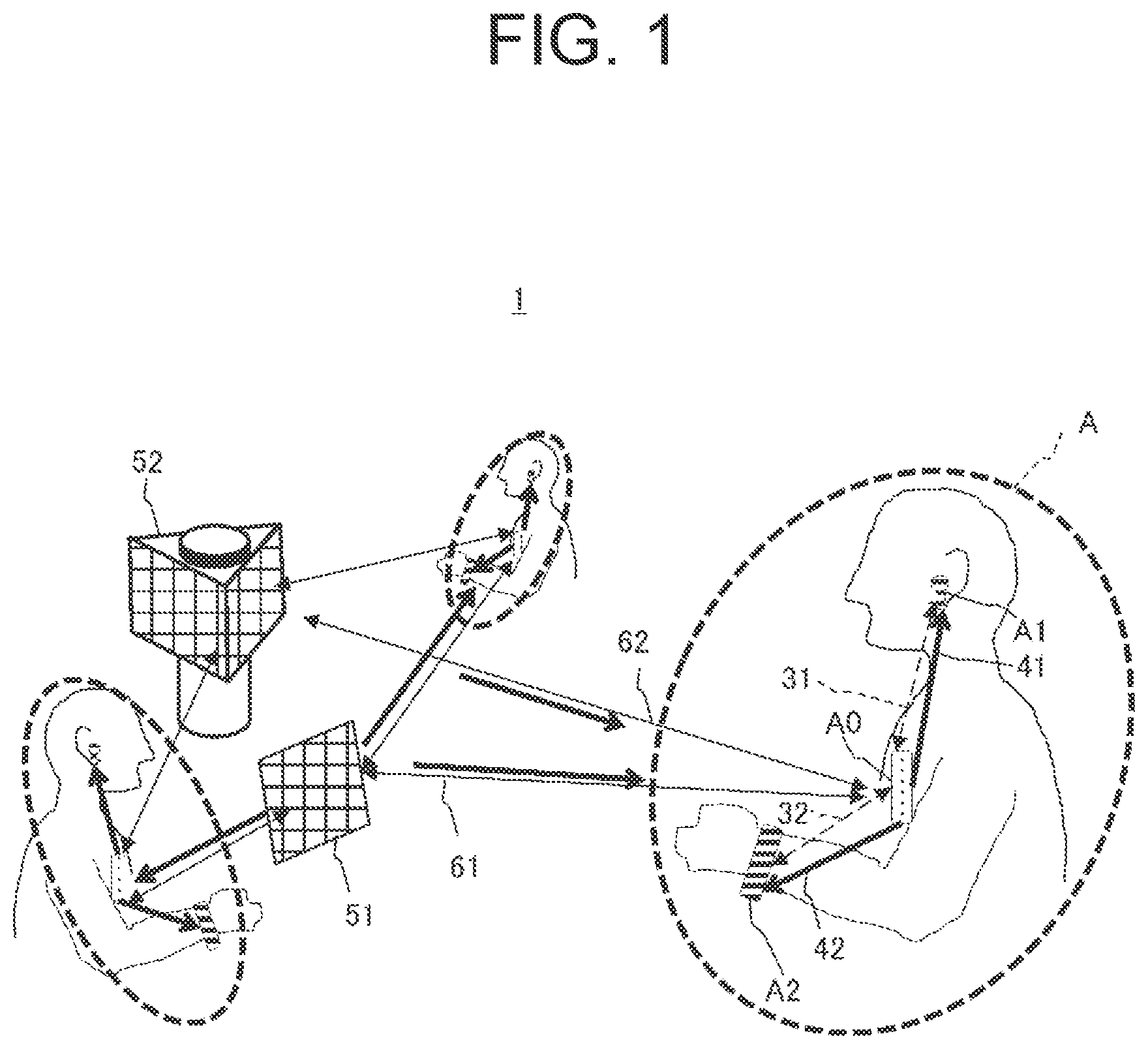
illustrates an outline of a wireless power transfer system.
is a functional block diagram of a main portable device (A 0 ).
is a schematic configuration diagram of a subordinate portable device (A 1 ).
illustrates a flowchart of processing in A 1 from a power transfer request process to a charging process.
illustrates a flowchart of processing in A 0 from a power transfer request process to a power transfer process.
illustrates a sequence of processing from power transfer request to charging process from A 1 to A 0 .
illustrates a sequence of transferring a transferrable amount of power.
illustrates a flowchart of wireless power transmitter search processing executed by A 0 .
A illustrates a power transfer mode in a second embodiment.
B illustrates a power transfer mode in the second embodiment.
illustrates a sequence of processing of power transfer request and charging in the second embodiment.
illustrates a sequence of processing of power transfer request and charging in the second embodiment.
illustrates a power transfer mode according to a third embodiment.
illustrates a flowchart of processing in a subordinate portable device B 1 of a group B requesting power transfer.
illustrates a flowchart of processing in a main portable device B 0 of a group B requesting power transfer.
illustrates a flowchart of processing in a main portable device A 0 of a group A receiving a power transfer request.
illustrates a sequence of processing of power transfer request and response between groups A and B.
illustrates a flow of power in each case of inter-group wireless power transfer.
A illustrates a power transfer mode in a third embodiment.
B illustrates a power transfer mode in the third embodiment.
illustrates a power transfer mode in the third embodiment.
illustrates an outline of a power transfer relationship between each group and a wireless power transmitter in a fourth embodiment.
illustrates a sequence of power transfer in the fourth embodiment.
DESCRIPTION OF EMBODIMENTS
Hereinafter, embodiments of the present invention will be described with reference to the drawings. Throughout the drawings, the same components and processes are provided with the same reference signs, and repetitive explanation therefor will be omitted. In the following, the embodiments of a portable device and a wireless power transfer method by the portable device according to the present invention will be described.
First Embodiment
illustrates an outline of a wireless power transfer system 1 . The wireless power transfer system 1 includes a main portable device (hereinafter referred to as “A 0 ”) and at least one subordinate portable device (hereinafter referred to as “A 1 , A 2 ”) which performs inter-device communication with A 0 . In the wireless power transfer system 1 , A 0 and A 1 , A 2 form a group A of the portable devices, and A 0 transmits electromagnetic waves (wireless power transfer waves) 41 , 42 to A 1 , A 2 to transfer (supply) power to A 1 , A 2 .
For example, A 0 is a smart phone or a tablet terminal, A 1 is a wireless earphone, and A 2 is a smart watch. The subordinate portable device may be a wearable device such as a smart glass. Any type of device may be used as the subordinate portable device as long as it operates by receiving a control signal from A 0 serving as a master by inter-device communication 31 , 32 .
As a communication method of the inter-device communication 31 , 32 , for example, Bluetooth (registered trademark) may be used. Furthermore, whether A 0 and A 1 , A 2 are in a group relationship may be determined based on whether pairing between A 0 and each of A 1 and A 2 is found through Bluetooth (registered trademark).
An exclusive wireless power transmitter 51 is capable of supplying power by wireless power transfer. A wireless base station 52 is a base station for a mobile communication system, for example, the fifth-generation mobile communication system (5G). The mobile communication system can supply power by wireless power transfer, which is equivalent to the wireless power transfer by the exclusive wireless power transmitter 51 . In addition from the exclusive wireless power transmitter 51 , A 0 receives electromagnetic waves 61 , 62 from at least one power transfer device, such as the wireless base station 52 so as to be supplied with power. Alternatively, A 0 may be charged by receiving power from an AC adapter 115 (see ).
In the group A, A 0 performs control within the group A. The group A has a star structure in which A 1 and A 2 communicate with each other through A 0 .
is a functional block diagram of A 0 . A 0 includes a first communication unit 101 , a second communication unit 102 , and a third communication unit 103 which is an inter-device communication transceiver. A 0 further includes a ROM 105 a, a RAM 105 b, a sensor 106 , a camera 107 , a microphone 108 , a speaker 109 , a display 110 , an LED 111 , a power reception control circuit 112 , and a power transfer control circuit 113 , each of which is connected to a controller 104 .
Each of the first communication unit 101 , the second communication unit 102 , and the third communication unit 103 includes, a first antenna 101 a, a second antenna 102 a, and a third antenna 103 a, respectively, a first antenna switch (SW) 101 b, a second antenna SW 102 b, and a third antenna SW 103 b, respectively, and a first wireless IC 101 c, a second wireless IC 102 c, and a third wireless IC 103 c, respectively.
The first communication unit 101 is used for wireless communication in a millimeter wave band. The second communication unit 102 is used for wireless communication in a microwave band. The third communication unit 103 is used for wireless communication in the microwave band or wireless communication in the millimeter wave band. Among the various types of wireless communication, the first communication unit 101 and the second communication unit 102 perform wireless communication with a base station of a mobile communication system such as the fifth-generation mobile communication system (5G). Therefore, the exclusive wireless power transmitter 51 corresponds to a mobile communication system communication transceiver. Furthermore, the first communication unit 101 and the second communication unit 102 receive or transfer power by using electromagnetic waves when each of the antenna switches therein is switched. Therefore, the first communication unit 101 and the second communication unit 102 correspond to an external communication transceiver for receiving electromagnetic waves (wireless power transfer waves). Among the various types of wireless communication, the third communication unit 103 performs wireless communication such as Wi-Fi (registered trademark), WiGig (registered trademark), or Bluetooth (registered trademark), and a plurality of the third communication units 103 may be provided. Therefore, the third communication unit 103 functions as a wireless communication transceiver.
Three sets of hardware for the first communication unit 101 , the second communication unit 102 , and the third communication unit 103 may be used. Otherwise, a set of hardware may be shared by the second communication unit 102 and the third communication unit 103 by changing the control logics therein for their operations. In this case, A 0 includes two sets of hardware for the two communication units of the first communication unit 101 and the second communication unit 102 while using a plurality of control logics for the three communication units for their operations.
A 0 further includes a battery 114 . The power reception control circuit 112 charges the battery 114 . Furthermore, the power reception control circuit 112 receives power from the AC adapter 115 via a commercial power source.
The power transfer control circuit 113 extracts power from the battery 114 and transmits electromagnetic waves (radio waves) through the first communication unit 101 or the second communication unit 102 to supply A 1 with the power.
The controller 104 is configured by using, for example, a Central Processing Unit (CPU), and to load a control program stored in the ROM 105 a onto the RAM 105 b to execute the program, thereby realizing the following functional elements.
The controller 104 includes a communication control section 104 a, a power control section 104 b, an antenna control section 104 c, a wireless power transmitter search section 104 d, a device location information acquisition section 104 e, a device group information management section 104 f, and a control management section 104 g. The communication control section 104 a is configured to control communication with other mobile devices. The power control section 104 b is configured to control power of A 0 . The antenna control section 104 c is configured to control the first antenna SW 101 b, the second antenna SW 102 b, and the third antenna SW 103 b based on information such as communication frequency by the communication control section 104 a. The wireless power transmitter search section 104 d is configured to search for the exclusive wireless power transmitter 51 or a mobile device having a power transfer function existing therearound. The device location information acquisition section 104 e is configured to acquire location information of the exclusive wireless power transmitter 51 or the mobile device having the power supply function existing therearound and transmit the acquired location information to other portable devices. The device group information management section 104 f is configured to manage device information such as battery capacities and functions of the wireless devices in the group A to which A 0 itself belongs, as well as information at different times such as residual power amounts, location, use frequency, and other similar information relating to a wireless device which performs communication outside the group. The control management section 104 g is configured to perform overall control of the main portable device A 0 .
is a schematic configuration diagram of A 1 . A 1 is a portable device which includes a power reception function but does not include a power transfer function. In this connection, in the second embodiment and thereafter which will be described later, A 1 includes the power transfer function.
The basic configuration of A 1 is the same as that of A 0 , but differs in that A 1 does not include the power transfer control circuit 113 . Accordingly, A 1 only receives power from the exclusive wireless power transmitter 51 or A 0 existing therearound, but cannot transfer power to A 0 .
With reference to to , power transfer processing from A 0 to A 1 forming the group A when power of A 1 is insufficient will be described. illustrates a flowchart of processing in A 1 from a power transfer request process to a charging process. illustrates a flowchart of processing in A 0 from the power transfer request process to a power transfer process. illustrates a sequence of the processing from power transfer request to charging process from A 1 to A 0 .
Based on a device group information management section 204 f of a controller 204 , A 1 transmits, to A 0 that performs control within the group A, a power transfer request notification, location information of A 1 , and information of a required power amount P_A 1 (step S 401 ), and A 0 receives them (step S 501 ).
The device group information management section 104 f of A 0 stores the location information of A 1 and information of the required power amount P_A 1 in the RAM 106 b.
Next, A 0 transmits a reception notification of the power transfer request notification to A 1 (step S 502 ), and A 1 receives the notification (step S 402 ).
Then, A 0 transmits a standby command to A 1 (step S 503 ), and A 1 receives the command (step S 403 ) and is shifted into a standby state (step S 404 ).
The power control section 104 b of A 0 confirms a residual battery amount PB (step S 504 ) to determine whether wireless power transfer of the required power amount P_A 1 that has been previously requested from A 1 can be performed. In the first embodiment, the determination above is made based on whether a difference between PB and P_A 1 is greater than an amount of power required to operate A 0 (power transfer lower allowable limit value) Pth (step S 505 ).
The power transfer lower allowable limit value Pth may be an operation guarantee power amount of A 0 , or may be a value greater than the operation guarantee power amount.
When the power residual amount PB-P_A 1 of A 0 after transferring power to A 1 is higher than the power transfer lower allowable limit value Pth (step S 505 /Yes), the power control section 104 b determines that the wireless power transfer to A 1 can be performed. Then, the power control section 104 b transmits a power transfer available notification to A 1 (step S 506 ), and A 1 receives the notification (step S 405 /Yes).
Next, A 0 transmits a power transfer start notification to A 1 (step S 507 ), and A 1 receives the notification (step S 406 ).
A 0 starts transferring power (step S 508 ), and A 1 receives the power (step S 407 ).
A power control section 204 b of A 1 periodically reads a battery terminal voltage VB during power transfer (step S 408 ) to determine whether the battery terminal voltage VB exceeds a required voltage value (charge determination threshold) Vth (step S 409 ). After the battery terminal voltage VB exceeds the charge determination threshold Vth (step S 409 /Yes), the power control section 204 b determines that charging is completed (step S 410 ), and transmits a charge completion notification to A 0 (step S 411 ).
When A 0 receives the charge completion notification from A 1 (step S 509 ), A 0 terminates the power transfer to A 1 (step S 510 ) and completes the charging process (step S 412 ).
In step S 505 , when the power residual amount PB-P_A 1 of A 0 after transferring power to A 1 is equal to or less than the power transfer lower allowable limit value Pth (step S 505 /No), the processing of transferring the total amount of the requested power from A 1 cannot be performed. In this case, alternative processing including processing of transferring a transferrable amount of power or processing of searching for a wireless power transmitter (step S 521 ), which will be described below, is executed.
Processing of Transferring Transferrable Amount of Power
In the processing illustrated in to , at the stage when A 1 finishes receiving the amount of power that can be transmitted from A 0 which is a transmission source, A 1 transmits a completion notification to A 0 which is the transmission source.
On the other hand, the residual amount of the battery 114 of A 0 does not always satisfy the required power from A 1 . In such a case, as the alternative processing, only a transferrable amount of power may be transferred to A 1 .
illustrates a sequence of transferring a transferrable amount of power. As illustrated in , even when the total amount of power requested by A 1 cannot be transferred, A 0 may calculate the transferrable amount of power and then complete the charging process upon completion of the power transfer to A 1 . In this case, when the determination result in step S 505 of is negative, A 0 as the transmission source calculates the transferrable amount of power by, for example, computing a value of (battery residual amount PB—required power amount P_A 1 by A 1 ) by means of the power control section 104 b. When the value of (battery residual amount PB—required power amount P_A 1 by A 1 ) exceeds the power supply allowable lower limit value Pth, the power control section 104 b notifies A 1 of the transferrable amount of power in step S 506 , and transmits the power transfer start notification (step S 507 ). The controller 104 outputs a power transfer instruction signal to the power transfer control circuit 113 to start transferring power (step S 508 ). In the first embodiment, the power transfer lower allowable limit value Pth is an amount of power required to operate the device A 0 .
The power control section 104 b transmits the power transfer completion notification to A 1 upon completion of power transfer of the transferrable amount of power. Thereafter, A 0 completes the charging process.
Processing of Searching for Wireless Power Transmitter
In the process in which A 0 determines whether wireless power transfer to A 1 can be performed (step S 505 ), when the value of PB-P_A 1 is less than the power transfer lower allowable limit value Pth, A 0 may search for another wireless power transmitter while keeping A 1 in the standby state (step S 521 ).
illustrates a flowchart of wireless power transmitter search processing executed by A 0 .
The wireless power transmitter search section 104 d of A 0 searches for a wireless power transmitter (exclusive wireless power transmitter) that can be paired (step S 801 ). For example, the search for a wireless power transmitter is performed by wireless communication by causing the communication control section 104 a to activate an ad hoc mode of Wi-Fi (registered trademark) of the third communication unit 103 . Alternatively, the search may be performed through a mobile communication system such as the 5G system by causing the communication control section 104 a to activate the first communication unit 101 or the second communication unit 102 . When the wireless power transmitter search section 104 d can find a wireless power transmitter (step S 801 /Yes), it transmits a power transfer request to the wireless power transmitter as found (step S 802 ).
When the wireless power transmitter search section 104 d fails to find a wireless power transmitter (step S 801 /No), it transmits a power transfer request to the wireless base station (step S 807 ).
The antenna control section 104 c confirms the frequency used in wireless power transfer with the wireless base station or the wireless power transmitter, selects the first communication unit 101 or the second communication unit 102 , and sets the first antenna switch 101 b or the second antenna switch 102 b as selected to the power reception control circuit side (step S 803 ).
Upon completion of pairing with the wireless base station or the wireless power transmitter, the power control section 104 b receives electromagnetic waves from the first antenna 101 a or the second antenna 102 a, and the power reception control circuit 112 receives power. The received power is charged in the battery 114 (step S 804 ).
The power control section 104 b monitors the residual amount of the battery 114 . When determining that charging is completed (step S 805 /Yes), the power control section 104 b transmits a charge completion notification to the wireless base station or the wireless power transmitter, and terminates the power reception (step S 806 ). The power reception continues until completion of charging (step S 805 /No).
Since it is assumed that power reception via a mobile communication system such as the 5G system is subject to billing, the following processing may be performed to minimize the billing. That is, power reception is started only when the battery residual amount is equal to or less than a predetermined power reception start threshold, and it is stopped when the battery residual amount reaches a power reception stop threshold.
The power reception start threshold may be a value equal to or greater than the power transfer lower allowable limit value Pth, but should be a value smaller than the power reception stop threshold. The power reception stop threshold may be a value smaller than a charging capacity of the battery 114 , in other words, a value smaller than the fully charged value, for example, 80% of the maximum storage amount. This processing makes it possible to reduce, as much as possible, the power transfer through the 5G system which may be subject to billing.
On the other hand, since the power transfer through a wireless power transmitter is not subject to billing when, for example, the wireless power transmitter is at home, the power reception start threshold and the power reception stop threshold are not necessarily provided.
According to the first embodiment, when A 1 needs power transfer, it transmits a power transfer request to A 0 to receive power from A 0 . Since A 0 and A 1 perform inter-device communication, communication with a wireless power transmitter is not required when A 1 receives the power. As a result, the frequency band to be used in power transfer from the wireless power transmitter is not occupied.
For example, in the case where a single user owns a plurality of wearable devices such as a smartphone, wireless earphone, and smartwatch, when each device individually communicates with a 5G base station (corresponding to a mobile wireless base station) or a wireless power transmitter, a plurality of frequency bands is required for each device. With this regard, according to the first embodiment, since the portable devices owned by the single user form a group within which the wireless power transfer can be performed, thereby suppressing occupation of a plurality of finite frequency bands by the single user and facilitating wireless power transfer from the wireless power transmitter or the 5G base station to a plurality of users.
In the first embodiment, A 0 executes the wireless power transmitter search processing as a part of the processing of responding the power transfer request from the A 0 . Meanwhile, A 0 may execute the wireless power transmitter search processing in accordance with the residual amount of the battery 114 of A 0 , regardless of the presence or absence of the power transfer request.
For example, it may be configured that the power control section 104 b monitors the residual amount of the battery 114 of A 0 , and when detecting that the battery residual amount becomes equal to or less than the threshold for determining start of power reception (power reception start threshold), it executes the wireless power transmitter search processing.
As a result, for example at visiting places, the main portable device A 0 is not fully charged but supplied with a necessary and sufficient amount of power while being fully charged at home.
Second Embodiment
A second embodiment is configured to, when the battery residual amount of A 0 cannot satisfy the required power of A 1 , transfer power to A 1 by using a residual battery amount of another A 0 forming the group A.
A and B illustrate a power transfer mode in the second embodiment. and illustrate a sequence of processing of power transfer request and charging in the second embodiment.
A illustrates a mode in which A 2 wirelessly transfers power to A 0 , then A 0 determines whether power transfer from A 0 to A 1 can be performed (step S 505 , step S 506 ), and thereafter, A 0 transfers the power to A 1 .
Alternatively, as illustrated in B , A 0 may transmit, to A 2 , the location information of A 1 stored in a memory of the device group information management section 104 f of A 0 so that A 2 directly transfers power to A 1 .
Furthermore, as illustrated in , A 1 may receive, from the portable device A 2 , an amount of power which has not been satisfied by the power transfer from A 0 .
In this case, when the value of PB-P_A 1 is less than Pth in step S 505 , A 0 transmits, to the portable device A 2 in the group A, a battery residual amount confirmation request, the location information of A 1 , and information of an insufficient amount of power supplied from A 0 to A 1 .
Upon receiving them, A 2 causes the power control section 204 b to confirm the battery residual amount of A 2 and notifies A 0 with the amount as confirmed.
The power control section 104 b of A 0 calculates an amount of power that can be transmitted to A 1 from A 0 and an amount of power that can be transmitted to A 1 from A 2 , respectively, based on the battery residual amount of A 2 received from A 2 . Then, A 0 notifies A 1 with the amount of power to be transmitted from A 2 .
Thereafter, A 0 starts transferring power to A 1 , receives, from A 1 , a power transfer completion notification of the required amount of power, and then transmits, to A 2 , the power transfer completion notification received from A 1 . Upon receiving, from A 0 , the power transfer completion notification from A 0 to A 1 , A 2 starts transferring power to A 1 .
When receiving a certain amount of power, A 1 transmits a power reception completion notification to A 0 . Upon receiving the power reception completion notification from A 1 , A 0 transmits a completion notification to A 2 . When receiving the completion notification, A 2 terminates power transfer to A 1 , and then completes the power transfer to A 1 .
In the processing above, when receiving power from A 0 , A 1 transmits the completion notification to A 0 , and when receiving power from A 2 , A 1 transmits the completion notification to A 2 . That is, A 1 transmits the completion notification to each power transfer source at each stage where A 1 receives each amount of power that can be transmitted.
In , A 1 transmits the power reception completion notification to A 0 and A 0 transmits the power transfer completion notification to A 2 . Meanwhile, as illustrated in , A 0 may notify A 1 of completion of power transfer and transmit the power transfer completion notification to A 2 .
In the processing above, the power transfer to A 1 from A 2 follows the power transfer to A 1 from A 0 . Meanwhile, the order of power transfer may be reversed. In addition, A 0 and A 2 may transfer power to A 1 at the same time.
The second embodiment is applied to the case where the communication network in the group A has a star structure whose center is A 0 . Meanwhile, the second embodiment may be also applicable to the cases where the communication network in the group A has a mesh structure, a full-connect structure, and the like.
As described above, according to the second embodiment, a portable device can be supplied with power from not only a wireless power transmitter for exclusive use of wireless transmission but also another portable device. As a result, the load of the exclusive wireless power transmitter is distributed to the portable device capable of transferring power, thereby making it possible to reduce the load of the exclusive wireless power transmitter.
Third Embodiment
A third embodiment is configured to transfer power between a plurality of groups of portable devices. illustrates a power transfer mode according to the third embodiment.
illustrates, for convenience of explanation, communication and power transfer between two groups, the group A and a group B. The configuration of the group B is the same as that of the group A described above. The communication network in each group A, B has a star structure each of which the center is A 0 and B 0 , respectively.
When a subordinate portable device (hereinafter, referred to as “B 1 ”) controlled by a main portable device (hereinafter, referred to as “B 0 ”) makes a power transfer request among the portable devices forming the group B, if there is no power margin in the group B, the subordinate portable device has to make the request to the outside of the group B.
illustrates a flowchart of processing in the subordinate portable device B 1 of the group B making a power transfer request. illustrates a flowchart of processing in the main portable device B 0 of the group B making the power transfer request. illustrates a flowchart of processing in the main portable device A 0 of the group A receiving the power transfer request. illustrates a sequence of the processing of power transfer request and response between the groups A, B.
Firstly, B 1 transmits a power transfer request to B 0 by inter-device communication (step S 1301 ), and B 0 receives the request (step S 1401 ). Since steps S 1402 to S 1421 are the same as those of the first embodiment, the explanation thereof is omitted.
Since B 0 and B 2 do not have sufficient power to be transmitted to B 1 (step S 1422 /No), the wireless power transmitter search section 104 d of B 0 searches for a wireless power transmitter in the outside of the group B based on the information in the device group information management section 104 f. At this time, for example, the search for a wireless power transmitter is performed by wireless communication 10 ab by causing the communication control section 104 a to activate an ad hoc mode of Wi-Fi (registered trademark) of the third communication unit 103 .
When A 0 that performs control within the group A is found by this search (step S 1422 /Yes), the device location information acquisition section 104 e of B 0 and the device location information acquisition section 104 e of A 0 exchange information in the respective device group information management sections 104 f, and B 0 transmits, to A 0 , the power transfer request and information of a required amount of power of B 1 (step S 1423 , step S 1501 ).
The power control section 104 b of A 0 calculates an amount of power that can be transmitted, and the device group information management section 104 f determines whether power transfer can be performed based on the location information acquired by the device location information acquisition section 104 e (step S 1502 , step S 1503 ).
When determining that the power transfer can be performed (step S 1424 /Yes), A 0 transmits, to B 0 , a power transfer available notification and information of a transferrable amount of power, and B 0 receives them (step S 1504 ).
B 0 transmits, to A 0 , the device IDs and location information of B 0 and B 1 (step S 1425 , step 1505 ) so that A 0 can recognize the relative positional relationship between them.
The device ID can be used, for example, as billing information. The device ID and location information of each device may be obtained from a base station (not illustrated) of a wireless communication network of portable devices. Based on the information above, A 0 transmits a power transfer approval request notification to B 0 (step S 1506 ), and B 0 receives the notification (step S 1426 ).
B 0 transmits, to B 1 , a power transfer approval notification received from A 0 (step S 1427 ), and B 1 receives the notification (step 1306 ).
B 0 transmits a power transfer start acceptance notification to A 0 (step S 1428 ), and A 0 receives the notification (step S 1507 ). Upon receiving the power transfer start acceptance notification, A 0 starts transferring power to B 1 (step S 1307 , step S 1508 ).
B 1 reads a battery terminal voltage VB and keeps receiving power until VB exceeds a voltage value required to operate B 1 (charge determination threshold) Vth (step S 1308 , step S 1309 ). When VB exceeds Vth (step S 1309 /Yes), B 1 completes charging (step S 1310 ) and transmits a charge completion notification to B 0 (step S 1311 ), and B 0 receives the notification (step S 1429 ). Upon receiving the charge completion notification from B 1 , B 0 transmits a notification that B 1 completes charging to A 0 (step S 1430 ), and A 0 receives the notification (step S 1509 ) and terminates the power transfer (step S 1510 ).
In the wireless power transmitter search processing performed by B 0 , B 0 accesses A 0 that performs control within the group A (step S 1423 ), and A 0 determines whether power transfer can be performed based on the information of the transferrable amount of power of A 0 (step S 1503 ). Meanwhile, a determination method is not limited thereto, and A 0 may make determination above based on the total transferrable amount of power that can be transmitted from A 1 and A 2 which are portable devices capable of transferring power other than A 0 in the group A.
In the processing above, at the stage when B 1 receives the amount of power that can be transmitted from A 0 , B 1 transmits a completion notification to the transmission source. In view of the power condition of the transmission source, A 0 may stop transferring power to B 1 at the time when power transfer of the transferrable amount of power calculated by A 0 as the transmission source is finished.
illustrates a flow of power in each case of inter-group wireless power transfer. The case described with reference to to 16 corresponds to Case 2-1 in .
Case 1, Case 3, and Case 3-1 are cases where B 0 makes a power transfer request while Case 2, Case 2-1, Case 4, Case 4-1, Case 4-2 and Case 4-3 are cases where B 1 makes a power transfer request.
Furthermore, a portable device to be supplied with power is A 0 in Case 1, Case 2, and Case 2-1 while it is A 1 in other cases. When a communication network has a star structure, A 1 and B 1 always need to go through A 0 and B 0 to communicate with the outside of the group. On the other hand, the flow of power does not necessarily pass through A 0 and B 0 that perform control within the groups. Since the power transfer efficiency decreases as the number of portable devices interposed therebetween increases, direct power transfer, such as A 1 =B 1 in Case 4-1, is the most efficient power transfer when comparing Case 4, Case 4-1, Case 4-2, and Case 4-3.
Furthermore, in the case where the wireless power transmitter search section 104 d of the controller 104 of B 0 searches the outside of the group to find a wireless power transmitter based on the information in the device group information management section 104 f, the wireless power transmitter to be found may be an exclusive wireless power transmitter 1800 for exclusive use of wireless transmission which exists outside the group B as illustrated in A . In this case, it may be configured that B 0 that performs control within the group B may communicate with the exclusive wireless power transmitter 1800 for exclusive use of wireless transmission by the communication 1801 bs, receive the power transfer 1802 bs, and transfer the power to the subordinate portable device A 1 in the group A through A 0 .
Furthermore, as illustrated in B , it may be configured that B 0 transmit the location information and information of a required power amount of B 1 to the exclusive wireless power transmitter 1800 by the communication 1801 bs so that B 1 receives the information relating to power transfer to be performed by the exclusive wireless power transmitter 1800 through A 0 . As a result, the exclusive wireless power transmitter 1800 can directly transmit power to B 1 .
Still further, when the power control section 104 b, the device location information acquisition section 104 e, and the device group information management section 104 f of the controller 104 of B 0 determine that the required power amount of B 1 cannot be fully satisfied by power transfer from the group A (for example, 20% or less of the required power amount), B 0 searches for a wireless power transmitter in a group other than the group A. For example, as illustrated in , B 0 may access a portable device C 0 that performs control within a group C so that the portable device C 1 belonging to the group C transfers power to B 1 . The search for a wireless power transmitter may be performed via a base station (not illustrated) of a wireless communication network of portable devices.
As described above, according to the third embodiment, a portable device can be supplied with power not only from a wireless power transmitter for exclusive use of wireless transmission, but also from other portable devices. As a result, the load of the exclusive wireless power transmitter is distributed to the portable device capable of transferring power, thereby making it possible to reduce the load of the exclusive wireless power transmitter.
Fourth Embodiment
A fourth embodiment is configured to transfer power between a plurality of groups while the groups are receiving power from a wireless power transmitter for exclusive use of wireless transmission. illustrates an outline of a power transfer relationship between each group and a wireless power transmitter in the fourth embodiment. illustrates a sequence of power transfer in the fourth embodiment.
illustrates the groups A, B, C of the portable devices and the exclusive wireless power transmitter 1800 for exclusive use of wireless transmission. The groups A, C are positioned opposite to the group B across the exclusive wireless power transmitter 1800 .
It is assumed that the exclusive wireless power transmitter 1800 transfers power to A 0 of the group A at the frequency of fA while transferring power to the main portable device B 0 of the group B at the frequency of fB. In this state, as illustrated in , C 1 transmits a power transfer request to C 0 by using inter-device communication 10 c.
Upon receiving the power transfer request from C 1 , C 0 transmits, to C 1 , a power transfer request reception notification and then a standby command by using the inter-device communication 10 c. The wireless power transmitter search section 104 d of C 0 searches the outside of its group to find a wireless power transmitter based on the information in the device group information management section 104 f. At this time, for example, the search for a wireless power transmitter is performed by causing the communication control section 104 a to activate an ad hoc mode of Wi-Fi (registered trademark) of the third communication unit 103 to find the exclusive wireless power transmitter 1800 existing nearby.
C 0 and the exclusive wireless power transmitter 1800 mutually exchange information stored in the device group information management section via wireless communication 10 cs.
C 0 makes a power transfer request to the exclusive wireless power transmitter 1800 . However, since the exclusive wireless power transmitter 1800 has already been transferring power to A 0 and B 0 at the frequency of fA and fB, respectively, it returns rejection of power transfer to C 0 .
Next, the wireless power transmitter search section 104 d of the controller 104 of C 0 finds A 0 and B 0 based on the information in the device group information management section 104 f. Between C 0 and A 0 and between C 0 and B 0 , the device location information acquisition section 104 e included in each of A 0 , B 0 , and C 0 exchanges the information in the device group information management section 104 f included in each of A 0 , B 0 , and C 0 by using the wireless communication 10 ca and 10 b. At the same time, C 0 transmits a power transfer request and information of a required amount of power to each of A 0 and B 0 .
Each of A 0 and B 0 calculates an amount of power that can be transmitted by means of the power control section 104 b, the device location information acquisition section 104 e, and the device group information management section 104 f of each control device 104 , and determines the frequency that can be used so as to determine whether power transfer can be performed. When determining that power transfer can be performed, each of A 0 and B 0 transmits a power transfer available notification, information of a transferrable power amount, and power transfer frequency to each portable device that performs control within each of other groups and the exclusive wireless power transmitter 1800 .
The groups A, C are located on the opposite side of the group B with the exclusive wireless power transmitter 1800 interposed therebetween. Accordingly, when the frequency of fB used in the power transfer 1802 bs from the exclusive wireless power transmitter 1800 to B 0 is used for the power transfer 1802 ca from A 0 to C 1 , the power transfer 1802 ca does not interfere with the power transfer 1802 bs nor the power transfer 1802 as (frequency fA) from the exclusive wireless power transmitter 1800 to A 0 . As a result, it is possible to increase the efficiency of frequency use in the area where the groups A, B, C of portable devices and the exclusive wireless power transmitter 1800 for exclusive use of wireless transmission exist.
In order to simplify the explanation, illustrates only the data transmitted from A 0 . Upon receiving the above, C 0 transmits, to A 0 , the device IDs and location information of C 0 and C 1 , thereby making it possible to recognize the relative positional relationship between them and allowing the device IDs to be used as billing information. The device IDs and device location information may be obtained from a base station (not illustrated) of a wireless communication network of portable devices. Based on the information above, A 0 transmits a power transfer approval request notification to C 0 , and C 0 transmits a power transfer approval notification of A 0 to C 1 while transmitting a power transfer start acceptance notification to A 0 . Upon receiving the power transfer start acceptance notification, A 0 switches the antenna for the frequency band of fB to the power transfer control circuit 113 side by the first antenna switch 101 b or the second antenna switch 102 b. Furthermore, C 1 switches the antenna for the frequency band of fB to the power reception control circuit 112 side by the first antenna switch 101 b or the second antenna switch 102 b. Thereafter, A 0 starts transferring power to C 1 .
At the stage when A 0 , which is the transmission source, finishes transferring power of the calculated transferrable amount, A 0 stops transferring power to C 1 and transmits a power transfer completion notification to C 0 . Each of A 0 and C 1 switches the antenna switch for the frequency band of fB to the first wireless IC 101 c side or the second wireless IC 102 c side.
In the above, the case where the frequency interference does not occur during the inter-group power transfer has been described. On the other hand, in the case where the frequency interference occurs during the inter-group power transfer, control which is different from the above-described control may be performed. For example, the power control section 104 b, the device location information acquisition section 104 e, and the device group information management section 104 f of the A 0 calculate an amount of power that can be transmitted, determine the frequency that can be used, and transmit a power transfer available notification, and information of the transferable power amount and power transfer frequency to a portable device that performs control within each of other groups and the exclusive wireless power transmitter 1800 . At this point, the residual amount of power transfer from the exclusive wireless power transmitter 1800 to B 0 is compared with the amount of power transfer from A 0 to C 1 . As a result of the comparison above, when the residual amount of power transfer from the exclusive wireless power transmitter 1800 to B 0 is greater than the amount of power transfer from A 0 to C 1 (for example, 30% or more), control may be performed so as to cause B 0 to pass the frequency of fB to the power transfer to C 1 . According to the control above, it is possible to secure the frequency for performing wireless power transfer to a portable device or a subordinate portable device which requires high necessity of charging.
According to the fourth embodiment, a portable device can be supplied with power not only from a wireless power transmitter for exclusive use of wireless transmission, but also from other portable devices. As a result, the load of the exclusive wireless power transmitter 1800 is distributed to the portable device capable of transferring power, thereby making it possible to reduce the load of the exclusive wireless power transmitter 1800 . Furthermore, by using the positional relationship between the groups, it is possible to increase the efficiency of frequency use in the area where a plurality of groups exists.
The present invention should not be interpreted as being limited to the embodiments described above. Modifications of the specific configurations without departing from the idea and concept of the present invention are included in the technical scope of the present invention.
For example, in the embodiments above, only three portable devices are illustrated per group in order to simplify the explanation. Meanwhile, the number of portable devices per group is not limited to three. Generally, a group X is formed by a portable device X 0 that performs control within the group X and a portable device Xi (i=1, 2, . . . ) that operates in accordance with the portable device X 0 , and a network in the group X has a star structure whose center is X 0 . Meanwhile, the group X may be formed by the portable device X 0 alone. The portable device X 0 that performs control within the group X may be determined by the user by using, for example, a pairing function of Bluetooth (registered trademark), or may be determined based on information such as a battery capacity, location information, residual power amount, power reception function, power transfer function, power transfer efficiency, and power reception efficiency, in addition to IDs of devices, by communicating between the portable devices existing nearby. For example, the portable device X 0 that performs control within the group X may be determined to be a portable device having the power transfer function, power reception function, wireless means of various types of communication standard, and large battery capacity.
REFERENCE SIGNS LIST
• 1 : wireless power transfer system • 31 : inter-device communication • 32 : inter-device communication • 41 : electromagnetic waves • 42 : electromagnetic waves • 51 : wireless power transmitter • 52 : 5G base station • 61 : electromagnetic waves • 62 : electromagnetic waves • A 0 : portable device • A 1 : subordinate portable device • A 2 : portable device
Figures (20)
Citations
This patent cites (11)
- US20100315045
- US20130026981
- US20160197488
- US2010-104103
- US2010-237931
- US2015-061384
- US2015-204708
- US2016-512677
- US2017-139954
- US2018-137921
- US2014/121296