Abstract
The present invention discloses a camera optical lens with seven-piece lens including, from an object side to an image side in sequence, a first lens having a positive refractive power, a second lens having a negative refractive power, a third lens having a positive refractive power, a fourth lens having a negative refractive power, a fifth lens having a negative refractive power, a sixth lens having a positive refractive power and a seventh lens having a negative refractive power. The camera optical lens satisfies the following conditions: 0.30≤R7/R5≤1.50 and −3.00≤R13/R14≤−1.00. The camera optical lens according to the present invention has excellent optical characteristics, such as large aperture, wide-angle, and ultra-thin.
Claims (19)
1. A camera optical lens with seven-piece lenses, comprising, from an object side to an image side in sequence: a first lens having a positive refractive power, a second lens having a negative refractive power, a third lens having a positive refractive power, a fourth lens having a negative refractive power, a fifth lens having a negative refractive power, a sixth lens having a positive refractive power and a seventh lens having a negative refractive power; wherein the camera optical lens satisfies the following conditions:
Show 18 dependent claims
2. The camera optical lens according to claim 1 , wherein, the first lens has an object side surface being convex in a paraxial region and an image side surface being concave in the paraxial region; the camera optical lens further satisfies the following conditions:
3. The camera optical lens according to claim 2 further satisfying the following conditions:
4. The camera optical lens according to claim 1 , wherein, the second lens has an object side surface being convex in a paraxial region and an image side surface being concave in the paraxial region; the camera optical lens further satisfies the following conditions:
5. The camera optical lens according to claim 4 further satisfying the following conditions:
6. The camera optical lens according to claim 1 further satisfies the following conditions:
7. The camera optical lens according to claim 6 further satisfying the following conditions:
8. The camera optical lens according to claim 1 , wherein, the fourth lens has an image side surface being concave in a paraxial region; the camera optical lens further satisfies the following conditions:
9. The camera optical lens according to claim 8 further satisfying the following conditions:
10. The camera optical lens according to claim 1 , wherein, the fifth lens has an object side surface being concave in a paraxial region and an image side surface being convex in the paraxial region.
11. The camera optical lens according to claim 1 , wherein, the sixth lens has an object side surface being convex in a paraxial region and an image side surface being concave in the paraxial region; the camera optical lens further satisfies the following conditions:
12. The camera optical lens according to claim 11 further satisfying the following conditions:
13. The camera optical lens according to claim 1 , wherein, the object side surface of the seventh lens is concave in a paraxial region and the image side surface of the seventh lens is concave in the paraxial region; the camera optical lens further satisfies the following conditions:
14. The camera optical lens according to claim 13 further satisfying the following conditions:
15. The camera optical lens according to claim 1 , wherein an FNO of the camera optical lens is less than or equal to 1.75; where, FNO: an F number of the camera optical lens.
16. The camera optical lens according to claim 1 , wherein an FOV of the camera optical lens is greater than or equal to 77.66°; where, FOV: a field of view of the camera optical lens in a diagonal direction.
17. The camera optical lens according to claim 1 further satisfying the following conditions: TTL/IH≤1.56; where, IH: an image height of the camera optical lens; and TTL: a total optical length from an object side surface of the first lens of the camera optical lens to an image surface of the camera optical lens along an optical axis.
18. The camera optical lens according to claim 1 further satisfying the following conditions: 0.59≤f12/f≤2.07; where, f: a focal length of the optical camera lens; and f12: a combined focal length of the first lens and the second lens.
19. The camera optical lens according to claim 18 further satisfying the following conditions: 0.95≤f12/f≤1.66.
Full Description
Show full text →
FIELD OF THE PRESENT INVENTION
The present invention relates to an optical lens, and more particularly, to a camera optical lens suitable for handheld terminal devices, such as smart phones and digital cameras, and imaging devices, such as monitors or PC lenses.
DESCRIPTION OF RELATED ART
In recent years, with the rise of various smart devices, the demand for miniaturized camera optics has been increasing, and the pixel size of photosensitive devices has shrunk, coupled with the development trend of electronic products with good functions, thin and portable appearance, Therefore, miniaturized imaging optical lenses with an excellent image quality have become the mainstream in the current market. In order to obtain better imaging quality, a multi-piece lens structure is often used. Moreover, with the development of technology and the increase of diversified needs of users, as the pixel area of the photosensitive device continues to shrink and the system's requirements for image quality continue to increase, the seven-element lens structure gradually appears in the lens design. There is an urgent need for a wide-angle camera optical lens with excellent optical characteristics, small size, and fully corrected aberrations.
SUMMARY
In the present invention, a cameral optical lens has excellent optical characteristics with large aperture stop, ultra-thin characteristic and wide-angle.
According to one aspect of the present invention, a camera optical lens with seven-piece lens includes, from an object side to an image side in sequence, a first lens having a positive refractive power, a second lens having a negative refractive power, a third lens having a positive refractive power, a fourth lens having a negative refractive power, a fifth lens having a negative refractive power, a sixth lens having a positive refractive power and a seventh lens having a negative refractive power. Herein the camera optical lens satisfies the following conditions: 0.30≤R7/R5≤1.50 and −3.00≤R13/R14≤−1.00. R5 denotes a central curvature radius of an object side surface of the third lens, R7 denotes a central curvature radius of an object side surface of the fourth lens, R13 denotes a central curvature radius of an object side surface of the seventh lens, and R14 denotes a central curvature radius of an image side surface of the seventh lens.
Further, the first lens has an object side surface being convex in a paraxial region and an image side surface being concave in the paraxial region. The camera optical lens further satisfies the following conditions: 0.48≤f1/f≤1.52, −3.30 (R1+R2)/(R1−R2)≤−0.95, and 0.07≤d1/TTL≤0.22. f denotes a focal length of the optical camera lens, f1 denotes a focal length of the first lens, R1 denotes a central curvature radius of the object side surface of the first lens, R2 denotes a central curvature radius of the image side surface of the first lens, d1 denotes an on-axis thickness of the first lens, and TTL denotes a total optical length from the object side surface of the first lens of the camera optical lens to an image surface of the camera optical lens along an optical axis.
The camera optical lens further satisfies the following conditions: 0.77≤f1/f≤1.21, −2.06 (R1+R2)/(R1−R2)≤−1.19, and 0.11≤d1/TTL≤0.18.
Further, the second lens has an object side surface being convex in a paraxial region and an image side surface being concave in the paraxial region. The camera optical lens further satisfies the following conditions: −7.78≤f2/f≤−1.89, 1.81≤(R3+R4)/(R3−R4)≤6.38, and 0.02≤d3/TTL≤0.06. f denotes a focal length of the optical camera lens, f2 denotes a focal length of the second lens, R3 denotes a central curvature radius of the object side surface of the second lens, R4 denotes a central curvature radius of the image side surface of the second lens, d3 denotes an on-axis thickness of the second lens, and TTL denotes a total optical length from an object side surface of the first lens of the camera optical lens to an image surface of the camera optical lens along an optical axis.
The camera optical lens further satisfies the following conditions: −4.86≤f2/f≤−2.37, 2.89≤(R3+R4)/(R3−R4)≤5.11, and 0.03≤d3/TTL≤0.05.
The camera optical lens further satisfies the following conditions: 3.65≤f3/f≤201.35, −23.31≤(R5+R6)/(R5−R6)≤29.49, and 0.03≤d5/TTL≤0.11. f denotes a focal length of the optical camera lens, f3 denotes a focal length of the third lens, R6 denotes a central curvature radius of an image side surface of the third lens, d5 denotes an on-axis thickness of the third lens, and TTL denotes a total optical length from an object side surface of the first lens of the camera optical lens to an image surface of the camera optical lens along an optical axis.
The camera optical lens further satisfies the following conditions: 5.84≤f3/f≤161.08, −14.57≤(R5+R6)/(R5−R6)≤23.59, and 0.04≤d5/TTL≤0.09.
Further, the fourth lens has an image side surface being concave in a paraxial region. The camera optical lens further satisfies the following conditions: −17.16≤f4/f≤−3.27, −1.91≤(R7+R8)/(R7−R8)≤8.52, and 0.03≤d7/TTL≤0.09. f denotes a focal length of the optical camera lens, f4 denotes a focal length of the fourth lens, R8 denotes a central curvature radius of the image side surface of the fourth lens, d7 denotes an on-axis thickness of the fourth lens, and TTL denotes a total optical length from an object side surface of the first lens of the camera optical lens to an image surface of the camera optical lens along an optical axis.
The camera optical lens further satisfies the following conditions: −10.72≤f4/f≤−4.09, −1.19≤(R7+R8)/(R7−R8)≤6.82, and 0.04≤d7/TTL≤0.07.
Further, the fifth lens has an object side surface being concave in a paraxial region and an image side surface being convex in the paraxial region. The camera optical lens further satisfies the following conditions: −84.76≤f5/f≤−1.20, −46.40≤(R9+R10)/(R9−R10)≤2.23, and 0.04≤d9/TTL≤0.15. f denotes a focal length of the optical camera lens, f5 denotes a focal length of the fifth lens, R9 denotes a central curvature radius of the object side surface of the fifth lens, R10 denotes a central curvature radius of the image side surface of the fifth lens, d9 denotes an on-axis thickness of the fifth lens, and TTL denotes a total optical length from an object side surface of the first lens of the camera optical lens to an image surface of the camera optical lens along an optical axis.
The camera optical lens further satisfies the following conditions: −52.97≤f5/f≤−1.50, −29.00≤(R9+R10)/(R9−R10)≤1.78, and 0.06≤d9/TTL≤0.12.
Further, the sixth lens has an object side surface being convex in a paraxial region and an image side surface being concave in the paraxial region. The camera optical lens further satisfies the following conditions: 0.29≤f6/f≤1.65, −4.56≤(R11+R12)/(R11−R12)≤−0.34, and 0.05≤d11/TTL≤0.16. f denotes a focal length of the optical camera lens, f6 denotes a focal length of the sixth lens, R11 denotes a central curvature radius of the object side surface of the sixth lens, R12 denotes a central curvature radius of the image side surface of the sixth lens, d11 denotes an on-axis thickness of the sixth lens, and TTL denotes a total optical length from an object side surface of the first lens of the camera optical lens to an image surface of the camera optical lens along an optical axis.
The camera optical lens further satisfies the following conditions: 0.46≤f6/f≤1.32, −2.85≤(R11+R12)/(R11−R12)≤−0.42, and 0.07≤d11/TTL≤0.12.
Further, the object side surface of the seventh lens is concave in a paraxial region and the image side surface of the seventh lens is concave in the paraxial region. The camera optical lens further satisfies the following conditions: −1.93≤f7/f≤−0.40, 0.00≤(R13+R14)/(R13−R14)≤0.75, and 0.04≤d13/TTL≤0.14. f denotes a focal length of the optical camera lens, f7 denotes a focal length of the seventh lens, d13 denotes an on-axis thickness of the seventh lens, and TTL denotes a total optical length from an object side surface of the first lens of the camera optical lens to an image surface of the camera optical lens along an optical axis.
The camera optical lens further satisfies the following conditions: −1.21≤f7/f≤−0.51, 0.00≤(R13+R14)/(R13−R14)≤0.60, and 0.06≤d13/TTL≤0.11.
Further, an FNO of the camera optical lens is less than or equal to 1.75. FNO denotes an F number of the camera optical lens.
Further, an FOV of the camera optical lens is greater than or equal to 77.66°. FOV denotes a field of view of the camera optical lens.
The camera optical lens further satisfies the following conditions: TTL/IH≤1.56. IH denotes an image height of the camera optical lens, and TTL denotes a total optical length from an object side surface of the first lens of the camera optical lens to an image surface of the camera optical lens along an optical axis.
The camera optical lens further satisfies the following conditions: 0.59≤f12/f≤2.07. f denotes a focal length of the optical camera lens, and f12 denotes a combined focal length of the first lens and the second lens.
The camera optical lens further satisfies the following conditions: 0.95≤f12/f≤1.66.
BRIEF DESCRIPTION OF THE DRAWINGS
In order to explain the technical solutions in the embodiments of the present invention more clearly, the following will briefly introduce the drawings that need to be used in the description of the embodiments. Obviously, the drawings in the following description are only some embodiments of the present invention. For those of ordinary skill in the art, without creative work, other drawings can be obtained based on these drawings, among which:
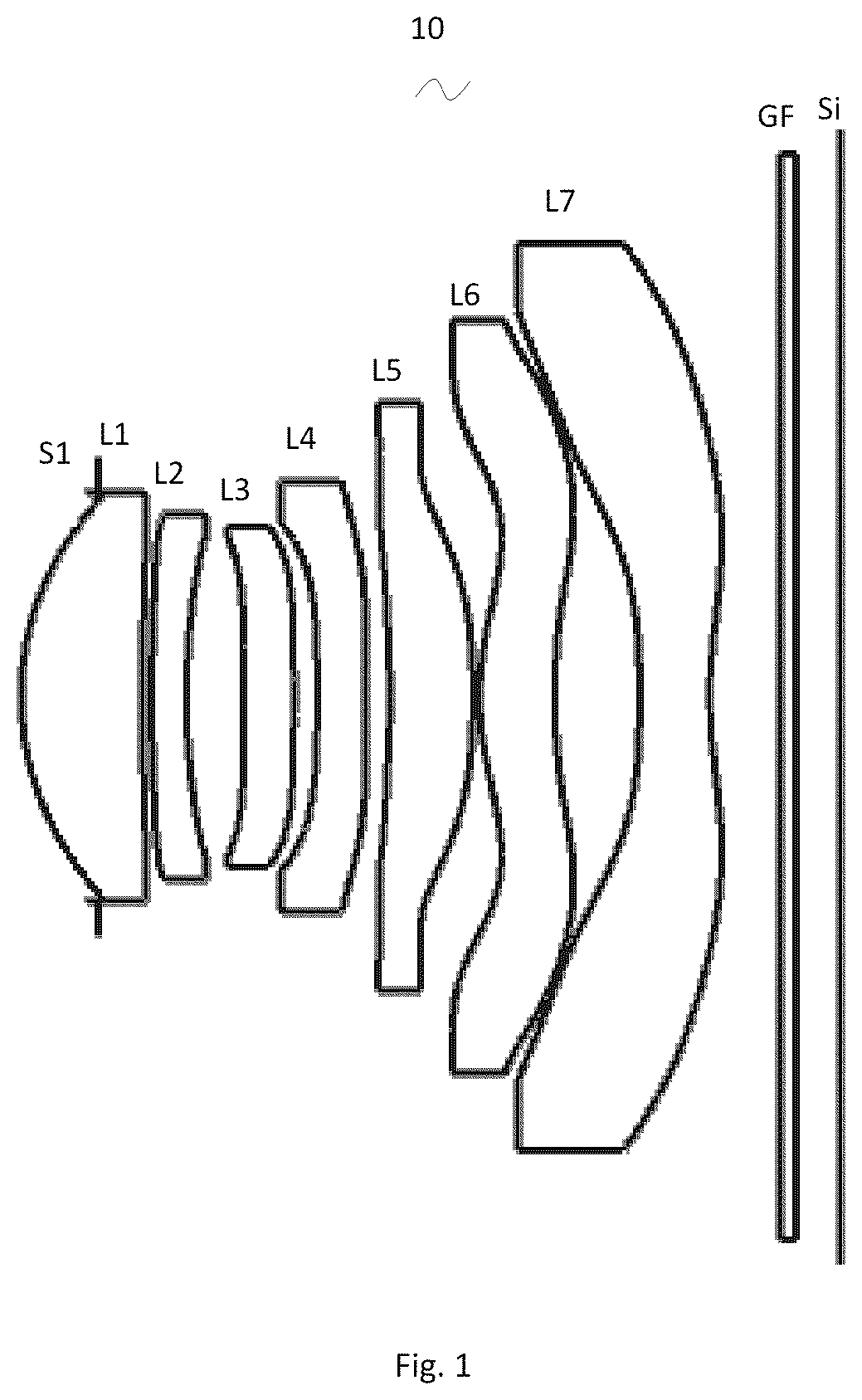
is a schematic diagram of a structure of a camera optical lens in accordance with Embodiment 1 of the present invention;
is a schematic diagram of a longitudinal aberration of the camera optical lens shown in ;
is a schematic diagram of a lateral color of the camera optical lens shown in ;
is a schematic diagram of a field curvature and a distortion of the camera optical lens shown in ;
is a schematic diagram of a structure of a camera optical lens in accordance with Embodiment 2 of the present invention;
is a schematic diagram of a longitudinal aberration of the camera optical lens shown in ;
is a schematic diagram of a lateral color of the camera optical lens shown in ;
is a schematic diagram of a field curvature and a distortion of the camera optical lens shown in ;
is a schematic diagram of a structure of a camera optical lens in accordance with Embodiment 3 of the present invention;
is a schematic diagram of a longitudinal aberration of the camera optical lens shown in ;
is a schematic diagram of a lateral color of the camera optical lens shown in ; and
is a schematic diagram of a field curvature and a distortion of the camera optical lens shown in .
DETAILED DESCRIPTION OF THE EXEMPLARY EMBODIMENTS
In order to make the objects, technical solutions, and advantages of the present invention more apparent, the embodiments of the present invention will be described in detail below. However, it will be apparent to the one skilled in the art that, in the various embodiments of the present invention, a number of technical details are presented in order to provide the reader with a better understanding of the invention. However, the technical solutions claimed in the present invention can be implemented without these technical details and various changes and modifications based on the following embodiments.
Embodiment 1
As referring to the accompanying drawings, the present invention provides a camera optical lens 10 . is the camera optical lens 10 according to embodiment 1 of the present invention. The camera optical lens 10 comprises seven-piece lenses. Specifically, from an object side to an image side, the camera optical lens 10 comprises in sequence: an aperture S 1 , a first lens L 1 , a second lens L 2 , a third lens L 3 , a fourth lens L 4 , a fifth lens L 5 , a sixth lens L 6 and a seventh lens L 7 . Optical elements like optical filter GF can be arranged between the seventh lens L 7 and an image surface Si.
The first lens L 1 is made of plastic material, the second lens L 2 is made of plastic material, the third lens L 3 is made of plastic material, the fourth lens L 4 is made of plastic material, the fifth lens L 5 is made of plastic material, the sixth lens L 6 is made of plastic material, and the seventh lens L 7 is made of plastic material. In other optional embodiments, each lens may also be made of other materials.
In the present embodiment, a central curvature radius of an object side surface of the third lens L 3 is defined as R5, and a central curvature radius of an object side surface of the fourth lens L 4 is defined as R7. The camera optical lens 10 further satisfies the following condition: 0.30≤R7/R5≤1.50. By appropriately configuring the central curvature radius R5 of the object side surface of the third lens L 3 and the central curvature radius R7 of the object side surface of the fourth lens L 4 , an aberration of the optical system is corrected, thereby improving an imaging quality.
In the present embodiment, a central curvature radius of an object side surface of the seventh lens L 7 is defined as R13, and a central curvature radius of an image side surface of the seventh lens L 7 is defined as R14. The camera optical lens 10 further satisfies the following condition: −3.00≤R13/R14≤−1.00, which specifies a shape of the seventh lens L 7 . Within this range, as the development of ultra-thin and wide-angle lens, it benefits for solving the problems, such as correcting an off-axis aberration.
In the present embodiment, an object side surface of the first lens L 1 is convex in a paraxial region, an image side surface of the first lens L 1 is concave in the paraxial region, and the first lens L 1 has a positive refractive power. In other optional embodiments, the object side surface and the image side surface of the first lens L 1 can also be set to other concave and convex distribution situations.
A focal length of the camera optical lens 10 is defined as f, and a focal length of the first lens L 1 is defined as f1. The camera optical lens 10 further satisfies the following condition: 0.48≤f1/f≤1.52, which specifies a ratio of the positive refractive power of the first lens L 1 to the focal length of the camera optical lens 10 . Within this range, the first lens L 1 has an appropriate positive refractive power, which is beneficial for reducing the aberration of the camera optical lens 10 and at the same time is beneficial for the development of ultra-thin and wide-angle lenses. Further, the following condition shall be satisfied, 0.77≤f1/f≤1.21.
A central curvature radius of an object side surface of the first lens L 1 is defined as R1, and a central curvature radius of an image side surface of the first lens L 1 is defined as R2. The camera optical lens 10 further satisfies the following condition: −3.30≤(R1+R2)/(R1−R2)≤−0.95. This condition reasonably controls a shape of the first lens L 1 , so that the first lens L 1 can effectively correct a spherical aberration of the camera optical lens 10 . Further, the following condition shall be satisfied, −2.06≤(R1+R2)/(R1−R2)≤−1.19.
An on-axis thickness of the first lens L 1 is defined as d1. A total optical length from the object side surface of the first lens L 1 to the image surface Si of the camera optical lens 10 along an optical axis is defined as TTL. The camera optical lens 10 further satisfies the following condition: 0.07≤d1/TTL≤0.22. Within this range, it benefits for realizing an ultra-thin effect. Further, the following condition shall be satisfied, 0.11≤d1/TTL≤0.18.
In the present embodiment, an object side surface of the second lens L 2 is convex in the paraxial region, an image side surface of the second lens L 2 is concave in the paraxial region, and the second lens L 2 has a negative refractive power. In other optional embodiments, the object side surface and the image side surface of the second lens L 2 can also be set to other concave and convex distribution situations.
The focal length of the camera optical lens 10 is defined as f, and a focal length of the second lens L 2 is defined as f2. The camera optical lens 10 further satisfies the following condition: −7.78≤f2/f≤−1.89. It benefits for correcting the aberration of the camera optical lens 10 by controlling the positive refractive power of the second lens L 2 being within reasonable range. Further, the following condition shall be satisfied, −4.86≤f2/f≤−2.37.
The central curvature radius of the object side surface of the second lens L 2 is defined as R3, and a central curvature radius of the image side surface of the second lens L 2 is defined as R4. The camera optical lens 10 further satisfies the following condition: 1.81≤(R3+R4)/(R3−R4)≤6.38, which specifies a shape of the second lens L 2 . Within this range, as the camera optical lens 10 develops toward ultra-thin and wide-angle, it is beneficial for correcting the problem of an on-axis chromatic aberration. Further, the following condition shall be satisfied, 2.89≤(R3+R4)/(R3−R4)≤5.11.
An on-axis thickness of the second lens L 2 is defined as d3. The total optical length from the object side surface of the first lens L 1 to the image surface Si of the camera optical lens 10 along the optical axis is defined as TTL. The camera optical lens 10 further satisfies the following condition: 0.02≤d3/TTL≤0.06. Within this range, it benefits for realizing an ultra-thin effect. Further, the following condition shall be satisfied, 0.03≤d3/TTL≤0.05.
In the present embodiment, the object side surface of the third lens L 3 is concave in the paraxial region, an image side surface of the third lens L 3 is convex in the paraxial region, and the third lens L 1 has a positive refractive power. In other optional embodiments, the object side surface and the image side surface of the third lens L 3 can also be set to other concave and convex distribution situations.
The focal length of the camera optical lens 10 is defined as f, and a focal length of the third lens L 3 is defined as f3. The camera optical lens 10 further satisfies the following condition: 3.65≤f3/f≤201.35. By a reasonable distribution of the refractive power, which makes it possible that the camera optical lens 10 has the excellent imaging quality and a lower sensitivity. Further, the following condition shall be satisfied, 5.84≤f3/f≤161.08.
The central curvature radius of the object side surface of the third lens L 3 is defined as R5, and a central curvature radius of the image side surface of the third lens L 3 is defined as R6. The camera optical lens 10 further satisfies the following condition: −23.31≤(R5+R6)/(R5−R6)≤29.49, which specifies a shape of the third lens 13 . It is beneficial for a molding of the third lens L 3 . Within this range, a degree of deflection of light passing through the lens can be alleviated, and aberrations can be reduced effectively. Further, the following condition shall be satisfied, −14.57≤(R5+R6)/(R5−R6)≤23.59.
An on-axis thickness of the third lens L 3 is defined as d5. The total optical length from the object side surface of the first lens L 1 to the image surface Si of the camera optical lens 10 along the optical axis is defined as TTL. The camera optical lens 10 further satisfies the following condition: 0.03≤d5/TTL≤0.11, which benefits for realizing the ultra-thin effect. Further, the following condition shall be satisfied, 0.04≤d5/TTL≤0.09.
In the present embodiment, the object side surface of the fourth lens L 4 is concave in the paraxial region, an image side surface of the fourth lens L 4 is concave in the paraxial region, and the fourth lens L 4 has a negative refractive power. In other optional embodiments, the object side surface and the image side surface of the fourth lens L 4 can also be set to other concave and convex distribution situations.
The focal length of the camera optical lens 10 is defined as f, and a focal length of the fourth lens L 4 is defined as f4. The camera optical lens 10 further satisfies the following condition: −17.16≤f4/f≤−3.27. The appropriate distribution of the refractive power makes it possible that the camera optical lens 10 has the excellent imaging quality and the lower sensitivity. Further, the following condition shall be satisfied, −10.72≤f4/f≤−4.09.
The curvature radius of the object side surface of the fourth lens L 4 is defined as R7, and a central curvature radius of the image side surface of the fourth lens L 4 is defined as R8. The camera optical lens further satisfies the following condition: −1.91≤(R7+R8)/(R7−R8)≤8.52, which specifies a shape of the fourth lens L 4 . Within this range, as the development of ultra-thin and wide-angle lens, it benefits for solving the problems, such as correcting the off-axis aberration. Further, the following condition shall be satisfied, −1.19≤(R7+R8)/(R7−R8)≤6.82.
An on-axis thickness of the fourth lens L 4 is defined as d7. The total optical length from the object side surface of the first lens L 1 to the image surface Si of the camera optical lens 10 along the optical axis is defined as TTL. The camera optical lens 10 further satisfies the following condition: 0.03≤d7/TTL≤0.09, which benefits for realizing the ultra-thin effect. Further, the following condition shall be satisfied, 0.04≤d7/TTL≤0.07.
In the present embodiment, an object side surface of the fifth lens L 5 is concave in the paraxial region, an image side surface of the fifth lens L 5 is convex in the paraxial region, and the fifth lens L 5 has a negative refractive power. In other optional embodiments, the object side surface and the image side surface of the fifth lens L 5 can also be set to other concave and convex distribution situations.
The focal length of the camera optical lens 10 is defined as f, and a focal length of the fifth lens L 5 is defined as f5. The camera optical lens 10 further satisfies the following condition: −84.76≤f5/f≤−1.20. Within this range, a light angle of the camera optical lens 10 can be smoothed effectively and the sensitivity of the tolerance can be reduced. Further, the following condition shall be satisfied, −52.97≤f5/f≤−1.50.
A central curvature radius of the object side surface of the fifth lens L 5 is defined as R9, and a central curvature radius of the image side surface of the fifth lens L 5 is defined as R10. The camera optical lens further satisfies the following condition: −46.40≤(R9+R10)/(R9−R10)≤2.23, which specifies a shape of the fifth lens L 5 . Within this range, as the development of ultra-thin and wide-angle lens, it benefits for solving the problems, such as correcting the off-axis aberration. Further, the following condition shall be satisfied, −29.00≤(R9+R10)/(R9−R10)≤1.78.
An on-axis thickness of the fifth lens L 5 is defined as d9. The total optical length from the object side surface of the first lens L 1 to the image surface Si of the camera optical lens 10 along the optical axis is defined as TTL. The camera optical lens 10 further satisfies the following condition: 0.04≤d9/TTL≤0.15. Within this range, it benefits for realizing the ultra-thin effect. Further, the following condition shall be satisfied, 0.06≤d9/TTL≤0.12.
In the present embodiment, an object side surface of the sixth lens L 6 is convex in the paraxial region, an image side surface of the sixth lens L 6 is concave in the paraxial region, and the sixth lens L 6 has a positive refractive power. In other optional embodiments, the object side surface and the image side surface of the sixth lens L 6 can also be set to other concave and convex distribution situations.
The focal length of the camera optical lens 10 is defined as f, and a focal length of the sixth lens L 6 is defined as f6. The camera optical lens further satisfies the following condition: 0.29≤f6/f≤1.65. The appropriate distribution of the refractive power makes it possible that the camera optical lens 10 has the excellent imaging quality and the lower sensitivity. Further, the following condition shall be satisfied, 0.46≤f6/f≤1.32.
A central curvature radius of the object side surface of the sixth lens L 6 is defined as R11, and a central curvature radius of the image side surface of the sixth lens L 6 is defined as R12. The camera optical lens further satisfies the following condition: −4.56≤(R11+R12)/(R11−R12)≤−0.34, which specifies a shape of the sixth lens L 6 . Within this range, as the development of ultra-thin and wide-angle lens, it benefits for solving the problems, such as correcting the off-axis aberration. Further, the following condition shall be satisfied, −2.85≤(R11+R12)/(R11−R12)≤−0.42.
An on-axis thickness of the sixth lens L 6 is defined as d11. The total optical length from the object side surface of the first lens L 1 to the image surface Si of the camera optical lens 10 along the optical axis is defined as TTL. The camera optical lens further satisfies the following condition: 0.05≤d11/TTL≤0.16, which benefits for realizing the ultra-thin effect. Further, the following condition shall be satisfied, 0.07≤d11/TTL≤0.12.
In the present embodiment, the object side surface of the seventh lens L 7 is concave in the paraxial region, the image side surface of the seventh lens L 7 is concave in the paraxial region, and the seventh lens L 7 has a negative refractive power. In other optional embodiments, the object side surface and the image side surface of the seventh lens L 7 can also be set to other concave and convex distribution situations.
The focal length of the camera optical lens 10 is defined as f, and a focal length of the seventh lens L 7 is defined as f7. The camera optical lens 10 further satisfies the following condition: −1.93≤f7/f≤−0.40. The appropriate distribution of the refractive power makes it possible that the camera optical lens has the excellent imaging quality and the lower sensitivity. Further, the following condition shall be satisfied, −1.21≤f7/f≤−0.51.
The central curvature radius of the object side surface of the seventh lens L 7 is defined as R13, and the central curvature radius of the image side surface of the seventh lens L 7 is defined as R14. The camera optical lens 10 further satisfies the following condition: 0.00≤(R13+R14)/(R13−R14)≤0.75, which specifies a shape of the seventh lens L 7 . Within this range, as the development of ultra-thin and wide-angle lens, it benefits for solving the problems, such as correcting the off-axis aberration. Further, the following condition shall be satisfied, 0.00≤(R13+R14)/(R13−R14)≤0.60.
An on-axis thickness of the seventh lens L 7 is defined as d13. The total optical length from the object side surface of the first lens L 1 to the image surface Si of the camera optical lens 10 along the optical axis is defined as TTL. The camera optical lens further satisfies the following condition: 0.04≤d13/TTL≤0.14, which benefits for realizing the ultra-thin effect. Further, the following condition shall be satisfied, 0.06≤d13/TTL≤0.11.
In the present embodiment, the focal length of the camera optical lens 10 is f, and a combined focal length of the first lens L 1 and the second lens L 2 is defined as f12. The camera optical lens 10 further satisfies the following condition: 0.59≤f12/f≤2.07. This condition can eliminate the aberration and distortion of the camera optical lens 10 , reduce a back focal length of the camera optical lens 10 , and maintain the miniaturization of the camera lens system group. Further, the following condition shall be satisfied, 0.95≤f12/f≤1.66.
In the present embodiment, an image height of the camera optical lens 10 is defined as IH. The total optical length from the object side surface of the first lens L 1 to the image surface Si of the camera optical lens 10 along an optical axis is defined as TTL. The camera optical lens 10 further satisfies the following condition: TTL/IH≤1.56, thereby achieving the ultra-thin performance. Further, the following condition shall be satisfied, TTL/IH≤1.52.
In the present embodiment, a field of view of the camera optical lens 10 in a diagonal direction is defined as FOV. The FOV is greater than or equal to 77.66°, thereby achieving the wide-angle performance. Further, the FOV is greater than or equal to 78.45°.
In the present embodiment, an F number (FNO) refers to a ratio of an effective focal length of the camera optical lens 10 to an entrance pupil diameter (ENPD). The F number (FNO) of the camera optical lens 10 is smaller than or equal to 1.75, thereby achieving a large aperture and the excellent imaging performance. Further, the FNO of the camera optical lens 10 is smaller than or equal to 1.72.
When satisfying above conditions, which makes it possible that the camera optical lens has excellent optical performances, and meanwhile can meet design requirements of ultra-thin, wide-angle lenses having the large aperture. According the characteristics of the camera optical lens 10 , it is particularly suitable for a mobile camera lens component and a WEB camera lens composed of high pixel CCD, CMOS.
The following examples will be used to describe the camera optical lens 10 of the present invention. The symbols recorded in each example will be described as follows. The focal length, on-axis distance, central curvature radius, on-axis thickness, inflexion point position, and arrest point position are all in units of mm.
TTL: the total optical length from the object side surface of the first lens L 1 to the image surface Si of the camera optical lens 10 along the optical axis, the unit of TTL is mm. Further, inflexion points and/or arrest points can also be arranged on the object side surface and/or image side surface of the lens, so that the demand for high quality imaging can be satisfied, the description below can be referred for specific implementable scheme.
The design information of the camera optical lens 10 in Embodiment 1 of the present invention is shown in the tables 1 and 2.
TABLE 1
R d nd vd
S1 ∞ d0= −0.543
R1 2.002 d1= 0.859 nd1 1.5444 ν1 55.82
R2 8.794 d2= 0.070
R3 7.618 d3= 0.250 nd2 1.6700 ν2 19.39
R4 4.621 d4= 0.410
R5 −88.184 d5= 0.357 nd3 1.6153 ν3 25.94
R6 −51.598 d6= 0.166
R7 −26.896 d7= 0.350 nd4 1.6700 ν4 19.39
R8 1190.610 d8= 0.170
R9 −5.396 d9= 0.594 nd5 1.5444 ν5 55.82
R10 −5.897 d10= 0.045
R11 1.977 d11= 0.540 nd6 1.5444 ν6 55.82
R12 5.903 d12= 0.605
R13 −8.515 d13= 0.500 nd7 1.5346 ν7 55.69
R14 2.843 d14= 0.504
R15 ∞ d15= 0.110 ndg 1.5168 νg 64.20
R16 ∞ d16= 0.322
where, the meaning of the various symbols is as follows.
S1: aperture;
R: curvature radius of an optical surface, a central curvature radius for a lens;
R1: central curvature radius of the object side surface of the first lens L1;
R2: central curvature radius of the image side surface of the first lens L1;
R3: central curvature radius of the object side surface of the second lens L2;
R4: central curvature radius of the image side surface of the second lens L2;
R5: central curvature radius of the object side surface of the third lens L3;
R6: central curvature radius of the image side surface of the third lens L3;
R7: central curvature radius of the object side surface of the fourth lens L4;
R8: central curvature radius of the image side surface of the fourth lens L4;
R9: central curvature radius of the object side surface of the fifth lens L5;
R10: central curvature radius of the image side surface of the fifth lens L5;
R11: central curvature radius of the object side surface of the sixth lens L6;
R12: central curvature radius of the image side surface of the sixth lens L6;
R13: central curvature radius of the object side surface of the seventh lens L7;
R14: central curvature radius of the image side surface of the seventh lens L7;
R15: central curvature radius of an object side surface of the optical filter GF;
R16: curvature radius of an image side surface of the optical filter GF;
d: on-axis thickness of a lens and an on-axis distance between lenses;
d0: on-axis distance from the aperture S1 to the object side surface of the first lens L1;
d1: on-axis thickness of the first lens L1;
d2: on-axis distance from the image side surface of the first lens L1 to the object side surface of the second lens L2;
d3: on-axis thickness of the second lens L2;
d4: on-axis distance from the image side surface of the second lens L2 to the object side surface of the third lens L3;
d5: on-axis thickness of the third lens L3;
d6: on-axis distance from the image side surface of the third lens L3 to the object side surface of the fourth lens L4;
d7: on-axis thickness of the fourth lens L4;
d8: on-axis distance from the image side surface of the fourth lens L4 to the object side surface of the fifth lens L5;
d9: on-axis thickness of the fifth lens L5;
d10: on-axis distance from the image side surface of the fifth lens L5 to the object side surface of the sixth lens L6;
d11: on-axis thickness of the sixth lens L6;
d12: on-axis distance from the image side surface of the sixth lens L5 to the object side surface of the seventh lens L7;
d13: on-axis thickness of the seventh lens L7;
d14: on-axis distance from the image side surface of the seventh lens L7 to the object side surface of the optical filter GF;
d15: on-axis thickness of the optical filter GF;
d16: on-axis distance from the image side surface of the optical filter GF to the image surface;
nd: refractive index of d line (d-line is green light with a wavelength of 550 nm);
nd1: refractive index of d line of the first lens L1;
nd2: refractive index of d line of the second lens L2;
nd3: refractive index of d line of the third lens L3;
nd4: refractive index of d line of the fourth lens L4;
nd5: refractive index of d line of the fifth lens L5;
nd6: refractive index of d line of the sixth lens L6;
nd7: refractive index of d line of the seventh lens L7;
ndg: refractive index of d line of the optical filter GF;
vd: abbe number;
v1: abbe number of the first lens L1;
v2: abbe number of the second lens L2;
v3: abbe number of the third lens L3;
v4: abbe number of the fourth lens L4;
v5: abbe number of the fifth lens L5;
v6: abbe number of the sixth lens L6;
v7: abbe number of the seventh lens L7;
vg: abbe number of the optical filter GF;
Table 2 shows the aspherical surface data of the camera optical lens 10 in Embodiment 1 of the present invention.
TABLE 2
Conic coefficient Aspheric surface coefficients
k A4 A6 A8 A10 A12
R1 0.0000E+00 3.0679E−02 −1.4867E−01 4.1082E−01 −6.8716E−01 7.2494E−01
R2 0.0000E+00 −7.8149E−02 9.3305E−02 −6.7114E−02 2.3047E−02 5.0103E−03
R3 0.0000E+00 −1.0473E−01 1.4064E−01 −1.0942E−01 7.2859E−02 −5.8828E−02
R4 0.0000E+00 −1.4524E−02 −2.1366E−01 1.3074E+00 −3.8289E+00 6.7894E+00
R5 0.0000E+00 −1.8593E−02 −1.9381E−01 8.0607E−01 −2.1160E+00 3.4060E+00
R6 0.0000E+00 −3.7543E−02 −1.1712E−01 5.5195E−01 −1.4666E+00 2.2985E+00
R7 −1.0000E+00 −1.5175E−01 4.0654E−01 −1.5245E+00 3.4755E+00 −4.9325E+00
R8 −1.0000E+00 −1.8012E−02 −5.5314E−02 −3.2148E−02 1.6103E−01 −1.7968E−01
R9 0.0000E+00 1.3241E−01 −1.3503E−01 1.1989E−02 7.9548E−02 −6.8611E−02
R10 −2.7720E+00 −6.9101E−02 −9.2142E−02 2.2540E−01 −2.3170E−01 1.3860E−01
R11 −1.6222E+00 −6.1420E−02 −7.3896E−02 7.8177E−02 −4.8193E−02 1.8746E−02
R12 0.0000E+00 1.3334E−01 −1.9797E−01 1.2716E−01 −5.3355E−02 1.5079E−02
R13 0.0000E+00 −9.7509E−02 2.7042E−02 −1.2109E−03 8.4387E−05 −2.0014E−04
R14 −5.4790E+00 −1.0806E−01 4.8176E−02 −1.8004E−02 5.2067E−03 −1.0243E−03
Conic coefficient Aspheric surface coefficients
k A14 A16 A18 A20
R1 0.0000E+00 −4.8601E−01 2.0084E−01 −4.6704E−02 4.6678E−03
R2 0.0000E+00 −1.3639E−02 9.3677E−03 −3.1709E−03 4.5720E−04
R3 0.0000E+00 4.2948E−02 −1.7982E−02 3.1356E−03 8.1860E−05
R4 0.0000E+00 −7.5522E+00 5.1436E+00 −1.9607E+00 3.2118E−01
R5 0.0000E+00 −3.4640E+00 2.1551E+00 −7.4630E−01 1.1073E−01
R6 0.0000E+00 −2.2514E+00 1.3276E+00 −4.2475E−01 5.5969E−02
R7 −1.0000E+00 4.4198E+00 −2.4682E+00 7.9379E−01 −1.1318E−01
R8 −1.0000E+00 1.0477E−01 −3.4178E−02 5.7673E−03 −3.7887E−04
R9 0.0000E+00 2.8346E−02 −6.6413E−03 8.4480E−04 −4.5086E−05
R10 −2.7720E+00 −4.9014E−02 1.0066E−02 −1.1122E−03 5.1272E−05
R11 −1.6222E+00 −4.3918E−03 6.0119E−04 −4.4445E−05 1.3744E−06
R12 0.0000E+00 −2.7821E−03 3.1701E−04 −2.0107E−05 5.4109E−07
R13 0.0000E+00 4.4067E−05 −2.9675E−06 −2.4039E−08 6.7353E−09
R14 −5.4790E+00 1.2865E−04 −9.8388E−06 4.1787E−07 −7.5709E−09
For convenience, an aspheric surface of each lens surface uses the aspheric surfaces shown in the below condition (1). However, the present invention is not limited to the aspherical polynomials form shown in the condition (1).
z = ( cr 2 ) / { 1 + [ 1 - ( k + 1 ) ( c 2 r 2 ) ] 1 / 2 } + A 4 r 4 + A 6 r 6 + A 8 r 8 + A 1 0 r 1 0 + A 1 2 r 1 2 + A 1 4 r 1 4 + A 1 6 r 1 6 + A 1 8 r 1 8 + A 2 0 r 2 0 ( 1 )
Where, K is a conic coefficient, A4, A6, A8, A10, A12, A14, A16, A18, A20 are aspheric surface coefficients. c is the curvature at the center of the optical surface. r is a vertical distance between a point on an aspherical curve and the optic axis, and z is an aspherical depth (a vertical distance between a point on an aspherical surface, having a distance of r from the optic axis, and a surface tangent to a vertex of the aspherical surface on the optic axis).
Table 3 and Table 4 show design data of inflexion points and arrest points of respective lens in the camera optical lens 10 according to Embodiment 1 of the present invention. P1R1 and P1R2 represent the object side surface and the image side surface of the first lens L 1 , P2R1 and P2R2 represent the object side surface and the image side surface of the second lens L 2 , P3R1 and P3R2 represent the object side surface and the image side surface of the third lens L 3 , P4R1 and P4R2 represent the object side surface and the image side surface of the fourth lens L 4 , P5R1 and P5R2 represent the object side surface and the image side surface of the fifth lens L 5 , P6R1 and P6R2 represent the object side surface and the image side surface of the sixth lens L 6 , and P7R1 and P7R2 represent the object side surface and the image side surface of the seventh lens L 7 . The data in the column named “inflexion point position” refers to vertical distances from inflexion points arranged on each lens surface to the optical axis of the camera optical lens 10 . The data in the column named “arrest point position” refers to vertical distances from arrest points arranged on each lens surface to the optical axis of the camera optical lens 10 .
TABLE 3
Number of Inflexion Inflexion Inflexion Inflexion
inflexion point point point point
points position 1 position 2 position 3 position 4
P1R1 1 1.335 / / /
P1R2 4 0.565 0.655 0.795 1.295
P2R1 0 / / / /
P2R2 0 / / / /
P3R1 0 / / / /
P3R2 0 / / / /
P4R1 0 / / / /
P4R2 2 0.065 1.485 / /
P5R1 3 1.065 1.565 1.825 /
P5R2 3 1.225 1.825 2.035 /
P6R1 2 0.635 1.705 / /
P6R2 2 0.815 2.375 / /
P7R1 3 1.455 2.065 2.415 /
P7R2 1 0.545 / / /
TABLE 4
Number of Arrest point Arrest point Arrest point
arrest points position 1 position 2 position 3
P1R1 0 / / /
P1R2 1 1.175 / /
P2R1 0 / / /
P2R2 0 / / /
P3R1 0 / / /
P3R2 0 / / /
P4R1 0 / / /
P4R2 1 0.105 / /
P5R1 2 1.405 1.685 /
P5R2 3 1.715 1.975 2.065
P6R1 2 1.115 2.355 /
P6R2 1 1.305 / /
P7R1 0 / / /
P7R2 1 1.105 / /
and respectively illustrate a longitudinal aberration and a lateral color of light with wavelengths of 650 nm, 555 nm and 470 nm after passing the camera optical lens 10 according to Embodiment 1. illustrates a field curvature and a distortion of light with a wavelength of 555 nm after passing the camera optical lens 10 according to Embodiment 1, in which a field curvature S is a field curvature in a sagittal direction and T is a field curvature in a tangential direction.
Table 13 shows various values of Embodiments 1, 2 and 3 and values corresponding to parameters which are specified in the above conditions.
As shown in Table 13, Embodiment 1 satisfies the above conditions.
In the present embodiment, the entrance pupil diameter (ENPD) of the camera optical lens 10 is 2.829 mm. The image height of 1.0H is 4.000 mm. The FOV is 79.77°. Thus, the camera optical lens 10 satisfies design requirements of large aperture, ultra-thin and wide-angle while the on-axis and off-axis aberrations are sufficiently corrected, thereby achieving excellent optical characteristics.
Embodiment 2
Embodiment 2 is basically the same as Embodiment 1, the meaning of its symbols is the same as that of Embodiment 1, in the following, only the differences are listed.
shows a schematic diagram of a structure of a camera optical lens 20 according to Embodiment 2 of the present invention. Table 5 and table 6 show the design data of a camera optical lens 20 in Embodiment 2 of the present invention.
TABLE 5
R d nd vd
S1 ∞ d0= −0.451
R1 2.129 d1= 0.815 nd1 1.5444 ν1 55.82
R2 12.140 d2= 0.070
R3 9.407 d3= 0.250 nd2 1.6700 ν2 19.39
R4 5.327 d4= 0.455
R5 −43.956 d5= 0.338 nd3 1.6153 ν3 25.94
R6 −39.700 d6= 0.137
R7 −65.714 d7= 0.361 nd4 1.6700 ν4 19.39
R8 20.997 d8= 0.153
R9 −5.607 d9= 0.559 nd5 1.5444 ν5 55.82
R10 −7.538 d10= 0.030
R11 1.774 d11= 0.613 nd6 1.5444 ν6 55.82
R12 4.670 d12= 0.763
R13 −5.049 d13= 0.500 nd7 1.5346 ν7 55.69
R14 5.024 d14= 0.504
R15 ∞ d15= 0.110 ndg 1.5168 νg 64.20
R16 ∞ d16= 0.295
Table 6 shows aspherical surface data of each lens of the camera optical lens 20 in Embodiment 2 of the present invention.
TABLE 6
Conic coefficient Aspheric surface coefficients
k A4 A6 A8 A10 A12
R1 0.0000E+00 2.8041E−02 −1.4977E−01 4.1061E−01 −6.8734E−01 7.2482E−01
R2 0.0000E+00 −7.3604E−02 6.5443E−02 6.7393E−03 −1.0384E−01 1.3862E−01
R3 0.0000E+00 −9.5229E−02 9.8956E−02 1.0630E−02 −1.5129E−01 1.9493E−01
R4 0.0000E+00 −2.4139E−02 −1.1252E−01 6.5902E−01 −1.6878E+00 2.5829E+00
R5 0.0000E+00 −4.9258E−02 5.4792E−02 −2.2122E−01 4.0402E−01 −5.0076E−01
R6 0.0000E+00 −9.6556E−02 2.6561E−01 −6.3351E−01 7.9308E−01 −4.7077E−01
R7 0.0000E+00 −2.2366E−01 7.5620E−01 −2.2742E+00 4.5495E+00 −6.0766E+00
R8 0.0000E+00 −1.4648E−01 4.0393E−01 −8.6292E−01 1.0729E+00 −8.2212E−01
R9 0.0000E+00 4.1119E−02 1.8692E−01 −5.0637E−01 5.6508E−01 −3.5183E−01
R10 −4.3363E+00 −1.0323E−01 −9.7298E−03 1.3899E−01 −1.7190E−01 1.1063E−01
R11 −1.6207E+00 −8.7712E−02 −4.1692E−02 4.1467E−02 −8.8564E−03 −4.7645E−03
R12 0.0000E+00 1.5583E−01 −2.6344E−01 1.8945E−01 −8.5069E−02 2.5099E−02
R13 0.0000E+00 −7.2507E−03 −2.1057E−02 −2.7486E−02 3.3429E−02 −1.3788E−02
R14 0.0000E+00 −3.1323E−02 −2.0139E−02 9.2179E−03 −1.5341E−03 1.0732E−04
Conic coefficient Aspheric surface coefficients
k A14 A16 A18 A20
R1 0.0000E+00 −4.8605E−01 2.0082E−01 −4.6701E−02 4.6739E−03
R2 0.0000E+00 −1.0089E−01 4.3622E−02 −1.0449E−02 1.0723E−03
R3 0.0000E+00 −1.2832E−01 4.7043E−02 −8.3977E−03 5.0794E−04
R4 0.0000E+00 −2.4955E+00 1.4976E+00 −5.1149E−01 7.6725E−02
R5 0.0000E+00 4.0793E−01 −2.2157E−01 8.1671E−02 −1.5773E−02
R6 0.0000E+00 −8.6823E−02 2.9983E−01 −1.5970E−01 2.8135E−02
R7 0.0000E+00 5.3544E+00 −3.0064E+00 9.7844E−01 −1.4085E−01
R8 0.0000E+00 4.0186E−01 −1.2296E−01 2.1512E−02 −1.6412E−03
R9 0.0000E+00 1.3292E−01 −3.0491E−02 3.9185E−03 −2.1641E−04
R10 −4.3363E+00 −4.0734E−02 8.6166E−03 −9.7793E−04 4.6322E−05
R11 −1.6207E+00 3.2252E−03 −7.6263E−04 8.3391E−05 −3.5435E−06
R12 0.0000E+00 −4.8353E−03 5.8119E−04 −3.9288E−05 1.1353E−06
R13 0.0000E+00 2.9469E−03 −3.5165E−04 2.2296E−05 −5.8686E−07
R14 0.0000E+00 −3.2859E−07 −3.4080E−07 1.2671E−08 0.0000E+00
Table 7 and table 8 show design data of inflexion points and arrest points of respective lens in the camera optical lens 20 according to Embodiment 2 of the present invention.
TABLE 7
In- In- In- In- In-
Number flexion flexion flexion flexion flexion
of in- point point point point point
flexion position position position position position
points 1 2 3 4 5
P1R1 1 1.245 / / / /
P1R2 1 0.365 / / / /
P2R1 2 0.385 0.645 / / /
P2R2 0 / / / / /
P3R1 0 / / / / /
P3R2 0 / / / / /
P4R1 0 / / / / /
P4R2 2 0.185 1.315 / / /
P5R1 5 0.485 0.665 1.035 1.535 1.755
P5R2 3 1.195 1.805 1.995 / /
P6R1 3 0.645 1.775 2.285 / /
P6R2 2 0.795 2.265 / / /
P7R1 1 1.475 / / / /
P7R2 3 0.625 2.105 2.195 / /
TABLE 8
Number of Arrest point Arrest point Arrest point
arrest points position 1 position 2 position 3
P1R1 0 / / /
P1R2 1 0.825 / /
P2R1 0 / / /
P2R2 0 / / /
P3R1 0 / / /
P3R2 0 / / /
P4R1 0 / / /
P4R2 1 0.365 / /
P5R1 3 1.335 1.705 1.785
P5R2 3 1.685 1.925 2.035
P6R1 1 1.205 / /
P6R2 1 1.385 / /
P7R1 0 / / /
P7R2 1 1.045 / /
and respectively illustrate a longitudinal aberration and a lateral color of light with wavelengths of 650 nm, 555 nm and 470 nm after passing the camera optical lens 20 according to Embodiment 2. illustrates a field curvature and a distortion of light with a wavelength of 555 nm after passing the camera optical lens 10 according to Embodiment 2, in which a field curvature S is a field curvature in a sagittal direction and T is a field curvature in a tangential direction.
As shown in Table 13, Embodiment 2 satisfies the above conditions.
In the present embodiment, an entrance pupil diameter (ENPD) of the camera optical lens is 2.815 mm. An image height of 1.0H is 4.000 mm. An FOV is 79.76°. Thus, the camera optical lens 20 satisfies design requirements of large aperture, ultra-thin and wide-angle while the on-axis and off-axis aberrations are sufficiently corrected, thereby achieving excellent optical characteristics.
Embodiment 3
Embodiment 3 is basically the same as Embodiment 1 and involves symbols having the same meanings as Embodiment 1, and only differences therebetween will be described in the following.
An object side surface of a third lens L 3 is convex at the paraxial position, and an image side surface of the third lens L 3 is concave at the paraxial position. An object side surface of a fourth lens L 4 is convex at the paraxial position. Tables 9 and 10 show design data of a camera optical lens 30 in Embodiment 3 of the present invention.
TABLE 9
R d nd νd
S1 ∞ d0= −0.442
R1 2.162 d1= 0.796 nd1 1.5444 ν1 55.82
R2 11.283 d2= 0.070
R3 7.189 d3= 0.250 nd2 1.6700 ν2 19.39
R4 4.378 d4= 0.468
R5 32.362 d5= 0.334 nd3 1.6153 ν3 25.94
R6 38.436 d6= 0.147
R7 29.125 d7= 0.350 nd4 1.6700 ν4 19.39
R8 14.066 d8= 0.196
R9 −4.750 d9= 0.574 nd5 1.5444 ν5 55.82
R10 −5.178 d10= 0.030
R11 1.846 d11= 0.558 nd6 1.5444 ν6 55.82
R12 4.728 d12= 0.694
R13 −7.207 d13= 0.545 nd7 1.5346 ν7 55.69
R14 3.604 d14= 0.504
R15 ∞ d15= 0.110 ndg 1.5168 νg 64.20
R16 ∞ d16= 0.326
Table 10 shows aspherical surface data of each lens of the camera optical lens 30 in Embodiment 3 of the present invention.
TABLE 10
Conic coefficient Aspheric surface coefficients
k A4 A6 A8 A10 A12
R1 0.0000E+00 2.8563E−02 −1.5032E−01 4.1071E−01 −6.8717E−01 7.2485E−01
R2 0.0000E+00 −7.3564E−02 6.4845E−02 6.7513E−03 −1.0367E−01 1.3869E−01
R3 0.0000E+00 −8.4876E−02 3.5607E−02 1.8768E−01 −4.7184E−01 5.7283E−01
R4 0.0000E+00 −2.7053E−02 −8.2514E−02 5.2903E−01 −1.4059E+00 2.2444E+00
R5 0.0000E+00 −5.7436E−02 1.6309E−01 −7.1606E−01 1.7682E+00 −2.9036E+00
R6 0.0000E+00 −4.7511E−02 −7.1539E−02 5.1882E−01 −1.6485E+00 2.8256E+00
R7 0.0000E+00 −1.6312E−01 3.9972E−01 −1.3179E+00 2.8420E+00 −3.9304E+00
R8 0.0000E+00 −5.4307E−02 2.9417E−02 −1.0763E−01 1.4092E−01 −7.8209E−02
R9 0.0000E+00 1.0964E−01 −5.4951E−02 −7.4400E−02 1.1281E−01 −5.5493E−02
R10 −5.2036E+00 −1.2200E−01 3.5557E−02 6.6666E−02 −9.5425E−02 6.1079E−02
R11 −1.6275E+00 −9.5035E−02 −1.8062E−02 8.3711E−03 1.7242E−02 −1.6704E−02
R12 0.0000E+00 1.5304E−01 −2.6281E−01 1.8680E−01 −8.1945E−02 2.3415E−02
R13 0.0000E+00 −2.6719E−02 −1.6891E−02 −7.3603E−03 1.4709E−02 −6.2601E−03
R14 0.0000E+00 −6.1770E−02 −3.8156E−04 3.8422E−03 −9.6845E−04 1.2178E−04
Conic coefficient Aspheric surface coefficients
k A14 A16 A18 A20
R1 0.0000E+00 −4.8608E−01 2.0080E−01 −4.6701E−02 4.6797E−03
R2 0.0000E+00 −1.0091E−01 4.3616E−02 −1.0456E−02 1.0764E−03
R3 0.0000E+00 −4.1513E−01 1.8235E−01 −4.4454E−02 4.6493E−03
R4 0.0000E+00 −2.2794E+00 1.4466E+00 −5.2394E−01 8.3337E−02
R5 0.0000E+00 3.0799E+00 −2.0354E+00 7.6498E−01 −1.2462E−01
R6 0.0000E+00 −2.9255E+00 1.8069E+00 −6.0902E−01 8.5853E−02
R7 0.0000E+00 3.4863E+00 −1.9345E+00 6.1497E−01 −8.5812E−02
R8 0.0000E+00 1.6294E−02 2.1423E−03 −1.5230E−03 1.8924E−04
R9 0.0000E+00 8.9062E−03 1.8584E−03 −8.9086E−04 9.5554E−05
R10 −5.2036E+00 −2.1266E−02 4.0806E−03 −4.0160E−04 1.5607E−05
R11 −1.6275E+00 6.4603E−03 −1.2774E−03 1.2803E−04 −5.1776E−06
R12 0.0000E+00 −4.3230E−03 4.9208E−04 −3.1100E−05 8.2830E−07
R13 0.0000E+00 1.2989E−03 −1.4766E−04 8.8680E−06 −2.2117E−07
R14 0.0000E+00 −8.9671E−06 3.7821E−07 −7.2447E−09 0.0000E+00
Table 11 and table 12 show Embodiment 3 design data of inflexion points and arrest points of respective lens in the camera optical lens 30 according to Embodiment 3 of the present invention.
TABLE 11
Number of Inflexion Inflexion Inflexion
inflexion point point point
points position 1 position 2 position 3
P1R1 1 1.255 / /
P1R2 1 0.385 / /
P2R1 0 / / /
P2R2 0 / / /
P3R1 1 0.255 / /
P3R2 1 0.215 / /
P4R1 1 0.145 / /
P4R2 1 0.345 / /
P5R1 3 1.065 1.465 1.695
P5R2 3 1.185 1.785 1.855
P6R1 3 0.635 1.805 2.295
P6R2 3 0.775 2.295 2.555
P7R1 2 1.465 2.715 /
P7R2 1 0.645 / /
TABLE 12
Number of Arrest point
arrest points position 1
P1R1 0 /
P1R2 1 0.875
P2R1 0 /
P2R2 0 /
P3R1 1 0.435
P3R2 1 0.355
P4R1 1 0.255
P4R2 1 0.575
P5R1 0 /
P5R2 0 /
P6R1 1 1.185
P6R2 1 1.345
P7R1 0 /
P7R2 1 1.175
and respectively illustrate a longitudinal aberration and a lateral color of light with wavelengths of 650 nm, 555 nm and 470 nm after passing the camera optical lens 30 according to Embodiment 3. illustrates a field curvature and a distortion of light with a wavelength of 555 nm after passing the camera optical lens 30 according to Embodiment 3, in which a field curvature S is a field curvature in a sagittal direction and T is a field curvature in a tangential direction.
Table 13 in the following lists values corresponding to the respective conditions. In the present Embodiment 3 in order to satisfy the above conditions.
In the present embodiment, an entrance pupil diameter (ENPD) of the camera optical lens is 2.801 mm. An image height of 1.0H is 4.000 mm. An FOV is 79.75°. Thus, the camera optical lens 30 satisfies design requirements of large aperture, ultra-thin and wide-angle while the on-axis and off-axis aberrations are sufficiently corrected, thereby achieving excellent optical characteristics.
TABLE 13
Parameters
and Embodiment Embodiment Embodiment
conditions 1 2 3
R7/R5 0.305 1.495 0.900
R13/R14 −2.995 −1.005 −2.000
f 4.719 4.785 4.734
f1 4.543 4.595 4.750
f2 −17.977 −18.623 −17.168
f3 200.000 642.350 323.698
f4 −38.892 −23.494 −40.610
f5 −200.000 −44.620 −200.000
f6 5.192 4.874 5.191
f7 −3.914 −4.615 −4.402
f12 5.600 5.677 6.039
FNO 1.668 1.700 1.690
TTL 5.852 5.952 5.952
IH 4.000 4.000 4.000
FOV 79.77° 79.76° 79.75°
It is to be understood, however, that even though numerous characteristics and advantages of the present exemplary embodiments have been set forth in the foregoing description, together with details of the structures and functions of the embodiments, the disclosure is illustrative only, and changes may be made in detail, especially in matters of shape, size, and arrangement of parts within the principles of the invention to the full extent indicated by the broad general meaning of the terms where the appended claims are expressed.
Figures (7)
Citations
This patent cites (8)
- US20140139719
- US20190369367
- US20200073085
- US20210018729
- US20210048638
- US20210149160
- US20210149162
- US20220365317