Postprocessing Device That Transports Preceding Recording Medium on Sidetrack, with Following Recording Medium Transported Along Sheet Transport Path Stacked on Preceding One, to Processing Tray, and Image Forming System
Abstract
A postprocessing device includes a processing tray, a first transport roller, a second transport roller, a sidetrack, a sidetrack roller, and a controller. The controller shunts a preceding recording medium to the sidetrack by rotating the sidetrack roller, determines, on a basis of a length of the preceding recording medium in a transport direction, a timing to stop the rotation of the sidetrack roller such that, when the sidetrack roller is made to start rotating at a predetermined timing to start, a leading edge of a following recording medium transported by the second transport roller becomes aligned with a leading edge of the preceding recording medium, stops the rotation of the sidetrack roller at the determined timing, and transports the preceding recording medium with the following recording medium stacked thereon, to the processing tray, by rotating the second transport roller and the sidetrack roller at the reference timing to start.
Claims (6)
1. A postprocessing device comprising: a processing tray; a postprocessing unit that performs postprocessing on a recording medium placed on the processing tray; a sheet transport path extending toward the processing tray; a first detector that detects presence of the recording medium at a predetermined position on the sheet transport path; a first transport roller that transports, by rotating in a predetermined first direction, the recording medium in a predetermined transport direction at a predetermined transport speed; a second transport roller that transports, by rotating in the first direction, the recording medium transported by the first transport roller toward the processing tray; a sidetrack provided at a position different from the sheet transport path, and extending toward the second transport roller; a second detector that detects presence of the recording medium at a predetermined position on the sidetrack; a sidetrack roller that transports the recording medium on the sidetrack to the second transport roller, by rotating in a predetermined forward direction; and a controller that controls operation of the first transport roller, the second transport roller, and the sidetrack roller, the controller being configured to: shunt, when a trailing edge of a preceding recording medium comes out of the sheet transport path, the preceding recording medium to the sidetrack by causing the second transport roller to rotate in a second direction opposite to the first direction; transport the preceding recording medium on the sidetrack in a shunting direction, by causing the sidetrack roller to rotate in a reverse direction opposite to the forward direction; acquire a length of the preceding recording medium in the transport direction, on a basis of a transit time of the preceding recording medium obtained from a detection result of the first detector, and the transport speed of the preceding recording medium; determine, on a basis of the length of the preceding recording medium in the transport direction, a timing to stop the rotation of the sidetrack roller such that, when the sidetrack roller is made to start rotating at a predetermined reference timing to start based on the detection result from the first detector, a leading edge of a recording medium, following the preceding recording medium and being transported by the rotation of the second transport roller in the first direction, becomes aligned with a leading edge of the preceding recording medium, and stop the rotation of the sidetrack roller at the timing to stop determined; and transport the following recording medium on the sheet transport path and the preceding recording medium on the sidetrack in an overlapping manner in a state where a leading edge of the following recording medium and a leading edge of the preceding recording medium are aligned with each other, to the processing tray with the second transport roller, by causing the second transport roller to rotate in the first direction and causing the sidetrack roller to rotate in the forward direction, at the reference timing to start.
3. A postprocessing device comprising: a processing tray; a postprocessing unit that performs postprocessing on a recording medium placed on the processing tray; a sheet transport path extending toward the processing tray; a first detector that detects presence of the recording medium at a predetermined position on the sheet transport path; a first transport roller that transports, by rotating in a predetermined first direction the recording medium in a predetermined transport direction at a predetermined transport speed; a second transport roller that transports, by rotating in the first direction, the recording medium transported by the first transport roller toward the processing tray; a sidetrack provided at a position different from the sheet transport path, and extending toward the second transport roller; a second detector that detects presence of the recording medium at a predetermined position on the sidetrack; a sidetrack roller that transports the recording medium on the sidetrack to the second transport roller, by rotating in a predetermined forward direction; and a controller that controls operation of the first transport roller, the second transport roller, and the sidetrack roller, the controller being configured to: shunt, when a trailing edge of a preceding recording medium comes out of the sheet transport path, the preceding recording medium to the sidetrack by causing the second transport roller to rotate in a second direction opposite to the first direction; transport the preceding recording medium on the sidetrack in a shunting direction, by causing the sidetrack roller to rotate in a reverse direction opposite to the forward direction; stop the rotation of the sidetrack roller at a predetermined reference timing to stop based on a detection result from the second detector; acquire a length of the preceding recording medium in the transport direction, on a basis of a transit time of the preceding recording medium obtained from a detection result of the first detector, and the transport speed of the preceding recording medium; determine, on a basis of the length of the preceding recording medium in the transport direction, a timing to start the rotation of the sidetrack roller such that, when the sidetrack roller is made to stop rotating at the reference timing to stop, a leading edge of a recording medium, following the preceding recording medium and being transported by the rotation of the second transport roller in the first direction, becomes aligned with a leading edge of the preceding recording medium; and transport the following recording medium on the sheet transport path and the preceding recording medium on the sidetrack in an overlapping manner in a state where a leading edge of the following recording medium and a leading edge of the preceding recording medium are aligned with each other, to the processing tray with the second transport roller, by causing the second transport roller to rotate in the first direction and causing the sidetrack roller to rotate in the forward direction, at the timing to start determined.
Show 4 dependent claims
2. The postprocessing device according to claim 1 , wherein the controller is configured to: set the timing to stop to a predetermined reference timing to stop based on a detection result from the second detector, when the length of the preceding recording medium in the transport direction is equal to a predetermined reference length, and calculate, when the length in the transport direction exceeds the reference length, a difference between the length in the transport direction and the reference length, and set the timing to stop to a time point delayed from the reference timing to stop by a time obtained by dividing the difference by a moving speed of the preceding recording medium on the sidetrack.
4. The postprocessing device according to claim 3 , wherein the controller is configured to: set the timing to start to a predetermined reference timing to start based on a detection result from the first detector, when the length of the preceding recording medium in the transport direction is equal to a predetermined reference length, and calculate, when the length in the transport direction exceeds the reference length, a difference between the length in the transport direction and the reference length, and set the timing to start to a time point delayed from the reference timing to start by a time obtained by dividing the difference by a moving speed of the preceding recording medium on the sidetrack.
5. The postprocessing device according to claim 1 , wherein the sidetrack is located on a lower side of the sheet transport path.
6. An image forming system comprising: the postprocessing device according to claim 1 ; and an image forming apparatus including an image forming device that forms an image on the recording medium.
Full Description
Show full text →
INCORPORATION BY REFERENCE
This application claims priority to Japanese Patent Application No. 2022-009434 filed on Jan. 25, 2022, the entire contents of which are incorporated by reference herein.
BACKGROUND
The present disclosure relates to a postprocessing device and an image forming system, and in particular to a technique to cause a recording medium being transported to stand by.
With reference to a postprocessing device that performs postprocessing on a recording sheet on which an image has been formed, a technique to cause the recording sheet being transported to stand by is generally known. An example of such technique includes rolling, while stapling is performed on a preceding sheet group, a first one of the following sheet group around the surface of a shunting drum, thereby causing that sheet to stand by.
SUMMARY
The disclosure proposes further improvement of the foregoing techniques.
In an aspect, the disclosure provides a postprocessing device including a processing tray, a postprocessing unit, a sheet transport path, a first detector, a first transport roller, a second transport roller, a sidetrack, a second detector, a sidetrack roller, and a controller. The postprocessing unit performs postprocessing on a recording medium placed on the processing tray. The sheet transport path extends toward the processing tray. The first detector detects presence of the recording medium at a predetermined position on the sheet transport path. The first transport roller transports the recording medium in a predetermined transport direction at a predetermined transport speed, by rotating in a predetermined first direction. The second transport roller transports the recording medium transported by the first transport roller toward the processing tray, by rotating in the first direction. The sidetrack is provided at a position different from the sheet transport path, and extends toward the second transport roller. The second detector detects presence of the recording medium at a predetermined position on the sidetrack. The sidetrack roller transports the recording medium on the sidetrack to the second transport roller, by rotating in a predetermined forward direction. The controller controls operation of the first transport roller, the second transport roller, and the sidetrack roller. The controller shunts, when a trailing edge of a preceding recording medium comes out of the sheet transport path, the preceding recording medium to the sidetrack by causing the second transport roller to rotate in a second direction opposite to the first direction, transports the preceding recording medium on the sidetrack in a shunting direction, by causing the sidetrack roller to rotate in a reverse direction opposite to the forward direction, acquires a length of the preceding recording medium in the transport direction, on a basis of a transit time of the preceding recording medium obtained from a detection result of the first detector, and the transport speed of the preceding recording medium, determines, on a basis of the length of the preceding recording medium in the transport direction, a timing to stop the rotation of the sidetrack roller such that, when the sidetrack roller is made to start rotating at a predetermined reference timing to start based on the detection result from the first detector, a leading edge of a recording medium, following the preceding recording medium and being transported by the rotation of the second transport roller in the first direction, becomes aligned with a leading edge of the preceding recording medium, and stops the rotation of the sidetrack roller at the timing to stop determined, transports the following recording medium and the preceding recording medium on the sidetrack in an overlapping manner in a state where a leading edge of the following recording medium and a leading edge of the preceding recording medium are aligned with each other, to the processing tray with the second transport roller, by causing the second transport roller to rotate in the first direction and causing the sidetrack roller to rotate in the forward direction, at the reference timing to start.
In another aspect, the disclosure provides a postprocessing device including a processing tray, a postprocessing unit, a sheet transport path, a first detector, a first transport roller, a second transport roller, a sidetrack, a second detector, a sidetrack roller, and a controller. The postprocessing unit performs postprocessing on a recording medium placed on the processing tray. The sheet transport path extends toward the processing tray. The first detector detects presence of the recording medium at a predetermined position on the sheet transport path. The first transport roller transports the recording medium in a predetermined transport direction at a predetermined transport speed, by rotating in a predetermined first direction. The second transport roller transports the recording medium transported by the first transport roller toward the processing tray, by rotating in the first direction. The sidetrack is provided at a position different from the sheet transport path, and extends toward the second transport roller. The second detector detects presence of the recording medium at a predetermined position on the sidetrack. The sidetrack roller transports the recording medium on the sidetrack to the second transport roller, by rotating in a predetermined forward direction. The controller controls operation of the first transport roller, the second transport roller, and the sidetrack roller. The controller shunts, when a trailing edge of a preceding recording medium comes out of the sheet transport path, the preceding recording medium to the sidetrack by causing the second transport roller to rotate in a second direction opposite to the first direction, transports the preceding recording medium on the sidetrack in a shunting direction, by causing the sidetrack roller to rotate in a reverse direction opposite to the forward direction, stops the rotation of the sidetrack roller at a predetermined reference timing to stop based on a detection result from the second detector, acquires a length of the preceding recording medium in the transport direction, on a basis of a transit time of the preceding recording medium obtained from a detection result of the first detector, and the transport speed of the preceding recording medium, determines, on a basis of the length of the preceding recording medium in the transport direction, a timing to start the rotation of the sidetrack roller such that, when the sidetrack roller is made to stop rotating at the reference timing to stop, a leading edge of a recording medium, following the preceding recording medium and being transported by the rotation of the second transport roller in the first direction, becomes aligned with a leading edge of the preceding recording medium, and transports the following recording medium and the preceding recording medium on the sidetrack in an overlapping manner in a state where a leading edge of the following recording medium and a leading edge of the preceding recording medium are aligned with each other, to the processing tray with the second transport roller, by causing the second transport roller to rotate in the first direction and causing the sidetrack roller to rotate in the forward direction, at the timing to start determined.
BRIEF DESCRIPTION OF THE DRAWINGS
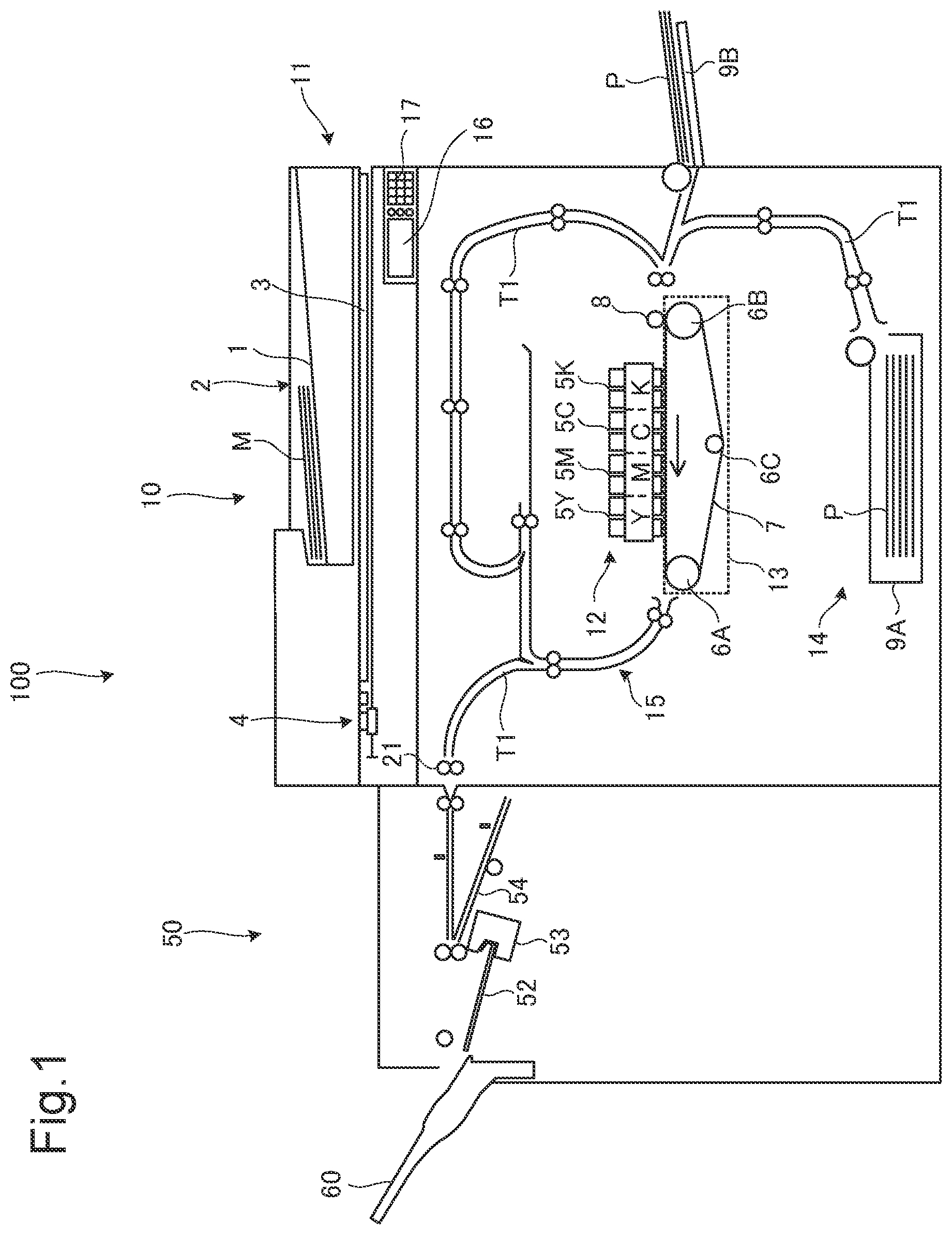
is a cross-sectional view showing a structure of an image forming apparatus and a postprocessing device, constituting an image forming system;
is a block diagram showing an internal configuration of the image forming apparatus and the postprocessing device;
is a partially enlarged cross-sectional view of the postprocessing device;
A and B are flowcharts each showing a first recording sheet shunting process;
A to C are cross-sectional views each showing how a preceding recording sheet is transported;
D and E are cross-sectional views each showing how the preceding recording sheet and a following recording sheet are transported; and
A and B are flowcharts each showing a second recording sheet shunting process.
DETAILED DESCRIPTION
First Embodiment
Hereunder, a first embodiment of the disclosure will be described, with reference to the drawings. is a cross-sectional view showing a structure of an image forming apparatus 10 and a postprocessing device 50 , constituting an image forming system 100 according to the first embodiment of the disclosure. is a block diagram showing an internal configuration of the image forming apparatus 10 and the postprocessing device 50 .
As shown in , the image forming system 100 includes the image forming apparatus 10 , and the postprocessing device 50 connected to the image forming apparatus 10 . The image forming apparatus 10 forms an image on a recording sheet, an example of the recording medium in the disclosure. The postprocessing device 50 performs postprocessing, on the recording sheet on which the image has been formed by the image forming apparatus 10 .
[Configuration of Image Forming Apparatus 10 ]
As shown in , the image forming apparatus 10 is an ink jet recording apparatus. The image forming apparatus 10 includes an image reading device 11 , an image forming device 12 , a transport unit 13 , a paper feeding device 14 , a transport mechanism 15 , a display device 16 , and an operation device 17 .
The image reading device 11 is constituted as an automatic document feeder (ADF), including a document feeding device 2 that transports a source document M placed on a document tray 1 , and a scanner 4 that optically reads the source document M transported by the document feeding device 2 , or placed on a platen glass 3 . The image reading device 11 emits light to the source document from a light emitter of the scanner 4 , and receives the reflected light with a charge-coupled device (CCD) sensor, to thereby read the source document and generate image data representing the source image.
The image forming device 12 includes line heads 5 Y, 5 M, 5 C, and 5 K, respectively corresponding to yellow, magenta, cyan, and black colors. The image forming device 12 ejects ink droplets of the respective colors from the line heads 5 Y, 5 M, 5 C, and 5 K, onto a recording sheet P transported by the transport unit 13 , according to the image data generated by the image reading device 11 , thereby forming a color image.
The transport unit 13 includes a drive roller 6 A, a follower roller 6 B, a tension roller 6 C, a transport belt 7 , and an adsorption roller 8 . The drive roller 6 A is connected to a drive motor, to be driven to rotate counterclockwise. The transport belt 7 is an endless belt engaged over the drive roller 6 A, the follower roller 6 B, and the tension roller 6 C.
The transport belt 7 rotates counterclockwise, so as to follow up the rotation of the drive roller 6 A. The follower roller 6 B and the tension roller 6 C rotate counterclockwise, so as to follow up the rotation of the transport belt 7 . The adsorption roller 8 is opposed to the follower roller 6 B, in contact with the transport belt 7 . The adsorption roller 8 electrically charges the transport belt 7 , to thereby electrostatically adsorb the recording sheet P delivered from the paper feeding device 14 , to the transport belt 7 .
The paper feeding device 14 includes a paper cassette 9 A and a manual bypass tray 9 B. The paper feeding device 14 draws out the recording sheets P stored in the paper cassette 9 A or the manual bypass tray 9 B one by one, with a pickup roller rotated by a paper feeding motor, and delivers the recording sheet P to the sheet transport path T 1 .
The transport mechanism 15 includes a sheet transport path T 1 extending from the paper feeding device 14 to the postprocessing device 50 via the transport unit 13 , a plurality of transport roller pairs provided close to the sheet transport path T 1 , a delivery roller pair 21 , and a transport motor. The transport mechanism 15 rotates the transport roller pairs and the delivery roller pair 21 by driving the transport motor, to transport the recording sheet P along the sheet transport path T 1 , and deliver the recording sheet P to the postprocessing device 50 through the delivery roller pair 21 .
The display device 16 is constituted of, for example, a liquid crystal display (LCD) or an organic light-emitting diode (OLED) display. The display device 16 displays various types of screens related to the functions that the image forming apparatus 10 is configured to perform.
The operation device 17 includes a plurality of hard keys, such as a start key for instructing the start of various operations, relevant to the functions that the image forming apparatus 10 is configured to perform. The operation device 17 also includes a touch panel overlaid on the display device 16 . The user can input, through the operation device 17 , various types of information, such as the instruction relevant to the functions that the image forming apparatus 10 is configured to perform.
As shown in , the image forming apparatus 10 further includes a control device 18 , a storage device 19 , and an interface (I/F) 20 . The control device 18 includes a processor, a random-access memory (RAM), and a read-only memory (ROM). The processor is, for example, a central processing device (CPU), a micro processing device (MPU), or an application specific integrated circuit (ASIC).
The control device 18 is electrically connected to the image reading device 11 , the image forming device 12 , the transport unit 13 , the paper feeding device 14 , the transport mechanism 15 , the display device 16 , the operation device 17 , the storage device 19 , and the I/F 20 .
The control device 18 acts as a controller 21 , when the processor executes a control program stored in the ROM or the storage device 19 . Here, the controller 21 may be constituted in the form of a logic circuit, instead of being realized by the operation according to the control program. The controller 21 controls the operation of each component of the image forming apparatus 10 .
The storage device 19 is a large-capacity memory unit such as a solid state drive (SSD) or a hard disk drive (HDD). The storage device 19 stores therein various types of data, and various control programs for realizing the basic functions of the image forming apparatus 10 .
To the I/F 20 , the postprocessing device 50 is connected. The I/F 20 includes a plurality of terminals for electrical connection to the postprocessing device 50 .
A power source is provided for each of the components of the image forming apparatus 1 , so that those components are activated with the poser from the power source.
[Configuration of Postprocessing Device 50 ]
is a partially enlarged cross-sectional view of the postprocessing device 50 . Referring to , the postprocessing device 50 includes a casing, having a sheet inlet 51 A formed in a first side face on the side of the image forming apparatus 10 , and a delivery port 51 B formed in a second side face on the opposite side of the first side face. The postprocessing device 50 includes, inside the casing, a processing tray 52 , a stapler 53 , a sheet transport path T 2 , a sidetrack 54 , a first transport roller 55 A, a second transport roller 55 B, a first detector 56 , a second detector 57 , a sidetrack roller 58 , a delivery roller 59 , and an output tray 60 .
The processing tray 52 in inclined, such that one end portion on the side of the stapler 53 is located on the lower side of the other end portion. The processing tray 52 includes a bent portion, formed so as to bend upward from the one end portion. A plurality of recording sheets P delivered to the processing tray 52 are aligned with each other, because of an end portion of each of the recording sheets P being abutted against the bent portion.
The stapler 53 performs a stapling operation as the postprocessing, including binding a bundle S of the recording sheets P placed on the processing tray 52 , with a stapling needle. Here, the stapler 53 exemplifies the postprocessing unit in the disclosure.
The sheet transport path T 2 extends toward the processing tray 52 , from the sheet inlet 51 A. The sidetrack 54 is located at a position different from the sheet transport path T 2 (in this embodiment, on the lower side of the sheet transport path T 2 ), and extends toward the second transport roller 55 B.
The first transport roller 55 A defines a nip region in collaboration with the follower roller. The first transport roller 55 A is driven by a motor of the driver 62 so as to rotate clockwise (hereinafter, forward rotation), to thereby transport the recording sheet P transported from the image forming apparatus 10 via the sheet inlet 51 A, along the sheet transport path T 2 at a predetermined transport speed. Here, the clockwise direction exemplifies the first direction and the reverse direction in the disclosure.
The second transport roller 55 B defines a nip region in collaboration with the follower roller. The second transport roller 55 B is driven by a motor of the driver 62 so as to rotate forward, to thereby transport the recording sheet P delivered from the first transport roller 55 A, toward the processing tray 52 . The second transport roller 55 B is also driven by the motor of the driver 62 so as to rotate counterclockwise (hereinafter, reverse rotation), to thereby cause the recording sheet P delivered from the first transport roller 55 A to move backward, and enter into the sidetrack 54 . Here, the counterclockwise direction exemplifies the second direction and the forward direction in the disclosure.
The first detector 56 is provided close to the sheet transport path T 2 . The first detector 56 detects whether the recording sheet P is present, at a predetermined position on the sheet transport path T 2 . The second detector 57 is provided close to the sidetrack 54 . The second detector 57 detects whether the recording sheet P is present, at a predetermined position on the sidetrack 54 .
The type of the first detector 56 and the second detector 57 is not specifically limited but, for example, a reflective photosensor or a transmissive photosensor may be employed. The first detector 56 and the second detector 57 each output an ON signal upon detecting the presence of the recording sheet P, and output an OFF signal when the presence of the recording sheet P is undetected.
The sidetrack roller 58 is provided on the sidetrack 54 , so as to make contact with the recording sheet P. The sidetrack roller 58 is driven by a motor of the driver 62 so as to rotate forward, to thereby move the recording sheet P on the sidetrack 54 in the direction away from the second transport roller 55 B, toward the second detector 57 (hereinafter, shunting direction). The sidetrack roller 58 is also driven by the motor of the driver 62 so as to rotate reversely, to thereby deliver the recording sheet P on the sidetrack 54 , to the second transport roller 55 B.
In this embodiment, a first stop position for locating the leading edge of the recording sheet P of A4 size in the shunting direction, and a second stop position for locating the trailing edge of the recording sheet P in the shunting direction, are defined in advance on the sidetrack 54 . The second detector 57 is located at the position corresponding to the first stop position.
The delivery roller 59 is provided on the upper side of the processing tray 52 . The delivery roller 59 can be elevated and lowered, by an elevation device. One end portion of the output tray 60 is located on the lower side of the delivery port 51 B on the second side face of the casing. The delivery roller 59 is driven by the motor of the driver 62 so as to rotate forward, in contact with the bundle S of the recording sheets P on the processing tray 52 , to thereby deliver the bundle S of the recording sheets P to the output tray 60 , through the delivery port 51 B.
As shown in , the postprocessing device 50 further includes a control device 61 , a driver 62 , a storage device 63 , and an I/F 64 . The control device 61 includes a processor, a RAM, and a ROM. The processor is, for example, a CPU, an MPU, or an ASIC. The control device 61 is electrically connected to the driver 62 , the storage device 63 , the I/F 64 , the stapler 53 , the first detector 56 , and the second detector 57 .
The control device 61 acts as a controller 65 , when the processor executes a control program stored in the ROM or the storage device 63 . Here, the controller 65 may be constituted in the form of a logic circuit, instead of being realized by the operation according to the control program. The controller 65 controls the operation of each component of the postprocessing device 50 .
The driver 62 includes a plurality of motors, respectively connected to the first transport roller 55 A, the second transport roller 55 B, the sidetrack roller 58 , and the delivery roller 59 . The driver 62 causes the first transport roller 55 A, the second transport roller 55 B, the sidetrack roller 58 , and the delivery roller 59 to rotate, by driving the corresponding motors.
The storage device 63 is a large-capacity memory unit such as a solid state drive (SSD) or a hard disk drive (HDD). The storage device 63 stores therein various types of data, and various control programs for realizing the basic functions of the postprocessing device 50 . As an example of the control programs, the storage device 63 contains a first program for executing a first recording sheet shunting process according to the first embodiment.
The controller 65 performs the first recording sheet shunting process as follows, by operating according to the first program. When the trailing edge of a preceding recording sheet P 1 comes out of the sheet transport path T 2 , the controller shunts the preceding recording sheet P 1 to the sidetrack 54 , by causing the second transport roller 55 B to rotate reversely; transports the preceding recording sheet P 1 on the sidetrack 54 in the shunting direction X 2 , by causing the sidetrack roller 58 to rotate forward; acquires the length of the preceding recording sheet P 1 in the transport direction X 1 , on the basis of a transit time of the preceding recording sheet P 1 obtained from the detection result of the first detector 56 , and the transport speed of the preceding recording sheet P 1 ; determines, on the basis of the length of the preceding recording sheet P 1 in the transport direction X 1 , a timing to stop the rotation of the sidetrack roller 58 such that, when the sidetrack roller 58 is made to start rotating at a predetermined reference timing to start based on the detection result from the first detector 56 , the leading edge of a recording sheet P 2 , following the preceding recording sheet P 1 being transported by the forward rotation of the second transport roller 55 B, becomes aligned with the leading edge of the preceding recording sheet P 1 , and stops the forward rotation of the sidetrack roller 58 at the timing to stop determined; and transports the following recording sheet P 2 and the preceding recording sheet P 1 on the sidetrack 54 in an overlapping manner, to the processing tray 52 with the second transport roller 55 B, by causing the second transport roller 55 B to rotate forward and causing the sidetrack roller 58 to rotate reversely at the reference timing to start.
To the I/F 64 , the image forming apparatus 10 is connected. The I/F 64 includes a plurality of terminals for electrical connection to the image forming apparatus 10 .
A power source is provided for each of the components of the postprocessing device 50 , so that those components are activated with the poser from the power source.
[Operation]
A and B are flowcharts each showing the first recording sheet shunting process. A illustrates how the preceding recording sheet P 1 is transported. B and C each illustrate how the preceding recording sheet P 1 is shunted. D and E each illustrate how the preceding recording sheet P 1 and the following recording sheet P 2 are transported.
Referring to A to E , an operation of the image forming system 100 , performed when executing the first recording sheet shunting process, will be described hereunder. In this embodiment, it will be assumed that the length of the preceding recording sheet P 1 in the transport direction X 1 is equal to or longer than 297 mm.
[Operation of Image Forming Apparatus 10 ]
For example, the user places two sheets of the source document M on the document tray 1 of the document transport device 2 . Then the user inputs, through the touch panel of the operation device 17 , a first instruction to produce two copies from one source document M, and a second instruction to perform the stapling on every two sheets, and presses the start key of the operation device 17 . In this case, the controller 21 of the image forming apparatus 10 transmits, upon detecting that the start key has been pressed, a control signal representing the second instruction to the postprocessing device 50 , via the I/F 20 .
The controller 21 also causes the image reading device 11 to read the source documents M, sequentially transported by the document transport device 2 one by one, and generate the image data representing the source image of two pages. The controller 21 then causes the transport mechanism 15 to sequentially transport four sheets of the recording sheet P toward the postprocessing device 50 along the sheet transport path T 1 , and causes the image forming device 12 to repeatedly form the source images of two pages represented by the image data generated as above, in the order of the pages, on the four recording sheets P transported by the transport mechanism 15 .
[Operation of Postprocessing Device 50 ]
Upon receipt of the control signal via the I/F 64 , the controller 65 of the postprocessing device 50 controls the driver 62 so as to cause the first transport roller 55 A and the second transport roller 55 B to rotate forward. When two recording sheets P, namely the first sheet and the second sheet are sequentially delivered from the image forming apparatus 10 through the sheet inlet 51 A, these two recording sheets P are sequentially transported in the transport direction X 1 along the sheet transport path T 2 , by the forward rotation of the first transport roller 55 A and the second transport roller 55 B.
The two recording sheets P each drop, when the trailing edge thereof in the transport direction X 1 passes the second transport roller 55 B, onto the processing tray 52 because of the gravity. The two recording sheets P each slide downward along the slope of the processing tray 52 , and stop when an end portion is abutted against the bent portion of the processing tray 52 . When the number of recording sheets P indicated by the second instruction (in this case, two recording sheets P) are delivered to the processing tray 52 , the controller 65 instructs the stapler 53 to execute the stapling, on the bundle S of the two recording sheets P placed on the processing tray 52 , and starts to execute the first recording sheet shunting process shown in A and B .
In the first recording sheet shunting process, first the controller 65 controls the driver 62 , so as to cause the first transport roller 55 A and the second transport roller 55 B to rotate forward (step S 10 ). Accordingly, the controller 65 transports, as shown in A , the preceding recording sheet P 1 , namely the third sheet, delivered from the image forming apparatus 10 via the sheet inlet 51 A, in the transport direction X 1 along the sheet transport path T 2 , at a predetermined transport speed.
After step S 10 , the controller 65 repeatedly decides that the preceding recording sheet P 1 has not been detected (NO at step S 11 ), until the first detector 56 detects the preceding recording sheet P 1 . When the preceding recording sheet P 1 passes by the first detector 56 , the first detector 56 outputs the ON signal and the OFF signal to the controller 65 , so that the controller 65 decides that the preceding recording sheet P 1 has been detected (YES at step S 11 ), and acquires the length of the preceding recording sheet P 1 in the transport direction X 1 , on the basis of the transit time of the preceding recording sheet P 1 obtained from the detection result of the first detector 56 , and the transport speed of the preceding recording sheet P 1 (step S 12 ).
To be more specific, the controller 65 acquires the length of the preceding recording sheet P 1 in the transport direction X 1 , by multiplying the time between the input of the ON signal and the input of the OFF signal to the controller 65 , by the transport speed of the preceding recording sheet P 1 . After step S 12 , the controller 65 controls the driver 62 , so as to cause the second transport roller 55 B to rotate reversely, after the trailing edge of the preceding recording sheet P 1 in the transport direction X 1 comes out of the sheet transport path T 2 , and immediately before the trailing edge passes through the second transport roller 55 B, as shown in B (step S 13 ). With such operation, the controller 65 shunts the preceding recording sheet P 1 to the sidetrack 54 .
After step S 13 , the controller 65 controls the driver 62 so as to cause the sidetrack roller 58 to rotate forward, as shown in C (step S 14 ). Accordingly, the controller 65 transports the preceding recording sheet P 1 on the sidetrack 54 , in the shunting direction X 2 . After step S 14 , the controller 65 determines, on the basis of the length of the preceding recording sheet P 1 in the transport direction X 1 , the timing to stop the forward rotation of the sidetrack roller 58 , such that, when the sidetrack roller 58 is made to start rotating at the reference timing to start, the leading edge of the following recording sheet P 2 , transported by the forward rotation of the second transport roller 55 B, becomes aligned with the leading edge of the preceding recording sheet P 1 (step S 15 ).
Here, it will be assumed that the controller 65 defines in advance the time point that the second detector 57 has detected the leading edge of the preceding recording sheet P 1 in the shunting direction X 2 , as the reference timing to stop based on the recording sheet P of the A4 size. At step S 15 , to be more specific, the controller 65 decides whether the length of the preceding recording sheet P 1 in the transport direction X 1 exceeds a predetermined reference length (in this case, 297 mm). Upon deciding that the length of the preceding recording sheet P 1 in the transport direction X 1 is equal to the predetermined reference length (i.e., preceding recording sheet P 1 is of A4 size), the controller 65 sets the timing to stop the sidetrack roller 58 , to the reference timing to stop.
In contrast, upon deciding that the length of the preceding recording sheet P 1 in the transport direction X 1 exceeds the reference length, the controller 65 calculates the difference between the length of the preceding recording sheet P 1 in the transport direction X 1 and the reference length. Then the controller 65 sets the timing to stop the sidetrack roller 58 , to the time point delayed from the reference timing to stop, by a time obtained by dividing the calculated difference by the moving speed of the preceding recording sheet P 1 on the sidetrack 54 .
After step S 15 , the controller 65 repeatedly decides that the leading edge of the preceding recording sheet P 1 in the shunting direction X 2 has not been detected (NO at step S 16 ), until the second detector 57 detects the leading edge in the shunting direction X 2 . When the leading edge of the preceding recording sheet P 1 in the shunting direction X 2 passes the second detector 57 , the second detector 57 outputs the ON signal to the controller 65 , so that the controller 65 decides that the leading edge in the shunting direction X 2 has been detected (YES at step S 16 ), and controls the driver 62 so as to stop the forward rotation of the sidetrack roller 58 , at the timing to stop determined as above (step S 17 ).
As result, the preceding recording sheet P 1 is placed on the sidetrack 54 , with the trailing edge in the shunting direction X 2 coinciding with the predetermined second stop position. After step S 17 , the controller 65 controls the driver 62 , so as to cause the first transport roller 55 A and the second transport roller 55 B to rotate forward (step S 18 ). Accordingly, the following recording sheet P 2 , namely the fourth sheet, delivered from the image forming apparatus 10 via the sheet inlet 51 A, is transported in the transport direction X 1 along the sheet transport path T 2 , as shown in D .
At this point, since the stapling has already been executed, the controller 65 controls the elevation device so as to lower the delivery roller 59 to enter into contact with the bundle S of the recording sheets P on the processing tray 52 , and controls the driver 62 to cause the delivery roller 59 to rotate forward. As result, the bundle S of the recording sheets P on the processing tray 52 is delivered to the output tray 60 , via the delivery port 51 B.
After step S 18 , the controller 65 repeatedly decides that the following recording sheet P 2 has not been detected (NO at step S 19 ), until the first detector 56 detects the following recording sheet P 2 . When the following recording sheet P 2 passes the first detector 56 , the first detector 56 outputs the ON signal and the OFF signal to the controller 65 , so that the controller 65 decides that the following recording sheet P 2 has been detected (YES at step S 19 ), and controls the driver 62 so as to cause the sidetrack roller 58 to rotate reversely, at the predetermined reference timing to start (step S 20 ).
Here, it will be assumed that the controller 65 defines in advance the time point delayed by a predetermined time (in this case, 0.5 seconds) from the time point that the OFF signal has been inputted by the first detector 56 because of the passing of the following recording sheet P 2 , as the reference timing to start based on the recording sheet P of the A4 size.
As result of the operation of step S 20 , the preceding recording sheet P 1 on the sidetrack 54 is moved in a direction S 3 toward the second transport roller 55 B, as shown in E . When the preceding recording sheet P 1 reaches the second transport roller 55 B, the preceding recording sheet P 1 and the following recording sheet P 2 are delivered to the processing tray 52 by the second transport roller 55 B in an overlapping manner, with the respective leading edges in the transport direction X 1 aligned with each other.
Now, with the aforementioned known postprocessing device, the preceding recording sheet standing by is stacked on the following recording sheet, to be transported together. Although it is preferable that the leading edge of the preceding recording sheet is aligned with the leading edge of the following recording sheet, the leading edges may fail to be aligned, when the recording sheets are different in size.
To avoid the mentioned problem, the known technique includes controlling the rotation of the shunting drum, so as to bring the leading edge of the preceding recording sheet to a predetermined position, thereby aligning the leading edge of the preceding recording sheet with the leading edge of the following recording sheet. In this case, however, the space for locating the shunting drum is required, and therefore the overall size of the device is increased.
With the configuration according to the first embodiment, in contrast, the controller 65 acquires the length of the preceding recording sheet P 1 in the transport direction X 1 , on the basis of the transit time of the preceding recording sheet P 1 obtained from the detection result of the first detector 56 , and the transport speed of the preceding recording sheet P 1 , and determines, on the basis of the length of the preceding recording sheet P 1 in the transport direction X 1 , the timing to stop the rotation of the sidetrack roller 58 such that, when the sidetrack roller 58 is made to start rotating at the predetermined reference timing to start, the leading edge of the following recording sheet P 2 transported by the forward rotation of the second transport roller 55 B, becomes aligned with the leading edge of the preceding recording sheet P 1 .
Therefore, the preceding recording sheet P 1 and the following recording sheet P 2 can be transported, with the respective leading edges aligned with each other, irrespective of the difference in length of the preceding recording sheet P 1 in the transport direction X 1 . In addition, since the sidetrack 54 is employed to shunt the preceding recording sheet P 1 , the preceding recording sheet P 1 can be shunted without the need to increase the size of the device, unlike the case where the shunting drum is employed.
According to the first embodiment, further, when the length of the preceding recording sheet P 1 in the transport direction X 1 is equal to the predetermined reference length, the controller 65 sets the timing to stop the sidetrack roller 58 to the predetermined reference timing to stop based on the detection result from the second detector 57 . When the length of the preceding recording sheet P 1 in the transport direction X 1 exceeds the reference length, the controller 65 calculates the difference between the length of the preceding recording sheet P 1 in the transport direction X 1 and the reference length, and sets the timing to stop the sidetrack roller 58 to the time point delayed from the reference timing to stop by the time obtained by dividing the difference by the moving speed of the preceding recording sheet P 1 on the sidetrack 54 .
Thus, the timing to stop the sidetrack roller 58 is determined on the basis of the reference timing to stop corresponding to the reference length, and the moving speed of the preceding recording sheet P 1 , and therefore the timing to stop can be easily and accurately determined.
Second Embodiment
The image forming system 100 according to a second embodiment of the disclosure is configured similarly to the image forming system 100 according to the first embodiment, except that the storage device 63 of the postprocessing device 50 contains a second program for executing a second recording sheet shunting process, instead of the first program. The description of the same components and functions, as those of the image forming system 100 according to the first embodiment, will not be repeated.
In the second embodiment, the controller 65 of the postprocessing device 50 performs the second recording sheet shunting process as follows, by operating according to the second program. When the trailing edge of the preceding recording sheet P 1 comes out of the sheet transport path T 2 , the controller 65 shunts the preceding recording sheet P 1 to the sidetrack 54 by causing the second transport roller 55 B to rotate reversely; transports the preceding recording sheet P 1 on the sidetrack 54 in the shunting direction X 2 , by causing the sidetrack roller 58 to rotate forward; stops the rotation of the sidetrack roller 58 at a predetermined reference timing to stop based on the detection result from the second detector 57 ; acquires the length of the preceding recording sheet P 1 in the transport direction X 1 , on the basis of a transit time of the preceding recording sheet P 1 obtained from the detection result of the first detector 56 , and the transport speed of the preceding recording sheet P 1 ; determines, on the basis of the length of the preceding recording sheet P 1 in the transport direction X 1 , a timing to start the rotation of the sidetrack roller 58 such that, when the sidetrack roller 58 is made to stop rotating at the reference timing to stop, the leading edge of a recording sheet P 2 , following the preceding recording sheet P 1 being transported by the forward rotation of the second transport roller, becomes aligned with the leading edge of the preceding recording sheet P 1 ; and transports the following recording sheet P 2 and the preceding recording sheet P 1 on the sidetrack 54 in an overlapping manner, to the processing tray 52 with the second transport roller 55 B, by causing the second transport roller 55 B to rotate forward and causing the sidetrack roller 58 to rotate reversely at the timing to start determined.
[Operation of Postprocessing Device 50 ]
A and B are flowchart each showing the second recording sheet shunting process. Referring to A and B , an operation of the image forming system 100 , performed when executing the second recording sheet shunting process, will be described hereunder. In this embodiment, it will be assumed that the length of the preceding recording sheet P 1 in the transport direction X 1 is equal to or longer than 297 mm.
[Operation of Postprocessing Device 50 ]
The controller 65 of the postprocessing device 50 starts to execute the second recording sheet shunting process shown in A and B , as in the first embodiment, upon instructing the stapler 53 to execute the stapling on the bundle S of the recording sheets P placed on the processing tray 52 .
In the second recording sheet shunting process, the controller 65 performs the operation of step S 30 to step S 34 , similarly to step S 10 to step S 14 of the first recording sheet shunting process. After step S 34 , the controller 65 repeatedly decides that the leading edge of the preceding recording sheet P 1 in the shunting direction X 2 has not been detected (NO at step S 35 ), until the second detector 57 detects the leading edge in the shunting direction X 2 .
When the leading edge of the preceding recording sheet P 1 in the shunting direction X 2 passes the second detector 57 , the second detector 57 outputs the ON signal to the controller 65 , so that the controller 65 decides that the leading edge in the shunting direction X 2 has been detected (YES at step S 35 ), and controls the driver 62 so as to stop the forward rotation of the sidetrack roller 58 , at the reference timing to stop (step S 36 ). Here, it will be assumed that the controller 65 defines in advance the time point that the second detector 57 has detected the leading edge of the preceding recording sheet P 1 in the shunting direction X 2 , as the reference timing to stop based on the recording sheet P of the A4 size. As result, the preceding recording sheet P 1 is placed on the sidetrack 54 , with the leading edge in the shunting direction X 2 coinciding with the predetermined first stop position.
After step S 36 , the controller 65 determines, on the basis of the length of the preceding recording sheet P 1 in the transport direction X 1 , the timing to start the reverse rotation of the sidetrack roller 58 , such that, when the sidetrack roller 58 is made to stop rotating at the reference timing to stop, the leading edge of the following recording sheet P 2 , transported by the forward rotation of the second transport roller 55 B, becomes aligned with the leading edge of the preceding recording sheet P 1 (step S 37 ). Here, it will be assumed that the controller 65 defines in advance the time point delayed by a predetermined time (in this case, 0.5 seconds) from the time point that the OFF signal has been inputted by the first detector 56 because of the passing of the following recording sheet P 2 , as the reference timing to start based on the recording sheet P of the A4 size.
At step S 37 , to be more specific, the controller 65 decides whether the length of the preceding recording sheet P 1 in the transport direction X 1 exceeds the predetermined reference length (in this case, 297 mm). Upon deciding that the length of the preceding recording sheet P 1 in the transport direction X 1 is equal to the reference length (i.e., preceding recording sheet P 1 is of A4 size), the controller 65 sets the timing to start the rotation of the sidetrack roller 58 , to the reference timing to start.
In contrast, upon deciding that the length of the preceding recording sheet P 1 in the transport direction X 1 exceeds the reference length, the controller 65 calculates the difference between the length of the preceding recording sheet P 1 in the transport direction X 1 and the reference length. Then the controller 65 sets the timing to start the rotation of the sidetrack roller 58 , to the time point delayed from the reference timing to start, by a time obtained by dividing the calculated difference by the moving speed of the preceding recording sheet P 1 on the sidetrack 54 .
After step S 37 , the controller 65 controls the driver 62 , so as to cause the first transport roller 55 A and the second transport roller 55 B to rotate forward (step S 38 ). Accordingly, the following recording sheet P 2 , namely the fourth sheet, delivered from the image forming apparatus 10 via the sheet inlet 51 A, is transported in the transport direction X 1 along the sheet transport path T 2 , as shown in D .
At this point, since the stapling has already been executed, the controller 65 controls the elevation device so as to lower the delivery roller 59 to enter into contact with the bundle S of the recording sheets P on the processing tray 52 , and controls the driver 62 to cause the delivery roller 59 to rotate forward. As result, the bundle S of the recording sheets P on the processing tray 52 is delivered to the output tray 60 , via the delivery port 51 B.
After step S 38 , the controller 65 repeatedly decides that the following recording sheet P 2 has not been detected (NO at step S 39 ), until the first detector 56 detects the following recording sheet P 2 . When the following recording sheet P 2 passes the first detector 56 , the first detector 56 outputs the ON signal and the OFF signal to the controller 65 , so that the controller 65 decides that the following recording sheet P 2 has been detected (YES at step S 39 ), and controls the driver 62 so as to cause the sidetrack roller 58 to rotate reversely, at the timing to start determined as above (step S 40 ).
As result of the operation of step S 40 , the preceding recording sheet P 1 on the sidetrack 54 is moved in the direction X 3 toward the second transport roller 55 B, as shown in E . When the preceding recording sheet P 1 reaches the second transport roller 55 B, the preceding recording sheet P 1 and the following recording sheet P 2 are delivered to the processing tray 52 by the second transport roller 55 B in the overlapping manner, with the respective leading edges in the transport direction X 1 aligned with each other.
According to the second embodiment, the controller 65 acquires the length of the preceding recording sheet P 1 in the transport direction X 1 , on the basis of the transit time of the preceding recording sheet P 1 obtained from the detection result of the first detector 56 , and the transport speed of the preceding recording sheet P 1 , and determines, on the basis of the length of the preceding recording sheet P 1 in the transport direction X 1 , the timing to start the rotation of the sidetrack roller 58 such that, when the sidetrack roller 58 is made to stop rotating at the reference timing to stop, the leading edge of the following recording sheet P 2 transported by the forward rotation of the second transport roller 55 B, becomes aligned with the leading edge of the preceding recording sheet P 1 .
Therefore, the preceding recording sheet P 1 and the following recording sheet P 2 can be transported, with the respective leading edges aligned with each other, irrespective of the difference in length of the preceding recording sheet P 1 in the transport direction X 1 .
According to the second embodiment, further, when the length of the preceding recording sheet P 1 in the transport direction X 1 is equal to the predetermined reference length, the controller 65 sets the timing to start the rotation of the sidetrack roller 58 to the predetermined reference timing to start based on the detection result from the first detector 56 . When the length of the preceding recording sheet P 1 in the transport direction X 1 exceeds the reference length, the controller 65 calculates the difference between the length of the preceding recording sheet P 1 in the transport direction X 1 and the reference length, and sets the timing to start the rotation of the sidetrack roller 58 to the time point delayed from the reference timing to start by the time obtained by dividing the difference by the moving speed of the preceding recording sheet P 1 on the sidetrack 54 .
Thus, the timing to start the rotation of the sidetrack roller 58 is determined on the basis of the reference timing to start corresponding to the reference length, and the moving speed of the preceding recording sheet P 1 , and therefore the timing to start can be easily and accurately determined.
[Other Variations]
Although the postprocessing device 50 includes the stapler 53 as the postprocessing unit in the foregoing embodiments, the disclosure is not limited to such embodiments. For example, the postprocessing device 50 may include, as the postprocessing unit, a folding device that folds the recording sheet P on the processing tray 52 , or a punching device that perforates the recording sheet P on the processing tray 52 .
According to the foregoing embodiments, the controller 65 starts to execute the first recording sheet shunting process or the second recording sheet shunting process, while the stapler 53 is executing the stapling. However, the disclosure is not limited to such embodiments. For example, the controller 65 may start to execute the first recording sheet shunting process or the second recording sheet shunting process, when the stapling operation is completed.
Further, although the controller 65 shunts only a single recording sheet P to the sidetrack 54 in the foregoing embodiments, the disclosure is not limited to such embodiments. For example, the controller 65 may shunt two recording sheets P to the sidetrack 54 . In this case, the controller 65 may determine the timing to stop or start the rotation of the sidetrack roller 58 for the second recording sheet P, on the basis of the length of the second recording sheet P in the transport direction X 1 , or determine the timing to stop or start on the basis of the length of the first or second recording sheet P, whichever is longer, in the transport direction X 1 .
Although the image forming device 12 is configured to form an image on the recording sheet P in the foregoing embodiment, the disclosure is not limited to such embodiment. The image forming device 12 may form an image on a different recording medium, other than the recording sheet. For example, an overhead projector (OHP) sheet may be employed, to form an image.
The disclosure may be modified in various manners, without limitation to the configuration according to the foregoing embodiments. For example, although the image forming apparatus 10 is exemplified by the color multifunction peripheral in the embodiments, other types of image forming apparatus, such as a monochrome multifunction peripheral, a copier, or a facsimile machine may be employed instead. In addition, a laser-based image forming apparatus may be employed as the image forming apparatus 10 , in place of the ink jet recording apparatus.
Further, the configurations and processings described in the foregoing embodiment and variations with reference to to B are merely exemplary, and in no way intended to limit the disclosure to those configurations and processings.
While the present disclosure has been described in detail with reference to the embodiments thereof, it would be apparent to those skilled in the art the various changes and modifications may be made therein within the scope defined by the appended claims.
Figures (12)
Citations
This patent cites (5)
- US20050067777
- US20120091648
- US20130147106
- US2012254872
- US2015044657