Semi-constrained Anchoring System
Abstract
Systems, devices, and associated methods for correcting spinal column deformities that help minimize a number of attachment anchors utilized for correction, facilitate use of straight or contoured rods, and/or help promote a more natural, physiologic motion of the spinal column.
Claims (10)
1. A rod anchor for correcting a spinal deformity comprising: a mounting portion configured to secure the rod anchor to a first bony element and including a pedestal; a sleeve having a revolute, convex outer surface and a sleeve passage configured to receive a rod; and a ring-shaped receptacle portion supported by the pedestal, the ring shaped portion having a revolute concave inner surface defining a receptacle passage, the receptacle passage having a longitudinal axis passing through a center of the passage and configured to capture and substantially complementarily fit the sleeve such that the rod received within the sleeve is pivotable in pitch and yaw about a pivot point at a center of the sleeve passage while being constrained from laterally translating towards the revolute concave inner surface.
7. A rod anchor for correcting a spinal deformity comprising: a mounting portion configured to secure the rod anchor to a first bony element and including a pedestal and a stem extending from the pedestal; a substantially spherical sleeve having a revolute, convex outer surface defining a sleeve passage configured to receive a rod; and a ring-shaped receptacle portion fixed relative to the mounting portion and supported by the stem, the receptacle portion having a revolute concave inner surface defining a receptacle passage, the receptacle passage having a longitudinal axis passing through a center of the receptacle passage, the receptacle passage defined by a substantially spherical mating face within the ring-shaped receptacle portion configured to allow the sleeve with the rod received therethrough to pivot in pitch and yaw about the longitudinal axis while being constrained from laterally translating relative to the longitudinal axis.
8. A rod anchor for correcting a spinal deformity comprising: a mounting portion configured to secure the rod anchor to a first bony element and including a pedestal and a stem extending from the pedestal; a sleeve having a revolute, convex outer surface and a sleeve passage configured to receive a rod; and a ring-shaped receptacle portion having a revolute concave inner surface defining a receptacle passage, the receptacle passage having a longitudinal axis passing through a center of the receptacle passage, the receptacle passage configured to receive a rod therethrough such that the rod received within the sleeve is pivotable in pitch and yaw about a pivot point at a center of the sleeve passage while being constrained from laterally translating toward the revolute concave inner surface, and an outside surface from which the stem extends transverse to the longitudinal axis.
Show 7 dependent claims
2. The rod anchor according to claim 1 , wherein the sleeve passage is configured to allow a rod received therethrough to slide longitudinally within the passage.
3. The rod anchor according to claim 1 , wherein the revolute concave inner surface is configured to allow the sleeve received therethrough to roll about the pivot point.
4. The rod anchor according to claim 1 , wherein the pedestal extends along a longitudinal axis extending in a direction parallel to the longitudinal axis of the receptacle passage and the pedestal has a center aligned with the center of the receptacle portion.
5. The rod anchor according to claim 4 , wherein the longitudinal axis of the pedestal is laterally offset from the longitudinal axis of the receptacle passage.
6. The rod anchor according to claim 1 , wherein the sleeve is allowed relative rotational and angular movement with respect to the receptacle portion while captured within the receptacle passage.
9. The rod anchor according to claim 8 , wherein the pedestal comprises a plate attached to the stem, the plate defining a first hole configured to receive a fastener to secure the plate to a first bony element.
10. The rod anchor of claim 8 , wherein the pedestal extends transverse to the stem and has a longitudinal axis extending parallel to the longitudinal axis of the receptacle passage such that the longitudinal axis of the pedestal is laterally offset from the longitudinal axis of the receptacle passage, wherein center points of the receptacle portion, stem and pedestal are aligned.
Full Description
Show full text →
CROSS-REFERENCE TO RELATED APPLICATIONS
The present application is a continuation of U.S. patent application Ser. No. 15/175,514, filed on Jun. 7, 2016, which is a continuation of U.S. patent application Ser. No. 13/722,690 (now U.S. Pat. No. 9,358,044), filed Dec. 20, 2012, which is a continuation of U.S. patent application Ser. No. 12/411,562 (now U.S. Pat. No. 8,357,183), filed Mar. 26, 2009, all of which are incorporated herein by reference.
BACKGROUND
Many systems have been utilized to treat spinal deformities such as scoliosis, spondylolisthesis, and a variety of others. Primary surgical methods for correcting a spinal deformity utilize instrumentation to correct the deformity as much as possible, as well as implantable hardware systems to rigidly stabilize and maintain the correction. Presently, most of these implantable hardware systems rigidly fix the spinal column or allow limited growth and/or other movement of the spinal column, to help facilitate fusion after the column has been moved to a corrected position.
SUMMARY
Some embodiments relate to systems, devices, and associated methods for correcting spinal column deformities that help minimize a number of attachment anchors utilized for correction, facilitate use of straight or contoured rods, and/or help promote a more natural, physiologic motion of the spinal column.
Some embodiments relate to a system for correcting a spinal deformity between a first vertebra and a second vertebra of a person's spine, where the system includes a substantially rigid rod adapted to extend across the spinal deformity. The system also includes a first rod anchor adapted to be fixed to the first vertebra and to receive a first end of the rod such that the rod is allowed to translate axially relative to the first rod anchor, as well as a second rod anchor adapted to be fixed to the second vertebra and to receive a second end of the rod. A first force directing member is coupled between the rod and the spinal deformity, where the first and second rod anchors are adapted to resist lateral translation of the rod relative to the spine and to allow a longitudinal axis of the rod to change in at least a pitch and a yaw.
Some embodiments relate to exerting a distraction and/or compressive force on a spine by securing first and second rod anchors on a first side of the spine. First and second portions of a rod are received in the first and second rod anchors, respectively, such that the first and second portions are substantially constrained against lateral translation. The first and second portions are able to change in pitch and yaw at the first and second rod anchors, respectively, in response to movement of the spine. First and second stops are located adjacent the first rod anchor and the second rod anchor, respectively. The first side of the spine is distracted and/or compressed by imposing a force on the rod with the first and second stops.
This summary is not meant to be limiting in nature. While multiple embodiments are disclosed herein, still other embodiments of the present invention will become apparent to those skilled in the art from the following detailed description, which shows and describes illustrative embodiments of the invention. Accordingly, the drawings and detailed description are to be regarded as illustrative in nature and not restrictive.
BRIEF DESCRIPTION OF THE DRAWINGS
shows an exemplary system for correcting a spinal deformity, according to some embodiments.
is a bottom view of the system of with some features not shown to facilitate understanding, according to some embodiments.
shows a rod of the system of , according to some embodiments.
shows another rod of the system of , according to some embodiments.
a , 5 b , and 6 show features of an anchor of the system of , according to some embodiments.
show features of another anchor of the system of , according to some embodiments.
show still another anchor of the system of , according to some embodiments.
shows alternate complementary shapes for limiting roll between pre-selected angular limits, according to some embodiments.
shows a vertebral anchor and first force directing member of the system of , according to some embodiments.
a and 14 b show an adjustment mechanism of the system of , according to some embodiments.
a , 15 b , and 15 c show some stop features of the system of , according to some embodiments.
is a diagrammatical view showing some of the degrees of freedom of the system of , according to some embodiments.
is another diagrammatical view showing some other degrees of freedom of the system of , according to some embodiments.
are other diagrammatical views showing axial translation degrees of freedom, according to some embodiments.
Various embodiments have been shown by way of example in the drawings and are described in detail below. As stated above, the intention, however, is not to limit the invention by providing such examples.
DETAILED DESCRIPTION
Some embodiments relate to a system for correcting spinal deformities, as well as associated methods and devices. In general terms, the system provides for lateral translational corrective force(s) and/or derotational corrective force(s) on a spinal column. Some features of the system include highly adaptive hardware for connecting the system to the spinal column, where the hardware facilitates a more natural range of motion within pre-selected limits and application of such lateral translational and/or derotational corrective force(s).
Various planes and associated directions are referenced in the following description, including a sagittal plane defined by two axes, one drawn between a head (superior) and tail (inferior) of the body and one drawn between a back (posterior) and front (anterior) of the body; a coronal plane defined by two axes, one drawn between a center (medial) to side (lateral) of the body and one drawn between a head (superior) and tail (inferior) of the body; and a transverse plane defined by two axes, one drawn between a back and front of the body and one drawing between a center and side of the body. The terms pitch, roll, and yaw are also used, where roll generally refers to angulation, or rotation, in a first plane through which a longitudinal axis of a body orthogonally passes (e.g., rotation about a longitudinal axis corresponding to the spinal column), pitch refers to angulation, or rotation, in a second plane orthogonal to the first plane, and yaw refers to angulation, or rotation, in a third plane orthogonal to the first and second planes. In some embodiments, pitch is angulation in the sagittal plane, yaw is angulation in the coronal plane, and roll is angulation in the transverse plane.
In various embodiments, changes in pitch, yaw, and/or roll occur concurrently or separately as desired. Moreover, as used herein, “lateral translation” is not limited to translation in the medial-lateral direction unless specified as such.
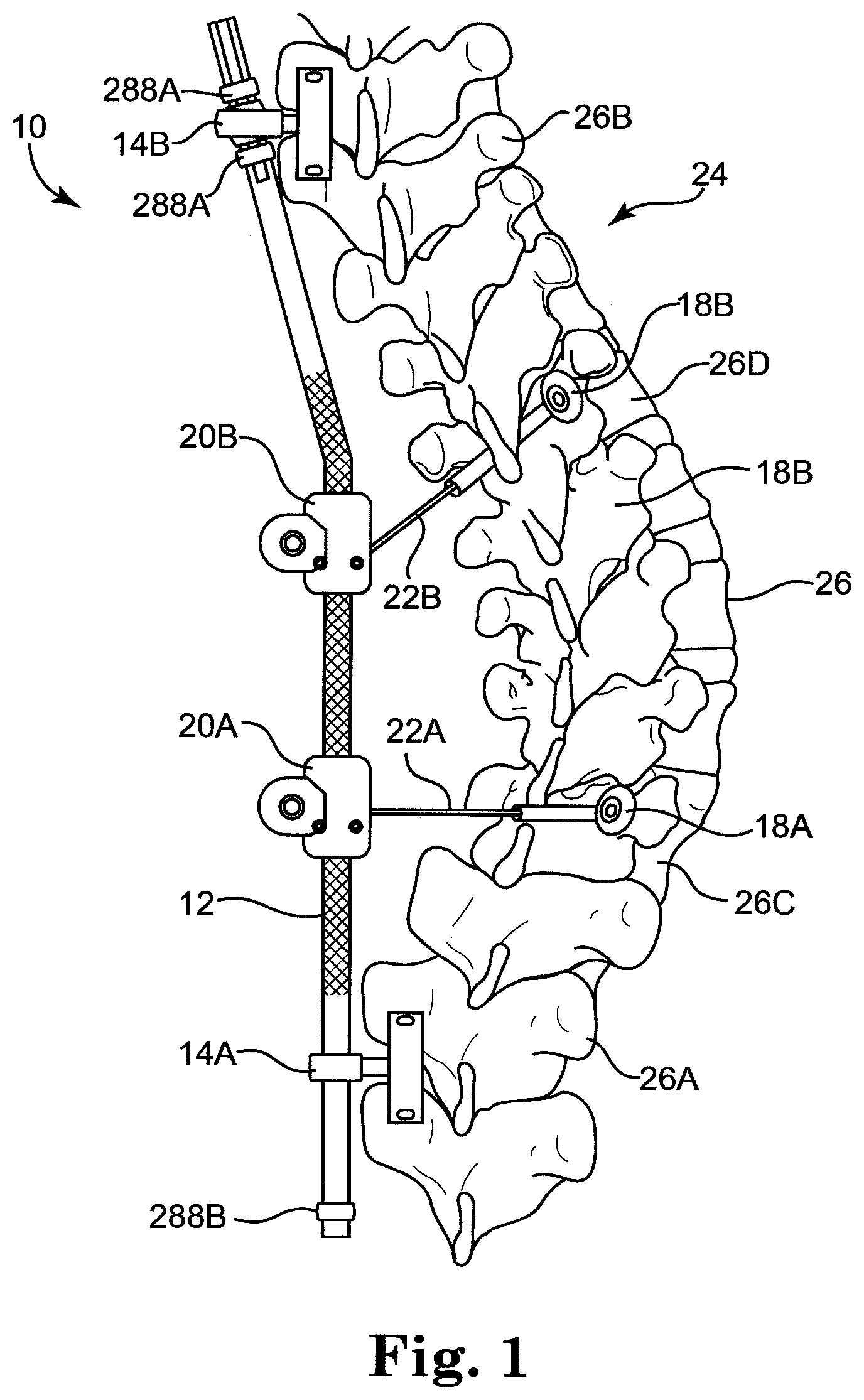
is a perspective view of a system 10 for correcting a spinal deformity, according to some embodiments. The system 10 includes a rod 12 , a plurality of rod anchors 14 , including a first rod anchor 14 A and a second rod anchor 14 B, a plurality of vertebral anchors 18 including a first vertebral anchor 18 A and a second vertebral anchor 18 B, a plurality of adjustment mechanisms 20 including a first adjustment mechanism 20 A and a second adjustment mechanism 20 B, and a plurality of force directing members 22 including a first force directing member 22 A and a second force directing member 22 B. As shown, the system 10 is secured to a spinal column 24 formed of a plurality of vertebrae 26 , including a first vertebra 26 A, a second vertebra 26 B, a third vertebra 26 C, and a fourth vertebra 26 D.
Although the system 10 is shown with two rod anchors 14 , two vertebral anchors 18 , two adjustment mechanisms 20 , and two force directing members 22 , more or fewer are implemented as appropriate. For example, in some embodiments a single vertebral anchor 18 is secured to a vertebra 26 at an apex of a spinal deformation or other location, with a corresponding force directing member 22 and adjustment mechanism 20 coupled to such vertebral anchor 18 .
As shown in , however, the first and second vertebral anchors 18 A, 18 B are fixed to a portion of the spinal column 24 having an abnormal curvature (e.g., scoliosis) in need of correction. The system 10 is optionally used to incrementally bring the spinal column 24 to a more natural curvature, or a single adjustment is made to the system 10 to accomplish the desired curvature. In other embodiments, an abnormal curvature in the spinal column 24 has been adjusted to a more natural curvature using other hardware, prior to or in conjunction with securing the system 10 to the spinal column 24 .
shows the system 10 from a transverse plane view, with portions of the spinal column 24 and system 10 not shown for illustrative purposes. For reference, the rod 12 , the first vertebral anchor 18 A, the first adjustment mechanism 20 A, and the first force directing member 22 A are shown along with the first vertebra 26 A and third vertebra 26 C.
In some embodiments, the rod 12 , also described as an elongate member, is secured to the spinal column 24 at a pre-selected offset from a longitudinal axis of the spinal column 24 . For example, the rod 12 is optionally secured at an offset along a medial-lateral axis ML, or right-left axis, and anterior-posterior axis AP, or back-front axis. In some embodiments, the rod 12 is secured on the left side of the spinal column 24 . As subsequently described, the offset is optionally selected to cause at least a relative lateral translation (e.g., central or medial movement) and derotational shift (e.g., clockwise rotation from the bottom view of ) of selected vertebrae 26 of the spinal column 24 (relative anterior-posterior movement of selected vertebrae 26 can also be accomplished) such that the spinal column 24 exhibits a more natural position.
shows the rod 12 having a bend according to some embodiments. In some embodiments, the rod 12 is substantially rigid, defining a substantially round cross-section with a mean diameter of about 6 mm and being formed of a suitable biocompatible material, such as titanium alloy ASTM F136. The rod 12 is adapted, or otherwise structured, to extend along the spinal column 24 . In , the bend of the rod 12 is generally shown for illustrative purposes. In various embodiments, the rod 12 is bent in one or more of the sagittal and coronal planes. If desired, the rod 12 incorporates some flex, or springiness while substantially rigidly retaining its shape. The rod 12 is optionally formed of a variety of materials, including stainless steel or suitable polymeric materials. Moreover, as subsequently described, the cross-sectional shape of the rod 12 , including various portions thereof, is not limited to circular cross-sections.
As shown in , in some embodiments the rod 12 is contoured or angled to at least partially mimic a curvature (e.g., sagittal plane kyphosis or lordosis or, alternatively, an existing, defective curvature, e.g., kyphosis or lordosis) of a portion of a spinal column. Although shown with a single bend, such that the rod 12 is substantially non-linear, in other embodiments the rod 12 includes substantially curved, non-linear sections, or incorporates combinations of substantially bent, straight, and/or curved sections.
The rod 12 has a longitudinal axis X, as well as a first section 30 , a second section 32 , and an intermediate section 34 between the first and second sections 30 , 32 . Where the rod 12 is substantially straight, the longitudinal axis X is substantially straight. Where the rod 12 is substantially curved or angled, the longitudinal axis X is similarly curved or angled. The sections 30 , 32 , 34 of the rod 12 are optionally continuously formed or are formed as separate, connected parts as desired. In some embodiments, the second section 32 and intermediate section 34 define an inner angle Ia less than 180 degrees, for example a bend angle from about 135 to about 170 degrees, although a variety of bend angles are contemplated.
In some embodiments, at least one or both of the first and second sections 30 , 32 are generally non-round or otherwise define chase features. For example, as shown in , the second section 32 forms at least one flat 36 , the second section 32 having a substantially D-shaped cross-section along at least a portion thereof. In turn, the first section 30 and intermediate section 34 have substantially circular cross-sections, although any of the sections 30 , 32 , 34 optionally have non-circular, cross-sectional shapes as desired (e.g., star-, oval-, or square-shaped cross-sections). As will be subsequently described, a cross-sectional shape of a particular section is optionally used to limit rotation of the rod 12 , although cross-sectional modifications to selectively enhance bending performance and other characteristics of the rod 12 are also contemplated (e.g. I-beam, hexagonal, or other shapes).
At least some of the intermediate section 34 optionally includes a surface treatment, such as surface roughening 38 (e.g., knurling or dimpling), or other treatment (e.g., coatings, plasma treatments, or others) for enhancing friction and/or performance. In turn, portions of the first and second sections 30 , 32 optionally include mirror finishes, surface coatings (e.g., PTFE), or other materials or surface treatments. Though some examples have been provided, various combinations of surface treatments for portions of each of the sections 30 , 32 , 34 are contemplated.
shows a rod 12 A according to some other embodiments. The rod 12 A is substantially straight, or linear, and includes any of the features described in association with the rod 12 as appropriate. In features of the rod 12 A similar to those of the rod 12 are designated with the same reference number as the rod 12 followed by an “A.”
In some embodiments, the rod 12 A is of a two-piece design and includes a rod adjustment mechanism 39 which provides means for increasing an effective length of the rod 12 A. The rod adjustment mechanism 39 is optionally a female threaded sleeve adapted to extend or contract (lengthen or shorten) a gap between pieces of the rod 12 A by turning the adjustment mechanism 39 to engaging threads 37 on the sleeve. The adjustment mechanism 39 optionally has flats or other surface features for receiving a tool (e.g., an open ended wrench). One example of another female, sleeve-type adjustment mechanism generally suitable for use with some embodiments described herein is shown in U.S. Pat. No. 4,078,559, issued Mar. 14, 1978.
Additional examples of rods in accordance with some embodiments of the system 10 are set forth in U.S. application Ser. No. 11/196,952, filed on Aug. 3, 2005 and entitled DEVICE AND METHOD FOR CORRECTING A SPINAL DEFORMITY, as well as Ser. No. 12/134,058, filed on Jun. 5, 2008 and entitled MEDICAL DEVICE AND METHOD TO CORRECT DEFORMITY, the entire contents of both of which are hereby incorporated by reference.
a and 5 b show features of the first rod anchor 14 A, according to some embodiments. As shown in a , the first rod anchor 14 A is adapted, or otherwise structured, to be mounted, or fixed to one or more vertebrae, such as the first vertebra 26 A ( ). The first rod anchor 14 A is further adapted to receive, and includes means for receiving, the rod 12 such that the rod 12 is secured laterally, against lateral translation relative to the first rod anchor 14 A. In some embodiments, the rod 12 is substantially prevented from translating in a direction substantially perpendicular to the longitudinal axis X at the first point P 1 . In turn, the rod 12 (shown in cut-away) is able to slide axially, or translate axially, along the longitudinal axis X, relative to the first rod anchor 14 A through a first pivot point P 1 . The rod 12 is also able to change in pitch, yaw, and roll about the first pivot point P 1 .
The first rod anchor 14 A is optionally formed of biocompatible metallic materials, such as titanium, stainless steel, and/or biocompatible polymeric materials, such as PEEK and/or composite materials. In some embodiments, and as shown in a , the first rod anchor 14 A includes a single-piece housing 40 having receptacle portion 48 adapted, or otherwise structured, to receive the rod 12 . The first rod anchor 14 A further includes a mounting portion 50 adapted to secure the first rod anchor 14 A to one or more vertebrae, such as the first vertebra 26 A and an additional vertebra 26 above or below the first vertebra. In other embodiments, the mounting portion 50 is secured to a single vertebra, such as the first vertebra 26 A (e.g., laterally across the first vertebra 26 A at the pedicles, or at a single point—such as a single pedicle—on the first vertebra 26 A.
As subsequently described, in some embodiments, the housing 40 is of a multi-piece design (e.g., as shown in ).
In some embodiments, the mounting portion 50 , also described as a plate, is adapted to be secured at two or more points, for example spanning between two vertebrae (e.g., the L3-L4 vertebrae) or spanning across a portion of a single vertebra (e.g., pedicle-to-pedicle on a single vertebra).
b shows the receptacle portion 48 in cross-section. According to various embodiments, the receptacle portion 48 is generally ring-shaped and forms a passage 52 having a revolute, convex surface 54 having an upper curve 56 and a lower curve 58 . The receptacle portion 48 is adapted to allow the rod 12 to pass through the passage 52 at the first pivot point P 1 , where the passage 52 defines a minimum effective diameter (e.g., providing appropriate clearance between the rod 12 and receptacle portion 48 ) that allows the rod 12 to slide through passage 52 . The passage 52 also allows the rod 12 to rotate and angulate about the longitudinal axis X at the first pivot point P 1 while minimizing lateral translation or inhibiting substantial lateral translation. In at least this manner, the rod 12 is able to rotate and angulate about the longitudinal axis X at the first pivot point while lateral translation of the rod 12 with respect to the receptacle portion 28 is substantially limited in all planes. In alternate terms, the rod 12 is able to slide within the passage 52 and change in yaw, pitch, and roll at the first pivot point P 1 , while being constrained from side-to-side movement within the passage 52 at the first pivot point P 1 .
In some embodiments, the mounting portion 50 includes a stem 60 and a pedestal 62 , the pedestal 62 having an central portion 64 , a first anchor point 66 , and a second anchor point 68 , the central portion 64 extending between the first and second anchor points 66 , 68 and each of the anchor points 66 , 68 defining a surface suitable for mounting the first rod anchor 14 A to one or more vertebrae 26 . The first and second anchor points 66 , 68 optionally include through holes 70 , 72 , respectively, for receiving a fastener (not shown), such as a pedicle screw or similar device to secure the mounting portion 50 to one or more vertebra 26 , such as the first vertebra 26 A ( ).
In some embodiments, the first rod anchor 14 A is adapted, or otherwise structured, to limit pitch and yaw of the rod 12 to a predefined range. For example, the rod 12 is able to angulate within a range until opposing surfaces of the rod 12 , contact, or bind with the upper and lower curves 56 , 58 of the convex surface 54 . In other words, a radius of curvature of the convex surface 54 is optionally selected to control a range of motion of the rod 12 . In some embodiments, pitch and yaw of the rod 12 is limited to within an angular range Ra of about 60 degrees, for example. As subsequently described in association with the second rod anchor 14 B, various means of limiting roll and/or sliding of the rod 12 within a predefined range are also contemplated.
Although in some embodiments the mounting portion 50 is adapted to receive one or more fasteners as shown in a and 5 b , shows the first rod anchor 14 A with the mounting portion 50 being adapted to act as a fastener, similar to that of a pedicle screw. Thus, the first rod anchor 14 a optionally includes fastener means for securing the first anchor 14 A to one of the vertebra 26 .
Although a , 5 b , and 6 are illustrative of some potential features the system 10 , show a first rod anchor 114 A according to some other embodiments, where is a perspective view with the rod 12 received by the first rod anchor 114 A and is a cross-sectional view of the first rod anchor 114 A with the rod 12 removed. The first rod anchor 114 A is substantially similar to the first rod anchor 14 A, although a housing 140 of the first rod anchor 114 A includes a receptacle portion 148 A and a sleeve portion 148 B. In some embodiments, the sleeve portion 148 B is substantially spherical in shape and the receptacle portion 148 A forms a substantially spherical mating race for the sleeve portion 148 B.
As shown in , the receptacle portion 148 A has a revolute, substantially concave surface 154 A and the sleeve portion 148 B has a revolute, substantially convex surface 154 B. The surfaces 154 A, 154 B are adapted, or otherwise structured, to form a substantially complementary fit with one another, such that the sleeve portion 148 B is captured by the receptacle portion 148 A and is allowed relative rotational and angular movement with respect to the receptacle portion 148 A.
The sleeve portion 148 B has a passage 152 defining a pivot point P 11 through which the rod 12 is able to be slidably received. As with other embodiments, the complementary relationship between the sleeve portion 148 B and the receptacle portion 148 A is optionally designed to restrict, or limit, certain relative movement of the rod 12 with respect to the first rod anchor 114 A. For example, in some embodiments, pitch and yaw of the rod 12 about the pivot point P 11 is limited when opposing surfaces of the rod 12 contact the receptacle portion 148 A proximate a front 156 and/or a back 158 of the receptacle portion 148 A.
is a perspective view of the second rod anchor 14 B and are perspective views of portions thereof. The second rod anchor 14 B is adapted to be fixed, and provides means for fixation to a second vertebra, such as a second vertebra 26 B ( ). The second rod anchor 14 B is further adapted to receive, and provides means for receiving the rod 12 ( ) such that the second rod anchor 14 B limits translational movement of the rod 12 except along the longitudinal axis X and allows the rod 12 to change in at least pitch and yaw about a second pivot point P 2 . The second rod anchor 14 B is optionally substantially similar to the first rod anchor 14 A or first rod anchor 114 A, including any desired combination of previously-described features.
The second rod anchor 14 B is optionally formed of biocompatible metallic materials, such as titanium or stainless steel and/or biocompatible polymeric materials, such as PEEK. In some embodiments, and as shown in , the second rod anchor 14 B includes a housing 200 having receptacle portion 202 and a sleeve portion 204 adapted to receive the rod 12 , the second rod anchor 14 B further including a mounting portion (e.g., similar to the mounting portion 50 of the first rod anchor 14 A) adapted to secure the second rod anchor 14 B to the second vertebra 26 B.
The second rod anchor 14 B is optionally adapted, or otherwise structured, to limit rotation, or roll, of the rod 12 about the longitudinal axis X of the rod 12 ( ). In particular, the second rod anchor 14 B provides means for allowing the rod 12 to angulate without substantial lateral translation relative to the second rod anchor 14 B or substantial rotation about the longitudinal axis X. The sleeve portion 204 is optionally spherical in shape and the receptacle portion 202 forms a substantially spherical mating race, where rotation of the sleeve portion 204 relative to the receptacle portion 202 is substantially inhibited in at least one plane.
shows the receptacle portion 202 and shows the sleeve portion 204 , where the receptacle portion 202 has a revolute, substantially concave inner surface 210 and the sleeve portion 204 has a revolute, substantially convex outer surface 212 . The surfaces 210 , 212 are adapted to form a substantially complementary fit with one another, such that the sleeve portion 204 is captured by the receptacle portion 202 and is allowed relative angular movement with respect to the receptacle portion 202 .
As shown in , the receptacle portion 202 also includes a pair of protrusions 216 (e.g., pins), extending inwardly from and at opposite sides of the inner surface 210 . In turn, as shown in , the sleeve portion 204 has a circumferential groove 218 adapted to slidably receive the protrusions 216 and an internal passage 220 through which the rod 12 is able to be slidably received. A pivot point P 2 is also defined in the passage 220 , the rod 12 passing through the pivot point P 2 .
The passage 220 optionally has a non-circular cross-section (e.g., a substantially D-shaped cross-section corresponding to the second section 32 of the rod 12 ). Upon mating the non-circular cross-sections of the rod 12 and the passage 220 , rotation of the rod 12 relative to the sleeve portion 204 is substantially inhibited.
Upon slidably receiving the protrusions 216 in the circumferential groove 218 the pitch and yaw of the rod 12 are able to change. Relative rotation between the sleeve portion 204 and the receptacle portion 202 , however, is substantially inhibited. Thus, as relative rotation between the sleeve portion 204 and the receptacle portion 202 is also substantially inhibited, relative rotation between the rod 12 and the second rod anchor 14 B is substantially inhibited or limited, allowing the rod 12 to be maintained at a pre-selected rotational position relative to the second rod anchor 14 B. It also should be understood that other cross-sectional shapes for each of the passage 220 and rod 12 can be selected to allow some degree of rotation about the longitudinal axis X within a predefined range, including, for example, that shown in , where the rod 12 is shown with features allowing rotation up to a stop 220 A formed by the sleeve 204 . The cross-sectional shape of the rod 12 is also optionally selected to limit axial translation of the rod 12 as desired.
As with other embodiments, the second rod anchor 14 B is also optionally adapted to restrict, or limit angulation of the rod 12 (e.g., pitch and yaw) with respect to the second rod anchor 14 B. For example, pitch and yaw of the rod 12 about the pivot point P 2 is limited when the rod 12 contacts the receptacle portion 202 proximate a front 222 and/or a back 224 of the receptacle portion 202 . A size and shape of the receptacle and/or sleeve portions 202 , 204 is selected to define such limit(s) as desired.
shows the first vertebral anchor 18 A and first force directing member 22 A from a front elevation view. The first vertebral anchor 18 A, also described as an anchor arm, is adapted to be fixed, and provides means for fixation, to a third vertebra 26 C ( ). As previously described, the first vertebral anchor 18 A is fixed to a portion of the spinal column 24 ( ) having an abnormal curvature in need of correction.
The first and second vertebral anchors 18 A, 18 B are optionally substantially similar, and thus various features of both the first and second vertebral anchors 18 A, 18 B are described in association with the first vertebral anchor 18 A, where when referenced, features of the first vertebral anchor 18 A are designated with reference numbers followed by an “A” and similar features of the second vertebral anchor 18 B are designated with similar reference numbers followed by a “B.”
The first vertebral anchor 18 A includes an arm 250 A and a head 252 A. In some embodiments, the arm 250 A extends from the head 252 A to a terminal end 254 A and is disposed generally perpendicular to the head 252 A. The arm 250 A is optionally rotatable relative to the head 252 B and is adapted to extend across a portion of the third vertebra 26 C, for example, from one side of the spinal column 24 to an opposite side of the spinal column 24 . For example, the first vertebral anchor 18 A is secured to the third vertebra 26 C such that the arm 250 A extends across the third vertebra 26 C through a hole or hollowed portion in the spinous processes (not shown) of the third vertebra 26 C.
The head 252 A is adapted, or is otherwise structured, to be fixed to a portion of the third vertebra 26 C, such as a pedicle of the third vertebra 26 C. The head 252 A optionally includes and/or is adapted to work in conjunction with any of a variety of structures capable of engaging the third vertebra 26 C. For example, the first vertebral anchor 18 A optionally includes a pedicle screw 256 A secured through the head 252 A to a pedicle of the third vertebra 26 C.
The first force directing member 22 A is secured to the first vertebral anchor 18 A at an appropriate location on the first vertebral anchor 18 A. For example, in some embodiments the first force directing member 22 A is secured to the first vertebral anchor 18 A at least at the terminal end 254 A of the arm 250 A such that the first force directing member 22 A extends from the terminal end 254 A of the arm 250 A.
Additional examples of vertebral anchors (also described as “implants”) in accordance with some embodiments of the system 10 are set forth in U.S. application Ser. No. 11/196,952, filed on Aug. 3, 2005 and entitled DEVICE AND METHOD FOR CORRECTING A SPINAL DEFORMITY, as well as Ser. No. 12/134,058, filed on Jun. 5, 2008 and entitled MEDICAL DEVICE AND METHOD TO CORRECT DEFORMITY, the entire contents of both of which are hereby incorporated by reference.
a and 14 b show the first adjustment mechanism 20 A, where b shows the first adjustment mechanism 20 A with a portion removed to illustrate inner features thereof. In some embodiments, the first adjustment mechanism 20 A provides means for securing the first force directing member 22 A to the rod 12 . In some embodiments, the first adjustment mechanism 20 A, also described as a tensioner or coupler, is further adapted to adjust, and provides means for adjusting a length of the first force directing member 22 A. The first and second adjustment mechanisms 20 A, 20 B are optionally substantially similar. Thus, various features of both the first and second adjustment mechanisms 20 A, 20 B are described in association with the first adjustment mechanism 20 A, where features of the first adjustment mechanism 20 A are designated with reference numbers followed by an “A” and similar features of the second adjustment mechanism 20 B are designated with the same reference numbers followed by a “B.”
In some embodiments, the first adjustment mechanism 20 A includes a reel 260 A, a circumferential gear 262 A surrounding the reel 260 A, a vertical gear 264 A in contact with the circumferential gear 262 A, an actuation head 268 A, and a housing 270 A.
The reel 260 A, as well as the circumferential gear 260 A and vertical gear 264 A are maintained at least partially within the housing 270 A. In turn, the housing 270 A is adapted to be secured to the rod 12 . For example, the housing 270 A optionally forms a central lumen through which the rod 12 is receivable. Upon inserting the rod 12 through the central lumen, the housing 270 A is adapted to be clamped onto the rod 12 .
In some embodiments, the housing 270 A incorporates a clamshell design (e.g., a first portion adjustably secured to a second portion) adapted to be tightened onto the rod 12 (e.g., using one or more fasteners). Thus, in some embodiments, the first adjustment mechanism 20 A is substantially fixed with respect to the rod 12 . In other embodiments, however, the first adjustment mechanism 20 A is movable with respect to the rod 12 , for example being able to rotate about the rod 12 .
The first force directing member 22 A is attached or secured to the reel 260 A and passes out of the housing 270 A through an appropriately sized opening in the housing 270 A. Actuation of the vertical gear 264 A via the actuation head 266 A turns the circumferential gear 262 A, which turns the reel 260 A, thus winding (or unwinding, depending on the direction in which the reel 260 A is turned) the first force directing member 22 A about the reel 260 A. Rotation of the reel 260 A in the appropriate direction draws the first force directing member 22 A in toward the first adjustment mechanism 20 A, pulling the first vertebral anchor 18 A ( ) toward the first adjustment mechanism 20 A according to some methods of correcting a spinal defect.
Additional examples of adjustment members (also described as “adjustment mechanisms”), in accordance with some embodiments of the system 10 are set forth in U.S. application Ser. No. 11/196,952, filed on Aug. 3, 2005 and entitled DEVICE AND METHOD FOR CORRECTING A SPINAL DEFORMITY, as well as Ser. No. 12/134,058, filed on Jun. 5, 2008 and entitled MEDICAL DEVICE AND METHOD TO CORRECT DEFORMITY, the entire contents of both of which are hereby incorporated by reference.
As shown in , the first and second force directing members 22 A, 22 B are optionally substantially similar, and thus various features of both the first and second force directing members 22 A, 22 B are described in association with the first force directing member 22 A, where features of the first force directing member 22 A are designated with reference numbers followed by an “A” and similar features of the second force directing member 22 B are designated with similar reference numbers followed by a “B.”
In some embodiments, the first force directing member 22 A is substantially flexible such that the first force directing member 22 A is able to be pivoted in a multiple directions and/or be spooled or wound, for example. Suitable flexible materials for forming the first force directing member 22 A include wire and stranded cables, monofilament polymer materials, multifilament polymer materials, multifilament carbon or ceramic fibers, and others. In some embodiments, the first force directing member 22 A is formed of stainless steel or titanium wire or cable, although a variety of materials are contemplated.
The first force directing member 22 A, also described as a connector or cable, is adapted to be secured to the first vertebral anchor 18 A and the first adjustment member 20 A, the force directing member 22 A defining an effective length between the first adjustment mechanism 20 A and the first vertebral anchor 18 A, and thus the rod 12 (although, in some embodiments, the first force directing member 22 A is secured directly to the rod 12 ). As described, in some embodiments, the first adjustment mechanism 20 A is adapted to modify, and provides means for modifying, the effective length of the force directing member 22 A. The first force directing member 22 A has a body 280 A and extends from a first end 282 A to a second end 284 A.
shows the assembled system 10 . In some embodiments, assembly of the system 10 includes securing the first and second force directing members 22 A, 22 B to the first and second vertebral anchors 18 A, 18 B, respectively. The first and second force directing members 22 A, 22 B are also secured to the first and second adjustment mechanisms 20 A, 20 B. The first and second adjustment mechanisms 20 A, 20 B are secured to the rod 12 . The first and second rod anchors 14 A, 14 B are secured to the first and second vertebrae 26 A, 26 B, respectively. The rod 12 is received in the first and second rod anchors 14 A, 14 B to secure the rod 12 against lateral translation relative to the spinal column 24 . The first and second vertebral anchors 18 A, 18 B are secured to the third and fourth vertebrae 26 C, 26 D. Upon assembly of the system 10 , the first and second adjustment mechanisms 20 A, 20 B are adjusted as desired to pull the first and second vertebral anchors 18 A, 18 B toward the first and second adjustment mechanisms 20 A, 20 B, and thus the rod 12 .
The first force directing member 22 A is assembled to the first vertebral anchor 18 A by securing the first end 282 A of the first force directing member 22 A to the first vertebral anchor 18 A proximate the terminal end 254 A thereof. In some embodiments, the first force directing member 22 A is secured at the terminal end 254 A of the first vertebral anchor 18 A, and extends along at least a portion of the arm 250 A to the head 252 A, although the first force directing member 22 A is attached at any location along the arm 250 A and/or the head 252 A of the first vertebral anchor 18 A as appropriate. The first force directing member 22 A is securable to the first vertebral anchor 18 A via a variety of methods, including welding, adhesives, tying, and/or screw fixation, for example.
The second force directing member 22 B and the second vertebral anchor 18 B are optionally secured or connected together using similar approaches.
As previously described, the first force directing member 22 A extends to the first adjustment mechanism 20 A, enters the housing 250 A, and is wound about the reel 260 A, thereby coupling the first adjustment mechanism 20 A to the first vertebral anchor 18 A as well as the rod 12 . In some embodiments, the first force directing member 22 A is secured to the reel 260 A via welding, screw fixation, adhesives, and/or is sufficiently wound about the reel 260 A for frictional retention of the first force directing member 22 A on the reel 260 A.
The second force directing member 22 A and the second adjustment mechanism 20 B are optionally secured or connected together using similar approaches.
The rod 12 is received by the housings 40 , 200 of the first and second rod anchors 14 A, 14 B, respectively. Features of the first and second rod anchors 14 A, 14 B are selected to limit pitch, yaw, roll, and axial sliding of the rod 12 as desired.
The rod 12 is secured against lateral translation relative to the longitudinal axis of the spinal column 14 by securing the first and second rod anchors 14 A, 14 B to at least the first and second vertebra 26 A, 26 B, respectively. The first rod anchor 14 A is secured to at least the first vertebra 26 A, for example by screwing the first rod anchor 14 A to the first vertebra 26 A (e.g., at or near the transverse processes) using one or more pedicle screws. The second rod anchor 14 B is similarly secured to at least the second vertebra 26 B. The first rod anchor 14 A and/or the second rod anchor 14 B are optionally secured to multiple vertebrae 26 for enhanced stability.
In some embodiments, the rod 12 is attached by the rod anchors 14 A, 14 B to transverse processes on the left side of the spinal column 24 and is able to slide axially relative to the first and/or second rod anchors 14 A, 14 B. In other embodiments, the rod 12 is attached by the rod anchors 14 A, 14 B to the right side of the spinal column 24 , on different sides of the spinal column 24 (e.g., the first rod anchor 14 A on the left side and the second rod anchor 14 B on the right side), or along the mid-line of the spinal column 24 . In other embodiments, the rod 12 is adjustable length to compensate for changes in length of the spinal column 24 . Regardless, the interaction between the rod 12 and the first and second rod anchors 14 A, 14 B helps facilitate growth and more natural movement of the spinal column 24 .
a , 15 b , and 15 c show various stop features 286 for limiting axial sliding, or translation of the rod 12 relative to a rod anchor, such as the first rod anchor 14 A. Generally, sliding of the rod 12 in a particular axial direction is substantially limited, or arrested, when a stop feature 286 engages, or abuts an adjacent rod anchor 14 .
As shown in a , the rod 12 optionally includes a narrowed portion 286 a received in the first rod anchor 14 A with wider, adjacent portions 286 b of the rod 12 limiting axial sliding of the rod 12 . As shown, although axial sliding of the rod 12 is substantially prevented by locating the stop features 286 adjacent the first rod anchor 14 A, there is still some tolerance allowed, or play, as appropriate in the fit between the wider portions 286 b of the rod 12 and the first rod anchor 14 A.
As shown in b , the system 10 optionally includes stops 286 c , or collars, that are fit onto the rod 12 adjacent the first rod anchor 14 A to substantially limit axial sliding of the rod 12 within the first rod anchor 14 A. In some embodiments, the stops 286 c are metal or polymeric collars crimped onto the rod 12 , although a variety of designs and methods of securing are employed as desired. As shown, although axial sliding of the rod 12 is substantially prevented with respect to the first rod anchor 14 A, there is still some limited play or slop as appropriate in the fit between the rod 12 and the stops 286 c.
As shown in c , the system 10 optionally utilizes both a stop 286 c and a narrowed portion 286 a with a wider portion 286 b to limit axial sliding of the rod 12 relative to the first rod anchor 14 A within a desired range of motion. For example, as shown in c , the stop 286 c is located toward an end of the rod 12 on one side of the first rod anchor 14 A and the wider portion 286 b is located on the other side of the first rod anchor 14 A with a desired spacing between the stop 286 c and the wider portion 286 b . Any combination of stop features 286 and spacing are implemented as appropriate.
is a diagrammatical view of a system 10 A similar to that of , where illustrates various degrees of freedom of the rod 12 at the first and second rod anchors 14 A, 14 B, according to some embodiments. As shown, the system 10 A further includes a third vertebral anchor 18 C secured to a fifth vertebra 26 D. The third vertebral anchor is substantially similar to the first and/or second vertebral anchors 18 A, 18 B. The system 10 also optionally includes a corresponding third force directing member 22 C, e.g., a cable or wire, and a third adjustment mechanism 20 C. Although adjustment mechanisms 20 including means for adjusting the effective length of the force directing members 22 have been described, in some embodiments one or more of the adjustment mechanisms 20 acts as a means for coupling a corresponding force directing member to the rod 12 without incorporating such adjustment features. For example, the third adjustment mechanism 20 C, or any of the adjustment mechanisms described herein, is optionally a crimp or fastener means for securing the force directing member 22 C to the rod 12 (e.g., a clamp or crimp).
The rod 12 is bent (e.g., as shown in ) and, as designated by the directional arrows, is free to change in pitch, yaw, and roll, as well as to slide axially along the longitudinal axis X at the first rod anchor 14 A (and thus, at the first pivot point P 1 ) and is free to change in pitch and yaw at the second rod anchor 14 B while relative changes in roll and axial sliding are substantially limited or substantially prevented at the second rod anchor 14 B (and thus, at the second pivot point P 2 ). In some embodiments, collars 288 A or other stop features (such as those previously described) are located on the rod 12 (e.g., crimped onto the rod 12 ) on either side of the second rod anchor 14 B in order to inhibit sliding movement of the rod 12 . In turn, a stop feature 288 B (such as one of those previously described) is located proximate a terminus of the rod 12 in order to help prevent the rod 12 from slipping off the first rod anchor 14 A.
The interaction between the vertebral anchors 18 A, 18 B, adjustment mechanisms 20 A, 20 B, and in particular the flexible nature of their respective coupling through use of the force directing members 22 A, 22 B allows the system 10 to move dynamically with the spinal column 24 , while exerting and/or maintaining a corrective force (e.g., lateral and derotational forces) on the third and fourth vertebrae 26 C, 26 D. In other words, the system 10 is semi-constrained, providing a lateral and derotational anchor point while facilitating at least some degree of natural movement in the spinal column 24 .
Moreover, by limiting rotation, or roll, of the rod 12 , the bend in the rod 12 is oriented and maintained in a desired rotational position. Maintaining the rotational orientation at one end (i.e., at the second rod anchor 14 B) is useful, for example, to help ensure that the bend or shape of the rod 12 consistently follows or otherwise appropriately tracks a desired curvature of a spinal column 24 . Freedom of rotation at the other end of the rod 12 (i.e., at the first rod anchor 14 A), however, still permits the spinal column 24 to have more natural movement while the corrective forces are being applied.
Thus, according to various embodiments, the spinal column 24 (and thus, the person) is able to twist, bend side-to-side, and bend forward-and-backward in a more natural manner while corrective forces are being applied to the spinal column 24 . In some embodiments, the effective lengths of the force directing members 22 A, 22 B are adjusted (e.g., periodically or all at one time), bringing the spinal column into natural alignment, while the system 10 still facilitates a more natural movement of the spinal column 24 (e.g., twisting and bending forward-and-backward and side-to-side) due to the freedom of movement afforded by the system 10 .
is a diagrammatical view of a system 10 B illustrating various degrees of freedom of the rod 112 at the first rod anchor 14 A and a second rod anchor 290 substantially similar to the first rod anchor 14 A, according to some other embodiments of the system 10 . With the system 10 B, the rod 112 is substantially straight ( ) and, as designated by the directional arrows, is free to change in pitch, yaw, and roll, as well as to slide axially along the longitudinal axis X, at each of the first and second rod anchors 14 A, 290 .
In some embodiments, each of the first and second rod anchors 14 A, 290 shown generally in are substantially the same as the first rod anchor 14 A shown in a and 5 b , for example. In other embodiments, each of the first and second rod anchors 14 A, 290 are substantially the same as the first rod anchor 114 A shown in , although any combination of the previously-described anchor features described in association with any of the rod anchors 14 A, 114 A, 14 B are contemplated.
The rod 112 also optionally includes stop features 300 , such as the stop features 286 previously described, to help prevent the rod 112 from slipping out of the first and second rod anchors 14 A, 290 . In this manner, the rod 112 is able to slide axially, along the longitudinal axis X ( ) until one of the stop features 300 contacts one of the first and second rod anchors 14 A, 290 . Once again, the system 10 B provides dynamic adjustment and movement with the spine, while exerting a corrective force (e.g., translational and derotational forces) on the vertebrae 26 (e.g., the third and fourth vertebrae 24 C, 24 D).
show systems 10 C, 10 D, respectively, demonstrating variations in axial rod constraint according to some embodiments. The systems 10 C, 10 D are each shown including a first rod anchor 360 and a second rod anchor 370 which incorporate features of any of the anchors previously described. The axial arrows indicate freedom of movement of the associated rods, although a designation of degrees of freedom in pitch, yaw, and roll at the anchors 360 , 370 are left from for ease of illustration. Various degrees of freedom at the anchors 360 , 370 are incorporated as appropriate.
As shown in , the system 10 C includes a rod 375 (e.g., similar to the rod 12 A) including a rod adjustment mechanism 376 (e.g., similar to the rod adjustment mechanism 39 ), a first stop feature 380 A, a second stop feature 380 B, and a third stop feature 380 C, the stop features 380 A, 380 B, 380 C being secured to and/or formed with the rod 375 (e.g., similar to the stop features being similar to any of the stop features 286 previously described).
The rod 375 is substantially constrained against axial sliding by the second and third stop features 380 B, 380 C at the second rod anchor 370 and is allowed some axial sliding, or axial translation, outwardly away from the first stop feature 380 A. In some embodiments, the stop features 286 and the first and second rod anchors 360 , 370 provide means for imposing a distraction force on the spinal column 24 and/or for limiting compression of the spinal column 24 along one or more sides of the spinal column 24 (e.g., left, right, anterior, and/or posterior sides).
In some embodiments, the rod adjustment mechanism 376 is used to apply a distraction force by expanding an effective length of the rod 375 such that the first and second stop features 380 A, 380 B engage the first and second rod anchors 360 , 370 resulting in a compressive force on the rod 375 that the rod 375 substantially rigidly resists. The compressive force on the rod 375 , in turn, results in a distraction, or elongation force on a side of the spinal column 24 to which the anchors 360 , 370 of the system 10 C are coupled. Moreover, the stop features additionally or alternatively provide a limit on compression of the spinal column 24 at the first side of the spinal column 24 by limiting relative movement of the anchors 36 , 370 toward one another on the rod 375 .
Although the rod 375 of the system 10 C is placed under a compressive load, the rod 375 is able to move axially in a first direction, e.g., to allow further distraction and/or natural movement—e.g., such that the spinal column 24 (and thus, the person) is able to twist, bend side-to-side, and bend forward-and-backward in a more natural manner while distractive forces are being applied to the spinal column 24 . In turn, axial movement of the rod 375 in a second direction generally opposite the first direction is limited (e.g., thereby limiting compression of the spinal column 24 beyond the axial limit set by the stop features 286 ). Moreover, although the system 10 C is described as applying a distraction force and/or compressive limit to one side of the spinal column 24 , in other embodiments a distraction force is applied to both sides of the spinal column 24 , to an anterior side of the spinal column 24 , to a posterior side of the spinal column 24 , or combinations thereof.
As shown in , the system 10 D includes a rod 400 (e.g., similar to the rod 12 A) including a rod adjustment mechanism 402 (e.g., similar to rod adjustment mechanism 39 ), a first stop feature 410 A and a second stop feature 410 B, the stop features 410 A, 410 B being secured to and/or formed with the rod 400 (e.g., similar to any of the stop features 286 previously described). The rod 400 is substantially constrained against axial sliding and/or outward expansion by the first and second stop features 410 A, 410 B, the stop features 41 A, 410 B providing means for imposing a compressive force on the spinal column 24 and/or for limiting distraction of the spinal column 24 along one or more sides of the spinal column 24 (e.g., left, right, anterior, and/or posterior sides). In some embodiments, the rod adjustment mechanism 402 is used to apply a contraction or tensioning force on the spinal column to which the system 10 D is coupled by contracting or shortening the rod 400 using the adjustment mechanism 402 such that the first and second stop features 410 A, 410 B engage the first and second rod anchors 360 , 370 to apply a compressive force to the spinal column (not shown).
Although the rod 400 of the system 10 D is placed under a tensile load, the rod 400 is able to move axially in a first direction, for example, to allow further compression of the spinal column 24 (and thus, the person) is able to twist, bend side-to-side, and bend forward-and-backward in a more natural manner while compressive forces are being applied to the spinal column 24 . Axial movement of the rod 400 is still substantially limited in a second direction generally opposite the first direction, for example, limiting distraction of the spinal column 24 beyond the axial limit set by the stop features 286 . Moreover, although the system 10 D is described as applying a compressive force and/or distraction limit to one side of the spinal column 24 , in other embodiments a tensile, or compressive force is applied to both sides of the spinal column 24 , to an anterior side of the spinal column 24 , to a posterior side of the spinal column 24 , or combinations thereof. In further embodiments, the system 10 D can apply a compressive force and/or distraction limit to one side of the spinal column 24 , while the system 10 C applies a distraction force and/or compression limit to the opposite side of the spinal column 24 .
In view of the foregoing, systems, methods, and devices according to the various embodiments provided herein help minimize a number of anchor points utilized for correction, facilitate use of straight or contoured rods, and/or help promote a more natural, physiologic motion of the spinal column 24 during or after correction of the deformity.
Various modifications and additions can be made to the exemplary embodiments discussed without departing from the scope of the present invention. For example, while the embodiments described above refer to particular features, the scope of this invention also includes embodiments having different combinations of features and embodiments that do not include all of the described features. Accordingly, the scope of the present invention is intended to embrace all such alternatives, modifications, and variations as fall within the scope of the claims, together with all equivalents thereof.
Figures (11)
Citations
This patent cites (608)
- US2774350
- US3242922
- US3352226
- US3648691
- US3693616
- US3865105
- US4024588
- US4078559
- US4257409
- US4269178
- US4274401
- US4355645
- US4361141
- US4369769
- US4404967
- US4411259
- US4411545
- US4448191
- US4505268
- US4554914
- US4573454
- US4604995
- US4611581
- US4611582
- US4634445
- US4648388
- US4653481
- US4658809
- US4697582
- US4738251
- US4773402
- US4805602
- US4815453
- US4827918
- US4854311
- US4931055
- US4936848
- US5000166
- US5005562
- US5011484
- US5030220
- US5042982
- US5084049
- US5092866
- US5092867
- US5127912
- US5129900
- US5133716
- US5147363
- US5176679
- US5176680
- US5181917
- US5190543
- US5196014
- US5207678
- US5209752
- US5219349
- US5242443
- US5254118
- US5257994
- US5259398
- US5282862
- US5306275
- US5312404
- US5312410
- US5312420
- US5330473
- US5330474
- US5352226
- US5360431
- US5366455
- US5368594
- US5380323
- US5380325
- US5382248
- US5387212
- US5387213
- US5391168
- US5397363
- US5413576
- US5436542
- US5437669
- US5437671
- US5456722
- US5466238
- US5470333
- US5480440
- US5486174
- US5487744
- US5490851
- US5496318
- US5498262
- US5501684
- US5520688
- US5527314
- US5534002
- US5540689
- US5544993
- US5549679
- US5562660
- US5562662
- US5569246
- US5571191
- US5575791
- US5584626
- US5586983
- US5591165
- US5601554
- US5603714
- US5609592
- US5611800
- US5620443
- US5630816
- US5643259
- US5645599
- US5649926
- US5658284
- US5672175
- US5676703
- US5702395
- US5702399
- US5702452
- US5704936
- US5713898
- US5716355
- US5725582
- US5728097
- US5733284
- US5735852
- US5782831
- US5797910
- US5810817
- US5810819
- US5814046
- US5885285
- US5891145
- US5902305
- US5910142
- US5928232
- US5938663
- US5947967
- US5964769
- US5976135
- US5980521
- US5984924
- US5989256
- US6015409
- US6033412
- US6039738
- US6053921
- US6066140
- US6077268
- US6080156
- US6083224
- US6086590
- US6101678
- US6110173
- US6123706
- US6132431
- US6132464
- US6136000
- US6176861
- US6231575
- US6248106
- US6251111
- US6254603
- US6261288
- US6273914
- US6277120
- US6283967
- US6293949
- US6296643
- US6299613
- US6325805
- US6328739
- US6358254
- US6364883
- US6364885
- US6391030
- US6402749
- US6402752
- US6419703
- US6423065
- US6451019
- US6458131
- US6471704
- US6488683
- US6514255
- US6520962
- US6537276
- US6547789
- US6551320
- US6554831
- US6562038
- US6565569
- US6565605
- US6569164
- US6579292
- US6579319
- US6582433
- US6585738
- US6589243
- US6602254
- US6602818
- US6610091
- US6616669
- US6623484
- US6626906
- US6626909
- US6641585
- US6645207
- US6651320
- US6656185
- US6669729
- US6682532
- US6682533
- US6685705
- US6689133
- US6709435
- US6736817
- US6749612
- US6755828
- US6773437
- US6802844
- US6811567
- US6835207
- US6840127
- US6860884
- US6887241
- US6902580
- US6946000
- US6966910
- US6966930
- US6974478
- US6986771
- US7008423
- US7018379
- US7029475
- US7041136
- US7048736
- US7051451
- US7074237
- US7083621
- US7087056
- US7090698
- US7104992
- USRE39325
- US7128743
- US7137986
- US7160312
- US7220262
- US7261714
- US7270665
- US7290347
- US7294129
- US7316684
- US7335203
- US7338490
- US7344539
- US7361196
- US7367978
- US7406775
- US7445635
- US7473267
- US7473269
- US7481828
- US7507242
- US7524324
- US7566345
- US7588578
- US7588590
- US7591836
- US7594924
- US7611526
- US7618453
- US7618455
- US7621955
- US7648521
- US7658753
- US7674293
- US7678136
- US7691145
- US7708762
- US7717940
- US7717942
- US7722647
- US7722648
- US7753937
- US7758581
- US7771474
- US7794476
- US7794478
- US7799054
- US7819902
- US7833252
- US7837714
- US7842071
- US7862586
- US7896906
- US7918876
- US7927359
- US7931676
- US7935134
- US7942902
- US7959653
- US7963978
- US7985243
- US8012184
- US8016860
- US8021400
- US8029543
- US8029546
- US8034078
- US8034084
- US8043345
- US8048113
- US8052722
- US8066743
- US8070775
- US8070776
- US8075594
- US8097022
- US8114134
- US8114158
- US8118837
- US8147524
- US8162979
- US8167908
- US8192471
- US8221466
- US8262696
- US8292934
- US8323319
- US8353934
- US8357182
- US8357183
- US8361117
- US8403958
- US8414614
- US8414617
- US8470001
- USRE44392
- US8475499
- US8480712
- US8518086
- US11154329
- US20010037111
- US20020032442
- US20020133155
- US20020143329
- US20020151978
- US20030040746
- US20030045878
- US20030093117
- US20030109881
- US20030114853
- US20030153915
- US20030220643
- US20040006391
- US20040049274
- US20040049277
- US20040097931
- US20040106921
- US20040149065
- US20040167520
- US20040215190
- US20040230201
- US20040230304
- US20040254574
- US20050027361
- US20050033291
- US20050033295
- US20050043797
- US20050043799
- US20050049705
- US20050055096
- US20050080420
- US20050080486
- US20050107789
- US20050113927
- US20050113928
- US20050131537
- US20050131538
- US20050149030
- US20050154390
- US20050165396
- US20050171538
- US20050177240
- US20050192573
- US20050203509
- US20050203511
- US20050203514
- US20050203516
- US20050209603
- US20050216004
- US20050228326
- US20050228377
- US20050234453
- US20050240264
- US20050245929
- US20050261685
- US20050261770
- US20050267470
- US20050267579
- US20060004449
- US20060009767
- US20060009847
- US20060009849
- US20060036240
- US20060036246
- US20060036256
- US20060036259
- US20060036323
- US20060036324
- US20060047282
- US20060058790
- US20060058791
- US20060058792
- US20060064091
- US20060084976
- US20060084996
- US20060085075
- US20060116686
- US20060142758
- US20060142760
- US20060149234
- US20060189984
- US20060200149
- US20060212034
- US20060217712
- US20060217715
- US20060217718
- US20060229616
- US20060235390
- US20060241594
- US20060241598
- US20060247627
- US20060253118
- US20060271050
- US20060276787
- US20060293663
- US20070005062
- US20070016296
- US20070055373
- US20070073293
- US20070079517
- US20070083200
- US20070093814
- US20070093833
- US20070161987
- US20070161994
- US20070162002
- US20070167946
- US20070167947
- US20070168035
- US20070185492
- US20070191846
- US20070198014
- US20070213716
- US20070219556
- US20070225712
- US20070225713
- US20070233075
- US20070233090
- US20070233093
- US20070238335
- US20070270803
- US20070270805
- US20070270817
- US20070270836
- US20070270837
- US20070270838
- US20070270967
- US20070276374
- US20070288011
- US20070288024
- US20080015577
- US20080021466
- US20080021469
- US20080027436
- US20080045954
- US20080065069
- US20080077143
- US20080086213
- US20080091202
- US20080091210
- US20080091268
- US20080097437
- US20080097438
- US20080097439
- US20080097440
- US20080097441
- US20080097446
- US20080097609
- US20080097612
- US20080097613
- US20080132951
- US20080140202
- US20080167688
- US20080177326
- US20080183209
- US20080183212
- US20080195100
- US20080195153
- US20080195154
- US20080200953
- US20080221622
- US20080228227
- US20080234737
- US20080234739
- US20080262546
- US20080269805
- US20080275507
- US20080292161
- US20080306535
- US20080306536
- US20080319483
- US20080319484
- US20080319485
- US20080319488
- US20080319489
- US20090012565
- US20090012566
- US20090018583
- US20090024134
- US20090024135
- US20090024166
- US20090024167
- US20090024168
- US20090024169
- US20090030459
- US20090030460
- US20090030461
- US20090036929
- US20090048632
- US20090062864
- US20090062915
- US20090069849
- US20090082871
- US20090088802
- US20090093820
- US20090099607
- US20090112207
- US20090112262
- US20090112263
- US20090125062
- US20090194206
- US20090204156
- US20090259256
- US20090281575
- US20100057129
- US20100076493
- US20100082107
- US20100087880
- US20100100130
- US20100100133
- US20100106192
- US20100114165
- US20100137913
- US20100249836
- US20100249837
- US20100256684
- US20100274286
- US20100286730
- US20100318129
- US20110054536
- US20110060367
- US20110066188
- US20110245876
- US20120109197
- US20120221057
- US20130123851
- US20130123853
- US20130184757
- US20130211455
- US20130231703
- US2644735
- US2845647
- US260044
- US322334
- US0418387
- US1281361
- US2697744
- US2736535
- US2781359
- US2801492
- US2872021
- US2900563
- US780652
- USH11501235
- US2006524539
- US2007501674
- US2007523723
- US2007307368
- US2010515543
- US2010528779
- US888968
- US9213496
- US2004017705
- US2006010844
- US2006017641
- US2006136937
- US2007051924
- US2008086467
- US2008154313
- US2010053662
- US2010056650
- US2010111500