Vehicle Lamp and Method of Manufacturing Vehicle Lamp
Abstract
A vehicle lamp includes a metal plate having a light source mounted thereon, a lens that light emitted from the light source enters and passes through to exit forward, and a holder that holds the lens. The metal plate and the lens are positioned to the holder.
Claims (4)
1. A vehicle lamp, comprising: a substrate having a light source mounted thereon; a lens that light emitted from the light source enters and passes through to exit forward; and a holder that holds the lens, wherein the substrate and the lens are positioned to the holder, an entirety of the lens is provided within a region on an inner side of an opening in the holder, wherein the inner side is a side closer to the substrate, the lens includes a center portion that refracts the light emitted from the light source to allow the light to exit forward, and an outer edge portion surrounding the center portion, the outer edge portion configured to internally reflect light having entered the outer edge portion of the light emitted from the light source to allow the light having entered the outer edge portion to exit forward, the center portion mainly allows the light that is not internally reflected in the lens to exit forward, the outer edge portion mainly allows the light that is internally reflected in the lens to exit forward, the substrate includes positioning holes, the holder includes positioning protrusions provided on an end surface of the holder, and the positioning protrusions of the holder are fitted into the positioning holes of the substrate.
4. A method of manufacturing a vehicle lamp, the method comprising: preparing a tubular holder having an opening that allows light from a light source to exit therethrough; positioning a lens to a positioning portion so formed on an inner side of the opening as to surround the opening, wherein the inner side is a side closer to the substrate; and positioning a substrate having the light source mounted thereon to a securing portion opposite the opening in the holder, wherein the positioning of the lens and the positioning of the substrate are performed through welding by laser emitted from the same side, the positioning of the lens includes positioning the lens such that an entirety of the lens is provided within a region on the inner side of the opening in the holder, the lens includes a center portion that refracts the light emitted from the light source to allow the light to exit forward, and an outer edge portion surrounding the center portion, the outer edge portion configured to internally reflect light having entered the outer edge portion of the light emitted from the light source to allow the light having entered the outer edge portion to exit forward, the center portion mainly allows the light that is not internally reflected in the lens to exit forward, the outer edge portion mainly allows the light that is internally reflected in the lens to exit forward, the substrate includes positioning holes, the holder includes positioning protrusions provided on an end surface of the holder, and the positioning of the substrate includes inserting the positioning protrusions of the holder into the positioning holes of the substrate.
Show 2 dependent claims
2. The vehicle lamp according to claim 1 , wherein the holder includes a flange portion surrounding the opening, and the lens is secured to a positioning portion provided on an inner side of the flange portion.
3. The vehicle lamp according to claim 1 , wherein the substrate is a metal plate having a thickness of 1-2 mm, and the metal plate is exposed on one surface thereof opposite a surface on which the light source is mounted.
Full Description
Show full text →
BACKGROUND OF THE INVENTION
1. Field of the Invention
The present disclosure relates to vehicle lamps.
2. Description of the Related Art
To date, a lamp unit has been devised that reflects light emitted upward from a light source by a reflector in a forward direction and projects a light source image ahead of the vehicle via a convex projection lens with a portion of the reflected light that has not been cut by a shade and that has passed through the convex projection lens (see patent document 1). In this lamp unit, the convex projection lens is supported by a lens holder, the lens holder is supported by a base member extending rearward, and the base member supports a heat sink having a light source unit mounted thereon at a predetermined position.
patent document 1: JP2016-139514
In the lamp unit described above, however, the projection lens and the light source unit are spaced apart from each other, and many members are interposed between the projection lens and the light source unit. Accordingly, there is room for improvement in the accuracy of positioning the projection lens and the light source unit.
SUMMARY OF THE INVENTION
A vehicle lamp according to one aspect of the present disclosure includes a substrate having a light source mounted thereon, a lens that light emitted from the light source enters and passes through to exit forward, and a holder that holds the lens. The substrate and the lens are positioned to the holder.
Any optional combination of the constituent elements above or an embodiment obtained by converting what is expressed by the present disclosure among a method, an apparatus, a system, and so on is also effective as an embodiment of the present disclosure.
It is to be noted that any arbitrary combination or rearrangement of the above-described structural components and so forth is effective as and encompassed by the present embodiments. Moreover, this summary does not necessarily describe all necessary features so that the invention may also be a sub-combination of these described features.
BRIEF DESCRIPTION OF THE DRAWINGS
Embodiments will now be described, by way of example only, with reference to the accompanying drawings which are meant to be exemplary, not limiting, and wherein like elements are numbered alike in several Figures, in which:
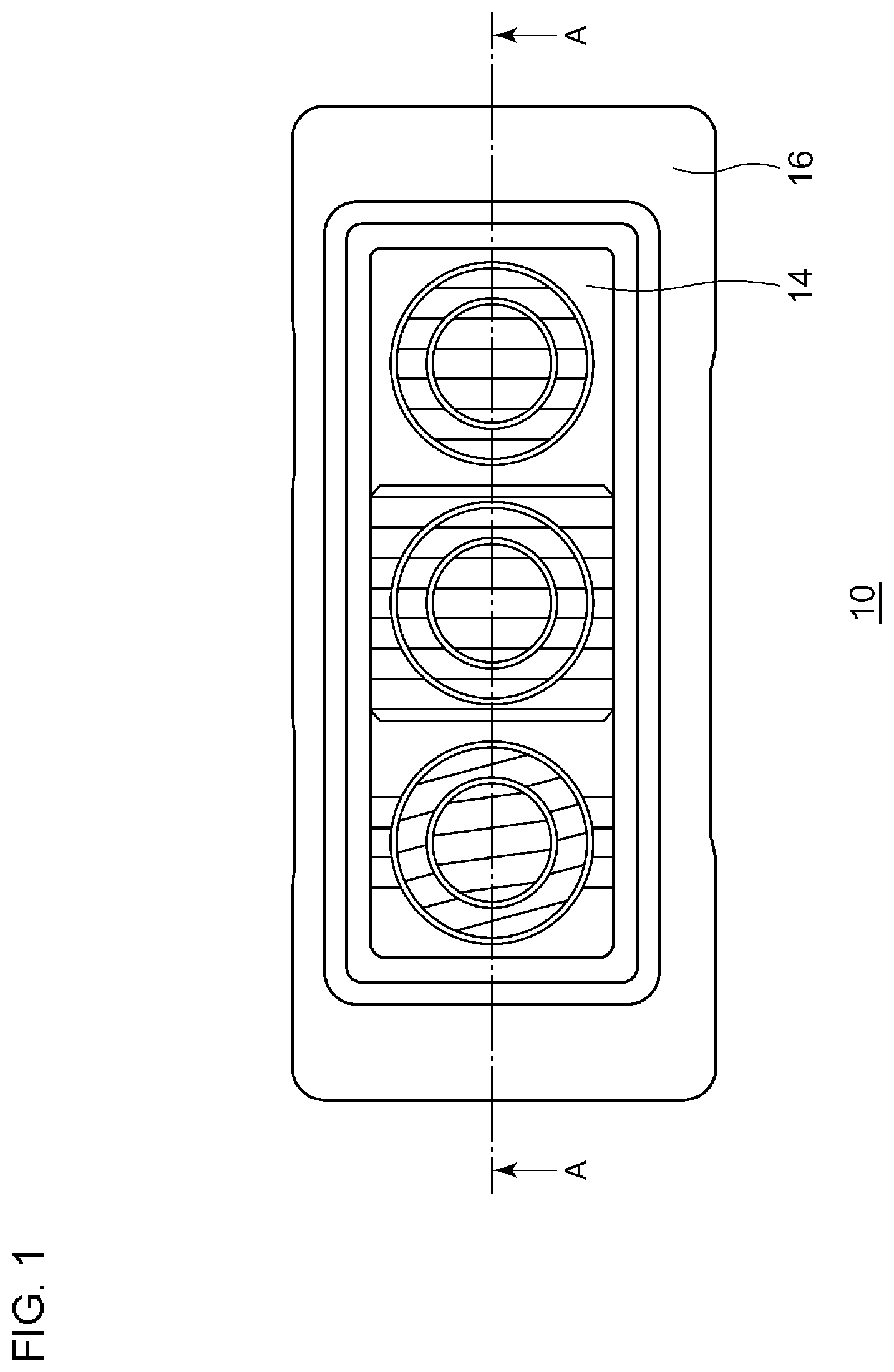
is a front view of a vehicle lamp according to a first embodiment;
is an exploded perspective view of the vehicle lamp according to the first embodiment;
is a sectional view of the vehicle lamp illustrated in , taken along the A-A line;
is a schematic diagram for describing a method of manufacturing the vehicle lamp according to the first embodiment;
is a perspective view, viewed from the above, of a light emitting module according to the first embodiment;
is a rear view of the light emitting module according to the first embodiment;
is an enlarged view of the vicinity of an opening in the light emitting module illustrated in ;
is a schematic diagram of one section including the opening in the light emitting module according to the first embodiment;
is a perspective view, viewed from the above, of a light emitting module according to a second embodiment;
is a rear view of the light emitting module according to the second embodiment;
is an enlarged view of the vicinity of an opening in the light emitting module illustrated in ;
A and 12 B are each an enlarged view of the vicinity of a portion connecting a wiring board and a circuit board in the light emitting module according to the second embodiment;
A is a front view of a vehicle lamp according to a third embodiment, and B is a perspective view of the vehicle lamp according to the third embodiment; and
is an exploded perspective view of the vehicle lamp according to the third embodiment.
DETAILED DESCRIPTION
Outline of Embodiments
A vehicle lamp according to one aspect of the present disclosure includes a substrate having a light source mounted thereon, a lens that light emitted from the light source enters and passes through to exit forward, and a holder that holds the lens. The substrate and the lens are positioned to the holder.
According to this aspect, the substrate and the lens are positioned to the holder, the common member, and thus the accuracy of positioning the substrate and the lens improves.
The lens may be provided within a region on one side of an opening in the holder where the substrate is located; and the lens may include a center portion that refracts the light from the light source to allow the light to exit forward, and an outer edge portion surrounding the center portion, the outer edge portion being to internally reflect the light emitted from the light source and having entered the outer edge portion to allow the light to exit forward. With this configuration, the lens does not protrude from the holder, as a convex lens does, and thus the thickness of the vehicle lamp in the front-back direction of the vehicle can be reduced.
The holder may include a flange portion surrounding the opening. The lens may be secured to a positioning portion provided on an inner side of the flange portion. This configuration allows the lens to be mounted from the back side of the holder to be positioned.
The substrate may be a metal plate having a thickness of 1-2 mm, and the metal plate may be exposed on one surface thereof opposite a surface on which the light source is mounted. This configuration can reduce the thickness of the vehicle lamp in the front-back direction of the vehicle.
Another aspect of the present disclosure provides a method of manufacturing a vehicle lamp. This method includes preparing a tubular holder having an opening that allows light from a light source to exit therethrough; positioning a lens to a positioning portion so formed on an inner side of the opening as to surround the opening; and positioning a substrate having the light source mounted thereon to a securing portion opposite the opening in the holder. The positioning of the lens and the positioning of the substrate are performed through welding by laser emitted from the same side.
According to this aspect, the positioning of the lens and the positioning of the substrate can be achieved through welding by laser emitted from the same side, and this can reduce the necessity for changing the orientation of a laser welding apparatus or for rotating components, such as the lens or the holder, during the manufacture.
Hereinafter, some embodiments for implementing the present invention will be described in detail with reference to the drawings. In the description of the drawings, identical elements are given identical reference characters, and duplicate description thereof will be omitted, as appropriate. The configurations described below are illustrative in nature and do not in any way limit the scope of the present invention.
First Embodiment
[Vehicle Lamp]
is a front view of a vehicle lamp according to a first embodiment. is an exploded perspective view of the vehicle lamp according to the first embodiment. is a sectional view of the vehicle lamp illustrated in , taken along the A-A line.
A vehicle lamp 10 includes a light emitting module 12 , a lens 14 , and a holder 16 . The light emitting module 12 includes a metal plate 18 and three semiconductor light emitting elements (light emitting diodes 20 ). The metal plate 18 is a plate-like member made of aluminum, copper, or the like. Each of the three semiconductor light emitting elements is mounted on the metal plate 18 and serves as a light source. The semiconductor light emitting elements may be laser elements or EL elements. The lens 14 includes three optical control regions R 1 to R 3 , which control respective optical paths such that light L emitted from the light emitting diodes 20 enters and passes through the lens 14 to exit forward. The holder 16 holds the lens 14 with the lens 14 positioned to the holder 16 . The metal plate 18 is secured to the holder 16 by three screws 19 with the metal plate 18 positioned to the holder 16 .
In this manner, in the vehicle lamp 10 according to the present embodiment, the metal plate 18 and the lens 14 are positioned to the holder 16 , the common member, and thus the accuracy of positioning the metal plate 18 and the lens 14 improves. As the accuracy of relative positioning of the metal plate 18 and the lens 14 improves, a desired light distribution pattern to be projected ahead of the vehicle can be formed with high accuracy.
The lens 14 does not protrude forward from an opening 16 a in the holder 16 , and the entirety of the lens 14 is contained within a space on the side of the opening 16 a where the metal plate 18 is located. In other words, the entirety of the lens 14 is contained in a region defined by the holder 16 and the metal plate 18 . Each of the optical control regions R 1 to R 3 of the lens 14 includes a center portion 14 a and an outer edge portion 14 b . The center portions 14 a refract light L from their corresponding light emitting diodes 20 to allow the light L to exit forward. The outer edge portions 14 b surround the respective center portions 14 a . The outer edge portions 14 b internally reflect light L emitted from the corresponding light emitting diodes 20 and having entered the outer edge portions 14 b to allow the light L to exit forward. With this configuration, even though the lens 14 is not so shaped as to protrude from the holder, as a convex lens is, a desired light distribution pattern can be formed, and the thickness of the vehicle lamp 10 in the front-back direction of the vehicle can be reduced.
Next, positioning of the components of the vehicle lamp 10 according to the present embodiment will be described. The holder 16 includes a flange portion 16 b surrounding the opening 16 a . The lens 14 is secured to a positioning portion 16 c provided on an inner side of the flange portion 16 b . This configuration allows the lens 14 to be mounted from the back side of the holder 16 to be positioned.
The metal plate 18 includes positioning holes 18 a , and positioning protrusions 16 e provided on a back-side end surface 16 d of the holder 16 are inserted into the respective positioning holes 18 a . As the protrusions 16 e are fitted into the respective positioning holes 18 a , the metal plate 18 is positioned to the holder 16 .
The metal plate 18 has a thickness of 1-2 mm, and its surface is blackened through anodization, painting, or the like, which improves the rate of heat dissipation from the metal plate 18 . Then, owning to a combination of a feature that a surface 18 c opposite a mounting surface 18 b on which the light emitting diodes 20 are mounted is exposed to the outside, the improved rate of heat dissipation from the metal plate 18 , a feature that the plurality of light emitting diodes 20 are disposed discretely with a space therebetween, and so on, the light emitting module 12 can satisfy a desired heat dissipation performance without the need for a heat sink for mounting the metal plate 18 . Thus, the thickness of the vehicle lamp 10 in the front-back direction of the vehicle can be reduced.
is a schematic diagram for describing a method of manufacturing a vehicle lamp according to the first embodiment. is an exploded view of the vehicle lamp, viewed from its side.
As illustrated in , the manufacturing method according to the present embodiment includes a preparation step of preparing the tubular holder 16 having the opening 16 a , which allows light from the light emitting diodes 20 to exit therethrough; a lens positioning step of positioning a front end surface 14 c of the lens 14 to the positioning portion 16 c so formed on an inner side (the side closer to the substrate) of the opening 16 a as to surround the opening 16 a ; and a substrate positioning step of positioning the metal plate 18 having the light emitting diodes 20 mounted thereon to securing portions (the protrusions 16 e on the back-side end surface 16 d ) opposite the opening 16 a in the holder 16 .
In the lens positioning step and the substrate positioning step, the lens 14 and the metal plate 18 can be mounted to the holder 16 from the same direction. The lens 14 is welded and secured to the holder 16 by making the front end surface 14 c abut the positioning portion 16 c of the holder 16 and, in that state, by irradiating the abutted region with laser from the back side of the lens 14 . The metal plate 18 is welded and secured to the holder 16 by making the metal plate 18 abut the back-side end surface 16 d of the holder 16 and, with the protrusions 16 e fitted in the respective positioning holes 18 a , by irradiating the vicinity of each protrusion 16 e protruding into the rear side of the metal plate 18 with laser from the back side. Alternatively, the metal plate 18 is welded and secured to the holder 16 by inserting the protrusions 16 e into the respective positioning holes 18 a for positioning and then by tightening them with screws or the like with use of other holes provided for securing.
According to this aspect, the lens positioning step and the substrate positioning step can be achieved through welding with use of laser emitted from the same side, and this can reduce the necessity for changing the orientation of a laser welding apparatus or for rotating components, such as the lens or the holder, during the manufacture. Furthermore, the portion where the lens 14 is welded to the holder 16 comes on the inner side (the rear side) of the flange portion 16 b , and thus the welded portion is not visible from the front of the vehicle lamp 10 , which leads to a better outer appearance. Light that passes through the welded portion is blocked by the flange portion 16 b , and thus any uncontrolled light, such as glare, that leaks to the outside can be reduced. Alternatively, the mounting work can be done from the same side when the screws or the like are tightened. Thus, the workability improves, and an occurrence of any defect that would be caused by a mounting error can be suppressed.
[Light Emitting Module]
Next, a preferred embodiment of a light emitting module will be described. is a perspective view, viewed from the above, of the light emitting module according to the first embodiment. is a rear view of the light emitting module according to the first embodiment. is an enlarged view of the vicinity of an opening in the light emitting module illustrated in . is a schematic diagram of one section including the opening in the light emitting module according to the first embodiment.
The light emitting module 12 includes the three light emitting diodes 20 , a circuit board 24 provided with a lighting control circuit 22 that controls on/off of the light emitting diodes 20 and a connector 23 to be connected to an outside connector, and the metal plate 18 serving as an element metal plate on which the light emitting diodes 20 are mounted. The circuit board 24 is a multilayer resin substrate having a wiring portion 26 formed therein for connecting the light emitting diodes 20 and the lighting control circuit 22 . This configuration allows the lighting control circuit 22 and the light emitting diodes 20 to be connected with a simple configuration, as illustrated in . The lighting control circuit 22 is so configured as to include passive elements (e.g., resistance, coil, capacitor, etc.) necessary for driving the light emitting diodes 20 and active elements (e.g., transistor, IC, diode, operational amplifier, etc.).
The circuit board 24 according to the present embodiment is a multilayer substrate having the wiring portion 26 inside and in its surface layer. For example, the circuit board 24 is a glass epoxy substrate having a copper foil pattern that serves as a wiring portion formed on the surface or inside the substrate. This configuration can lower the cost, as compared with one that is thick and requires high material and manufacturing cost, such as a power feed attachment with a built-in busbar. The circuit board may be formed of a phenolic resin or a polyimide resin. The portion of the wiring portion 26 that is exposed in an opening 24 b is subjected to metal surface treatment (nickel plating treatment, gold plating treatment, or the like). This improves the bonding performance of a metal wire 28 , such as a gold wire, an aluminum wire, or an aluminum ribbon. The rear-side surface layer of the circuit board 24 that comes into contact with the metal plate 18 is formed solely of an insulating material. With this configuration, not only an insulating adhesive with a high heat dissipation performance but also a conductive adhesive can be used to bond the circuit board 24 to the conductive metal plate 18 .
As illustrated in , at least a portion of the circuit board 24 is mounted on the metal plate 18 , and the wiring portion 26 is formed between the lighting control circuit 22 and the metal plate 18 in the thickness direction of the substrate. The lighting control circuit 22 is mounted on a surface 24 a of the circuit board 24 . With this configuration, heat produced by the components (e.g., IC) used in the lighting control circuit 22 travels not only in the thickness direction but also in the horizontal direction via the wiring portion 26 in the circuit board 24 , which leads to improved heat dissipation performance.
The light emitting diodes 20 are disposed in the respective openings 24 b formed in the circuit board 24 . This configuration allows the light emitting diodes 20 to be mounted directly on the metal plate 18 . The plurality of openings 24 b are provided with a space therebetween, and the light emitting diodes 20 are disposed in the respective openings 24 b . The optical control regions R 1 to R 3 of the lens 14 correspond to the respective light emitting diodes 20 . This configuration allows a plurality of light sources of different light distributions to be provided in a single light emitting module.
Each light emitting diode 20 is connected to the wiring portion 26 via the metal wire 28 . This configuration can improve the reliability of the connection between the wiring portion 26 and an electrode pad 20 a of each light emitting diode 20 . Furthermore, the use of the metal wire 28 can reduce the area of each electrode pad 20 a . The electrode pad 20 a according to the present embodiment has an area smaller than that of a light emitting surface 20 b of each light emitting diode 20 . When the light emitting surfaces 20 b of the light emitting diodes 20 face ahead of the vehicle, thin metal wires 28 or small electrode pads 20 a are less noticeable when the vehicle lamp 10 is viewed from the front.
As illustrated in , the light emitting module 12 further includes a circuit metal plate 30 separate from the metal plate 18 . The circuit board 24 is mounted over the metal plate 18 and the circuit metal plate 30 , and the metal plate 18 and the circuit metal plate 30 are thermally isolated from each other. With this configuration, the shape or the size of the metal plate 18 serving as an element metal plate can be set in consideration of heat produced by the light emitting diodes 20 , and the shape or the size of the circuit metal plate 30 can be set in consideration of heat produced in the lighting control circuit 22 . Thus, the configuration flexibility improves.
The metal plate 18 is a single-piece plate-like member and has a rectangular cut-out portion 18 e formed in an outer peripheral portion 18 d , and the rectangular circuit metal plate 30 fits in the cut-out portion 18 e . The metal plate 18 and the circuit metal plate 30 fitted in the cut-out portion 18 e together form a rectangular shape. This configuration allows the two metal plates together to make a simple rectangular shape, and thus interference or competing for space among members can be reduced, and the layout flexibility increases in turn.
The metal plate 18 or the circuit metal plate 30 is a metal plate having a thickness of 1-2 mm and made of aluminum, copper, or the like. Thus, the light emitting module 12 can be made thinner. As illustrated in , the lighting control circuit 22 that includes an element, such as an IC, with relatively large heat production is provided at a position away from, of the three light emitting diodes 20 , the center light emitting diode 20 A with a relatively low heat dissipation performance. This can mitigate an influence of heat produced by the lighting control circuit 22 on the light emitting diode 20 A. As illustrated in or 3 , the region defined by the lens 14 , the metal plate 18 , and the holder 16 includes a certain dead space, and the components constituting the lighting control circuit 22 are disposed in this dead space. This configuration can suppress any increase, attributable to the lighting control circuit 22 , in the thickness of the vehicle lamp 10 in the front-back direction of the vehicle.
Second Embodiment
is a perspective view, viewed from the above, of a light emitting module according to a second embodiment. is a rear view of the light emitting module according to the second embodiment. is an enlarged view of the vicinity of an opening in the light emitting module illustrated in . A and 12 B are each an enlarged view of the vicinity of a portion connecting a wiring board and a circuit board in the light emitting module according to the second embodiment.
A light emitting module 32 includes three light emitting diodes 20 , a metal plate 18 serving as an element metal plate on which the light emitting diodes 20 are mounted, a wiring board 34 disposed on the metal plate 18 , and a circuit board 36 provided with a lighting control circuit (not illustrated) that controls on/off of the light emitting diodes 20 . The wiring board 34 includes openings 34 a for mounting the light emitting diodes 20 onto the metal plate 18 . A portion 38 a of a wire (busbar) 38 inside the wiring board 34 is exposed through the corresponding opening 34 a , and each opening 34 a has a depth that allows the opening 34 a to surround a metal wire 28 serving as a connecting member connecting the corresponding light emitting diode 20 and the exposed portion 38 a of the wire 38 .
This configuration allows the lighting control circuit and the light emitting diodes 20 to be connected with a simple configuration. Furthermore, since each opening 34 a has a depth D (see ) that allows the opening 34 a to surround the metal wire 28 , the metal wire 28 is less likely to come into contact with other components.
Each opening 34 a is configured not to allow the metal wire 28 to protrude from the surface of the wiring board 34 . This configuration prevents the metal wire 28 from coming into contact with other members that the metal wire 28 should not come into contact with, and, for example, renders is unnecessary to cover the metal wire 28 with an insulating protective resin. As a result, the cost of the light emitting module 32 can be reduced.
The wiring board 34 is a resin substrate integrated with the metal plate 18 and a metal busbar. The openings 34 a are recess portions that house the respective light emitting diodes 20 , and a portion of the busbar is exposed through a side wall of the recess portions. This configuration allows the metal wire 28 to be connected to the portion of the busbar without protruding from the surface of the wiring board 34 . The wiring board 34 includes an exterior unit or a housing formed of engineering plastics and the busbar provided in the exterior unit or the housing. This configuration, however, is not a limiting example, and the wiring board 34 may be a multilayer resin substrate having a copper foil pattern serving as a wire buried therein.
As illustrated in A , the wiring board 34 and the circuit board 36 are connected to each other as an end portion of the busbar serving as the wire 38 is connected, with a metal jumper wire 42 , to an end portion of a copper foil pattern serving as a wire 40 of the circuit board 36 . Alternatively, as illustrated in B , an end portion of the wire 38 may be so formed as to extend over the wire 40 of the circuit board 36 , and the wire 38 may urge the wire 40 with its elasticity. The wiring board 34 and the circuit board 36 may be a common, single-piece substrate. Such a configuration can reduce the number of substrates, and the cost of components, such as a jumper wire, connecting substrates or the assembly work can be reduced.
Third Embodiment
A is a front view of a vehicle lamp according to a third embodiment, and B is a perspective view of the vehicle lamp according to the third embodiment. is an exploded perspective view of the vehicle lamp according to the third embodiment. Components similar to those of the vehicle lamp 10 according to the first embodiment are given identical reference characters, and descriptions thereof will be omitted, as appropriate.
A vehicle lamp 110 includes a light emitting module 112 , a lens 114 , and a holder 116 . The light emitting module 112 includes a metal plate 118 and three semiconductor light emitting elements (light emitting diodes 20 ). The metal plate 118 is a plate-like member made of aluminum, copper, or the like. Each of the three semiconductor light emitting elements is mounted on the metal plate 118 and serves as a light source. The three light emitting diodes 20 are disposed at the respective vertices of a triangle (right triangle or isosceles triangle).
The lens 114 includes three optical control regions R 4 to R 6 , which control respective optical paths such that light L emitted from the light emitting diodes 20 enters and passes through the lens 114 to exit forward. The optical control regions R 4 to R 6 are so provided as to form a triangle ahead of the three light emitting diodes 20 .
Thus far, the present invention has been described with reference to the foregoing embodiments. The present invention, however, is not limited to the foregoing embodiments, and the present invention also encompasses an embodiment obtained by combining and/or replacing components, as appropriate, of the foregoing embodiments. It is also possible to change the combinations or the order of processes in the foregoing embodiments or to add modifications, such as various design changes, to the foregoing embodiments on the basis of the knowledge of a person skilled in the art, and an embodiment obtained by adding such modifications may also be encompassed by the scope of the present invention.
Figures (9)
Citations
This patent cites (28)
- US11168848
- US20070206369
- US20090154185
- US20120243250
- US20130250599
- US20160290587
- US20170356628
- US20180106445
- US20180156408
- US20190338930
- US20190351817
- US20190353320
- US20200116323
- US20200149701
- US20210231286
- US101457889
- US102345823
- US102798067
- US107208861
- US107636386
- US111076137
- US211203922
- US102014104503
- US2009146665
- US2016139514
- US2017139354
- US2019204615
- US2018158867