Abstract
The combustor for a rocket engine includes a combustion room configured to cause a combustion reaction between a fuel and an oxidant, an injector configured to inject the fuel and the oxidant into the combustion room, and a nozzle skirt configured to inject combustion gas generated by the combustion reaction to an outside, and an inertance increasing portion configured to increase an equivalent inertance in a vibration equivalent circuit of the combustor for the rocket engine.
Claims (5)
1. A combustor for a rocket engine comprising: a combustion room configured to cause a combustion reaction between a fuel and an oxidant, the combustion room being an internal space of a combustion chamber; an injector configured to inject the fuel and the oxidant into the combustion room; a nozzle skirt configured to inject combustion gas generated by the combustion reaction to an outside; an inertance increasing portion configured to increase an equivalent inertance in a vibration equivalent circuit of the combustor for the rocket engine; a fuel passage configured to guide the fuel to the combustion room, the fuel passage including a plurality of fuel branch pipes and a fuel branch portion including a tournament-type branch form in which a plurality of fuel branch flow paths each of which branching a fuel flow path into two fuel flow paths is sequentially repeated to be arranged in a flow direction of the fuel and configured to distribute the fuel to the plurality of fuel branch pipes; and an oxidant passage configured to guide the oxidant to the combustion room, the oxidant passage including a plurality of oxidant branch pipes and an oxidant branch portion including a tournament-type branch form in which a plurality of oxidant branch flow paths each of which branching an oxidant flow path into two oxidant flow paths are sequentially repeated to be arranged and configured to distribute the oxidant to the plurality of oxidant branch pipes, wherein the inertance increasing portion increases the equivalent inertance by providing the fuel branch portion, the oxidant branch portion, the plurality of fuel branch pipes, and the plurality of oxidant branch pipes in the fuel passage and the oxidant passage to lengthen a passage length thereof, and wherein the plurality of fuel branch pipes and the plurality of oxidant branch pipes are provided on a wall surface of the combustion chamber and the nozzle skirt to be adjacent to each other.
Show 4 dependent claims
2. The combustor for the rocket engine according to claim 1 , wherein the inertance increasing portion branches the fuel passage and the oxidant passage without changing a passage cross-sectional area in front of and behind the fuel branch portion and the oxidant branch portion.
3. The combustor for the rocket engine according to claim 1 , wherein the plurality of fuel branch pipes in the fuel passage and the plurality of oxidant branch pipes in the oxidant passage are provided from a base end to an end portion of the nozzle skirt and is folded back at the end portion.
4. The combustor for the rocket engine according to claim 3 , wherein the plurality of fuel branch pipes in the fuel passage and the plurality of oxidant branch pipes in the oxidant passage are spirally provided with respect to the nozzle skirt.
5. The combustor for the rocket engine according to claim 1 , wherein the plurality of fuel branch pipes in the fuel passage and the plurality of oxidant branch pipes in the oxidant passage are spirally provided with respect to the nozzle skirt.
Full Description
Show full text →
This application is a Continuation Application based on International Application No. PCT/JP2021/004584, filed on Feb. 8, 2021, which claims priority on Japanese Patent Application No. 2020-033320, filed on Feb. 28, 2020, the contents of which are incorporated herein by reference.
TECHNICAL FIELD
The present disclosure relates to a combustor for a rocket engine.
BACKGROUND ART
The following Patent Document 1 discloses a thrust control apparatus and a thrust control method for a liquid rocket engine. The purpose of the thrust control apparatus and thrust control method is to reduce the possibility of generating low-frequency combustion vibration (chugging) caused by an extreme decrease in injection differential pressure (a difference between an injection pressure and a combustion pressure) when operating in a reduced thrust range by controlling a thrust to be reduced in the thrust control of a rocket engine. According to the thrust control apparatus and thrust control method, in a liquid rocket engine that injects a liquid propellant into a combustion room through an injection orifice, a temperature control means for controlling the temperature of the liquid propellant at an upstream side of the injection orifice is provided and the temperature of the liquid propellant is raised so as to secure an injection differential pressure needed for reduction control using a saturated vapor pressure of the liquid propellant when controlling the thrust of the engine to be reduced.
CITATION LIST
Patent Document
Patent Document 1
•
• Japanese Unexamined Patent Application, First Publication No. 2013-155655
SUMMARY OF THE INVENTION
Technical Problem
From the viewpoint of suppressing vibration of a combustor for a rocket engine, in a liquid rocket engine described in Patent Document 1, vibration can be suppressed in a single thrust (operating point) by changing a shape of an injection orifice, but vibration cannot be suppressed in a plurality of thrusts. For example, unlike a disposable type, a combustor for a reusable rocket engine is used in a relatively wide thrust range for a landing operation and the like. Therefore, in the liquid rocket engine described in Patent Document 1, the vibration of the combustor for the reusable rocket engine cannot be effectively suppressed over an entire thrust range.
The present disclosure has been made in view of the above circumstances, and an object of the present disclosure is to provide a combustor for a rocket engine capable of effectively suppressing vibration when operating with a plurality of thrusts.
Solution to Problem
A combustor for a rocket engine according to a first aspect of the present disclosure includes a combustion room configured to cause a combustion reaction between a fuel and an oxidant, an injector configured to inject the fuel and the oxidant into the combustion room, a nozzle skirt configured to inject combustion gas generated by the combustion reaction to an outside, and an inertance increasing portion configured to increase an equivalent inertance in a vibration equivalent circuit of the combustor for the rocket engine.
The combustor for the rocket engine according to a second aspect of the present disclosure may further include, in the first aspect described above, a fuel passage configured to guide the fuel to the combustion room, and an oxidant passage configured to guide the oxidant to the combustion room, in which the inertance increasing portion increases the equivalent inertance by providing a plurality of branch portions in the fuel passage or/and the oxidant passage to lengthen a passage length thereof.
In the combustor for the rocket engine according to a third aspect of the present disclosure, in the second aspect described above, the inertance increasing portion may branch the fuel passage or/and the oxidant passage without changing a passage cross-sectional area in front of and behind the branch portion.
In the combustor for the rocket engine according to a fourth aspect of the present disclosure, in the second or third aspect described above, the fuel passage or/and the oxidant passage may include a cooling passage configured to cool the nozzle skirt, and in the inertance increasing portion, the plurality of branch portions are provided in front of the cooling passage.
In the combustor for the rocket engine according to a fifth aspect of the present disclosure, in the fourth aspect described above, the cooling passage may be provided from a base end to an end portion of the nozzle skirt and folded back at the end portion.
In the combustor for the rocket engine according to a sixth aspect of the present disclosure, in the fourth or fifth aspect described above, the cooling passage may be spirally provided with respect to the nozzle skirt.
According to the present disclosure, it is possible to provide a combustor for a rocket engine capable of effectively suppressing vibration when operating with a plurality of thrusts.
BRIEF DESCRIPTION OF DRAWINGS
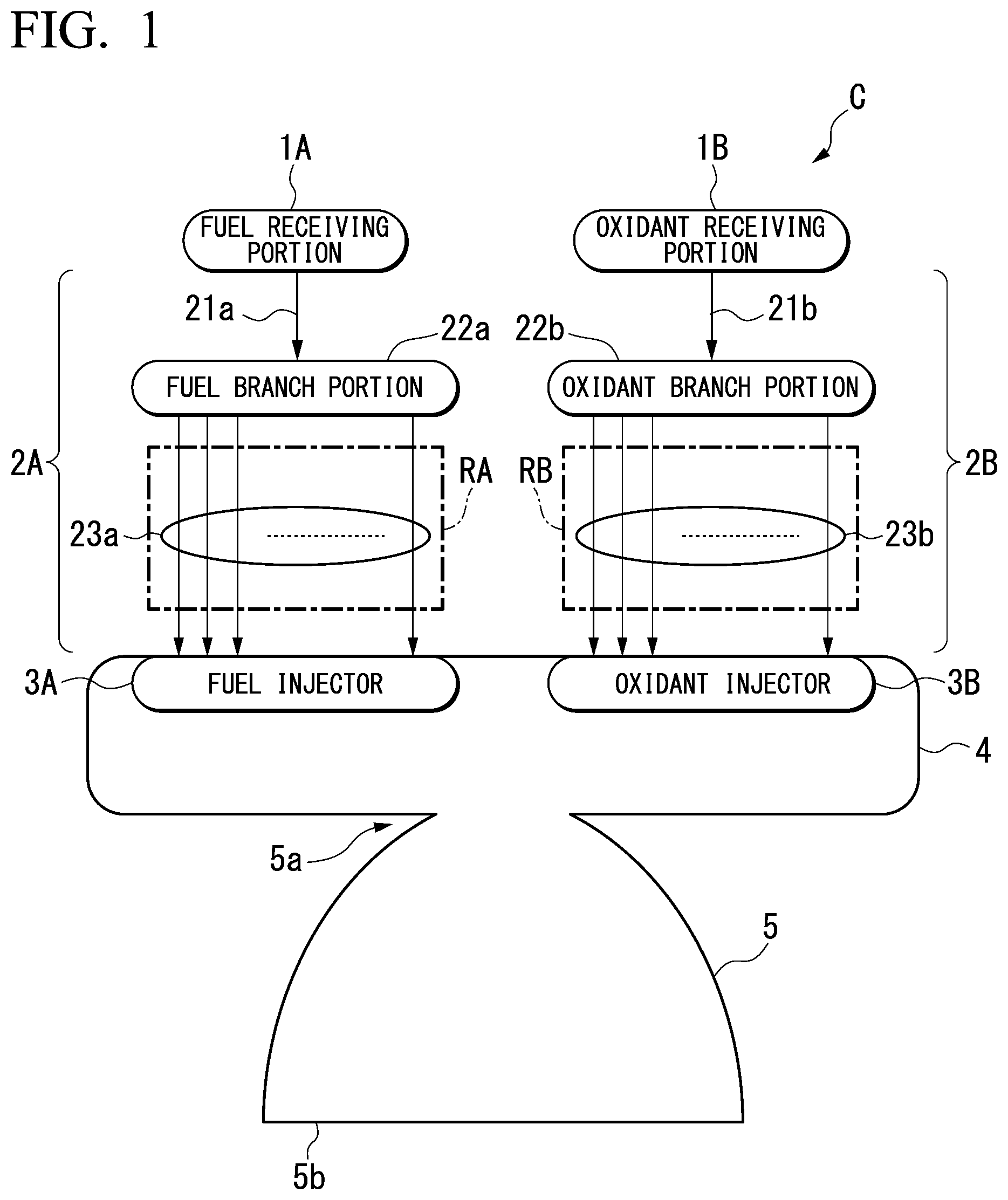
is a schematic diagram showing a configuration of a combustor for a rocket engine according to an embodiment of the present disclosure.
is a schematic diagram showing details of a fuel branch portion and an oxidant branch portion in an embodiment of the present disclosure.
A is a view showing an arrangement of branch pipes in an embodiment of the present disclosure.
B is a partially enlarged view of branch pipes in an embodiment of the present disclosure.
is a vibration equivalent circuit of a combustor for a rocket engine according to an embodiment of the present disclosure.
DETAILED DESCRIPTION OF THE EMBODIMENTS
Hereinafter, an embodiment of the present disclosure will be described with reference to the drawings.
A combustor C for a rocket engine according to the present embodiment is a combustor constituting a reusable rocket engine. That is, unlike a combustor for a disposable rocket in the related art, the combustor C for the rocket engine is a combustor that operates with a plurality of thrusts (operating points) in a wide range, that is, operates even with a thrust (low operating point) that is significantly lower than a normal thrust, in addition to the normal thrust (normal operating point).
As shown in , the combustor C for the rocket engine includes a fuel receiving portion 1 A, an oxidant receiving portion 1 B, a fuel passage 2 A, an oxidant passage 2 B, a fuel injector 3 A, an oxidant injector 3 B, a combustion chamber 4 , and a nozzle skirt 5 . Furthermore, the fuel passage 2 A and the oxidant passage 2 B in the present embodiment correspond to an inertance increasing portion of the present disclosure.
The fuel receiving portion 1 A is a receiving port that receives a fuel from a fuel supply system. That is, the fuel receiving portion 1 A is a receiving port that receives a liquid fuel at a predetermined pressure from the fuel supply system configured with a fuel tank, a fuel pump, and the like, and supplies the liquid fuel to the fuel passage 2 A. The liquid fuel is, for example, liquid hydrogen or liquefied natural gas.
The oxidant receiving portion 1 B is a receiving port for receiving an oxidant from an oxidant supply system. That is, the oxidant receiving portion 1 B is a receiving port that receives an oxidant at a predetermined pressure from the oxidant supply system configured with an oxidant tank, an oxidant pump, and the like, and supplies the oxidant to the oxidant passage 2 B. The oxidant is, for example, liquid oxygen.
The fuel passage 2 A is a metal pipe that guides the liquid fuel supplied from the fuel supply system to the fuel injector 3 A via the fuel receiving portion 1 A. The fuel passage 2 A includes a receiving pipe 21 a , a fuel branch portion 22 a , and a plurality of branch pipes 23 a . The receiving pipe 21 a is a single pipe connecting the fuel receiving portion 1 A and the fuel branch portion 22 a to each other to circulate the liquid fuel from the fuel receiving portion 1 A to the fuel branch portion 22 a.
The fuel branch portion 22 a is an aggregate of a plurality of branch portions S as shown in . That is, the fuel branch portion 22 a , that is, the plurality of branch portions S in the fuel passage 2 A, is to lengthen a pipe length (passage length) of the fuel passage 2 A by sequentially branching the receiving pipe 21 a (single passage), which is a single pipe. In addition, by branching the passage, an effect of creating a fine shower of liquid fuel suitable for combustion can be expected.
Here, a passage branching method in which a single passage is branched into a plurality of passages with a single branch portion S may be employed, but in the present embodiment as will be described later, an equivalent inertance L in a vibration equivalent circuit is increased by lengthening the pipe length (passage length) of the fuel passage 2 A. Therefore, the fuel branch portion 22 a employs a tournament-type branch form that increases the pipe length (passage length) of the fuel passage 2 A, for example, by providing the plurality of branch portions S, and sequentially repeating branching into two passages at each branch portion S as shown in , without branching the passage into the plurality of passages at one location.
The fuel branch portion 22 a distributes the liquid fuel flowing in from the receiving pipe 21 a to the plurality of branch pipes 23 a . The plurality of branch pipes 23 a are pipes connected to the fuel branch portion 22 a via the plurality of branch portions S. These branch pipes 23 a guide the liquid fuel flowing in from the fuel branch portion 22 a to the fuel injector 3 A.
In addition, these branch pipes 23 a constitute a cooling passage RA as shown in . The cooling passage RA is a pipe portion that contributes to cooling the combustion chamber 4 and the nozzle skirt 5 . That is, the cooling passage RA (plurality of branch pipes 23 a ) is mechanically provided densely on a wall surface of the combustion chamber 4 and the nozzle skirt 5 so as to be adjacent to each other as shown in A and 3 B to cool the combustion chamber 4 and the nozzle skirt 5 by the liquid fuel circulating therein.
These branch pipes 23 a are provided over an entire wall surface of the combustion chamber 4 , and on a wall surface of the nozzle skirt 5 from a base end 5 a (upper end) to an end portion 5 b (lower end) as shown in A . That is, these branch pipes 23 a are provided over an entire surface of the combustion chamber 4 and the nozzle skirt 5 .
In addition, these branch pipes 23 a are spirally provided with respect to wall surfaces of the combustion chamber 4 and the nozzle skirt 5 and are folded back at the end portion 5 b of the nozzle skirt 5 , and the branch pipes 23 a adjacent to each other are provided such that flow directions of the liquid fuel are opposite to each other as shown in B . That is, the plurality of branch pipes 23 a are provided such that the liquid fuel flows in a spiral and reciprocating manner from an upper end of the combustion chamber 4 to the end portion 5 b (lower end) of the nozzle skirt 5 . Furthermore, the branch pipes 23 a may not have a spiral shape as long as the required passage length of the fuel passage 2 A can be obtained.
Here, a total cross-sectional area of the plurality of branch pipes 23 a is equal to a cross-sectional area of the single receiving pipe 21 a . That is, the fuel branch portion 22 a (branch portion S) branches the fuel passage 2 A without changing the passage cross-sectional area in front and behind.
In the fuel passage 2 A configured in this manner, in addition to lengthening the pipe length (passage length) of the fuel passage 2 A by the fuel branch portion 22 a , the pipe length (passage length) of the fuel passage 2 A is also lengthened by the plurality of branch pipes 23 a . In the foregoing fuel passage 2 A, since the passage length of the fuel passage through which the liquid fuel circulates is longer than that of a combustor for a rocket engine in the related art, the equivalent inertance L in the vibration equivalent circuit can be sufficiently increased.
The oxidant passage 2 B is a metal pipe that guides the oxidant supplied from the oxidant supply system to the oxidant injector 3 B via the oxidant receiving portion 1 B. The oxidant passage 2 B includes a receiving pipe 21 b , an oxidant branch portion 22 b , and a plurality of branch pipes 23 b . The receiving pipe 21 b is a single pipe connecting the oxidant receiving portion 1 B and the oxidant branch portion 22 b to each other to circulate the oxidant from the oxidant receiving portion 1 B to the oxidant branch portion 22 b.
The oxidant branch portion 22 b is an aggregate of a plurality of branch portions S as shown in . The oxidant branch portion 22 b , that is, the plurality of branch portions S in the oxidant passage 2 B, is to lengthen a pipe length (passage length) of the oxidant passage 2 B by sequentially branching the receiving pipe 21 b (single passage), which is a single pipe.
As described above, in the present embodiment, an equivalent inertance is increased by lengthening the pipe length (passage length) of the oxidant passage 2 B. Therefore, the oxidant branch portion 22 b employs a branch form that increases the pipe length (passage length) of the oxidant passage 2 B by providing the plurality of branch portions S, and sequentially repeating branching into two passages at each branch portion S as shown in , without branching the passage into the plurality of passages at one location.
The oxidant branch portion 22 b distributes the oxidant flowing in from the receiving pipe 21 b to the plurality of branch pipes 23 b . The plurality of branch pipes 23 b are pipes connected to the oxidant branch portion 22 b via the plurality of branch portions S. These branch pipes 23 b guide the oxidant flowing in from the oxidant branch portion 22 b to the oxidant injector 3 B.
In addition, these branch pipes 23 b constitute a cooling passage RB as shown in . Similar to the cooling passage RA, the cooling passage RB is a pipe portion that contributes to cooling the combustion chamber 4 and the nozzle skirt 5 . That is, the cooling passage RB (plurality of branch pipes 23 b ) is mechanically provided densely on a wall surface of the combustion chamber 4 and the nozzle skirt 5 so as to be adjacent to each other to cool the combustion chamber 4 and the nozzle skirt 5 by the oxidant circulating therein.
Similar to the branch pipes 23 a of the fuel passage 2 A, these branch pipes 23 b are provided over an entire wall surface of the combustion chamber 4 , and on a wall surface of the nozzle skirt 5 from a base end 5 a (upper end) to an end portion 5 b (lower end). That is, these branch pipes 23 b are provided over an entire surface of the combustion chamber 4 and the nozzle skirt 5 .
In addition, similar to the branch pipes 23 a of the fuel passage 2 A, these branch pipes 23 b are spirally provided with respect to wall surfaces of the combustion chamber 4 and the nozzle skirt 5 and are folded back at the end portion 5 b of the nozzle skirt 5 , and the branch pipes 23 b adjacent to each other are provided such that flow directions of the oxidant are opposite to each other as shown in B . That is, the plurality of branch pipes 23 b are provided such that the oxidant flows in a spiral and reciprocating manner from an upper end of the combustion chamber 4 to the end portion 5 b (lower end) of the nozzle skirt 5 .
Here, a total cross-sectional area of the plurality of branch pipes 23 b is equal to a cross-sectional area of the single receiving pipe 21 b . That is, the oxidant branch portion 22 b (branch portion S) branches the oxidant passage 2 B without changing the passage cross-sectional area in front and behind.
In the oxidant passage 2 B configured in this manner, in addition to lengthening the pipe length (passage length) of the oxidant passage 2 B by the oxidant branch portion 22 b , the pipe length (passage length) of the oxidant passage 2 B is also lengthened by the plurality of branch pipes 23 b . In the foregoing oxidant passage 2 B, since the passage length of the oxidant passage through which the oxidant circulates is longer than that of a combustor for a rocket engine in the related art, the equivalent inertance L in the vibration equivalent circuit can be sufficiently increased.
The fuel injector 3 A is a fuel injection nozzle provided near an end (upper end) of the combustion chamber 4 to inject liquid fuel flowing in from the fuel passage 2 A into the combustion chamber 4 . That is, the fuel injector 3 A injects fuel into a combustion room, which is an internal space of the combustion chamber 4 . The fuel injector 3 A is provided for each of the plurality of branch pipes 23 a , for example.
The oxidant injector 3 B is an oxidant injection nozzle provided near an end (upper end) of the combustion chamber 4 to inject an oxidant flowing in from the oxidant passage 2 B into the combustion chamber 4 . That is, the oxidant injector 3 B injects the oxidant into the combustion room, which is an internal space of the combustion chamber 4 . The oxidant injector 3 B is provided for each of the plurality of branch pipes 23 b , for example.
The combustion chamber 4 is a hollow body including the above-mentioned combustion room as an internal space. The combustion chamber 4 burns the fuel injected from the fuel injector 3 A using the oxidant injected from the oxidant injector 3 B in the combustion room.
In the combustion room, high-temperature and high-pressure combustion gas is generated by a combustion reaction between the fuel and the oxidant. That is, the combustion chamber 4 needs to have a wall surface cooling function in order to ensure sufficient durability since an inner wall surface thereof is exposed to the combustion gas. The cooling passage RA, RB constitutes a cooling mechanism for sufficiently cooling the combustion chamber 4 .
The nozzle skirt 5 is a funnel-shaped injection nozzle that communicates with the combustion room to inject the combustion gas to an outside. The reusable rocket in the present embodiment flies using a reaction force obtained when the combustion gas is injected from the nozzle skirt 5 to the outside as a thrust. Similar to the combustion chamber 4 , the nozzle skirt 5 needs to have a wall surface cooling function since an inner wall surface thereof is exposed to the combustion gas. The cooling passage RA, RB constitutes a cooling mechanism for sufficiently cooling the nozzle skirt 5 .
Next, a vibration suppression function of the combustor C for the rocket engine according to the present embodiment will be described in detail with reference to .
First, is a vibration equivalent circuit (vibration model) of the combustor C for the rocket engine. In the combustor C for the rocket engine, vibration is generated by coupling a pressure fluctuation in the fuel passage 2 A (liquid fuel passage) from the fuel receiving portion 1 A to the fuel injector 3 A, and in the oxidant passage 2 B from the oxidant receiving portion 1 B to the oxidant injector 3 B with a fluctuation of pressure (combustion pressure) in the combustion chamber 4 . That is, the combustor C for the rocket engine vibrates due to the circulation of the liquid fuel and the oxidant as one of vibration sources.
The vibration equivalent circuit shown in shows how each component (mechanical element) of the combustor C for the rocket engine shown in acts on vibration caused by the vibration sources. That is, the vibration equivalent circuit of the combustor C for the rocket engine is expressed as a series connection circuit of an equivalent inertance L and an equivalent resistance R, and the vibration is suppressed by adjusting a magnitude of the equivalent inertance L or/and the equivalent resistance R.
Here, the equivalent inertance L is expressed by the following equation, which is an amount that depends on the passage lengths of the fuel passage 2 A and the oxidant passage 2 B. Each parameter in the equation is as shown in Table 1. Furthermore, in the equation, a front equation is an equation showing the equivalent inertance L in a dimensional manner, and a rear equation is an equation showing the equivalent inertance L in a dimensionless manner.
L = ρ _ l A , L = ρ _ l A · m . _ / ρ _ P c _ · τ stay
TABLE 1
l PASSAGE LENGTH [m]
A PASSAGE CROSS-SECTIONAL
AREA [m 2 ]
ρ FLUID DENSITY Mean Value
[kg/m 3 ]
{dot over (m)} MASS FLOW RATE
Mean Value [kg/s]
P c COMBUSTION PRESSURE
Mean Value [Pa]
τ stay PROPELLANT STAY TIME
IN THE COMBUSTOR [s]
Furthermore, the equivalent resistance R is an amount that depends on a pressure loss of the liquid fuel and the oxidant in the fuel passage 2 A, the oxidant passage 2 B, the fuel injector 3 A, and the oxidant injector 3 B. The equivalent resistance R is an amount that makes it difficult for the combustor C for the rocket engine to vibrate by increasing the resistance and makes it easy for the combustor C for the rocket engine to vibrate by decreasing the resistance.
As shown in the equation, the equivalent inertance L is an amount that tends to increase when a combustion pressure mean value is lowered, and therefore has a property of suppressing vibration in a low thrust. That is, in a case where the equivalent inertance L is optimally set for vibration in the normal thrust, when a thrust of the combustor C for the rocket engine is reduced, the equivalent inertance L increases, so that the combustor C for the rocket engine is in a state where it is difficult to vibrate.
In a normal rocket engine, the pressure loss is a pressure difference (injection differential pressure) between a pressure of the fuel in the fuel injector 3 A and a combustion pressure in the combustion chamber 4 , and a pressure difference (injection differential pressure) between a pressure of the oxidant in the oxidant injector 3 B and a combustion pressure in the combustion chamber 4 and is proportional to the square of mass flow rates of the fuel and the oxidant. In addition, the combustion pressure in the combustion room is proportional to the mass flow rates. Therefore, when the thrust of the combustor C for the rocket engine is reduced, the equivalent resistance R is reduced, such that the combustor C for the rocket engine is likely to vibrate.
In the design concept of a disposable rocket engine in the related art, a thrust range of the disposable rocket engine is narrow, so vibration is suppressed by optimally setting the equivalent resistance in the normal thrust. On the contrary, since the combustor C for the rocket engine according to the present embodiment is mounted and used in a reusable rocket engine, the passage lengths of the fuel passage 2 A and the oxidant passage 2 B are lengthened to increase the equivalent inertance L, thereby securing a vibration margin in a case where used with a thrust that is relatively significantly reduced from the normal thrust.
According to the present embodiment, the equivalent inertance L in the vibration equivalent circuit of the combustor C for the rocket engine is increased by lengthening the passage lengths of the fuel passage 2 A and the oxidant passage 2 B, thereby effectively suppressing the vibration of the combustor C for the rocket engine when operating with a plurality of thrusts (operating points) in a relatively wide thrust range.
In addition, according to the present embodiment, since a total cross-sectional area of the plurality of branch pipes 23 a , 23 b is equal to a cross-sectional area of the single receiving pipes 21 a , 21 b , the passages of the liquid fuel and the oxidant (the fuel passage 2 A and the oxidant passage 2 B) can be branched without changing the equivalent resistance R. Therefore, according to the present embodiment, it is possible to consider vibration suppression by focusing only on the equivalent inertance L without considering a change in the equivalent resistance R.
In addition, according to the present embodiment, the passage lengths of the fuel passage 2 A and the oxidant passage 2 B are lengthened by providing the fuel branch portion 22 a in the fuel passage 2 A and providing the oxidant branch portion 22 b in the oxidant passage 2 B, that is, by providing the plurality of branch portions S in the fuel passage 2 A and the oxidant passage 2 B, thereby increasing the equivalent inertance L. Therefore, according to the present embodiment, it is possible to easily increase the equivalent inertance L.
In addition, according to the present embodiment, since the fuel branch portion 22 a is provided in front of the cooling passage RA, and the oxidant branch portion 22 b is provided in front of the cooling passage RB, that is, since the plurality of branch portions S are provided in front of the cooling passages RA, RB, it is possible to easily lengthen the passage lengths of the fuel passage 2 A and the oxidant passage 2 B.
In addition, according to the present embodiment, since the cooling passages RA, RB, that is, the branch pipes 23 a , 23 b , are folded back at the end portion 5 b of the nozzle skirt 5 and are spirally provided with respect to the combustion chamber 4 and the nozzle skirt 5 , it is possible to easily lengthen the passage lengths of the fuel passage 2 A and the oxidant passage 2 B even with such an arrangement of the branch pipes 23 a , 23 b.
Furthermore, the present disclosure is not limited to the above embodiment, and for example, the following modifications are considered.
(1) In the above embodiment, the fuel branch portion 22 a is provided in the fuel passage 2 A, and the oxidant branch portion 22 b is provided in the oxidant passage 2 B, but the present disclosure is not limited thereto. That is, either one of the fuel branch portion 22 a or the oxidant branch portion 22 b may be provided.
(2) In the above embodiment, a total cross-sectional area of the plurality of branch pipes 23 a , 23 b is equal to a cross-sectional area of the single receiving pipes 21 a , 21 b , but the present disclosure is not limited thereto. The fuel passage 2 A and the oxidant passage 2 B may be branched so as to change passage cross-sectional areas in front of and behind the fuel branch portion 22 a and the oxidant branch portion 22 b.
(3) In the above embodiment, the branch pipes 23 a , 23 b are folded back at the end portion 5 b of the nozzle skirt 5 , but the present disclosure is not limited thereto. The branch pipes 23 a , 23 b may be folded back at any position between, for example, the upper end of the combustion chamber 4 and the end portion 5 b of the nozzle skirt 5 .
(4) In the above embodiment, as shown in , one branch portion S is bifurcated, but the present disclosure is not limited thereto. The number of branches in one branch portion S may be three or more.
INDUSTRIAL APPLICABILITY
According to the present disclosure, it is possible to provide a combustor for a rocket engine capable of effectively suppressing vibration when operating with a plurality of thrusts.
Figures (3)
Citations
This patent cites (14)
- US3615054
- US6908298
- US8776494
- US10267515
- US20060144959
- US20100115917
- US20180087701
- US20190093602
- US20200088138
- US1-249957
- US9-68105
- US2001-96738
- US2010-525236
- US2013-155655