Inner Guide Type Rail Switch and Rail Transit System Having Same
Abstract
An inner guide rail switch and a rail transit system having same. The inner guide rail switch includes a fixed beam assembly and a movable beam assembly. Four passageways are defined by the fixed beam assembly. The movable beam assembly includes six movable beams. The four passageways are switched through combined movement of the six movable beams.
Claims (15)
1. An inner guide rail switch, comprising: a fixed beam assembly, wherein the fixed beam assembly comprises: four forks, wherein the four forks comprise a first fork, a second fork, a third fork, and a fourth fork, the four forks are respectively located at four corners of a quadrilateral, the first fork and the third fork are arranged diagonally, and the second fork and the fourth fork are arranged diagonally; and four passageways, wherein the four passageways comprise a first passageway, a second passageway, a third passageway, a fourth passageway, the first passageway connects the first fork and the second fork, the second passageway connects the first fork and the third fork, the third passageway connects the fourth fork and the second fork, and the fourth passageway connects the fourth fork and the third fork; and a movable beam assembly, wherein the movable beam assembly comprises: a first movable beam, wherein the first movable beam is movably arranged at the first fork and is configured to switch one of the first passageway and the second passageway to allow passage; a second movable beam, wherein the second movable beam is movably arranged at the second fork and is configured to switch one of the first passageway and the third passageway to allow passage; a third movable beam, wherein the third movable beam is movably arranged at the third fork and is configured to switch one of the second passageway and the fourth passageway to allow passage; a fourth movable beam, wherein the fourth movable beam is movably arranged at the fourth fork and is configured to switch one of the third passageway and the fourth passageway to allow passage; a fifth movable beam, wherein the fifth movable beam is movably arranged on one side of an intersection of the second passageway and the third passageway close to the first fork and the fourth fork, and is configured to switch one of the second passageway and the third passageway to allow passage; and a sixth movable beam, wherein the sixth movable beam is movably arranged on one side of the intersection of the second passageway and the third passageway close to the second fork and the third fork, and is configured to switch one of the second passageway and the third passageway to allow passage.
15. A rail transit system, comprising: an inner guide rail switch, wherein the inner guide rail switch comprises: a fixed beam assembly, wherein the fixed beam assembly comprises: four forks, wherein the four forks comprise a first fork, a second fork, a third fork, and a fourth fork, the four forks are respectively located at four corners of a quadrilateral, the first fork and the third fork are arranged diagonally, and the second fork and the fourth fork are arranged diagonally; and four passageways, wherein the four passageways comprise a first passageway, a second passageway, a third passageway, a fourth passageway, the first passageway connects the first fork and the second fork, the second passageway connects the first fork and the third fork, the third passageway connects the fourth fork and the second fork, and the fourth passageway connects the fourth fork and the third fork; and a movable beam assembly, wherein the movable beam assembly comprises: a first movable beam, wherein the first movable beam is movably arranged at the first fork and is configured to switch one of the first passageway and the second passageway to allow passage; a second movable beam, wherein the second movable beam is movably arranged at the second fork and is configured to switch one of the first passageway and the third passageway to allow passage; a third movable beam, wherein the third movable beam is movably arranged at the third fork and is configured to switch one of the second passageway and the fourth passageway to allow passage; a fourth movable beam, wherein the fourth movable beam is movably arranged at the fourth fork and is configured to switch one of the third passageway and the fourth passageway to allow passage; a fifth movable beam, wherein the fifth movable beam is movably arranged on one side of an intersection of the second passageway and the third passageway close to the first fork and the fourth fork, and is configured to switch one of the second passageway and the third passageway to allow passage; and a sixth movable beam, wherein the sixth movable beam is movably arranged on one side of the intersection of the second passageway and the third passageway close to the second fork and the third fork, and is configured to switch one of the second passageway and the third passageway to allow passage.
Show 13 dependent claims
2. The inner guide rail switch according to claim 1 , wherein the fixed beam assembly comprises: a first fixed beam and a second fixed beam, wherein the first fixed beam extends from the first fork to the second fork, and the second fixed beam extends from the fourth fork to the third fork; a third fixed beam and a fourth fixed beam, wherein the third fixed beam and the fourth fixed beam are both located between the first fixed beam and the second fixed beam, and the third fixed beam is arranged close to the first fork and the fourth fork relative to the fourth fixed beam; and a fifth fixed beam and a sixth fixed beam, wherein the fifth fixed beam is located on one side of the third fixed beam and the fourth fixed beam close to the first fixed beam, and the sixth fixed beam is located on one side of the third fixed beam and the fourth fixed beam close to the second fixed beam; wherein the first passageway comprises an R 11 section, an R 12 section, and an R 13 section arranged in sequence, the R 11 section is located between the first fixed beam and the third fixed beam, the R 12 section is located between the first fixed beam and the fifth fixed beam, and the R 13 section is located between the first fixed beam and the fourth fixed beam; wherein the second passageway comprises an R 21 section, an R 22 section, an R 23 section, an R 24 section, and an R 25 section arranged in sequence, the R 21 section is located between the first fixed beam and the third fixed beam, the R 22 section is located between the third fixed beam and the fifth fixed beam, the R 24 section is located between the fourth fixed beam and the sixth fixed beam, and the R 25 section is located between the fourth fixed beam and the second fixed beams; wherein the third passageway comprises an R 31 section, an R 32 section, an R 33 section, an R 34 section, and an R 35 section arranged in sequence, the R 31 section is located between the third fixed beam and the second fixed beam, the R 32 section is located between the third fixed beam and the sixth fixed beam, the R 34 section is located between the fifth fixed beam and the fourth fixed beam, and the R 35 section is located between the first fixed beam and the fourth fixed beam; and wherein the fourth passageway comprises an R 41 section, an R 42 section, and an R 43 section arranged in sequence, the R 41 section is located between the third fixed beam and the second fixed beams, the R 42 section is located between the sixth fixed beam and the second fixed beam, and the R 43 section is located between the fourth fixed beam and the second fixed beam.
3. The inner guide rail switch according to claim 2 , wherein an extension line of at least a part of the R 22 section that is connected to the R 23 section coincides with an extension line of the R 23 section, and an extension line of at least a part of the R 24 section that is connected to the R 23 section coincides with the extension line of the R 23 section; and wherein an extension line of at least a part of the R 32 section that is connected to the R 33 section coincides with an extension line of the R 33 section, and an extension line of at least a part of the R 34 section that is connected to the R 33 section coincides with the extension line of the R 33 section.
4. The inner guide rail switch according to claim 2 , wherein the first movable beam is located on one side of the fifth fixed beam close to the first fork and is configured to translate between the first fixed beam and the third fixed beam, and the first movable beam comprises an F 11 surface facing the first fixed beam and an F 12 surface facing the third fixed beam, and wherein when the first movable beam moves to a position where the F 11 surface is joined to a side surface of the fifth fixed beam facing the first fixed beam, the first movable beam and the first fixed beam constitute two side beams of the R 11 section, and when the first movable beam moves to a position where the F 12 surface is joined to a side surface of the fifth fixed beam facing the third fixed beam, the first movable beam and the third fixed beam constitute two side beams of the R 21 section.
5. The inner guide rail switch according to claim 4 , wherein when the first movable beam moves to a position where the F 11 surface is joined to the side surface of the fifth fixed beam facing the first fixed beam, the F 12 surface is in contact with the third fixed beam, and when the first movable beam moves to a position where the F 12 surface is joined to the side surface of the fifth fixed beam facing the third fixed beam, the F 11 surface is in contact with the first fixed beam; and wherein the first movable beam further comprises an F 13 surface facing the fifth fixed beam, the F 13 surface extends along a direction parallel to a translation direction of the first movable beam, and the side surface of the fifth fixed beam facing the first movable beam is constructed as a planar structure parallel to the F 13 surface.
6. The inner guide rail switch according to claim 2 , wherein the second movable beam is located on a side of the fifth fixed beam close to the second fork and configured to translate between the first fixed beam and the fourth fixed beam, and the second movable beam comprises an F 21 surface facing the first fixed beam and an F 22 surface facing the fourth fixed beam, and wherein when the second movable beam moves to a position where the F 21 surface is joined to a side surface of the fifth fixed beam facing the first fixed beam, the second movable beam and the first fixed beam constitute two side beams of the R 13 section, and when the second movable beam moves to a position where the F 22 surface is joined to a side surface of the fifth fixed beam facing the fourth fixed beam, the second movable beam and the fourth fixed beam constitute two side beams of the R 35 section.
7. The inner guide rail switch according to claim 6 , wherein when the second movable beam moves to a position where the F 21 surface is joined to the side surface of the fifth fixed beam facing the first fixed beam, the F 22 surface is in contact with the fourth fixed beam, and when the second movable beam moves to a position where the F 22 surface is joined to the side surface of the fifth fixed beam facing the fourth fixed beam, the F 21 surface is in contact with the first fixed beam; and wherein the second movable beam further comprises an F 23 surface facing the fifth fixed beam, the F 23 surface extends along a direction parallel to a translation direction of the second movable beam, and a side surface of the fifth fixed beam facing the second movable beam is constructed as a planar structure parallel to the F 23 surface.
8. The inner guide rail switch according to claim 2 , wherein the third movable beam is located on a side of the sixth fixed beam close to the third fork and configured to translate between the second fixed beam and the fourth fixed beam, and the third movable beam comprises an F 31 surface facing the second fixed beam and an F 32 surface facing the fourth fixed beam, and wherein when the third movable beam moves to a position where the F 31 surface is joined to a side surface of the sixth fixed beam facing the second fixed beam, the third movable beam and the second fixed beam constitute two side beams of the R 43 section, and when the third movable beam moves to a position where the F 32 surface is joined to a side surface of the sixth fixed beam facing the fourth fixed beam, the third movable beam and the fourth fixed beam constitute two side beams of the R 25 section.
9. The inner guide rail switch according to claim 8 , wherein when the third movable beam moves to a position where the F 31 surface is joined to the side surface of the fifth fixed beam facing the second fixed beam, the F 32 surface is in contact with the fourth fixed beam, and when the third movable beam moves to a position where the F 32 surface is joined to the side surface of the fifth fixed beam facing the fourth fixed beam, the F 31 surface is in contact with the second fixed beam.
10. The inner guide rail switch according to claim 8 , wherein the third movable beam further comprises an F 33 surface facing the sixth fixed beam, the F 33 surface extends along a direction parallel to a translation direction of the third movable beam, and a side surface of the sixth fixed beam facing the third movable beam is constructed as a planar structure parallel to the F 33 surface.
11. The inner guide rail switch according to claim 2 , wherein the fourth movable beam is located on a side of the sixth fixed beam close to the fourth fork and configured to translate between the second fixed beam and the third fixed beam, and the fourth movable beam comprises an F 41 surface facing the second fixed beam and an F 42 surface facing the third fixed beam, and wherein when the fourth movable beam moves to a position where the F 41 surface is joined to a side surface of the sixth fixed beam facing the second fixed beam, the fourth movable beam and the second fixed beam constitute two side beams of the R 41 section, and when the fourth movable beam moves to a position where the F 42 surface is joined to a side surface of the sixth fixed beam facing the third fixed beam, the fourth movable beam and the third fixed beam constitute two side beams of the R 31 section.
12. The inner guide rail switch according to claim 11 , wherein when the fourth movable beam moves to a position where the F 41 surface is joined to the side surface of the sixth fixed beam facing the second fixed beam, the F 42 surface is in contact with the third fixed beam, and when the fourth movable beam moves to a position where the F 42 surface is joined to the side surface of the sixth fixed beam facing the fourth fixed beam, the F 41 surface is in contact with the second fixed beam; and wherein the fourth movable beam further comprises an F 43 surface facing the sixth fixed beam, the F 43 surface extends along a direction parallel to a translation direction of the fourth movable beam, and a side surface of the sixth fixed beam facing the fourth movable beam is constructed as a planar structure parallel to the F 43 surface.
13. The inner guide rail switch according to claim 2 , wherein the fifth movable beam is located on a side of the third fixed beam close to the fourth fork and configured to translate between the fifth fixed beam and the sixth fixed beam, and the fifth movable beam comprises an F 51 surface facing the fifth fixed beam and an F 52 surface facing the sixth fixed beam, the sixth movable beam is located between the fourth fixed beam and the fifth movable beam and configured to translate between the fifth fixed beam and the sixth fixed beam, and the sixth movable beam comprises an F 61 surface facing the fifth fixed beam and an F 62 surface facing the sixth fixed beam, when the fifth movable beam moves to a position where the F 51 surface is joined between a side surface of the third fixed beam facing the fifth fixed beam and the side surface of the sixth fixed beam facing the fourth fixed beam, and the sixth movable beam moves to a position where the F 62 surface is joined between the side surface of the fifth fixed beam facing the third fixed beam and a side surface of the fourth fixed beam facing the sixth fixed beam, the fifth movable beam and the sixth movable beam constitute two side beams of the R 23 section, and when the fifth movable beam moves to a position where the F 52 surface is joined between a side surface of the third fixed beam facing the sixth fixed beam and the side surface of the fifth fixed beam facing the fourth fixed beam, and the sixth movable beam moves to a position where the F 61 surface is joined between the side surface of the sixth fixed beam facing the third fixed beam and a side surface of the fourth fixed beam facing the fifth fixed beam, the fifth movable beam and the sixth movable beam constitute two side beams of the R 33 section.
14. The inner guide rail switch according to claim 13 , wherein when the fifth movable beam moves to a position where the F 51 surface and is joined between the side surface of the third fixed beam facing the fifth fixed beam and the side surface of the sixth fixed beam facing the fourth fixed beam, the F 52 surface is in contact with the sixth fixed beam, and when the fifth movable beam moves to a position where the F 52 surface is joined between the side surface of the third fixed beam facing the sixth fixed beam and the side surface of the fifth fixed beam facing the fourth fixed beam, the F 51 surface is in contact with the fifth fixed beam, and when the sixth movable beam moves to a position where the F 62 surface is joined between the side surface of the fifth fixed beam facing the third fixed beam and a side surface of the fourth fixed beam facing the sixth fixed beam, the F 61 surface is in contact with the fifth fixed beam, and when the sixth movable beam moves to a position where the F 61 surface is joined between the side surface of the sixth fixed beam facing the third fixed beam and the side surface of the fourth fixed beam facing the fifth fixed beam, the F 62 surface is in contact with the sixth fixed beam; and wherein the fifth movable beam further comprises an F 53 surface facing the third fixed beam, the F 53 surface extends along a direction parallel to a translation direction of the fifth movable beam, and a side surface of the third fixed beam facing the fifth movable beam is constructed as a planar structure parallel to the F 53 surface, and the sixth movable beam further comprises an F 63 surface facing the fourth fixed beam, the F 63 surface extends along a direction parallel to a translation direction of the sixth movable beam, a side surface of the fourth fixed beam facing the sixth movable beam is constructed as a planar structure parallel to the F 63 surface, and the F 63 surface is parallel to the F 53 surface.
Full Description
Show full text →
CROSS-REFERENCE TO RELATED APPLICATIONS
This application is a national phase entry of International Patent Application No. PCT/CN2020/081789, filed on Mar. 27, 2020, which is based on and claims priority to and benefits of Chinese Patent Application Serial No. 201910244206.1, filed with the State Intellectual Property Office of P. R. China on Mar. 28, 2019. The entire content of the above-referenced applications is incorporated herein by reference.
FIELD
This application relates to the field of rail transit technologies, and in particular to a rail switch of an inner guide type and a rail transit system having same.
BACKGROUND
For inner guide rail switches in the related art, the entire rail switch beam needs to be moved during switching. In other words, the entire rail switch beam with a passageway needs to be moved from one position to another position to allow the train to change on another track to travel. However, due to the heavy weight of the rail switch beam, the operation of moving the rail switch beam is time-consuming and laborious. In addition, the rail switch beam as a whole is likely to be damaged during the movement, and requires frequent maintenance.
SUMMARY
This application aims to resolve at least one of the technical problems in the related art. In view of this, this application provides an inner guide rail switch, which features a small size, convenient switching, and low costs.
This application also provides a rail transit system including the above inner guide rail switch.
A first aspect of this application provides an inner guide rail switch, including: a fixed beam assembly, where the fixed beam assembly defines: four forks, where the four forks are a first fork, a second fork, a third fork, and a fourth fork, the four forks are respectively located at four corners of a quadrilateral, the first fork and the third fork are arranged diagonally, and the second fork and the fourth fork are arranged diagonally; and four passageways, where the four passageways are a first passageway, a second passageway, a third passageway, a fourth passageway, the first passageway connects the first fork and the second fork, the second passageway connects the first fork and the third fork, the third passageway connects the fourth fork and the second fork, and the fourth passageway connects the fourth fork and the third fork; and a movable beam assembly, where the movable beam assembly includes: a first movable beam, where the first movable beam is movably arranged at the first fork and is configured to switch one of the first passageway and the second passageway to allow passage; a second movable beam, where the second movable beam is movably arranged at the second fork and is configured to switch one of the first passageway and the third passageway to allow passage; a third movable beam, where the third movable beam is movably arranged at the third fork and is configured to switch one of the second passageway and the fourth passageway to allow passage; a fourth movable beam, where the fourth movable beam is movably arranged at the fourth fork and is configured to switch one of the third passageway and the fourth passageway to allow passage; a fifth movable beam, where the fifth movable beam is movably arranged on one side of an intersection of the second passageway and the third passageway close to the first fork and the fourth fork, and is configured to switch one of the second passageway and the third passageway to allow passage; and a sixth movable beam, where the sixth movable beam is movably arranged on one side of the intersection of the second passageway and the third passageway close to the second fork and the third fork, and is configured to switch one of the second passageway and the third passageway to allow passage. The inner guide rail switch of this application features a small size, convenient switching, and low costs.
A second aspect of this application provides a rail transit system including the inner guide rail switch according to the first aspect of this application.
According to the rail transit system of this application, the overall performance of the rail transit system is improved by the configuration of the inner guide rail switch according to the first aspect.
Other aspects and advantages of this application will be given in the following description, some of which will become apparent from the following description or may be learned from practices of this application.
BRIEF DESCRIPTION OF THE DRAWINGS
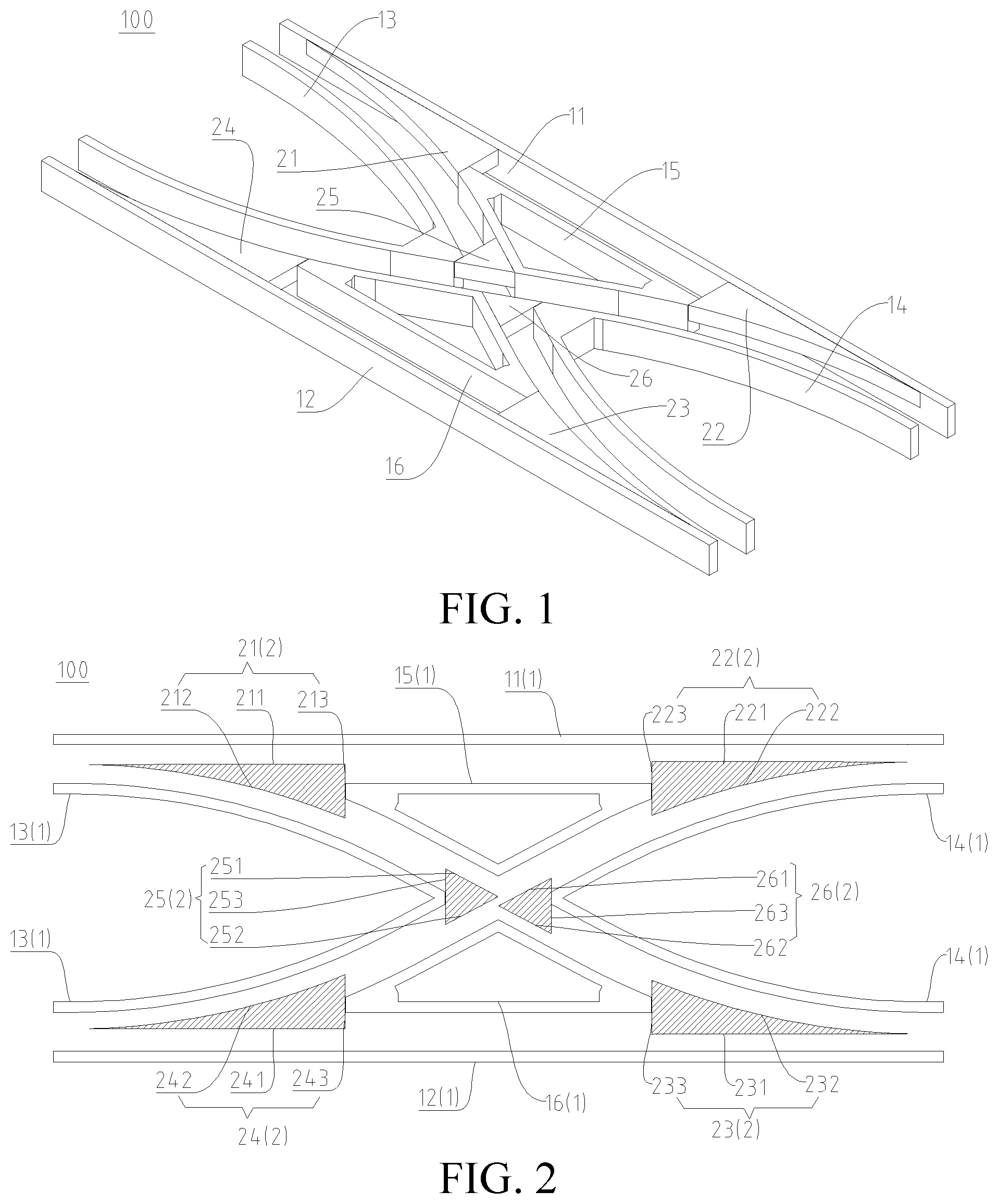
is a perspective view of an inner guide rail switch according to an embodiment of this application.
is a top view of the inner guide rail switch shown in .
is a top view of the fixed beam assembly shown in .
is a top view of a fixed beam assembly according to another embodiment of this application.
is a schematic diagram showing a first passage-permitted state and a fourth passage-permitted state of the inner guide rail switch of .
is a schematic diagram showing a second passage-permitted state of the inner guide rail switch of .
is a schematic diagram showing a third passage-permitted state of the inner guide rail switch of .
is a schematic diagram of an inner guide rail switch at a first passage-permitted state and a fourth passage-permitted state according to another embodiment of this application.
is a schematic diagram showing a second passage-permitted state of the inner guide rail switch of .
is a schematic diagram showing a third passage-permitted state of the inner guide rail switch of .
is a schematic diagram of a rail transit system according to an embodiment of this application.
LIST OF REFERENCE NUMERALS
•
• rail transit system 1000 ; • inner guide rail switch 100 ; • fixed beam assembly 1 ; • first fork 101 ; second fork 102 ; third fork 103 ; fourth fork 104 ; • first passageway 01 ; R 11 section 011 ; R 12 section 012 ; R 13 section 013 ; • second passageway 02 ; R 21 section 021 ; R 22 section 022 ; R 23 section 023 ; R 24 section 024 ; R 25 section 025 ; • third passageway 03 ; R 31 section 031 ; R 32 section 032 ; R 33 section 033 ; R 34 section 034 ; R 35 section 035 ; • fourth passageway 04 ; R 41 section 041 ; R 42 section 042 ; R 43 section 043 ; • first fixed beam 11 ; L 11 side beam section 111 ; L 12 side beam section 112 ; L 13 side beam section 113 ; • second fixed beam 12 ; L 21 side beam section 121 ; L 22 side beam section 122 ; L 23 side beam section 123 ; • third fixed beam 13 ; L 31 side beam section 131 ; L 32 side beam section 132 ; L 33 side beam section 133 ; L 34 side beam section 134 ; • first beam section 13 a ; second beam section 13 b ; third beam section 13 c; • fourth fixed beam 14 ; L 41 side beam section 141 ; L 42 side beam section 142 ; L 43 side beam section 143 ; L 44 side beam section 144 ; • fourth beam section 14 a ; fifth beam section 14 b ; sixth beam section 14 c; • fifth fixed beam 15 ; L 51 side beam section 151 ; L 52 side beam section 152 ; L 53 side beam section 153 ; • sixth fixed beam 16 ; L 61 side beam section 161 ; L 62 side beam section 162 ; L 63 side beam section 163 ; • movable beam assembly 2 ; • first movable beam 21 ; F 11 surface 211 ; F 12 surface 212 ; F 13 surface 213 ; • second movable beam 22 ; F 21 surface 221 ; F 22 surface 222 ; F 23 surface 223 ; • third movable beam 23 ; F 31 surface 231 ; F 32 surface 232 ; F 33 surface 233 ; • fourth movable beam 24 ; F 41 surface 241 ; F 42 surface 242 ; F 43 surface 243 ; • fifth movable beam 25 ; F 51 surface 251 ; F 52 surface 252 ; F 53 surface 253 ; • sixth movable beam 26 ; F 61 surface 261 ; F 62 surface 262 ; F 63 surface 263 ; • vehicle 200 ; guide wheel 201 ; walking wheel 202 ; and track beam 300 .
DETAILED DESCRIPTION
The following describes embodiments of this application in detail. Examples of the embodiments are shown in the accompanying drawings. In the accompanying drawings, the same or similar elements and elements having same or similar functions are denoted by same or similar reference numerals throughout the descriptions. The following embodiments described with reference to the accompanying drawings are exemplary to describe this application, and are not limitations to this application.
Many different embodiments or examples are provided below to implement different structures of this application. To simplify the disclosure of this application, the following describes components and settings of particular examples. Certainly, the components and settings are merely examples, and do not limit this application. In addition, in this application, reference numerals and/or letters may be repeated in different examples, but such repetitions are for simplification and clarity, which do not indicate relationships between the embodiments and/or settings discussed. Moreover, this application provides examples of various particular processes and materials, but a person of ordinary skill in the art may be aware of application of another process and/or use of another material.
An inner guide rail switch 100 according to the embodiments of this application will be described below with reference to the accompanying drawings.
Specifically, the inner guide rail switch 100 according to the embodiments of this application can be used in a rail transit system 1000 , so the rail transit system 1000 including the inner guide rail switch 100 can have the same advantages as the inner guide rail switch 100 . The concept and other components of the rail transit system 1000 , such as a subway system, a light rail system, etc., are well known to those skilled in the art, and therefore will not be described in detail herein. In addition, other components of the rail transit system 1000 according to the embodiments of this application, such as a vehicle 200 and a track beam 300 , are known to those of ordinary skill in the art, and therefore will not be described in detail herein.
As shown in and , the inner guide rail switch 100 may include: a fixed beam assembly 1 and a movable beam assembly 2 . Four forks and four passageways are defined by the fixed beam assembly 1 . The movable beam assembly 2 includes: a first movable beam 21 , a second movable beam 22 , a third movable beam 23 , a fourth movable beam 24 , a fifth movable beam 25 , and a sixth movable beam 26 . The fixed beam assembly 1 (including each of the fixed beams) is fixed, and the movable beam assembly 2 (including each of the movable beams) is movable relative to the fixed beam assembly 1 .
Referring to , the four forks are a first fork 101 , a second fork 102 , a third fork 103 , and a fourth fork 104 . The four forks are respectively located at four corners of a quadrilateral, the first fork 101 and the third fork 103 are arranged diagonally, and the second fork 102 and the fourth fork 104 are arranged diagonally. The four passageways are a first passageway 01 , a second passageway 02 , a third passageway 03 , and a fourth passageway 04 . The first passageway 01 connects the first fork 101 and the second fork 102 , the second passageway 02 connects the first fork 101 and the third fork 103 , the third passageway 03 connects the fourth fork 104 and the second fork 102 , and the fourth passageway 04 connects the fourth fork 104 and the third fork 103 .
As shown in and , the first movable beam 21 is movably arranged at the first fork 101 and is configured to move in a union area of the first passageway 01 and the second passageway 02 to switch one of the first passageway 01 and the second passageway 02 to allow passage. The second movable beam 22 is movably arranged at the second fork 102 and is configured to move in a union area of the first passageway 01 and the third passageway 03 to switch one of the first passageway 01 and the third passageway 03 to allow passage. The third movable beam 23 is movably arranged at the third fork 103 and is configured to move in a union area of the second passageway 02 and the fourth passageway 04 to switch one of the second passageway 02 and the fourth passageway 04 to allow passage. The fourth movable beam 24 is movably arranged at the fourth fork 104 and is configured to move in a union area of the third passageway 03 and the fourth passageway 04 to switch between one of the third passageway 03 and the fourth passageway 04 to allow passage. The fifth movable beam 25 is movably arranged on a side of an intersection of the second passageway 02 and the third passageway 03 close to the first fork 101 and the fourth fork 104 , and is configured to move in a union area of the second passageway 02 and the third passageway 03 to switch one of the second passageway 02 and the third passageway 03 to allow passage. The sixth movable beam 26 is movably arranged on a side of the intersection of the second passageway 02 and the third passageway 03 close to the second fork 102 and the third fork 103 , and is configured to move in the union area of the second passageway 02 and the third passageway 03 to switch one of the second passageway 02 and the third passageway 03 to allow passage. It is to be understood that the union area mentioned in this specification includes not only all areas of one passageway, but also all areas of another passageway. Taking the union area of the first passageway 01 and the second passageway 02 as an example, the union area of the passageway 01 and the second passageway 02 includes all the areas of the first passageway 01 and all areas of the second passageway 02 .
As shown in , when the first movable beam 21 moves to a position that allows passage in the first passageway 01 and blocks the second passageway 02 , and the second movable beam 22 moves to a position that allows passage in the first passageway 01 and blocks the third passageway 03 . The first movable beam 21 and the second movable beam 22 can fill a side beam gap of the first passageway 01 , and provide functions of guiding guide wheels 201 of the vehicle 200 and supporting walking wheels 202 of the vehicle 200 , so that the inner guide rail switch 100 presents at a first passage-permitted state allowing passage in the first passageway 01 .
As shown in , when the first movable beam 21 moves to a position that allows passage in the second passageway 02 and blocks the first passageway 01 , the third movable beam 23 moves to a position that allows passage in the second passageway 02 and blocks the fourth passageway 04 , and the fifth movable beam 25 and the sixth movable beam 26 both move to a position that allows passage in the second passageway 02 and blocks the third passageway 03 . The first movable beam 21 , the third movable beam 23 , the fifth movable beam 25 , and the sixth movable beam 26 can fill a side beam gap of the second passageway 02 , and guide the guide wheels 201 of the vehicle 200 and support the walking wheels 202 of the vehicle 200 , so that the inner guide rail switch 100 presents at a second passage-permitted state allowing passage in the second passageway 02 .
As shown in , when the fourth movable beam 24 moves to a position that allows passage in the third passageway 03 and blocks the fourth passageway 04 , the second movable beam 22 moves to a position that allows passage in the third passageway 03 and blocks the first passageway 01 , and the fifth movable beam 25 and the sixth movable beam 26 both move to a position that allows passage in the third passageway 03 and blocks the second passageway 02 . The fourth movable beam 24 , the second movable beam 22 , the fifth movable beam 25 , and the sixth movable beam 26 can fill a side beam gap of the third passageway 03 , and provide guiding for the guide wheels 201 of the vehicle 200 and supporting for the walking wheels 202 of the vehicle 200 , so that the inner guide rail switch 100 presents at a third passage-permitted state allowing passage in the third passageway 03 .
As shown in , when the fourth movable beam 24 moves to a position that allows passage in the fourth passageway 04 and blocks the third passageway 03 , and the third movable beam 23 moves to a position that allows passage in the fourth passageway 04 and blocks the second passageway 02 . The fourth movable beam 24 and the third movable beam 23 can fill a side beam gap of the fourth passageway 04 , and guide the guide wheels 201 of the vehicle 200 and support the walking wheels 202 of the vehicle 200 , so that the inner guide rail switch 100 presents at a first passage-permitted state allowing passage in the fourth passageway 04 .
Therefore, the inner guide rail switch 100 according to the embodiments of this application has an ingenious structure, and can switch among the four passage-permitted states by moving the positions of the movable beams of the movable beam assembly 2 so as to meet various actual traffic requirements. Moreover, because each of the movable beams of the movable beam assembly 2 is configured to move in the union area of the corresponding passageways, the movable beams will not occupy extra space outside the passageways during the movement process, thereby achieving a small overall size and low costs of the inner guide rail switch 100 . In addition, because of the inner guide rail switch 100 , there is no need to move the entire rail switch beam, so the driving force required on each movable beam is reduced, thereby reducing the difficulty in setting up the driving device and allowing for swift switching.
In addition, it should be noted that the fixing mode for the fixed beam assembly 1 (including each fixed beam) is not limited. For example, each fixed beam may be fixed to a base support, and the support base may be welded to a rail switch platform. The movement mode and driving mode for the movable beam assembly 2 (including each movable beam) are not limited. For example, each movable beam may be fixed to a corresponding trolley, the trolley includes a driving device, and the driving device drives the trolley to move so as to cause the corresponding movable beam to move. Certainly, this application is not limited thereto.
In some embodiments of this application, as shown in , the fixed beam assembly 1 may include: a first fixed beam 11 , a second fixed beam 12 , a third fixed beam 13 , a fourth fixed beam 14 , a fifth fixed beam 15 , and a sixth fixed beam 16 . The first fixed beam 11 extends from the first fork 101 to the second fork 102 . The second fixed beam 12 extends from the fourth fork 104 to the third fork 103 . The third fixed beam 13 and the fourth fixed beam 14 are both located between the first fixed beam 11 and the second fixed beam 12 . The third fixed beam 13 is located closer to the first fork 101 and the fourth fork 104 than the fourth fixed beam 14 is (that is, the fourth fixed beam 14 is located closer to the second fork 102 and the third fork 103 than the third fixed beam 13 is, that is to say, the third fixed beam 13 and the fourth fixed beam 14 are arranged in sequence along a direction from the first fork 101 to the second fork 102 , or the third fixed beam 13 and the fourth fixed beam 14 are arranged in sequence along a direction from the fourth fork 104 to the third fork 103 ). The fifth fixed beam 15 is located on a side of the third fixed beam 13 and the fourth fixed beam 14 close to the first fixed beam 11 (so the fifth fixed beam 15 arranged opposite to a middle part of the first fixed beam 11 ). The sixth fixed beam 16 is located on a side of the third fixed beam 13 and the fourth fixed beam 14 close to the second fixed beam 12 (so the sixth fixed beam 16 is arranged opposite to a middle part of the second fixed beam 12 ). Therefore, the fixed beam assembly 1 has a simple structure, is easy to process and install, has low investment costs, and has a small overall size.
In some embodiments of this application, as shown in , each of the first fixed beam 11 , the second fixed beam 12 , the third fixed beam 13 , the fourth fixed beam 14 , the fifth fixed beam 15 , and the sixth fixed beam 16 may include one or more equal-width beams. This shows that each fixed beam is not a solid block, which reduces the weight and costs of each fixed beam, thereby reducing the overall weight, costs, and construction difficulty of the inner guide rail switch 100 .
For example, in the specific embodiment shown in , the first fixed beam 11 may include one equal-width side beam which includes an L 11 side beam section 111 , an L 12 side beam section 112 , and an L 13 side beam section 113 connected in sequence. Certainly, this application is not limited thereto, and the first fixed beam 11 may also be assembled with a plurality of separately processed equal-width beams. For example, as shown in , when the first fixed beam 11 does not extend along a straight line, it may be assembled with a plurality of separately processed equal-width beams, thereby reducing the processing difficulty of the first fixed beam 11 and reducing the production costs.
For example, in the specific embodiment shown in , the second fixed beam 12 may include one equal-width side beam which includes an L 21 side beam section 121 , an L 22 side beam section 122 , and an L 23 side beam section 123 connected in sequence. Certainly, this application is not limited thereto, and the second fixed beam 12 may also be assembled with a plurality of separately processed equal-width beams. For example, as shown in , when the second fixed beam 12 does not extend along a straight line, it may be assembled with a plurality of separately processed equal-width beams, thereby reducing the processing difficulty of the second fixed beam 12 and reducing the production costs.
For example, in the specific embodiment shown in , the third fixed beam 13 may include one equal-width side beam which includes an L 31 side beam section 131 , an L 32 side beam section 132 , an L 33 side beam section 133 , and an L 34 side beam section 134 connected in sequence. Certainly, this application is not limited thereto, and the third fixed beam 13 may also be assembled with a plurality of separately processed equal-width beams. For example, as shown in , the third fixed beam 13 may also be assembled with three separately processed equal-width beams: a first beam section 13 a , a second beam section 13 b , and a third beam section 13 c . In other words, the first beam section 13 a , the second beam section 13 b , and the third beam section 13 c are separately processed equal-width beams, which are assembled together by a subsequent assembly process to constitute the third fixed beam 13 , thereby reducing the overall processing difficulty of the third fixed beam 13 and reducing the production costs.
For example, in the specific embodiment shown in , the fourth fixed beam 14 may include one equal-width side beam which includes an L 41 side beam section 141 , an L 42 side beam section 142 , an L 43 side beam section 143 , and an L 44 side beam section 144 connected in sequence. Certainly, this application is not limited thereto, and the fourth fixed beam 14 may also be assembled with a plurality of separately processed equal-width beams. For example, as shown in , the fourth fixed beam 14 may also be assembled with three separately processed equal-width beams: a fourth beam section 14 a , a fifth beam section 14 b , and a sixth beam section 14 c . In other words, the fourth beam section 14 a , the fifth beam section 14 b , and the sixth beam section 14 c are separately processed equal-width beams, which are assembled together by a subsequent assembly process to constitute the fourth fixed beam 14 , thereby reducing the overall processing difficulty of the fourth fixed beam 14 and reducing the production costs.
For example, in the specific embodiment shown in , the fifth fixed beam 15 may include one beam with equal-width which includes an L 51 side beam section 151 , an L 52 side beam section 152 , an L 53 side beam section 153 connected in sequence in a triangular shape (that is, the L 51 side beam section 151 , the L 52 side beam section 152 , and the L 53 side beam section 153 constitute three sides of a triangle). Certainly, this application is not limited thereto, and the fifth fixed beam 15 may also be assembled with a plurality of separately processed equal-width beams, thereby reducing the processing difficulty of the fifth fixed beam 15 and reducing the production costs.
For example, in the specific embodiment shown in , the sixth fixed beam 16 may include one beam with equal-width which includes an L 61 side beam section 161 , an L 62 side beam section 162 , an L 63 side beam section 163 connected in sequence in a triangular shape (that is, the L 61 side beam section 161 , the L 62 side beam section 162 , and the L 63 side beam section 163 constitute three sides of a triangle). Certainly, this application is not limited thereto, and the sixth fixed beam 16 may also be assembled with a plurality of separately processed equal-width beams, thereby reducing the processing difficulty of the sixth fixed beam 16 and reducing the production costs.
As shown in , the first fork 101 is located between the first fixed beam 11 and the third fixed beam 13 , the second fork 102 is located between the first fixed beam 11 and the fourth fixed beam 14 , the third fork 103 is located between the second fixed beam 12 and the fourth fixed beam 14 , and the fourth fork 104 is located between the second fixed beam 12 and the third fixed beam 13 .
As shown in , the first passageway 01 includes an R 11 section 011 , an R 12 section 012 , and an R 13 section 013 arranged in sequence. The R 11 section 011 is located between the first fixed beam 11 and the third fixed beam 13 (for example, the R 11 section 011 is located between the L 11 side beam section 111 and the L 31 side beam section 131 ). The R 12 section 012 is located between the first fixed beam 11 and the fifth fixed beam 15 (for example, the R 12 section 012 is located between the L 12 side beam section 112 and the L 51 side beam section 151 ). The R 13 section 013 is located between the first fixed beam 11 and the fourth fixed beam 14 (for example, the R 13 section 013 is located between the L 13 side beam section 113 and the L 41 side beam section 141 ). Therefore, the fixed beam assembly 1 has a simple structure, and the first passageway 01 can be defined easily and efficiently.
As shown in , the second passageway 02 includes an R 21 section 021 , an R 22 section 022 , an R 23 section 023 , an R 24 section 024 , and an R 25 section 025 arranged in sequence. The R 21 section 021 is located between the first fixed beam 11 and the third fixed beam 13 (for example, the R 21 section 021 is located between the L 11 side beam section 111 and the L 31 side beam section 131 ). The R 22 section 022 is located between the third fixed beam 13 and the fifth fixed beam 15 (for example, the R 22 section 022 is located between the L 52 side beam section 152 and the L 32 side beam section 132 ). The R 24 section 024 is located between the fourth fixed beam 14 and the sixth fixed beam 16 (for example, the R 24 section 024 is located between the L 43 side beam section 143 and the L 63 side beam section 163 ). The R 25 section 025 is located between the fourth fixed beam 14 and the second fixed beam 12 (for example, the R 25 section 025 is located between the L 44 side beam section 144 and the L 23 side beam section 123 ). Therefore, the fixed beam assembly 1 has a simple structure, and the second passageway 02 can be defined easily and efficiently.
As shown in , the third passageway 03 includes an R 31 section 031 , an R 32 section 032 , an R 33 section 033 , an R 34 section 034 , and an R 35 section 035 arranged in sequence. The R 31 section 031 is located between the third fixed beam 13 and the second fixed beam 12 (for example, the R 31 section 031 is located between the L 21 side beam section 121 and the L 34 side beam section 134 ). The R 32 section 032 is located between the third fixed beam 13 and the sixth fixed beam 16 (for example, the R 32 section 032 is located between the L 33 side beam section 133 and the L 62 side beam section 162 ). The R 34 section 034 is located between the fifth fixed beam 15 and the sixth fixed beam 14 (for example, the R 34 section 034 is located between the L 42 side beam section 142 and the L 53 side beam section 153 ). The R 35 section 035 is located between the first fixed beam 11 and the fourth fixed beam 14 (for example, the R 35 section 035 is located between the L 41 side beam section 141 and the L 13 side beam section 113 ). Therefore, the fixed beam assembly 1 has a simple structure, and the third passageway 03 can be defined easily and efficiently.
As shown in , the fourth passageway 04 includes an R 41 section 041 , an R 42 section 042 , and an R 43 section 043 arranged in sequence. The R 41 section 041 is located between the third fixed beam 13 and the second fixed beam 12 (for example, the R 41 section 041 is located between the L 34 side beam section 134 and the L 21 side beam section 121 ). The R 42 section 042 is located between the sixth fixed beam 16 and the second fixed beam 12 (for example, the R 42 section 042 is located between the L 61 side beam section 161 and the L 22 side beam section 122 ). The R 43 section 043 is located between the fourth fixed beam 14 and the second fixed beam 12 (for example, the R 43 section 043 is located between the L 44 side beam section 144 and the L 23 side beam section 123 ). Therefore, the fixed beam assembly 1 has a simple structure, and the fourth passageway 04 can be defined easily and efficiently.
In some embodiments of this application, as shown in , at least (the center line of) a middle part of the R 12 section 012 may extend along a straight line, at least (the center line of) a middle part of the R 42 section 042 may extend along a straight line, and the extension line of (the center line of) the middle part of the R 12 section 012 may be parallel to the extension line of (the center line of) the middle part of the R 42 section 042 . Certainly, this application is not limited thereto. For example, in some other embodiments of this application, the center line of the R 12 section 012 may also extend along a curve, and the center line of the R 42 section 042 may also extend along a curve.
In some embodiments of this application, as shown in , (the center line) of the R 23 section 023 extends along a straight line, an extension line of (the center line of) at least a part of the R 22 section 022 that is connected to the R 23 section 023 coincides with an extension line of (the center line of) the R 23 section 023 , and an extension line of (the center line of) at least a part of the R 24 section 024 that is connected to the R 23 section 023 coincides with the extension line of (the center line of) the R 23 section 023 . Therefore, the vehicle 200 can pass smoothly when traveling from the R 22 section 022 to the R 24 section 024 , thereby reducing the shaking of the vehicle 200 and improving the riding comfort. Moreover, the length of the second passageway 02 can be shortened, to ensure that the inner guide rail switch 100 has a small size.
In some embodiments of this application, as shown in , (the center line) of the R 33 section 033 extends along a straight line, an extension line of (the center line of) at least a part of the R 32 section 032 that is connected to the R 33 section 033 coincides with an extension line of (the center line of) the R 33 section 033 , and an extension line of (the center line of) at least a part of the R 34 section 034 that is connected to the R 33 section 033 coincides with the extension line of (the center line of) the R 33 section 033 . Therefore, the vehicle 200 can pass smoothly when traveling from the R 32 section 032 to the R 34 section 034 , thereby reducing the shaking of the vehicle 200 and improving the riding comfort. Moreover, the length of the third passageway 03 can be shortened, to ensure that the inner guide rail switch 100 has a small size.
In some embodiments of this application, as shown in and , the first movable beam 21 is located on one side of the fifth fixed beam 15 close to the first fork 101 and is configured to translate between the first fixed beam 11 and the third fixed beam 13 , and the first movable beam 21 includes an F 11 surface 211 facing the first fixed beam 11 and an F 12 surface 212 facing the third fixed beam 13 . When the first movable beam 21 moves to a position where the F 11 surface 211 is joined to a side surface of the fifth fixed beam 15 facing the first fixed beam 11 (as shown in ), the first movable beam 21 and the first fixed beam 11 (for example, the L 11 side beam section 111 ) constitute two side beams of the R 11 section 011 . When the first movable beam 21 moves to a position where the F 12 surface 212 is joined to a side surface of the fifth fixed beam 15 facing the third fixed beam 13 (as shown in ), the first movable beam 21 and the third fixed beam 13 (for example, the L 31 side beam section 131 ) constitute two side beams of the R 21 section 021 . The first movable beam 21 may be an integrally formed part, i.e., an integral part. In other words, the first movable beam 21 is not assembled with a plurality of parts, and does not include a plurality of scattered parts.
It needs to be noted that the term “join” and variants thereof mentioned in this specification refers to smooth transition connection.
Therefore, the first movable beam 21 has a simple structure and can reliably move in the union area of the first passageway 01 and the second passageway 02 , and switching between the first passageway 01 and the second passageway 02 can be easily and effectively realized by translational movement. In short, the first movable beam 21 has a simple structure and is easy to process, and the driving device for driving the first movable beam 21 to undergo translation movement has a simple structure and requires low energy consumption for driving.
Certainly, this application is not limited thereto. For example, in some other embodiments of this application, the first movable beam 21 may also include a plurality of components, which may or may not be connected. Each component may be driven by one driving device, and each component may also be driven to move along a curve, and so on, which will not be described in detail herein.
In some embodiments of this application, as shown in , when the first movable beam 21 moves to a position where the F 11 surface 211 is joined to the side surface of the fifth fixed beam 15 facing the first fixed beam 11 , the F 12 surface 212 is in contact with the third fixed beam 13 . In this way, the first fixed beam 11 can be used to support the first movable beam 21 to improve the stability of the first movable beam 21 when staying in the switching position, ensure a reliable guiding of the first movable beam 21 for the guide wheels 201 , and ensure a reliable supporting of the first movable beam 21 for the walking wheels 202 .
In some embodiments of this application, as shown in , when the first movable beam 21 moves to a position where the F 12 surface 212 is joined to the side surface of the fifth fixed beam 15 facing the third fixed beam 13 , the F 11 surface 211 is in contact with the third fixed beam 11 . In this way, the third fixed beam 13 can be used to support the first movable beam 21 to improve the stability of the first movable beam 21 when staying in the switching position, ensure reliable guiding of the first movable beam 21 for the guide wheels 201 , and ensure reliable supporting of the first movable beam 21 for the walking wheels 202 .
In some embodiments of this application, as shown in and , the first movable beam 21 may further include an F 13 surface 213 facing the fifth fixed beam 15 , the F 13 surface 213 extends along a direction parallel to a translation direction of the first movable beam 21 , and the side surface of the fifth fixed beam 15 facing the first movable beam 21 is constructed as a planar structure parallel to the F 13 surface 213 . This means that the fifth fixed beam 15 is in surface contact with the first movable beam 21 , so that there is a certain beam width at the position where the fifth fixed beam 15 and the first movable beam 21 are butted. In this way, when the walking wheels 202 of the vehicle 200 travel from the first movable beam 21 to the fifth fixed beam 15 (or from the fifth fixed beam 15 to the first movable beam 21 ), no wheel trapping will occur at the joint between the fifth fixed beam 15 and the first movable beam 21 . Moreover, when the first movable beam 21 is joined to the fifth fixed beam 15 , the F 13 surface 213 can be used to form a surface contact with the above-mentioned planar structure of the fifth fixed beam 15 to reliably support the first movable beam 21 , so as to ensure that the first movable beam 21 can stably stay in the switching position, ensure reliable guiding of the first movable beam 21 for the guide wheels 201 , and ensure reliable supporting of the first movable beam 21 for the walking wheels 202 .
In some embodiments of this application, as shown in and , the second movable beam 22 is located on one side of the fifth fixed beam 15 close to the second fork 102 and is configured to translate between the first fixed beam 11 and the fourth fixed beam 14 , and the second movable beam 22 includes an F 21 surface 221 facing the first fixed beam 11 and an F 22 surface 222 facing the fourth fixed beam 14 . When the second movable beam 22 moves to a position where the F 21 surface 221 is joined to a side surface of the fifth fixed beam 15 facing the first fixed beam 11 (as shown in ), the second movable beam 22 and the first fixed beam 11 (for example, the L 13 side beam section 113 ) constitute two side beams of the R 13 section 013 . When the second movable beam 22 moves to a position where the F 22 surface 222 is joined to a side surface of the fifth fixed beam 15 facing the fourth fixed beam 14 (as shown in ), the second movable beam 22 and the fourth fixed beam 14 (for example, the L 41 side beam section 141 ) constitute two side beams of the R 35 section 035 . The second movable beam 22 may be an integrally formed part, i.e., an integral part. In other words, the second movable beam 22 is not assembled with a plurality of parts, and does not include a plurality of scattered parts.
Therefore, the second movable beam 22 has a simple structure and can reliably move in the union area of the first passageway 01 and the third passageway 03 , and switching between the first passageway 01 and the third passageway 03 can be easily and effectively realized by translational movement. In short, the first movable beam 22 has a simple structure and is easy to process, and the driving device for driving the second movable beam 22 to undergo translation movement has a simple structure and requires low energy consumption for driving.
Certainly, this application is not limited thereto. For example, in some other embodiments of this application, the second movable beam 22 may also include a plurality of components, which may or may not be connected. Each component may be driven by one driving device, and each component may also be driven to move along a curve, and so on, which will not be described in detail herein.
In some embodiments of this application, as shown in , when the second movable beam 22 moves to a position where the F 21 surface 221 is joined to the side surface of the fifth fixed beam 15 facing the first fixed beam 11 , the F 22 surface 222 is in contact with the fourth fixed beam 14 . In this way, the fourth fixed beam 14 can be used to support the second movable beam 22 to improve the stability of the second movable beam 22 when staying in the switching position, ensure reliable guiding of the second movable beam 22 for the guide wheels 201 , and ensure reliable supporting of the second movable beam 22 for the walking wheels 202 .
In some embodiments of this application, as shown in , when the second movable beam 22 moves to a position where the F 22 surface 222 is joined to the side surface of the fifth fixed beam 15 facing the fourth fixed beam 14 , the F 21 surface 221 is in contact with the first fixed beam 11 . In this way, the first fixed beam 11 can be used to support the second movable beam 22 to improve the stability of the second movable beam 22 when staying in the switching position, ensure reliable guiding of the second movable beam 22 for the guide wheels 201 , and ensure reliable supporting of the second movable beam 22 for the walking wheels 202 .
In some embodiments of this application, as shown in and , the second movable beam 22 may further include an F 23 surface 223 facing the fifth fixed beam 15 , the F 23 surface 223 extends along a direction parallel to a translation direction of the second movable beam 22 , and the side surface of the fifth fixed beam 15 facing the second movable beam 22 is constructed as a planar structure parallel to the F 23 surface 223 . This means that the fifth fixed beam 15 is in surface contact with the second movable beam 22 , so that there is a certain beam width at the position where the fifth fixed beam 15 and the second movable beam 22 are butted. In this way, when the walking wheels 202 of the vehicle 200 travel from the second movable beam 22 to the fifth fixed beam 15 (or from the fifth fixed beam 15 to the second movable beam 22 ), no wheel trapping will occur at the joint between the fifth fixed beam 15 and the second movable beam 22 . Moreover, when the second movable beam 22 is joined to the fifth fixed beam 15 , the F 23 surface 223 can be used to form a surface contact with the above-mentioned planar structure of the fifth fixed beam 15 to reliably support the second movable beam 22 , so as to ensure that the second movable beam 22 can stably stay in the switching position, ensure reliable guiding of the second movable beam 22 for the guide wheels 201 , and ensure reliable supporting of the second movable beam 22 for the walking wheels 202 .
In some embodiments of this application, as shown in and , the third movable beam 23 is located on a side of the sixth fixed beam 16 close to the third fork 103 and configured to translate between the second fixed beam 12 and the fourth fixed beam 14 , and the third movable beam 23 includes an F 31 surface 231 facing the second fixed beam 12 and an F 32 surface 232 facing the fourth fixed beam 14 . When the third movable beam 23 moves to a position where the F 31 surface 231 is joined to a side surface of the sixth fixed beam 16 facing the second fixed beam 12 (as shown in ), the third movable beam 23 and the second fixed beam 12 (for example, the L 23 side beam section 123 ) constitute two side beams of the R 43 section 043 . When the third movable beam 23 moves to a position where the F 32 surface 232 is joined to a side surface of the sixth fixed beam 16 facing the fourth fixed beam 14 (as shown in ), the third movable beam 23 and the fourth fixed beam 14 (for example, the L 44 side beam section 144 ) constitute two side beams of the R 25 section 025 . The third movable beam 23 may be an integrally formed part, i.e., an integral part. In other words, the third movable beam 23 is not assembled with a plurality of parts, and does not include a plurality of scattered parts.
Therefore, the third movable beam 23 has a simple structure and can reliably move in the union area of the second passageway 02 and the fourth passageway 04 , and switching between the second passageway 02 and the fourth passageway 04 can be easily and effectively realized by translational movement. In short, the third movable beam 23 has a simple structure and is easy to process, and the driving device for driving the third movable beam 23 to undergo translation movement has a simple structure and requires low energy consumption for driving.
Certainly, this application is not limited thereto. For example, in some other embodiments of this application, the third movable beam 23 may also include a plurality of components, which may or may not be connected. Each component may be driven by one driving device, and each component may also be driven to move along a curve, and so on, which will not be described in detail herein.
In some embodiments of this application, as shown in , when the third movable beam 23 moves to a position where the F 31 surface 231 is joined to the side surface of the sixth fixed beam 16 facing the second fixed beam 12 , the F 32 surface 232 is in contact with the fourth fixed beam 14 . In this way, the fourth fixed beam 14 can be used to support the third movable beam 23 to improve the stability of the third movable beam 23 when staying in the switching position, ensure reliable guiding of the third movable beam 23 for the guide wheels 201 , and ensure reliable supporting of the third movable beam 23 for the walking wheels 202 .
In some embodiments of this application, as shown in , when the third movable beam 23 moves to a position where the F 32 surface 232 is joined to the side surface of the sixth fixed beam 16 facing the fourth fixed beam 14 , the F 31 surface 231 is in contact with the second fixed beam 12 . In this way, the second fixed beam 12 can be used to support the third movable beam 23 to improve the stability of the third movable beam 23 when staying in the switching position, ensure reliable guiding of the third movable beam 23 for the guide wheels 201 , and ensure reliable supporting of the third movable beam 23 for the walking wheels 202 .
In some embodiments of this application, as shown in and , the third movable beam 23 further includes an F 33 surface 233 facing the sixth fixed beam 16 , the F 33 surface 233 extends along a direction parallel to a translation direction of the third movable beam 23 , and a side surface of the sixth fixed beam 16 facing the third movable beam 23 is constructed as a planar structure parallel to the F 33 surface 233 . This means that the sixth fixed beam 16 is in surface contact with the third movable beam 23 , so that there is a certain beam width at the position where the sixth fixed beam 16 and the third movable beam 23 are butted. In this way, when the walking wheels 202 of the vehicle 200 travel from the third movable beam 23 to the sixth fixed beam 16 (or from the sixth fixed beam 16 to the third movable beam 23 ), no wheel trapping will occur at the joint between the sixth fixed beam 16 and the third movable beam 23 . Moreover, when the third movable beam 23 is joined to the sixth fixed beam 16 , the F 33 surface 233 can be used to form a surface contact with the above-mentioned planar structure of the sixth fixed beam 16 to reliably support the third movable beam 23 , so as to ensure that the third movable beam 23 can stably stay in the switching position, ensure reliable guiding of the third movable beam 23 for the guide wheels 201 , and ensure reliable supporting of the third movable beam 23 for the walking wheels 202 .
In some embodiments of this application, as shown in and , the fourth movable beam 24 is located on a side of the sixth fixed beam 16 close to the fourth fork 104 and configured to translate between the second fixed beam 12 and the third fixed beam 13 , and the fourth movable beam 24 includes an F 41 surface 241 facing the second fixed beam 12 and an F 42 surface 242 facing the third fixed beam 13 . When the fourth movable beam 24 moves to a position where the F 41 surface 241 is joined to a side surface of the sixth fixed beam 16 facing the second fixed beam 12 (as shown in ), the fourth movable beam 24 and the second fixed beam 12 (for example, the L 21 side beam section 121 ) constitute two side beams of the R 41 section 041 . When the fourth movable beam 24 moves to a position where the F 42 surface 242 is joined to a side surface of the sixth fixed beam 16 facing the third fixed beam 13 (as shown in ), the fourth movable beam 24 and the third fixed beam 13 (for example, the L 34 side beam section 134 ) constitute two side beams of the R 31 section 031 . The fourth movable beam 24 may be an integrally formed part, i.e., an integral part. In other words, the fourth movable beam 24 is not assembled with a plurality of parts, and does not include a plurality of scattered parts.
Therefore, the fourth movable beam 24 has a simple structure and can reliably move in the union area of the third passageway 03 and the fourth passageway 04 , and switching between the third passageway 03 and the fourth passageway 04 can be easily and effectively realized by translational movement. In short, the fourth movable beam 24 has a simple structure and is easy to process, and the driving device for driving the fourth movable beam 24 to undergo translation movement has a simple structure and requires low energy consumption for driving.
Certainly, this application is not limited thereto. For example, in some other embodiments of this application, the fourth movable beam 24 may also include a plurality of components, which may or may not be connected. Each component may be driven by one driving device, and each component may also be driven to move along a curve, and so on, which will not be described in detail herein.
In some embodiments of this application, as shown in , when the fourth movable beam 24 moves to a position where the F 41 surface 241 is joined to the side surface of the sixth fixed beam 16 facing the second fixed beam 12 , the F 42 surface 242 is in contact with the third fixed beam 13 . In this way, the third fixed beam 13 can be used to support the fourth movable beam 24 to improve the stability of the fourth movable beam 24 when staying in the switching position, ensure reliable guiding of the fourth movable beam 24 for the guide wheels 201 , and ensure reliable supporting of the fourth movable beam 24 for the walking wheels 202 .
In some embodiments of this application, as shown in , when the fourth movable beam 24 moves to a position where the F 42 surface 242 is joined to the side surface of the sixth fixed beam 16 facing the third fixed beam 13 , the F 41 surface 241 is in contact with the second fixed beam 12 . In this way, the second fixed beam 12 can be used to support the fourth movable beam 24 to improve the stability of the fourth movable beam 24 when staying in the switching position, ensure reliable guiding of the fourth movable beam 24 for the guide wheels 201 , and ensure reliable supporting of the fourth movable beam 24 for the walking wheels 202 .
In some embodiments of this application, as shown in and , the third movable beam 24 further includes an F 43 surface 243 facing the sixth fixed beam 16 , the F 43 surface 243 extends along a direction parallel to a translation direction of the fourth movable beam 24 , and a side surface of the sixth fixed beam 16 facing the fourth movable beam 24 is constructed as a planar structure parallel to the F 43 surface 243 . This means that the sixth fixed beam 16 is in surface contact with the fourth movable beam 24 , so that there is a certain beam width at the position where the sixth fixed beam 16 and the fourth movable beam 24 are butted. In this way, when the walking wheels 202 of the vehicle 200 travel from the fourth movable beam 24 to the sixth fixed beam 16 (or from the sixth fixed beam 16 to the fourth movable beam 24 ), no wheel trapping will occur at the joint between the sixth fixed beam 16 and the fourth movable beam 24 . Moreover, when the fourth movable beam 24 is joined to the sixth fixed beam 16 , the F 13 surface 213 can be used to form a surface contact with the above-mentioned planar structure of the sixth fixed beam 16 to reliably support the fourth movable beam 24 , so as to ensure that the fourth movable beam 24 can stably stay in the switching position, ensure reliable guiding of the fourth movable beam 24 for the guide wheels 201 , and ensure reliable supporting of the fourth movable beam 24 for the walking wheels 202 .
In some embodiments of this application, as shown in and , the fifth movable beam 25 is located on a side of the third fixed beam 13 close to the fourth fork 104 and configured to translate between the fifth fixed beam 15 and the sixth fixed beam 16 , and the fifth movable beam 25 includes an F 51 surface 251 facing the fifth fixed beam 15 and an F 52 surface 252 facing the sixth fixed beam 16 . The sixth movable beam 26 is located between the fourth fixed beam 14 and the fifth movable beam 25 and configured to reciprocally translate between the fifth fixed beam 15 and the sixth fixed beam 16 , and the sixth movable beam 26 includes an F 61 surface 261 facing the fifth fixed beam 15 and an F 62 surface 262 facing the sixth fixed beam 16 . The fifth movable beam 25 may be an integrally formed part, i.e., an integral part. In other words, the fifth movable beam 25 is not assembled with a plurality of parts, and does not include a plurality of scattered parts. The sixth movable beam 26 may be an integrally formed part, i.e., an integral part. In other words, the sixth movable beam 26 is not assembled with a plurality of parts, and does not include a plurality of scattered parts.
As shown in and , when the fifth movable beam 25 moves to a position where the F 52 surface 252 is joined between a side surface of the third fixed beam 13 facing the sixth fixed beam 16 and the side surface of the fifth fixed beam 15 facing the fourth fixed beam 14 , and the sixth movable beam 26 moves to a position where the F 61 surface 261 is joined between the side surface of the sixth fixed beam 16 facing the third fixed beam 13 and a side surface of the fourth fixed beam 14 facing the fifth fixed beam 15 . The fifth movable beam 25 and the sixth movable beam 26 constitute two side beams of the R 33 section 033 .
As shown in and , when the fifth movable beam 25 moves to a position where the F 51 surface 251 is joined between a side surface of the third fixed beam 13 facing the fifth fixed beam 15 and the side surface of the sixth fixed beam 16 facing the fourth fixed beam 14 , and the sixth movable beam 26 moves to a position where the F 62 surface 262 is joined between the side surface of the fifth fixed beam 15 facing the third fixed beam 13 and a side surface of the fourth fixed beam 14 facing the sixth fixed beam 16 . The fifth movable beam 25 and the sixth movable beam 26 constitute two side beams of the R 23 section 023 .
Therefore, the fifth movable beam 25 has a simple structure and can reliably move in the union area of the second passageway 02 and the third passageway 03 , and switching between the second passageway 02 and the third passageway 03 can be easily and effectively realized by translational movement. In short, the fifth movable beam 25 has a simple structure and is easy to process, and the driving device for driving the fifth movable beam 25 to undergo translation movement has a simple structure and requires low energy consumption for driving. Similarly, the sixth movable beam 26 has a simple structure and can reliably move in the union area of the second passageway 02 and the third passageway 03 , and switching between the second passageway 02 and the third passageway 03 can be easily and effectively realized by translational movement. In short, the sixth movable beam 26 has a simple structure and is easy to process, and the driving device for driving the sixth movable beam 26 to undergo translation movement has a simple structure and requires low energy consumption for driving.
Certainly, this application is not limited thereto. For example, in some other embodiments of this application, the fifth movable beam 25 may also include a plurality of components, which may or may not be connected. Each component may be driven by one driving device, and each component may also be driven to move along a curve, and so on, which will not be described in detail herein. Similarly, for example, in other embodiments of this application, the sixth movable beam 26 may also include a plurality of components, which may or may not be connected. Each component may be driven by one driving device, and each component may also be driven to move along a curve, and so on, which will not be described in detail herein.
In some embodiments of this application, as shown in , when the sixth movable beam 26 moves to a position where the F 61 surface 261 is joined between the side surface of the sixth fixed beam 16 facing the third fixed beam 13 and a side surface of the fourth fixed beam 14 facing the fifth fixed beam 15 , the F 62 surface 262 is in contact with the sixth fixed beam 16 (for example, when the F 62 surface 262 is planar and the side surface of the sixth fixed beam 16 facing the fourth fixed beam 14 is also planar, the F 62 surface 262 may entirely be in surface contact with the sixth fixed beam 16 ). In this way, the sixth fixed beam 16 can be used to support the sixth movable beam 26 to improve the stability of the sixth movable beam 26 when staying in the switching position, ensure reliable guiding of the sixth movable beam 26 for the guide wheels 201 , and ensure reliable supporting of the sixth movable beam 26 for the walking wheels 202 .
In some embodiments of this application, as shown in , when the sixth movable beam 26 moves to a position where the F 62 surface 262 is joined between the side surface of the fifth fixed beam 15 facing the third fixed beam 13 and a side surface of the fourth fixed beam 14 facing the sixth fixed beam 16 , the F 61 surface 261 is in contact with the fifth fixed beam 15 (for example, when the F 61 surface 261 is planar and the side surface of the fifth fixed beam 15 facing the fourth fixed beam 14 is also planar, the F 61 surface 261 may entirely be in surface contact with the fifth fixed beam 15 ). In this way, the fifth fixed beam 15 can be used to support the sixth movable beam 26 to improve the stability of the sixth movable beam 26 when staying in the switching position, ensure reliable guiding of the sixth movable beam 26 for the guide wheels 201 , and ensure reliable supporting of the sixth movable beam 26 for the walking wheels 202 .
In some embodiments of this application, as shown in , when the fifth movable beam 25 moves to a position where the F 51 surface 251 is joined between the side surface of the third fixed beam 13 facing the fifth fixed beam 15 and a side surface of the sixth fixed beam 16 facing the fourth fixed beam 14 , the F 52 surface 252 is in contact with the sixth fixed beam 16 (for example, when the F 52 surface 252 is planar and the side surface of the sixth fixed beam 16 facing the third fixed beam 13 is also planar, the F 52 surface 252 may entirely be in surface contact with the sixth fixed beam 16 ). In this way, the sixth fixed beam 16 can be used to support the sixth movable beam 25 to improve the stability of the fifth movable beam 25 when staying in the switching position, ensure reliable guiding of the fifth movable beam 25 for the guide wheels 201 , and ensure reliable supporting of the fifth movable beam 25 for the walking wheels 202 .
In some embodiments of this application, as shown in , when the fifth movable beam 25 moves to a position where the F 52 surface 252 is joined between the side surface of the third fixed beam 13 facing the sixth fixed beam 16 and a side surface of the fifth fixed beam 15 facing the fourth fixed beam 14 , the F 51 surface 251 is in contact with the sixth fixed beam 15 (for example, when the F 51 surface 251 is planar and the side surface of the fifth fixed beam 15 facing the third fixed beam 13 is also planar, the F 51 surface 251 may entirely be in surface contact with the fifth fixed beam 15 ). In this way, the sixth fixed beam 15 can be used to support the fifth movable beam 25 to improve the stability of the fifth movable beam 25 when staying in the switching position, ensure reliable guiding of the fifth movable beam 25 for the guide wheels 201 , and ensure reliable supporting of the fifth movable beam 25 for the walking wheels 202 .
In some embodiments of this application, as shown in and , the fifth movable beam 25 may further include an F 53 surface 253 facing the third fixed beam 13 , the F 53 surface 253 extends along a direction parallel to a translation direction of the fifth movable beam 25 , and a side surface of the third fixed beam 13 facing the fifth movable beam 25 is constructed as a planar structure parallel to the F 53 surface 253 . This means that the third fixed beam 13 is configured for surface contact with the fifth movable beam 25 , so that there is a certain beam width at the position where the third fixed beam 13 and the fifth movable beam 25 are butted. In this way, when the walking wheels 202 of the vehicle 200 travel from the fifth movable beam 25 to the third fixed beam 13 (or from the third fixed beam 13 to the fifth movable beam 25 ), no wheel trapping will occur at the joint between the third fixed beam 13 and the fifth movable beam 25 . Moreover, when the fifth movable beam 25 is joined to the third fixed beam 13 , the F 53 surface 253 can be used to form a surface contact with the above-mentioned planar structure of the third fixed beam 13 to reliably support the fifth movable beam 25 , so as to ensure that the fifth movable beam 25 can stably stay in the switching position, ensure reliable guiding of the fifth movable beam 25 for the guide wheels 201 , and ensure reliable supporting of the fifth movable beam 25 for the walking wheels 202 .
In some embodiments of this application, as shown in and , the sixth movable beam 26 further includes an F 63 surface 263 facing the fourth fixed beam 14 , the F 63 surface 263 extends along a direction parallel to a translation direction of the sixth movable beam 26 , a side surface of the fourth fixed beam 14 facing the sixth movable beam 26 is constructed as a planar structure parallel to the F 63 surface 263 , and the F 63 surface 263 is parallel to the F 53 surface 253 . This means that the fourth fixed beam 14 is in surface contact with the sixth movable beam 26 , so that there is a certain beam width at the position where the fourth fixed beam 14 and the sixth movable beam 26 are butted. In this way, when the walking wheels 202 of the vehicle 200 travel from the sixth movable beam 26 to the fourth fixed beam 14 (or from the fourth fixed beam 14 to the sixth movable beam 26 ), no wheel trapping will occur at the joint between the fourth fixed beam 14 and the sixth movable beam 26 . Moreover, when the sixth movable beam 26 is joined to the fourth fixed beam 14 , the F 13 surface 213 can be used to form a surface contact with the above-mentioned planar structure of the fourth fixed beam 14 to reliably support the sixth movable beam 26 , so as to ensure that the sixth movable beam 26 can stably stay in the switching position, ensure reliable guiding of the sixth movable beam 26 for the guide wheels 201 , and ensure reliable supporting of the sixth movable beam 26 for the walking wheels 202 .
In addition, the specific structure and shape of the inner guide rail switch 100 according to the embodiments of this application are not limited, and may be as shown in - , for example. An inner guide rail switch 100 according to several embodiments of this application will be described below with reference to the accompanying drawings.
Embodiment 1
As shown in - and - , the inner guide rail switch 100 includes: a fixed beam assembly 1 and a movable beam assembly 2 . The fixed beam assembly 1 is a fixed track beam 300 . The movable beam assembly 2 can translate. Through the combination of moving the movable beams of the movable beam assembly 2 , passage in different routes can be realized. As shown in - , the inner guide rail switch 100 includes a fixed beam assembly 1 and a movable beam assembly 2 . The fixed beam assembly 1 includes six fixed beams, namely, a first fixed beam 11 to a sixth fixed beam 16 . The bottom of each fixed beam is supported by a support base, and the support base is welded to a rail switch platform, so as to fix the fixed beam. The movable beam assembly 2 includes six movable beams which can translate, namely, a first movable beam 21 to a sixth movable beam 26 . The second movable beam 22 and the fourth movable beam 24 are rightward-open movable beams. The first movable beam 21 and the third movable beam 23 are leftward-open movable beams. The fifth and sixth movable beams 25 and 26 are horizontal movable beams. The bottom of each movable beam is equipped with a trolley device, and a driving device is provided on the trolley device.
The driving device is configured to drive the trolley device to translate, so as to drive the movable beam to translate, thereby realizing route switching to switch among passage-permitted states.
As shown in , four forks and four passageways are defined by the fixed beam assembly 1 . The four forks are a first fork 101 , a second fork 102 , a third fork 103 , and a fourth fork 104 . Lines connecting the four forks form a quadrilateral. The first fork 101 and the third fork 103 are arranged diagonally. The four passageways are a first passageway 01 , a second passageway 02 , a third passageway 03 , and a fourth passageway 04 . The first passageway 01 connects the first fork 101 and the second fork 102 , the second passageway 02 connects the first fork 101 and the third fork 103 , the third passageway 03 connects the fourth fork 104 and the second fork 102 , and the fourth passageway 04 connects the fourth fork 104 and the third fork 103 .
As shown in , the first fixed beam 11 extends from the first fork 101 to the second fork 102 , and includes an L 11 side beam section 111 , an L 12 side beam section 112 , and an L 13 side beam section 113 arranged in sequence along a direction from the first fork 101 to the second fork 102 , so that the first fixed beam 11 is a strip beam including the L 11 side beam section 111 , the L 12 side beam section 112 , and the L 13 side beam section 113 . The second fixed beam 12 extends from the fourth fork 104 to the third fork 103 , and includes an L 21 side beam section 121 , an L 22 side beam section 122 , and an L 23 side beam section 123 arranged in sequence along a direction from the fourth fork 104 to the third fork 103 , so that the second fixed beam 12 is a strip beam including the L 21 side beam section 121 , the L 22 side beam section 122 , and the L 23 side beam section 123 .
As shown in , the third fixed beam 13 and the fourth fixed beam 14 are both located between the first fixed beam 11 and the second fixed beam 12 , and the third fixed beam 13 and the fourth fixed beam 14 are arranged in sequence along the direction from the first fork 101 to the second fork 102 . The third fixed beam 13 includes an L 31 side beam section 131 , an L 32 side beam section 132 , an L 33 side beam section 133 , and an L 34 side beam section 134 arranged in sequence along a direction from the first fork 101 to the fourth fixed beam 14 and then to the fourth fork 104 . The L 31 side beam section 131 and the L 32 side beam section 132 are arranged close to the first fixed beam 11 and form an A 1 beam. The L 33 side beam section 133 and the L 34 side beam section 134 are arranged close to the second fixed beam 12 and form an A 2 beam. The A 1 beam and the A 2 beam form a “V”-shaped beam with an opening facing away from the fourth fixed beam 14 . The fourth fixed beam 14 includes an L 41 side beam section 141 , an L 42 side beam section 142 , an L 43 side beam section 143 , and an L 44 side beam section 144 arranged in sequence along a direction from the second fork 102 to the third fixed beam 13 and then to the third fork 103 . The L 41 side beam section 141 and the L 42 side beam section 142 are arranged close to the first fixed beam 11 and form a B 1 beam. The L 43 side beam section 143 and the L 44 side beam section 144 are arranged close to the second fixed beam 12 and form a B 2 beam. The B 1 beam and the B 2 beam form a “V”-shaped beam with an opening facing away from the third fixed beam 13 .
As shown in , the fifth fixed beam 15 is located on a side of the third fixed beam 13 and the fourth fixed beam 14 close to the first fixed beam 11 . The fifth fixed beam 15 is arranged opposite to a middle part of the first fixed beam 11 . The fifth fixed beam 15 includes an L 51 side beam section 151 , an L 52 side beam section 152 , and an L 53 side beam section 153 arranged in sequence. The L 51 side beam section 151 , the L 52 side beam section 152 , and the L 53 side beam section 153 constitute three sides of a triangle. The L 51 side beam section 151 is disposed facing the L 12 side beam section 112 of the first fixed beam 11 . The L 52 side beam section 152 is disposed facing the L 32 side beam section 132 of the third fixed beam 13 . The L 53 side beam section 153 is disposed facing the L 42 side beam section 142 of the four fixed beam 14 .
As shown in , the sixth fixed beam 16 is located on a side of the third fixed beam 13 and the fourth fixed beam 14 close to the second fixed beam 12 . The sixth fixed beam 16 is arranged opposite to a middle part of the second fixed beam 12 . The sixth fixed beam 16 includes an L 61 side beam section 161 , an L 62 side beam section 162 , and an L 63 side beam section 163 arranged in sequence. The L 61 side beam section 161 , the L 62 side beam section 162 , and the L 63 side beam section 163 constitute three sides of a triangle. The L 61 side beam section 161 is disposed facing the L 22 side beam section 122 of the first fixed beam 12 . The L 62 side beam section 162 is disposed facing the L 33 side beam section 133 of the third fixed beam 13 . The L 63 side beam section 163 is disposed facing the L 43 side beam section 143 of the four fixed beam 14 .
As shown in , the first passageway 01 includes an R 11 section 011 , an R 12 section 012 , and an R 13 section 013 arranged in sequence. The R 11 section 011 is located between the L 11 side beam section 111 and the L 31 side beam section 131 . The R 12 section 012 is located between the L 12 side beam section 112 and the L 51 side beam section 151 . The R 13 section 013 is located between the L 13 side beam section 113 and the L 41 side beam section 141 .
As shown in , the second passageway 02 includes an R 21 section 021 , an R 22 section 022 , an R 23 section 023 , an R 24 section 024 , an R 25 section 025 arranged in sequence. The R 21 section 021 is located between the L 11 side beam section 111 and the L 31 side beam section 131 . The R 22 section 022 is located between the L 52 side beam section 152 and the L 32 side beam section 132 . The R 24 section 024 is located between the L 43 side beam section 143 and the L 63 side beam section 163 . The R 25 section 025 is located between the L 44 side beam section 144 and the L 23 side beam section 123 .
As shown in , the third passageway 03 includes an R 31 section 031 , an R 32 section 032 , an R 33 section 033 , an R 34 section 034 , an R 35 section 035 arranged in sequence. The R 31 section 031 is located between the L 21 side beam section 121 and the L 34 side beam section 134 . The R 32 section 032 is located between the L 33 side beam section 133 and the L 62 side beam section 162 . The R 34 section 034 is located between the L 42 side beam section 142 and the L 53 side beam section 153 . The R 35 section 035 is located between the L 41 side beam section 141 and the L 13 side beam section 113 .
As shown in , the fourth passageway 04 includes an R 41 section 041 , an R 42 section 042 , and an R 43 section 043 arranged in sequence. The R 41 section 041 is located between the L 34 side beam section 134 and the L 21 side beam section 121 . The R 42 section 042 is located between the L 61 side beam section 161 and the L 22 side beam section 122 . The R 43 section 043 is located between the L 44 side beam section 144 and the L 23 side beam section 123 .
As shown in and , the first movable beam 21 is configured to translate in a union area of the R 11 section 011 and the R 21 section 021 , so that one of the R 11 section 011 and the R 21 section 021 allows passage and the other is blocked. The second movable beam 22 is configured to translate in a union area of the R 13 section 013 and the R 35 section 035 , so that one of the R 13 section 013 and the R 35 section 035 allows passage and the other is blocked. The third movable beam 23 is configured to translate in a union area of R 25 section 025 and the R 43 section 043 , so that one of R 25 section 025 and the R 43 section 043 allows passage and the other is blocked. The fourth movable beam 24 is configured to translate in a union area of the R 31 section 031 and the R 41 section 041 , so that one of the R 31 section 031 and the R 41 section 041 allows passage and the other is blocked.
As shown in and , the fifth movable beam 25 is located on a side of the third fixed beam 13 close to the fourth fixed beam 14 and is configured to translate between the L 52 side beam section 152 and the L 62 side beam section 162 , so as to connect the R 22 section 022 to the R 23 section 023 and disconnect the R 32 section 032 from the R 33 section 033 , or disconnect the R 22 section 022 from the R 23 section 023 and connect the R 32 section 032 to the R 33 section 033 . The sixth movable beam 26 is located on a side of the fourth fixed beam 14 close to the third fixed beam 13 and is configured to translate between the L 53 side beam section 153 and the L 63 side beam section 163 , so as to connect the R 24 section 024 to the R 23 section 023 and disconnect the R 34 section 034 from the R 33 section 033 , or disconnect the R 24 section 024 from the R 23 section 023 and connect the R 34 section 034 to the R 33 section 033 .
In Embodiment 1, the first passageway 01 and the fourth passageway 04 are passageways on two sides, the second passageway 02 and the third passageway 03 are passageways crossing each other, and the first passageway 01 , the second passageway 02 , the third passageway 03 , and the fourth passageway 04 are all passageways extending along a smooth line. Along the direction from left to right in the figure, the first passageway 01 and the fourth passageway 04 are parallel straight passageways, the second passageway 02 is a “curve-curve” passageway, and the third passageway 03 is a “curve-curve” passageway. Specifically, the R 11 section 011 is a straight passageway section, the R 12 section 012 is a straight passageway section, and the R 13 section 013 is a straight passageway section. The R 21 section 021 is a curved passageway section, the R 22 section 022 is a transitional passageway section between a straight line and a curve, the R 23 section 023 is a straight passageway section, the R 24 section 024 is a transitional passageway section between a straight line and a curve, and the R 25 section 025 is a curved passageway section. The R 31 section 031 is a curved passageway section, the R 32 section 032 is a transitional passageway section between a straight line and a curve, the R 33 section 033 is a straight passageway section, the R 34 section 034 is a transitional passageway section between a straight line and a curve, and the R 35 section 035 is a curved passageway section. The R 41 section 041 is a straight passageway section, the R 42 section 042 is a straight passageway section, and the R 43 section 043 is a straight passageway section.
As shown in , when the first movable beam 21 and the second movable beam 22 are driven by the driving device to translate away from the first fixed beam 11 , and the third movable beam 23 and the fourth movable beam 24 are driven by the driving device to translate away from the second fixed beam 12 , both the first passageway 01 and the fourth passageway 04 allow passage. In this case, the inner guide rail switch 100 presents at a first passage-permitted state and a fourth passage-permitted state. In this case, the first fixed beam 11 can be used as a side beam on one side of the width of the first passageway 01 (and the beam width of the side beam may be greater than the width of the walking wheels 202 of the vehicle 200 ), and (the L 31 side beam section 131 of) the third fixed beam 13 , the first movable beam 21 , (the L 51 side beam section 151 of) the fifth fixed beam 15 , the second movable beam 22 , and (the L 41 side beam section 141 of) the fourth fixed beam 14 are joined and used as a side beam on the other side of the width of the first passageway 01 (and the beam width of the side beam may be greater than the width of the walking wheels 202 of the vehicle 200 ), so that the guide wheels 201 of the vehicle 200 can pass between the side beams on the two sides of the width of the first passageway 01 , and the walking wheels 202 of the vehicle 200 can respectively be supported by and travel on the side beams on the two sides of the width of the first passageway 01 . In this case, the second fixed beam 12 can be used as a side beam on one side of the width of the fourth passageway 04 (and the beam width of the side beam may be greater than the width of the walking wheels 202 of the vehicle 200 ), and (the L 34 side beam section 134 of) the third fixed beam 13 , the fourth movable beam 24 , (the L 61 side beam section 161 of) the sixth fixed beam 16 , the third movable beam 23 , and (the L 44 side beam section 144 of) the fourth fixed beam 14 are joined and used as a side beam on the other side of the width of the fourth passageway 04 (and the beam width of the side beam may be greater than the width of the walking wheels 202 of the vehicle 200 ), so that the guide wheels 201 of the vehicle 200 can pass between the side beams on the two sides of the width of the fourth passageway 04 , and the walking wheels 202 of the vehicle 200 can respectively be supported by and travel on the side beams on the two sides of the width of the fourth passageway 04 .
As shown in , when the first movable beam 21 and the second movable beam 22 are driven by the driving device to translate toward the first fixed beam 11 , the third movable beam 23 and the fourth movable beam 24 are driven by the driving device to translate toward the second fixed beam 12 , and the fifth movable beam 25 and the sixth movable beam 26 both translate to their right side (that is, the fifth movable beam 25 translates toward the sixth fixed beam 16 and the sixth movable beam 26 translates toward the fifth fixed beam 15 ), the second passageway 02 allows passage. In this case, the inner guide rail switch 100 presents at a second passage-permitted state. In this case, (the L 11 side beam section 111 of) the first fixed beam 11 , the first movable beam 21 , (the L 52 side beam section 152 of) the fifth fixed beam 15 , the sixth movable beam 26 , and (the L 43 side beam section 143 and the L 44 side beam section 144 of) the fourth fixed beam 14 are joined and used as a side beam on one side of the width of the second passageway 02 (and the beam width of the side beam may be greater than the width of the walking wheels 202 of the vehicle 200 ), and (the L 31 side beam section 131 and the L 32 side beam section 132 of) the third fixed beam 13 , the fourth movable beam 25 , (the L 63 side beam section 163 of) the sixth fixed beam 16 , the third movable beam 23 , and (the L 23 side beam section 123 of) the second fixed beam 12 are joined and used as a side beam on the other side of the width of the fourth passageway 02 (and the beam width of the side beam may be greater than the width of the walking wheels 202 of the vehicle 200 ), so that the guide wheels 201 of the vehicle 200 can pass between the side beams on the two sides of the width of the second passageway 02 , and the walking wheels 202 of the vehicle 200 can respectively be supported by and travel on the side beams on the two sides of the width of the second passageway 02 .
As shown in , when the first movable beam 21 and the second movable beam 22 are driven by the driving device to translate toward the first fixed beam 11 , the third movable beam 23 and the fourth movable beam 24 are driven by the driving device to translate toward the second fixed beam 12 , and the fifth movable beam 25 and the sixth movable beam 26 both translate to their left side (that is, the fifth movable beam 25 translates toward the fifth fixed beam 15 and the sixth movable beam 26 translates toward the sixth fixed beam 16 ), the third passageway 03 allows passage. In this case, the inner guide rail switch 100 presents at a third passage-permitted state. In this case, (the L 21 side beam section 121 of) the second fixed beam 12 , the fourth movable beam 24 , (the L 62 side beam section 162 of) the sixth fixed beam 16 , the sixth movable beam 26 , and (the L 42 side beam section 142 and the L 41 side beam section 141 of) the fourth fixed beam 14 are joined and used as a side beam on one side of the width of the third passageway 03 (and the beam width of the side beam may be greater than the width of the walking wheels 202 of the vehicle 200 ), and (the L 34 side beam section 134 and the L 33 side beam section 133 of) the third fixed beam 13 , the fifth movable beam 25 , (the L 53 side beam section 153 of) the fifth fixed beam 15 , the second movable beam 22 , and (the L 13 side beam section 113 of) the first fixed beam 11 are joined and used as a side beam on the other side of the width of the third passageway 03 (and the beam width of the side beam may be greater than the width of the walking wheels 202 of the vehicle 200 ), so that the guide wheels 201 of the vehicle 200 can pass between the side beams on the two sides of the width of the third passageway 03 , and the walking wheels 202 of the vehicle 200 can respectively be supported by and travel on the side beams on the two sides of the width of the third passageway 03 .
Therefore, the inner guide rail switch 100 of this embodiment of this application is small in size, cost-effective and reasonable, and route switching can be realized by moving only the movable beam assembly 2 .
Embodiment 2
As shown in - , the structure of Embodiment 2 is basically the same as that of Embodiment 1, where the same components are denoted by the same reference numerals, except that the shapes of the four passageways are different.
As shown in - , the first passageway 01 and the fourth passageway 04 are passageways on two sides, the second passageway 02 and the third passageway 03 are passageways crossing each other, and the first passageway 01 , the second passageway 02 , the third passageway 03 , and the fourth passageway 04 are all passageways extending along a smooth line. Along the direction from left to right in the figure, the second passageway 02 and the third passageway 03 are both straight passageways, the first passageway 01 is a “curve-curve” passageway, and the fourth passageway 04 is a “curve-curve” passageway. The R 11 section 011 is a curved passageway section, the R 12 section 012 is a transitional passageway section between a curve and a straight line, and the R 13 section 013 is a curved passageway section. The R 21 section 021 is a straight passageway section, the R 22 section 022 is a straight passageway section, the R 23 section 023 is a straight passageway section, the R 24 section 024 is a straight passageway section, and the R 25 section 025 is a straight passageway section. The R 31 section 031 is a straight passageway section, the R 32 section 032 is a straight passageway section, the R 33 section 033 is a straight passageway section, the R 34 section 034 is a straight passageway section, and the R 35 section 035 is a straight passageway section. The R 41 section 041 is a curved passageway section, the R 42 section 042 is a transitional passageway section between a curve and a straight line, and the R 43 section 043 is a curved passageway section.
Embodiment 3
As shown in - , the structure of Embodiment 3 is basically the same as that of Embodiment 1, where the same components are denoted by the same reference numerals, except that the shapes of the four passageways are different.
As shown in - , the first passageway 01 and the fourth passageway 04 are passageways on two sides, the second passageway 02 and the third passageway 03 are passageways crossing each other, and the first passageway 01 , the second passageway 02 , the third passageway 03 , and the fourth passageway 04 are all passageways extending along a smooth line. Along the direction from left to right in the figure, the first passageway 01 is a “curve-straight” passageway, the second passageway 02 is a “straight-curve” passageway, the third passageway 03 is a “straight-curve” passageway, and the fourth passageway 04 is a “curve-straight” passageway. Specifically, the R 11 section 011 is a curved passageway section, the R 12 section 012 is a transitional passageway section between a curve and a straight line, and the R 13 section 013 is a straight passageway section. The R 21 section 021 is a straight passageway section, the R 22 section 022 is a straight passageway section, the R 23 section 023 is a straight passageway section, the R 24 section 024 is a transitional passageway section between a curve and a straight line, and the R 25 section 025 is a curved passageway section. The R 31 section 031 is a straight passageway section, the R 32 section 032 is a straight passageway section, the R 33 section 033 is a straight passageway section, the R 34 section 034 is a transitional passageway section between a curve and a straight line, and the R 35 section 035 is a curved passageway section. The R 41 section 041 is a curved passageway section, the R 42 section 042 is a transitional passageway section between a curve and a straight line, and the R 43 section 043 is a straight passageway section.
Embodiment 4
As shown in - , the structure of Embodiment 4 is basically the same as that of Embodiment 1, where the same components are denoted by the same reference numerals, except that the shapes of the four passageways are different.
As shown in - , the first passageway 01 and the fourth passageway 04 are passageways on two sides, the second passageway 02 and the third passageway 03 are passageways crossing each other, and the first passageway 01 , the second passageway 02 , the third passageway 03 , and the fourth passageway 04 are all passageways extending along a smooth line. Along the direction from left to right in the figure, the first passageway 01 is a “curve-curve” passageway, the second passageway 02 is a straight passageway, the third passageway 03 is a “curve-straight” passageway, and the fourth passageway 04 is a “straight-curve” passageway. Specifically, the R 11 section 011 is a curved passageway section, the R 12 section 012 is a transitional passageway section between a curve and a straight line, and the R 13 section 013 is a curved passageway section. The R 21 section 021 is a straight passageway section, the R 22 section 022 is a straight passageway section, the R 23 section 023 is a straight passageway section, the R 24 section 024 is a straight passageway section, and the R 25 section 025 is a straight passageway section. The R 31 section 031 is a curved passageway section, the R 32 section 032 is a transitional passageway section between a curve and a straight line, the R 33 section 033 is a straight passageway section, the R 34 section 034 is a straight passageway section, and the R 35 section 035 is a straight passageway section. The R 41 section 041 is a straight passageway section, the R 42 section 042 is a transitional passageway section between a curve and a straight line, and the R 43 section 043 is a curved passageway section.
Embodiment 5
As shown in - , the structure of Embodiment 5 is basically the same as that of Embodiment 1, where the same components are denoted by the same reference numerals, except that the shapes of the four passageways are different.
As shown in - , the first passageway 01 and the fourth passageway 04 are passageways on two sides, the second passageway 02 and the third passageway 03 are passageways crossing each other, and the first passageway 01 , the second passageway 02 , the third passageway 03 , and the fourth passageway 04 are all passageways extending along a smooth line. Along the direction from left to right in the figure, the first passageway 01 is a “curve-curve” passageway, the second passageway 02 is a “straight-curve” passageway, the third passageway 03 is a “curve-straight” passageway, and the fourth passageway 04 is a straight passageway. Specifically, the R 11 section 011 is a curved passageway section, the R 12 section 012 is a transitional passageway section between a curve and a straight line, and the R 13 section 013 is a curved passageway section. The R 21 section 021 is a straight passageway section, the R 22 section 022 is a straight passageway section, the R 23 section 023 is a straight passageway section, the R 24 section 024 is a transitional passageway section between a curve and a straight line, and the R 25 section 025 is a curved passageway section. The R 31 section 031 is a curved passageway section, the R 32 section 032 is a transitional passageway section between a curve and a straight line, the R 33 section 033 is a straight passageway section, the R 34 section 034 is a straight passageway section, and the R 35 section 035 is a straight passageway section. The R 41 section 041 is a straight passageway section, the R 42 section 042 is a straight passageway section, and the R 43 section 043 is a straight passageway section.
Embodiment 6
As shown in - , the structure of Embodiment 6 is basically the same as that of Embodiment 1, where the same components are denoted by the same reference numerals, except that the shapes of the four passageways are different.
As shown in - , the first passageway 01 and the fourth passageway 04 are passageways on two sides, the second passageway 02 and the third passageway 03 are passageways crossing each other, and the first passageway 01 , the second passageway 02 , the third passageway 03 , and the fourth passageway 04 are all passageways extending along a smooth line. Along the direction from left to right in the figure, the first passageway 01 is a “straight-curve” passageway, the second passageway 02 is a “curve-curve” passageway, the third passageway 03 is a “curve-straight” passageway, and the fourth passageway 04 is a straight passageway. Specifically, the R 11 section 011 is a straight passageway section, the R 12 section 012 is a transitional passageway section between a curve and a straight line, and the R 13 section 013 is a curved passageway section. The R 21 section 021 is a curved passageway section, the R 22 section 022 is a transitional passageway section between a curve and a straight line, the R 23 section 023 is a straight passageway section, the R 24 section 024 is a transitional passageway section between a curve and a straight line, and the R 25 section 025 is a curved passageway section. The R 31 section 031 is a curved passageway section, the R 32 section 032 is a transitional passageway section between a curve and a straight line, the R 33 section 033 is a straight passageway section, the R 34 section 034 is a straight passageway section, and the R 35 section 035 is a straight passageway section. The R 41 section 041 is a straight passageway section, the R 42 section 042 is a straight passageway section, and the R 43 section 043 is a straight passageway section.
In the description of the present specification, the description of the reference terms “an embodiment”, “some embodiments”, “specific example”, “some examples” or the like means that specific features, structures, materials or characteristics described in combination with the embodiment are included in at least one embodiment of this application. In the present specification, the illustrative expression of the above terms is not necessarily referring to the same embodiment or example. Moreover, the described specific features, structures, materials or characteristics may be combined in any suitable manners in one or more embodiments. In addition, where there are no contradictions, the various embodiments or examples described in this specification and features of various embodiments or examples can be combined by those skilled in the art.
Although the embodiments of this application have been shown and described, persons of ordinary skill in the art should understand that various changes, modifications, replacements and variations may be made to the embodiments without departing from the principles and spirit of this application, and the scope of this application is as defined by the appended claims and their equivalents.
Figures (9)
Citations
This patent cites (15)
- US280215
- US1252662
- US4774891
- US201330355
- US201614526
- US204982560
- US107815934
- US207567578
- US207809420
- US108842526
- US208183450
- US208530595
- USS5716025
- US2006200267
- USWO-2015129524