Control Circuit for a Light Adjustment and a Tone Adjustment and an Implementation Method Thereof
Abstract
The invention discloses a light adjustment and tone adjustment control circuit, which comprises a power supply circuit and a light adjustment circuit connected with the power supply circuit. An output end of the power supply circuit is connected with a first LED light source and a second LED light source. The two LED light sources are connected in series, and the tube pressure and color temperature of the first LED light source and the second LED light source are different; the invention also discloses a realization method of a light adjustment and tone adjustment control circuit. In the present invention, at least two LED light sources with different tube pressures and color temperatures are connected in series to form a whole light source, and the output current of the power supply circuit can be changed by the light adjustment circuit to realize light adjustment and tone adjustment, which has the characteristics of simple circuit design and low operating cost.
Claims (6)
1. A control circuit for a light adjustment and a tone adjustment, comprising a power supply circuit and a light adjustment circuit connected to the power supply circuit, an output end of the power supply circuit is connected with a first LED light source and a second LED light source, the first LED light source is connected in series with the second LED light source, and a rated voltage and a color temperature of the first LED light source and those of the second LED light source are different; wherein the first LED light source comprises a plurality of first LED lamp beads, and the plurality of the first LED lamp beads are connected in series; wherein the second LED light source comprises a plurality of second LED lamp beads, and the plurality of the second LED lamp beads are connected in series; wherein the rated voltage and the color temperature of each of the first LED lamp beads are same, the rated voltage and the color temperature of each of the second LED lamp beads are same, and the rated voltage of each of the first LED lamp beads is lower than the rated voltage of each of the second LED beads; wherein the first LED light source and the second LED light source form an overall light source for a light fixture; when the power supply circuit outputs a first output current, the overall light source has a first brightness and a first color temperature, and the first color temperature is a mixed color temperature of the first LED light source and the second LED light source; and when the power supply circuit outputs a second output current that is lower than the first output current, the overall light source has a second brightness and a second color temperature, the second brightness is darker than the first brightness, and the second color temperature is the color temperature of the second LED light source.
6. A method for realizing the control circuit for a light adjustment and a tone adjustment, wherein the method comprises: connecting a first LED light source and a second LED light source with different rated voltage and color temperature in series to form an LED light source; wherein the first LED light source comprises a plurality of first LED lamp beads, and the plurality of the first LED lamp beads are connected in series; wherein the second LED light source comprises a plurality of second LED lamp beads, and the plurality of the second LED lamp beads are connected in series; and wherein the rated voltage and the color temperature of each of the first LED lamp beads are same, the rated voltage and the color temperature of each of the second LED lamp beads are same, and the rated voltage of each of the first LED lamp beads is lower than the rated voltage of each of the second LED beads; wherein the first LED light source and the second LED light source form an overall light source for a light fixture; when the power supply circuit outputs a first output current, the overall light source has a first brightness and a first color temperature, and the first color temperature is a mixed color temperature of the first LED light source and the second LED light source; and when the power supply circuit outputs a second output current that is lower than the first output current, the overall light source has a second brightness and a second color temperature, the second brightness is darker than the first brightness, and the second color temperature is the color temperature of the second LED light source supplying power to the LED light source by a power supply circuit; and adjusting an output current of the power supply circuit by the control circuit to realize the light adjustment and the tone adjustment, wherein the first LED light source comprises a first switch circuit and at least two sets of third LED lamp beads connected in series in sequence, the at least two sets of third LED lamp beads connected in series in sequence are respectively connected to the first switch circuit, and a color temperature of each set of the third LED lamp beads connected in series is different from each other.
Show 4 dependent claims
2. The control circuit for a light adjustment and a tone adjustment of claim 1 , wherein the second LED light source comprises a second switch circuit and at least two sets of fourth LED lamp beads connected in series in sequence, the at least two sets of fourth LED lamp beads connected in series in sequence are respectively connected to the second switch circuit, and a color temperature of each set of the fourth LED lamp beads connected in series is different from each other.
3. The control circuit for a light adjustment and a tone adjustment of claim 2 , wherein the color temperature of each set of the third LED lamp beads connected in series is also different from the color temperature of each set of the fourth LED lamp beads connected in series.
4. The control circuit for a light adjustment and a tone adjustment of claim 1 , wherein the light adjustment circuit is a 0-10V light adjustment circuit or a first light adjustment circuit, and the first light adjustment circuit is a resistance light adjustment circuit or thyristor light adjustment circuit.
5. The control circuit for a light adjustment and a tone adjustment of claim 1 , wherein the power supply circuit is a switching power supply or a linear power supply.
Full Description
Show full text →
TECHNICAL FIELD
The invention belongs to the technical field of light adjustment and tone adjustment of LED light sources, and in particular relates to a control circuit for a light adjustment and a tone adjustment and an implementation method thereof.
TECHNICAL BACKGROUND
With the rapid development of smart lighting, more and more functions can be realized by smart lighting. For example, many existing smart lighting can realize the function of light adjustment and tone adjustment. Light adjustment refers to adjusting the brightness of the light units. Tone adjustment refers to adjusting the color temperature of the light units, which can also be understood as adjusting the color of the light units.
The existing light adjustment and tone adjustment control circuit usually includes: an AC-to-DC unit for powering a light adjustment and tone adjustment unit and a light unit; a power supply unit used to convert the voltage of an electrical signal output by the AC to DC unit and supply power to a main control unit; the light adjustment and tone adjustment unit for adjusting the brightness and/or color temperature of the light unit according to the light adjustment and tone adjustment control signal provided by the main control unit. The tone adjustment control principle of the light adjustment and tone adjustment unit is usually as follows: when the main control unit outputs a low-level tone adjustment control signal, the warm light units are controlled to light up; when the main control unit outputs a high-level tone adjustment control signal, the cold light units are controlled to light up; when the main control unit outputs a medium-level tone adjustment control signal, the light units of both color temperatures are controlled to light up.
However, the existing light adjustment and tone adjustment control circuit has the problems of complicated circuit design, high operating cost and low user selectivity.
SUMMARY OF THE INVENTION
The objective of the present invention is to provide a control circuit for a light adjustment and a tone adjustment to solve the above-mentioned problems in the technical background. The control circuit for a light adjustment and a tone adjustment provided by the invention has the characteristics of simple circuit design, low operating cost and better user experience.
Another objective of the present invention is to provide an implementation method for a control circuit for a light adjustment and a tone adjustment.
To achieve the above objectives, the present invention provides the following technical solutions: a control circuit for a light adjustment and a tone adjustment, comprising a power supply circuit and a light adjustment circuit connected to the power supply circuit, an output end of the power supply circuit is connected with a first LED light source and a second LED light source, the first LED light source is connected in series with the second LED light source, and a tube pressure and a color temperature of the first LED light source and those of the second LED light source are different.
In order to diversify the design of the light source circuit, further, the first LED light source comprises a plurality of first LED lamp beads, and the plurality of the first LED lamp beads are connected in series in sequence or connected in parallel after connections in series. The second LED light source comprises a plurality of second LED lamp beads, and the plurality of the second LED lamp beads are connected in series in sequence or connected in parallel after connections in series. The color temperature of the first LED lamp beads and that of the second LED lamp beads are different.
In order to provide users with more options, so as to make the user experience better, further, the first LED light source comprises a first switch circuit and at least two sets of third LED lamp beads connected in series in sequence, the at least two sets of third LED lamp beads connected in series in sequence are respectively connected to the first switch circuit, and a color temperature of each set of the third LED lamp beads connected in series is different from each other. The second LED light source comprises a second switch circuit and at least two sets of fourth LED lamp beads connected in series in sequence, the at least two sets of fourth LED lamp beads connected in series in sequence are respectively connected to the second switch circuit, and a color temperature of each set of the fourth LED lamp beads connected in series is different from each other. The color temperature of each set of the third LED lamp beads connected in series is also different from the color temperature of each set of the fourth LED lamp beads connected in series.
In order to be applied to different dimmers, further, the light adjustment circuit is a 0-10V light adjustment circuit or a first light adjustment circuit, and the first light adjustment circuit is a resistance light adjustment circuit or thyristor light adjustment circuit.
In order to apply to different power supply circuits, further, the power supply circuit is a switching power supply or a linear power supply.
Further in the present invention, a method for realizing the control circuit for a light adjustment and a tone adjustment comprises:
•
• (1) connecting a first LED light source and a second LED light source with different tube pressure and color temperature in series to form an LED light source; • (2) supplying power to the LED light source by a power supply circuit; • (3) adjusting an output current of the power supply circuit by the control circuit to realize the light adjustment and the tone adjustment.
Compared with the existing technology, the beneficial effects of the present invention are:
•
• 1. According to the present invention, at least two LED light sources with different tube pressures and color temperatures are connected in series to form a light source for a light fixture, and the output current of the power supply circuit can be changed by a light adjustment circuit to realize light adjustment and tone adjustment. It has the advantages of simple circuit design and low operating cost; • 2. The first LED light source and the second LED light source of the present invention respectively comprise several LED lamp beads connected in series or in parallel with each other, so that the design of the light source circuit can be diversified; • 3. A switch circuit can be added to the first LED light source and/or the second LED light source of the present invention. The switch circuit controls the conduction of LED lamp beads with different color temperatures inside the corresponding LED light source, so as to realize the expansion of various color temperature combinations, provide users with more selectivity, and thus make the user experience better; • 4. The light adjustment circuit of the present invention can be a 0-10V light adjustment circuit, a resistance light adjustment circuit or a thyristor light adjustment circuit, so that the light source circuit of the present invention can be applied to different light adjustment circuits; • 5. The power supply circuit of the present invention can be a switching power supply or a linear power supply, and the light source circuit of the present invention can be applied to different power supply circuits.
DESCRIPTION OF FIGURES
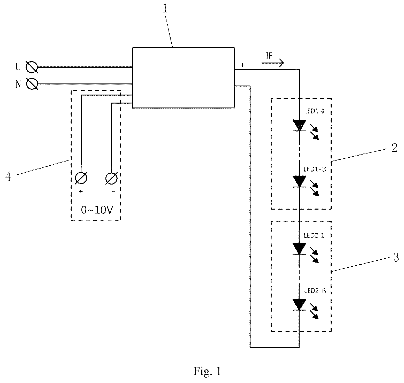
is a light adjustment and tone adjustment circuit diagram of Embodiment 1 of the present invention;
is a light adjustment and tone adjustment circuit diagram of Embodiment 2 of the present invention;
is a light adjustment and tone adjustment circuit diagram of Embodiment 3 of the present invention;
is a light adjustment and tone adjustment circuit diagram of Embodiment 4 of the present invention;
is a light adjustment and tone adjustment circuit diagram of Embodiment 5 of the present invention;
is a light adjustment and tone adjustment circuit diagram of Embodiment 6 of the present invention;
is a light adjustment and tone adjustment circuit diagram of Embodiment 7 of the present invention;
is a circuit diagram of a power supply circuit of Embodiment 7 of the present invention;
is a circuit diagram of a first LED light source and a second LED light source of Embodiment 7 of the present invention;
is a circuit diagram of a light adjustment circuit of Embodiment 7 of the present invention;
In the Figures: 1 . power supply circuit; 2 . first LED light source; 21 . first switch circuit; 3 . second LED light source; 31 . second switch circuit; 4 . 0-10V light adjustment circuit; 5 . first tone adjustment circuit.
DESCRIPTION
The technical solutions in the embodiments of the present invention will be clearly and completely described below with reference to the accompanying figures in the embodiments of the present invention. Obviously, the described embodiments are only a part of the embodiments of the present invention, but not all of the embodiments. Based on the embodiments of the present invention, all other embodiments obtained by those of ordinary skill in the art without inventive efforts shall fall within the protection scope of the present invention.
Embodiment 1
Referring to , the present invention provides the following technical solutions: a light adjustment and tone adjustment control circuit, comprising a power supply circuit 1 and a 0-10V light adjustment circuit connected to the power supply circuit 1 . The output positive terminal of the power supply circuit 1 is connected to the positive terminal of the first LED light source 2 . The negative terminal of the first LED light source 2 is connected to the positive terminal of the second LED light source 3 . The negative terminal of the second LED light source 3 is connected to the negative terminal of the power supply circuit 1 . The power supply circuit is preferably a switching power supply.
The first LED light source 2 comprises three LED 1 - 1 to LED 1 - 3 connected in series in sequence, the color temperature of LED 1 - 1 to LED 1 - 3 is 2700K, and the rated voltage of LED 1 is 3V, that is, the rated tube voltage of the first LED light source 2 is 9V.
The second LED light source 3 comprises six LED 2 - 1 to LED 2 - 6 connected in series in sequence, the color temperature of LED 2 - 1 to LED 2 - 6 is 3000K, and the rated voltage of LED 2 is 6V, that is, the rated tube voltage of the second LED light source 3 is 36V.
By adopting the above technical solution, the output current of the switching power supply is adjusted by the 0-10V light adjustment circuit. When both the first LED light source 2 and the second LED light source 3 are lit, the overall light source is highlighted, and the color temperature is 2700K+3000K mixed color display. When the output current decreases, the first LED light source 2 will gradually become darker, and the color mixing will cease. As a result, the brightness of the overall light source is reduced, and the relative power of the second LED light source 3 is greater, so the main display color temperature at this time is the color temperature of the second LED light source 3 , thereby realizing the function of light adjustment and tone adjustment.
Embodiment 2
Referring to , the difference between this Embodiment and Embodiment 1 is that the light adjustment circuit is a first light adjustment circuit 5 , and the first light adjustment circuit 5 is preferably a thyristor light adjustment circuit.
The first LED light source 2 comprises four LED 1 - 1 to LED 1 - 4 connected in series in sequence, the color temperature of LED 1 - 1 to LED 1 - 4 is 3000K, and the rated voltage of LED 1 is 3V, that is, the rated tube voltage of the first LED light source 2 is 12V.
The second LED light source 3 comprises five LED 2 - 1 to LED 2 - 5 connected in series in sequence, the color temperature of LED 2 - 1 to LED 2 - 5 is 4000K, and the rated voltage of LED 2 is 9V, that is, the rated tube voltage of the second LED light source 3 is 45V.
By adopting the above technical scheme, the output current of the switching power supply is adjusted by the thyristor light adjustment circuit. When both the first LED light source 2 and the second LED light source 3 are lit, the overall light source is highlighted, and the color temperature is 3000K+4000K mixed color display. When the output current decreases, the first LED light source 2 will gradually become darker, and the color mixing will cease. As a result, the brightness of the overall light source is reduced, and the relative power of the second LED light source 3 is greater, so the main display color temperature at this time is the color temperature of the second LED light source 3 , thereby realizing the function of light adjustment and tone adjustment.
Embodiment 3
Referring to , the difference between this Embodiment and Embodiment 2 is that the first LED light source 2 comprises a first switch circuit 21 . The first switch circuit 21 is connected with three LED 1 - 1 to LED 1 - 3 connected in series in sequence, and three LED 2 - 1 to LED 2 - 3 connected in series in sequence, wherein the color temperature of LED 1 - 1 to LED 1 - 3 is 3000K, and the color temperature of LED 2 - 1 to LED 2 - 3 is 4000K.
The second LED light source 3 comprises three LED 3 - 1 to LED 3 - 3 connected in series in sequence, and the color temperature of LED 3 - 1 to LED 3 - 3 is 5000K.
By adopting the above technical solution, on the premise that both the first LED light source 2 and the second LED light source 3 are lit, when the first switching circuit 21 turns on the LED 1 - 1 to LED 1 - 3 alone, the LED 1 - 1 to LED 1 - 3 light up, and the color temperature of the whole lamp is 3000K+5000K mixed color display.
When the first switch circuit 21 turns on LED 2 - 1 to LED 2 - 3 alone, LED 2 - 1 to LED 2 - 3 light up, and the color temperature of the whole lamp is 4000K+5000K mixed color display.
When the first switch circuit 22 turns on LED 1 - 1 to LED 1 - 3 and LED 2 - 1 to LED 2 - 3 at the same time, LED 1 - 1 to LED 1 - 3 and LED 2 - 1 to LED 2 - 3 are connected in parallel and light up at the same time. At this time, the color temperature of the whole lamp is 3500K (3000K+4000K)+5000K mixed color display.
In this embodiment, the first LED light source 2 can use two LEDs with different color temperatures to realize the combination of various color temperatures, to perform color mixing with the second LED light source 3 . They can be designed according to the needs of customers to realize the light adjustment and tone adjustment function requirements required by customers.
Embodiment 4
Referring to , the difference between this Embodiment and Embodiment 2 is that the first LED light source 2 comprises eight LED 1 - 1 to LED 1 - 8 connected in series in sequence, and the color temperature of LED 1 - 1 to LED 1 - 8 is 3000K.
The second LED light source 3 comprises a second switch circuit 31 , and the second switch circuit 31 is connected with five LED 2 - 1 to LED 2 - 5 connected in series in sequence, and five LED 3 - 1 to LED 3 - 5 connected in series in sequence, wherein the color temperature of LED 2 - 1 to LED 2 - 5 is 4000K, and the color temperature of LED 3 - 1 to LED 3 - 5 is 5000K.
By adopting the above technical solution, on the premise that both the first LED light source 2 and the second LED light source 3 are lit, when the second switch circuit 31 turns on the LED 2 - 1 to LED 2 - 5 alone, the LED 2 - 1 to LED 2 - 5 light up, and the color temperature of the whole lamp is 3000K+4000K mixed color display.
When the second switch circuit 31 turns on the LED 3 - 1 to LED 3 - 5 alone, the LED 3 - 1 to LED 3 - 5 light up, and the color temperature of the whole lamp is 3000K+5000K mixed color display.
When the second switch circuit 31 turns on LED 2 - 1 to LED 2 - 5 and LED 3 - 1 to LED 3 - 5 at the same time, LED 2 - 1 to LED 2 - 5 and LED 3 - 1 to LED 3 - 5 are connected in parallel and light up at the same time. At this time, the color temperature of the whole lamp is 3000K+4500K (4000K+5000K) mixed color display.
In this embodiment, the second LED light source 3 can use two LEDs with different color temperatures to realize the combination of various color temperatures, to perform color mixing with the first LED light source 2 . They can be designed according to the needs of customers to realize the light adjustment and tone adjustment function requirements required by customers.
Embodiment 5
Referring to , the difference between this Embodiment and Embodiment 2 is that the first LED light source 2 comprises a first switch circuit 21 , and the first switch circuit 21 is connected with three LED 1 - 1 to LED 1 - 3 connected in series in sequence, and four LED 2 - 1 to LED 2 - 4 connected in series in sequence, wherein the color temperature of LED 1 - 1 to LED 1 - 3 is 3000K, and the color temperature of LED 2 - 1 to LED 2 - 4 is 4000K.
The second LED light source 3 comprises a second switch circuit 31 . The second switch circuit 31 is connected with five LED 3 - 1 to LED 3 - 5 connected in series in sequence, and six LED 4 - 1 to LED 4 - 6 connected in series in sequence. The color temperature of LED 3 - 1 to LED 3 - 5 is 5000K, and the color temperature of LED 4 - 1 to LED 4 - 6 is 6000K.
By adopting the above technical solution, on the premise that both the first LED light source 2 and the second LED light source 3 are lit:
(1) When the first switch circuit 21 turns on LED 1 - 1 to LED 1 - 3 alone, LED 1 - 1 to LED 1 - 3 light up, and when the second switch circuit 31 turns on LED 3 - 1 to LED 3 - 5 alone, LED 3 - 1 to LED 3 - 5 light up, thus the color temperature of the whole lamp is 3000K+5000K mixed color display.
(2) When the first switch circuit 21 turns on LED 1 - 1 to LED 1 - 3 alone, LED 1 - 1 to LED 1 - 3 light up, and when the second switch circuit 31 turns on LED 4 - 1 to LED 4 - 6 alone, LED 4 - 1 to LED 4 - 6 light up, thus the color temperature of the whole lamp is 3000K+6000K mixed color display.
(3) When the first switch circuit 21 turns on LED 2 - 1 to LED 2 - 4 alone, LED 2 - 1 to LED 2 - 4 light up, and when the second switch circuit 31 turns on LED 3 - 1 to LED 3 - 5 alone, LED 3 - 1 to LED 3 - 5 light up, thus the color temperature of the whole lamp is 4000K+5000K mixed color display.
(4) When the first switch circuit 21 turns on LED 2 - 1 to LED 2 - 4 alone, LED 2 - 1 to LED 2 - 4 light up, and when the second switch circuit 31 turns on LED 4 - 1 to LED 4 - 6 alone, LED 4 - 1 to LED 4 - 6 light up, thus the color temperature of the whole lamp is 4000K+6000K mixed color display.
(5) When the first switch circuit 21 turns on LED 1 - 1 to LED 1 - 3 and LED 2 - 1 to LED 2 - 4 at the same time, LED 1 - 1 to LED 1 - 3 and LED 2 - 1 to LED 2 - 4 light up at the same time, and when the second switch circuit 31 turns on LED 3 - 1 to LED 3 - 5 alone, LED 3 - 1 to LED 3 - 5 light up, thus the color temperature of the whole lamp is 3500K (3000K+4000K)+5000K mixed color display.
(6) When the first switch circuit 21 turns on LED 1 - 1 to LED 1 - 3 and LED 2 - 1 to LED 2 - 4 at the same time, LED 1 - 1 to LED 1 - 3 and LED 2 - 1 to LED 2 - 4 light up at the same time, and when the second switch circuit 31 turns on LED 4 - 1 to LED 4 - 6 alone, LED 4 - 1 to LED 4 - 6 light up, thus the color temperature of the whole lamp is 3500K (3000K+4000K)+6000K mixed color display.
(7) When the first switch circuit 21 turns on LED 1 - 1 to LED 1 - 3 and LED 2 - 1 to LED 2 - 4 at the same time, LED 1 - 1 to LED 1 - 3 and LED 2 - 1 to LED 2 - 4 light up at the same time, and when the second switch circuit 31 turn on LED 3 - 1 to LED 3 - 5 and LED 4 - 1 to LED 4 - 6 at the same time, LED 3 - 1 to LED 3 - 5 and LED 4 - 1 to LED 4 - 6 light up at the same time, thus the color temperature of the whole lamp is 3500K (3000K+4000K)+5500K (5000K+6000K) mixed color display, and so on.
In this embodiment, both the first LED light source 2 and the second LED light source 3 can use two types of LEDs with different color temperatures to achieve a combination of various color temperatures and perform color mixing with each other to achieve more color temperature mixing options, which can be designed according to customer needs to achieve the light adjustment and tone adjustment function requirements required by customers.
Embodiment 6
Referring to , the difference between this Embodiment and Embodiment 2 is that the power supply circuit comprises a chip U 1 . Pin 1 of the chip U 1 is respectively connected to one end of the resistor RS 2 , the resistor RS 1 , the variable resistor VR 1 and the pin 4 of the rectifier bridge BD 1 . The other end of resistor RS 2 is connected to pin 2 of chip U 1 . The other end of resistor RS 1 is connected to pin 3 of chip U 1 and one end of resistor RS 3 . The other end of resistor RS 3 and variable resistor VR 1 and pin 2 of the rectifier bridge BD 1 is grounded. Pin 1 of the rectifier bridge BD 1 is connected to the fuse FR 1 . The other end of the fuse FR 1 is connected to the indicator light L 1 . The other end of the indicator light L 1 is connected to the first light adjustment circuit 5 . The first light adjustment circuit 5 is connected to the live wire L. Pin 3 of the rectifier bridge BD 1 is connected with the neutral line N. Pin 4 of the chip U 1 is connected with the resistor RS 4 . The other end of the resistor RS 4 is connected with pin 5 of the chip U 1 . Pin 5 of the chip U 1 is also connected with one end of the resistor RS 5 and the resistor RS 7 . The other end of the resistor RS 5 and the resistor RS 7 are grounded. Pin 6 of the chip U 1 is connected to one end of the resistor RS 6 . The other end of the resistor RS 6 and pin 7 of the chip U 1 are connected to the capacitor C 2 and one end of the resistor RS 8 . The other end of the resistor RS 8 is connected to the negative terminal of the second LED light source 3 . Pin 8 of the chip U 1 and the other end of the capacitor C 2 are connected to the positive terminal of the first LED light source 2 . The negative terminal of the first LED light source 2 is connected to the positive terminal of the second LED light source 3 .
The first LED light source 2 comprises two LED 1 - 1 to LED 1 - 2 connected in series in sequence, the color temperature of LED 1 - 1 to LED 1 - 2 is 4000K, and the rated voltage of LED 1 is 3V, that is, the rated tube voltage of the first LED light source 2 is 6V.
The second LED light source 3 comprises fifteen LED 2 - 1 to LED 2 - 15 connected in series in sequence, the color temperature of LED 2 - 1 to LED 2 - 15 is 5000K, and the rated voltage of LED 2 is 9V, that is, the rated tube voltage of the second LED light source 3 is 135V.
Embodiment 7
Referring to to 10 , the difference between this Embodiment and Embodiment 1 is that the power supply circuit 1 comprises a chip U 1 . Pin 1 of the chip U 1 is respectively connected to one end of the capacitor C 6 , the resistor R 12 , the resistor R 14 , the diode D 5 and the resistor R 6 . The other end of the resistor R 12 is connected to the diode D 4 and one end of the capacitor C 12 respectively. The other end of the diode D 4 is respectively connected to the resistor R 4 and pin 4 of the inductor T 1 B. Pin 5 of the inductor T 1 B and the other end of the capacitor C 12 are grounded. The other end of resistor R 4 is connected to pin 5 of chip U 1 .
The other end of resistor R 14 and diode D 5 is connected to G terminal of transistor Q 3 . The S terminal of transistor Q 3 is connected to pin 8 of chip U 1 . The D terminal of transistor Q 3 is connected to one end of the ferrite bead FB 2 . The other end of ferrite bead FB 2 is connected to diode D 3 and pin 3 of inductor T 1 A. The other end of diode D 3 is connected to one end of resistor R 8 and capacitor C 7 . The other end of resistor R 8 and capacitor C 7 are respectively connected to pin 1 of inductor T 1 A, the other end of resistor R 6 , and one end of capacitor C 3 , inductor L 2 , resistor R 1 , and capacitor C 2 . The other end of capacitor C 3 is connected to one end of resistor R 2 . The other end of the inductor L 2 is respectively connected to the other end of the resistor R 1 , one end of the capacitor C 1 and the rectifier bridge BD 1 . The other end of the rectifier bridge BD 1 and the capacitor C 1 is connected to one end of the ferrite bead FB 1 . The other end of the ferrite bead FB 1 , capacitor C 2 and resistor R 2 are grounded. The rectifier bridge BD 1 is also connected to the inductor L 1 . One end of the inductor L 1 is connected to one end of the variable resistor VR 1 and the fuse F 1 . The other end of the fuse F 1 is connected to the live wire L. One end of the inductor L 1 is connected to the other end of the variable resistor VR 1 and the neutral line N respectively. Pin 8 of the inductor T 1 A is connected to the diode D 1 . The other end of the diode D 1 is respectively connected to the capacitor C 8 , the resistor R 11 and the first LED power supply 2 . Pin 6 of the inductor T 1 A, the other end of capacitor C 8 and resistor R 11 are grounded. Pin 2 of chip U 1 is connected to resistor R 10 . Pin 3 of chip U 1 is connected to capacitor C 5 . Capacitor C 6 , resistor R 10 , capacitor C 5 and pin 4 of chip U 1 are grounded. Pin 5 of chip U 1 is also connected to resistor R 5 and capacitor C 10 respectively. Pin 6 of chip U 1 is connected to resistor RS 1 and resistor RS 2 respectively. The other end of resistor RS 1 , resistor RS 2 , capacitor C 10 and resistor R 5 are grounded.
The light adjustment circuit comprises a chip U 2 . Pin 3 of the chip U 2 are respectively connected with the resistor R 19 , the capacitor C 17 , the resistor R 20 and the switch SW. The other end of the switch SW, the resistor R 20 and the capacitor C 17 are grounded. The other ends of the switch SW and the resistor R 19 are respectively connected to the resistor R 17 , the diode ZD 1 , the capacitor C 4 and pin 8 of the chip U 2 . The other end of the diode ZD 1 and the capacitor C 4 are grounded. The other end of the resistor R 17 is connected to the resistor R 16 . The other end of the resistor R 13 is connected to the resistor R 13 . The other end of the resistor R 13 is connected to the positive terminal of the first light source LED 2 . Pin 7 of the chip U 2 is connected to the transistor Q 1 and the resistor R 7 . Pin 6 of the chip U 2 is connected to the resistor R 3 and the transistor Q 2 . The transistor Q 1 , the transistor Q 2 and pin 5 of the chip U 2 are grounded. The transistor Q 1 and the transistor Q 2 are also connected to the second LED light source 3 .
The first LED light source 2 comprises four LED 1 - 1 to LED 1 - 4 connected in parallel with each other. The second LED light source 3 comprises one set of LEDH- 1 to LEDH- 12 connected in series in sequence, one set of LEDH- 13 to LEDH- 24 connected in series in sequence, one set of LEDH- 13 to LEDH- 24 connected in series in sequence, one set of LEDL- 1 to LEDL- 12 connected in series in sequence and one set of LEDL- 13 to LEDL- 24 connected in series in sequence, wherein LEDH- 1 to LEDH- 12 , LEDH- 13 to LEDH- 24 , LEDL- 1 to LEDL- 12 , and LEDL- 13 to LEDL- 24 are connected in parallel with each other.
To sum up, in the present invention, at least two LED light sources with different tube pressures and color temperatures are connected in series to form a light source for a light fixture, and the output current of the power supply circuit can be changed by a light adjustment circuit to realize light adjustment and tone adjustment. It has the advantages of simple circuit design and low operating cost. The first LED light source and the second LED light source of the present invention respectively comprise several LED lamp beads connected in series or in parallel with each other, so that the design of the light source circuit can be diversified. A switch circuit can be added to the first LED light source and/or the second LED light source of the present invention. The switch circuit controls the conduction of LED lamp beads with different color temperatures inside the corresponding LED light source, so as to realize the expansion of various color temperature combinations, provide users with more selectivity, and thus make the user experience better. The light adjustment circuit of the present invention can be a 0-10V light adjustment circuit, a resistance light adjustment circuit or a thyristor light adjustment circuit, so that the light source circuit of the present invention can be applied to different light adjustment circuits. The power supply circuit of the present invention can be a switching power supply or a linear power supply, and the light source circuit of the present invention can be applied to different power supply circuits.
Although embodiments of the present invention have been shown and described, it will be understood by those skilled in the art that various changes, modifications, and substitutions can be made to these embodiments without departing from the principle and spirit of the invention and modifications, and that the scope of the present invention is defined by the appended claims and their equivalents.
Figures (8)
Citations
This patent cites (4)
- US20190234567
- US20210029797
- US20210185780
- US20210219395