Abstract
An audio device includes a vibration member, and a first piezoelectric vibrator and a second piezoelectric vibrator that are provided on the vibration member. A natural frequency of the first piezoelectric vibrator is larger than a natural frequency of the second piezoelectric vibrator.
Claims (19)
1. An audio device comprising: a vibration member; and a first piezoelectric vibrator and a second piezoelectric vibrator on the vibration member, wherein a natural frequency of the first piezoelectric vibrator is larger than a natural frequency of the second piezoelectric vibrator, the first piezoelectric vibrator is one of a pair of first piezoelectric vibrators, the pair of first piezoelectric vibrators is on both sides of a straight line which passes through a gravity center of a main face of the vibration member when viewed from a direction orthogonal to the main face of the vibration member, a distance between the first piezoelectric vibrator and the gravity center is shorter than a distance between the second piezoelectric vibrator and the gravity center, the pair of first piezoelectric vibrators is spaced apart from the gravity center, and the second piezoelectric vibrator is spaced apart from the gravity center.
19. An audio device comprising: a vibration member; and a first piezoelectric vibrator and a second piezoelectric vibrator on the vibration member, wherein a natural frequency of the first piezoelectric vibrator is larger than a natural frequency of the second piezoelectric vibrator, the first piezoelectric vibrator and second piezoelectric vibrator are on a main face of the vibration member, on the same side of a line passing through a gravity center of the main face, and spaced apart from each other.
Show 17 dependent claims
2. The audio device according to claim 1 , wherein a maximum length of the first piezoelectric vibrator is shorter than a maximum length of the second piezoelectric vibrator when viewed from a direction orthogonal to a main face of the vibration member.
3. The audio device according to claim 1 , wherein the first piezoelectric vibrator and the second piezoelectric vibrator are synchronously driven by a same drive signal.
4. The audio device according to claim 1 , wherein a distance between the first piezoelectric vibrator and the second piezoelectric vibrator is longer than a maximum length of the second piezoelectric vibrator when viewed from a direction orthogonal to a main face of the vibration member.
5. The audio device according to claim 1 , wherein a distance between the first piezoelectric vibrator and the second piezoelectric vibrator is shorter than a maximum length of the second piezoelectric vibrator when viewed from a direction orthogonal to a main face of the vibration member.
6. The audio device according to claim 1 , further comprising a restraint member restraining the vibration member, wherein a distance between the first piezoelectric vibrator and the restraint member is longer than a distance between the second piezoelectric vibrator and the restraint member when viewed from a direction orthogonal to a main face of the vibration member.
7. The audio device according to claim 6 , wherein a distance between the first piezoelectric vibrator and a gravity center of a main face of the vibration member is shorter than a distance between the second piezoelectric vibrator and the gravity center when viewed from a direction orthogonal to the main face.
8. The audio device according to claim 1 , further comprising a third piezoelectric vibrator on the vibration member, wherein a natural frequency of the third piezoelectric vibrator is smaller than the natural frequency of the first piezoelectric vibrator and larger than the natural frequency of the second piezoelectric vibrator.
9. The audio device according to claim 1 , wherein the pair of first piezoelectric vibrators is line-symmetric with respect to the straight line when viewed from the direction orthogonal to a main face of the vibration member.
10. The audio device according to claim 9 , wherein the second piezoelectric vibrator is one of a pair of second piezoelectric vibrators, the pair of second piezoelectric vibrators is line-symmetric with respect to the straight line when viewed from the direction.
11. The audio device according to claim 1 , wherein the first piezoelectric vibrator includes a plurality of piezoelectric layers laminated in a direction orthogonal to a main face of the vibration member.
12. The audio device according to claim 1 , wherein the first piezoelectric vibrator includes an element body and an external electrode, the element body includes a first face and a second face opposing each other, the first face is connected to the vibration member, and the external electrode is on the second face.
13. The audio device according to claim 12 , wherein the first piezoelectric vibrator further includes an internal electrode and a via conductor, and the external electrode is electrically connected to the internal electrode through the via conductor.
14. The audio device according to claim 12 , further comprising a wiring member connected to the external electrode, and the wiring member is a flexible printed circuit board or a flexible flat cable.
15. The audio device according to claim 1 , wherein the first piezoelectric vibrator has a rectangular shape having a pair of long sides and a pair of short sides when viewed from a direction orthogonal to a main face of the vibration member.
16. The audio device according to claim 1 , wherein the first piezoelectric vibrator has a square shape when viewed from the direction orthogonal to the main face of the vibration member.
17. The audio device according to claim 1 , wherein the first piezoelectric vibrator has an elliptical shape when viewed from the direction orthogonal to the main face of the vibration member.
18. The audio device according to claim 1 , wherein the first piezoelectric vibrator has a circular shape when viewed from the direction orthogonal to the main face of the vibration member.
Full Description
Show full text →
TECHNICAL FIELD
One aspect of the present invention relates to an audio device.
BACKGROUND ART
Patent Literature 1 discloses a piezoelectric speaker including a support having flexibility and a piezoelectric element disposed on the support. According to this piezoelectric speaker, downsizing can be achieved as compared with an electromagnetic speaker using an electromagnet.
CITATION LIST
Patent Literature
• Patent Literature 1: Japanese Patent No. 6010525
SUMMARY OF INVENTION
Technical Problem
The piezoelectric speaker described above has a narrower sound range than that of an electromagnetic speaker.
One aspect of the present invention provides an audio device capable of improving sound quality in a wide range while achieving downsizing.
Solution to Problem
An audio device according to one aspect of the present invention includes a vibration member, and a first piezoelectric vibrator and a second piezoelectric vibrator provided on the vibration member. A natural frequency of the first piezoelectric vibrator is larger than a natural frequency of the second piezoelectric vibrator.
In this audio device, the natural frequency of the first piezoelectric vibrator is larger than the natural frequency of the second piezoelectric vibrator. Thus, the first piezoelectric vibrator can improve sound quality in a high range as compared with the second piezoelectric vibrator. The second piezoelectric vibrator can improve sound quality in a low range as compared with the first piezoelectric vibrator. Accordingly, it is possible to improve sound quality in a wide range while downsizing is achieved.
In the above one aspect, a maximum length of the first piezoelectric vibrator may be shorter than a maximum length of the second piezoelectric vibrator when viewed from a direction orthogonal to a main face of the vibration member. In this case, it is possible to easily implement the first piezoelectric vibrator having a larger natural frequency than the natural frequency of the second piezoelectric vibrator.
In the above one aspect, the first piezoelectric vibrator and the second piezoelectric vibrator may be synchronously driven by a same drive signal. In this case, as compared with a case where the first piezoelectric vibrator and the second piezoelectric vibrator are driven by different drive signals, it is possible to improve sound quality in a wide range while a configuration of a control circuit is prevented from being complicated.
In the above one aspect, a distance between the first piezoelectric vibrator and the second piezoelectric vibrator may be longer than a maximum length of the second piezoelectric vibrator when viewed from a direction orthogonal to a main face of the vibration member. In this case, it is possible for the sound of the first piezoelectric vibrator and the sound of the second piezoelectric vibrator to be independent sounds.
In the above one aspect, a distance between the first piezoelectric vibrator and the second piezoelectric vibrator may be shorter than a maximum length of the second piezoelectric vibrator when viewed from a direction orthogonal to a main face of the vibration member. In this case, the connection between the sound of the first piezoelectric vibrator and the sound of the second piezoelectric vibrator is improved.
The above one aspect may further include a restraint member restraining the vibration member, in which a distance between the first piezoelectric vibrator and the restraint member may be longer than a distance between the second piezoelectric vibrator and the restraint member when viewed from the direction orthogonal to the main face of the vibration member. In this case, the first piezoelectric vibrator has a relatively long distance to the restraint member and can further improve sound quality in a high range. The second piezoelectric vibrator has a relatively short distance to the restraint member and can further improve sound quality in a low range. Accordingly, it is possible to further improve sound quality in a wide range.
In the above one aspect, a distance between the first piezoelectric vibrator and a gravity center of a main face of the vibration member may be shorter than a distance between the second piezoelectric vibrator and the gravity center when viewed from a direction orthogonal to the main face. In this case, the first piezoelectric vibrator can reliably improve sound quality in a high range. Accordingly, it is possible to reliably improve sound quality in a wide range.
Advantageous Effects of Invention
According to one aspect of the present invention, there is provided an audio device capable of improving sound quality in a wide range while downsizing is achieved.
BRIEF DESCRIPTION OF DRAWINGS
is a plan view of an audio device according to a first embodiment.
is a cross-sectional view of the audio device in .
is an exploded perspective view of a piezoelectric vibrator in .
is a cross-sectional view of the piezoelectric vibrator in .
is a plan view of an audio device according to a second embodiment.
is a plan view of an audio device according to a third embodiment.
is a plan view of an audio device according to a fourth embodiment.
is a plan view of an audio device according to a fifth embodiment.
is a diagram for explaining displacement of a vibration member.
is a plan view of an audio device according to a sixth embodiment.
is a plan view of an audio device according to a seventh embodiment.
is a plan view of an audio device according to an eighth embodiment.
is a plan view of an audio device according to a ninth embodiment.
is a plan view of an audio device according to a tenth embodiment.
is a plan view of an audio device according to an eleventh embodiment.
is a plan view of an audio device according to a twelfth embodiment.
is a plan view of an audio device according to a thirteenth embodiment.
is a plan view of an audio device according to a fourteenth embodiment.
DESCRIPTION OF EMBODIMENTS
Hereinafter, embodiments will be described in detail with reference to the accompanying drawings. Note that, the same reference signs are assigned to the same elements or elements having the same function in the description, and the redundant description will be omitted.
First Embodiment
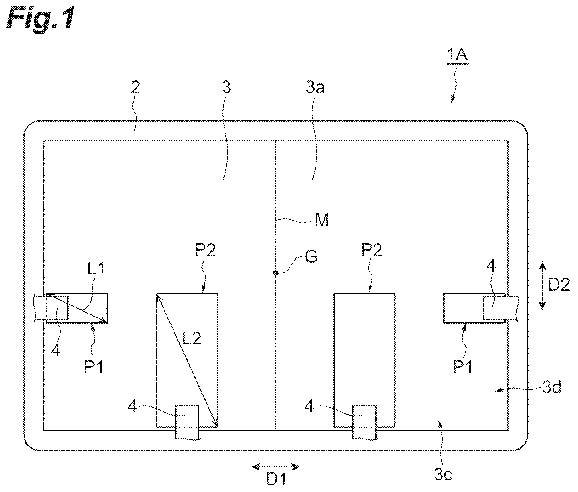
is a plan view of an audio device according to a first embodiment. is a cross-sectional view of the audio device in . As shown in , an audio device 1 A according to the first embodiment includes a restraint member 2 , a vibration member 3 , a pair of piezoelectric vibrators P 1 , and a pair of piezoelectric vibrators P 2 . Each piezoelectric vibrator P 1 and each piezoelectric vibrators P 2 have different natural frequencies from each other. The natural frequency varies depending on the shape, material, density, structure, stress, and the like of each of the piezoelectric vibrators P 1 and the piezoelectric vibrators P 2 . The density varies depending on not only the material but also the manufacturing method. The audio device 1 A generates sound by, for example, vibrating the vibration member 3 with the pair of piezoelectric vibrators P 1 and the pair of piezoelectric vibrators P 2 . The audio device 1 A is used as, for example, a speaker or a buzzer.
The restraint member 2 is, for example, a frame body having a rectangular shape and restrains an outer edge portion of the vibration member 3 . The restraint member 2 restrains the entire circumference of the outer edge portion. A step portion 2 a to which the outer edge portion is joined is formed at an inner edge portion of the restraint member 2 . The rectangular shape includes, for example, a rectangular shape in which each corner is chamfered and a rectangular shape in which each corner is rounded.
The vibration member 3 is, for example, a plate member having a rectangular shape. The vibration member 3 has flexibility. The vibration member 3 is made of, for example, resin, glass, or metal. The vibration member 3 has a pair of main faces 3 a and 3 b opposing each other. Each of the main faces 3 a and 3 b has a rectangular shape having a pair of long sides and a pair of short sides. The outer edge portion of the main face 3 b is joined to the step portion 2 a of the restraint member 2 . The outer edge portion of the main face 3 b is restrained while being supported by the step portion 2 a . The outer edge portion of the vibration member 3 has a pair of long side portions 3 c including the long sides of each of the main faces 3 a and 3 b and a pair of short side portions 3 d including the short sides of each of the main faces 3 a and 3 b.
In the following, the long-side direction of each of the main faces 3 a and 3 b is referred to as a first direction D 1 , the short-side direction is referred to as a second direction D 2 , and the opposing direction is referred to as a third direction D 3 . The third direction D 3 is also a direction orthogonal to each of the main faces 3 a and 3 b . The length of the vibration member 3 (the length of the vibration member 3 in the first direction D 1 ) is, for example, 240 mm. The width of the vibration member 3 (the length of the vibration member 3 in the second direction D 2 ) is, for example, 160 mm. The thickness of the vibration member 3 (the length of the vibration member 3 in the third direction D 3 ) is, for example, 1.05 mm.
is an exploded perspective view of each piezoelectric vibrator P 1 in . is a cross-sectional view of each piezoelectric vibrator P 1 in . As shown in , each piezoelectric vibrator P 1 includes a piezoelectric element body 11 and a plurality of (in this specification, three) external electrodes 13 , 14 , and 15 . Each piezoelectric vibrator P 1 is, for example, a bimorph piezoelectric element.
The piezoelectric element body 11 has a rectangular parallelepiped shape. The rectangular parallelepiped shape includes, for examples, a rectangular parallelepiped shape in which the corner portions and the ridge portions are chamfered and a rectangular parallelepiped shape in which the corner portions and the ridge portions are rounded. The piezoelectric element body 11 has a pair of main faces 11 a and 11 b opposing each other and four side faces 11 c connecting the main faces 11 a and 11 b to each other. The direction in which the main faces 11 a and 11 b face each other is aligned with the third direction D 3 .
Each of the main faces 11 a and 11 b has a rectangular shape having a pair of long sides and a pair of short sides. That is, each piezoelectric vibrator P 1 (piezoelectric element body 11 ) has a rectangular shape having a pair of long sides and a pair of short sides in plan view. The length of the piezoelectric element body 11 (the length of the piezoelectric element body 11 in the long-side direction of the main face 11 a ) is, for example, 30 mm. The width of the piezoelectric element body 11 (the length of the piezoelectric element body 11 in the short-side direction of the main face 11 a ) is, for example, 15 mm. The thickness of the piezoelectric element body 11 (the length of the piezoelectric element body 11 in the third direction D 3 ) is, for example, 0.7 mm.
The piezoelectric element body 11 includes a plurality of piezoelectric layers 17 a , 17 b , 17 c , and 17 d . The plurality of piezoelectric layers 17 a , 17 b , 17 c , and 17 d are laminated in this order. The laminating direction of the plurality of piezoelectric layers 17 a , 17 b , 17 c , and 17 d is aligned with the third direction D 3 . The piezoelectric layer 17 a has the main face 11 a . The piezoelectric layer 17 d has the main face 11 b . The piezoelectric layers 17 b and 17 c are positioned between the piezoelectric layer 17 a and the piezoelectric layer 17 d . In the present embodiment, the piezoelectric layers 17 a , 17 b , 17 c , and 17 d have an equal thickness. The term “equal” includes a manufacturing error range.
Each of the piezoelectric layers 17 a , 17 b , 17 c , and 17 d is made of a piezoelectric material. In the present embodiment, each of the piezoelectric layers 17 a , 17 b , 17 c , and 17 d is made of a piezoelectric ceramic material. As the piezoelectric ceramic material, PZT [Pb(Zr, Ti)O 3 ], PT (PbTiO 3 ), PLZT [(Pb, La)(Zr, Ti)O 3 ], or barium titanate (BaTiO 3 ) is used, for example. Each of the piezoelectric layers 17 a , 17 b , 17 c , and 17 d is made of, for example, a sintered body of a ceramic green sheet containing the above piezoelectric ceramic material. In the actual piezoelectric element body 11 , the piezoelectric layers 17 a , 17 b , 17 c , and 17 d are integrated in such a way that boundaries between the piezoelectric layers 17 a , 17 b , 17 c , and 17 d cannot be visually recognized.
Each of the external electrodes 13 , 14 , and 15 is disposed on the main face 11 a . The external electrodes 13 , 14 , and 15 are arranged on one short side of the main face 11 a in the order of the external electrode 13 , the external electrode 14 , and the external electrode 15 along the one short side. The external electrode 13 and the external electrode 14 are adjacent to each other in the short-side direction of the main face 11 a . The external electrode 14 and the external electrode 15 are adjacent to each other in the short-side direction of the main face 3 a . In the short-side direction of the main face 11 a , the distance (shortest distance) between the external electrode 14 and the external electrode 15 is longer than the distance (shortest distance) between the external electrode 13 and the external electrode 14 . Each of the external electrodes 13 , 14 , and 15 is separated from all the edges (four sides) of the main face 11 a when viewed from the third direction D 3 .
Each of the external electrodes 13 and 14 has a rectangular shape when viewed from the third direction D 3 . In the present embodiment, each corner of the rectangular shape is rounded. The external electrode 15 has a square shape when viewed from the third direction D 3 . The square shape includes, for example, a square shape in which each corner is chamfered and a square shape in which each corner is rounded. In the present embodiment, each corner of the square shape is rounded. Each of the external electrodes 13 , 14 , and 15 is made of a conductive material. As the conductive material, Ag, Pd, Pt, or an Ag—Pd alloy is used, for example. Each of the external electrodes 13 , 14 , and 15 is formed as, for example, a sintered body of a conductive paste containing the above conductive material.
Each piezoelectric vibrator P 1 includes a plurality of internal electrodes 21 , 22 , and 23 disposed in the piezoelectric element body 11 . Each of the internal electrodes 21 , 22 , and 23 is made of a conductive material. As the conductive material, Ag, Pd, Pt, or an Ag—Pd alloy is used, for example. Each of internal electrodes 21 , 22 , and 23 is formed as, for example, a sintered body of a conductive paste containing the above conductive material. In the present embodiment, the external shape of each of the internal electrodes 21 , 22 , and 23 is a rectangular shape.
The internal electrodes 21 , 22 , and 23 are disposed at different positions (layers) from each other in the third direction D 3 . The internal electrodes 21 , 22 , and 23 face each other with an interval in the third direction D 3 . The internal electrodes 21 , 22 , and 23 are not exposed on the surface of the piezoelectric element body 11 . That is, the internal electrodes 21 , 22 , and 23 are not exposed on each side face 11 c . Each of the internal electrodes 21 , 22 , and 23 is separated from all edges (four sides) of the main faces 11 a and 11 b when viewed from the third direction D 3 .
The internal electrode 21 is positioned between the piezoelectric layer 17 a and the piezoelectric layer 17 b . The internal electrode 22 is positioned between the piezoelectric layer 17 b and the piezoelectric layer 17 c . The internal electrode 23 is positioned between the piezoelectric layer 17 c and the piezoelectric layer 17 d.
The external electrode 13 is electrically connected to the internal electrode 21 and a plurality of connection conductors 33 through a plurality of via conductors 43 . The plurality of connection conductors 33 are positioned in the same layers as the internal electrodes 22 and 23 . Specifically, each connection conductor 33 is positioned in an opening formed in each of the internal electrodes 22 and 23 . Each opening is formed at a position corresponding to the external electrode 13 when viewed from the third direction D 3 . That is, each connection conductor 33 is surrounded by each of the internal electrodes 22 and 23 when viewed from the third direction D 3 . Each connection conductor 33 is separated from each of the internal electrodes 22 and 23 .
Each connection conductor 33 faces the external electrode 13 in the third direction D 3 and is disposed at a position overlapping the external electrode 13 when viewed from the third direction D 3 . Each connection conductor 33 faces the internal electrode 21 in the third direction D 3 and is disposed at a position overlapping the internal electrode 21 when viewed from the third direction D 3 . Each of the plurality of via conductors 43 is positioned between the external electrode 13 , the internal electrode 21 , and the plurality of connection conductors 33 and is disposed at a position overlapping the external electrode 13 when viewed from the third direction D 3 . Each of the plurality of via conductors 43 passes through the corresponding piezoelectric layer 17 a , 17 b , or 17 c in the third direction D 3 .
The external electrode 14 is electrically connected to the internal electrode 23 and a plurality of connection conductors 34 through a plurality of via conductors 44 . The plurality of connection conductors 34 are positioned in the same layers as the internal electrodes 21 and 22 . Specifically, each connection conductor 34 is positioned in an opening formed in each of the internal electrodes 21 and 22 . Each opening is formed at a position corresponding to the external electrode 14 when viewed from the third direction D 3 . That is, each connection conductor 34 is surrounded by each of the internal electrodes 21 and 22 when viewed from the third direction D 3 . Each connection conductor 34 is separated from each of the internal electrodes 21 and 22 . The connection conductor 33 and the connection conductor 34 positioned in the same layer as the internal electrode 22 are disposed adjacent to each other in the same opening and are separated from each other.
Each connection conductor 34 faces the external electrode 14 in the third direction D 3 and is disposed at a position overlapping the external electrode 14 when viewed from the third direction D 3 . Each connection conductor 34 faces the internal electrode 23 in the third direction D 3 and is disposed at a position overlapping the internal electrode 23 when viewed from the third direction D 3 . Each of the plurality of via conductors 44 is positioned between the external electrode 14 , the internal electrode 23 , and the plurality of connection conductors 34 and is disposed at a position overlapping the external electrode 14 when viewed from the third direction D 3 . Each of the plurality of via conductors 44 passes through the corresponding piezoelectric layer 17 a , 17 b , or 17 c in the third direction D 3 .
The external electrode 15 is electrically connected to the internal electrode 22 and a plurality of connection conductors 35 through a plurality of via conductors 45 . The plurality of connection conductors 35 are positioned in the same layers as the internal electrodes 21 and 23 . Specifically, each connection conductor 35 is positioned in an opening formed in each of the internal electrodes 21 and 23 . Each opening is formed at a position corresponding to the external electrode 15 when viewed from the third direction D 3 . That is, the entire edge of each connection conductor 35 is surrounded by each of the internal electrodes 21 and 23 when viewed from the third direction D 3 . Each opening is formed at a position corresponding to the external electrode 15 when viewed from the third direction D 3 .
Each connection conductor 35 faces the external electrode 15 in the third direction D 3 and is disposed at a position overlapping the external electrode 15 when viewed from the third direction D 3 . Each connection conductor 35 faces the internal electrode 22 in the third direction D 3 and is disposed at a position overlapping the internal electrode 22 when viewed from the third direction D 3 . Each of the plurality of via conductors 45 is positioned between the external electrode 15 , the internal electrode 22 , and the plurality of connection conductors 35 and is disposed at a position overlapping the external electrode 15 when viewed from the third direction D 3 . Each of the plurality of via conductors 45 passes through the corresponding piezoelectric layer 17 a , 17 b , or 17 c in the third direction D 3 .
Each of the connection conductors 33 and 34 has a rectangular shape when viewed from the third direction D 3 . In the present embodiment, each corner of the rectangular shape is rounded. Each connection conductor 35 has a square shape when viewed from the third direction D 3 . In the present embodiment, each corner of the square shape is rounded.
The connection conductors 33 , 34 , and 35 and the via conductors 43 , 44 , and 45 are made of a conductive material. As the conductive material, Ag, Pd, Pt, or an Ag—Pd alloy is used, for example. The connection conductors 33 , 34 , and 35 and the via conductors 43 , 44 , and 45 are formed as, for example, sintered bodies of a conductive paste containing the above conductive material. The via conductors 43 , 44 , and 45 are formed by sintering the conductive paste filled in a through hole formed in a ceramic green sheet for forming the corresponding piezoelectric layers 17 a , 17 b , and 17 c.
On the main face 11 b of the piezoelectric element body 11 , no conductor electrically connected to the internal electrodes 21 , 22 , and 23 is disposed. In the present embodiment, when the main face 11 b is viewed from the third direction D 3 , the entire main face 11 b is exposed. The main faces 11 a and 11 b are natural faces. The natural face is a surface constituted by surfaces of crystal grains grown by firing.
On each side face 11 c of the piezoelectric element body 11 , no conductor electrically connected to the internal electrodes 21 , 22 , and 23 is disposed either. In the present embodiment, when each side face 11 c is viewed from the direction intersecting the third direction D 3 , the entire side face 11 c is exposed. In the present embodiment, each side face 11 c is also a natural face.
In the piezoelectric layer 17 b , a region sandwiched between the internal electrode 21 connected to the external electrode 13 and the internal electrode 22 connected to the external electrode 15 constitutes a first active region 19 that is piezoelectrically active. In the piezoelectric layers 17 c , a region sandwiched between the internal electrode 23 connected to the external electrode 14 and the internal electrode 22 connected to the external electrode 15 constitutes a second active region 20 that is piezoelectrically active. The first active region 19 and the second active region 20 are disposed between the main face 11 a and the main face 11 b . The second active region 20 is disposed closer to the main face 11 b than the first active region 19 . The first active region 19 and the second active region 20 may be constituted by a plurality of piezoelectric layers.
In the present embodiment, the first active region 19 and the second active region 20 are positioned in such a way as to surround the plurality of external electrodes 13 , 14 , and 15 when viewed from the third direction D 3 . The first active region 19 and the second active region 20 include a region positioned between the external electrode 14 and the external electrode 15 when viewed from the third direction D 3 and a region outside the region in which the external electrodes 13 , 14 , and 15 are positioned when viewed from the third direction D 3 .
The first active region 19 and the second active region 20 are polarized in the same direction by, for example, applying, to the external electrode 15 and the external electrode 13 , voltages having different polarities from each other while the external electrode 14 is being connected to the ground. The first active region 19 is polarized in, for example, a direction from the internal electrode 21 toward the internal electrode 22 , and the second active region 20 is polarized in, for example, a direction from the internal electrode 22 toward the internal electrode 23 . When each piezoelectric vibrator P 1 is driven, for example, a voltage having the same polarity is applied to the external electrodes 13 and 14 , and a voltage having a different polarity from that applied to the external electrodes 13 and 14 is applied to the external electrode 15 . Accordingly, a voltage in the same direction (forward direction) as the polarization direction is applied to one of the first active region 19 and the second active region 20 to elongate the one, and a voltage in the opposite direction (reverse direction) to the polarization direction is applied to the other to contract the other. As a result, each piezoelectric vibrator P 1 bends and vibrates.
Each piezoelectric vibrator P 2 shown in is, for example, a bimorph piezoelectric element. Although not shown, each piezoelectric vibrator P 2 includes, similarly to each piezoelectric vibrator P 1 , a piezoelectric element body 11 , external electrodes 13 , 14 , and 15 , internal electrodes 21 , 22 , and 23 , connection conductors 33 , 34 , and 35 , and via conductors 43 , 44 , and 45 as shown in . Each piezoelectric vibrator P 2 is different from each piezoelectric vibrator P 1 mainly in the shapes of the piezoelectric element body 11 and the internal electrodes 21 , 22 , and 23 viewed from the third direction D 3 . The length and width of the piezoelectric element body 11 of each piezoelectric vibrator P 2 are larger than the length and width of the piezoelectric element body 11 of each piezoelectric vibrator P 1 .
The length of the piezoelectric element body 11 of each piezoelectric vibrator P 2 (the length of the piezoelectric element body 11 in the long-side direction of the main face 11 a ) is, for example, 66 mm. The width of the piezoelectric element body 11 of each piezoelectric vibrator P 2 (the length of the piezoelectric element body 11 in the short-side direction of the main face 11 a ) is, for example, 30 mm. The thickness of the piezoelectric element body 11 of each piezoelectric vibrator P 2 is equal to the thickness of the piezoelectric element body 11 of each piezoelectric vibrator P 1 . That is, the thickness of the piezoelectric element body 11 of each piezoelectric vibrator P 2 (the length of the piezoelectric element body 11 in the third direction D 3 ) is, for example, 0.7 mm. The internal electrodes 21 , 22 , and 23 of each piezoelectric vibrator P 2 each have a shape matching the shape of the piezoelectric element body 11 of the piezoelectric vibrator P 2 . The shapes of the external electrodes 13 , 14 , and 15 , of the connection conductors 33 , 34 , and 35 , and of the via conductors 43 , 44 , and 45 and a relative positional relation between them are equal between each piezoelectric vibrator P 2 and each piezoelectric vibrator P 1 .
When viewed from the third direction D 3 , a maximum length L 1 of each piezoelectric vibrator P 1 is shorter than a maximum length L 2 of each piezoelectric vibrator P 2 . In the present embodiment, each of the main faces 11 a and 11 b of each piezoelectric vibrator P 1 has a rectangular shape, and the maximum length L 1 is a length of a diagonal line of each of the main faces 11 a and 11 b of the piezoelectric vibrator P 1 , and is, for example, 34 mm. Each of the main faces 11 a and 11 b of each piezoelectric vibrator P 2 also has a rectangular shape, and the maximum length L 2 is a length of a diagonal line of each of the main faces 11 a and 11 b of the piezoelectric vibrator P 2 , and is, for example, 73 mm.
The pair of piezoelectric vibrators P 1 and the pair of piezoelectric vibrators P 2 are provided on the vibration member 3 . Each piezoelectric vibrator P 1 and each piezoelectric vibrator P 2 are fixed to the vibration member 3 by, for example, bonding each main face 11 b to the main face 3 a with a bonding member (not shown). The pair of piezoelectric vibrators P 1 and the pair of piezoelectric vibrators P 2 are disposed to be separated from each other.
When viewed from the third direction D 3 , one of the pair of piezoelectric vibrators P 1 is provided in a left region of a straight line M that passes through a gravity center G of the main face 3 a and is parallel to the second direction D 2 , and the other is provided in a right region. The pair of piezoelectric vibrators P 1 is disposed in such a way as to be line-symmetric with respect to the straight line M when viewed from the third direction D 3 . Each piezoelectric vibrator P 1 is disposed in such a way that the long-side direction of the main face 11 a is aligned with the first direction D 1 and that the short-side direction of the main face 11 a is aligned with the second direction D 2 . When viewed from the third direction D 3 , the piezoelectric vibrators P 1 are disposed to be separated from each other in the first direction D 1 . At least a part of each piezoelectric vibrator P 1 is disposed in each short side portion 3 d . Specifically, one end portion of each piezoelectric vibrator P 1 in the long-side direction of the main face 11 a is disposed in each short side portion 3 d . Each piezoelectric vibrator P 1 is disposed to be separated from the pair of long side portions 3 c.
When viewed from the third direction D 3 , one of the pair of piezoelectric vibrators P 2 is provided in the left region of the straight line M, and the other is provided in the right region. The pair of piezoelectric vibrators P 2 is disposed in such a way as to be line-symmetric with respect to the straight line M when viewed from the third direction D 3 . Each piezoelectric vibrator P 2 is disposed in such a way that the long-side direction of the main face 11 a is aligned with the second direction D 2 and that the short-side direction of the main face 11 a is aligned with the first direction D 1 . When viewed from the third direction D 3 , the piezoelectric vibrators P 2 are disposed to be separated from each other in the first direction D 1 . At least a part of each piezoelectric vibrator P 2 is disposed in one long side portion 3 c . Specifically, one end portion of each piezoelectric vibrator P 2 in the long-side direction of the main face 11 a is disposed in one long side portion 3 c . Each piezoelectric vibrator P 2 is disposed to be separated from the other long side portion 3 c and the pair of short side portions 3 d.
When viewed from the third direction D 3 , each piezoelectric vibrator P 2 is disposed closer to the straight line M than each piezoelectric vibrator P 1 . When viewed from the third direction D 3 , each piezoelectric vibrator P 2 is disposed closer to the gravity center G than each piezoelectric vibrator P 1 . When viewed from the third direction D 3 , the distance (shortest distance) between each piezoelectric vibrator P 1 and each piezoelectric vibrator P 2 is shorter than the maximum length L 2 of the piezoelectric vibrator P 2 .
Each piezoelectric vibrator P 1 and each piezoelectric vibrator P 2 are each connected to a wiring member 4 . The wiring member 4 is, for example, a flexible printed circuit board (FPC) or a flexible flat cable (FFC). One end portion of the wiring member 4 is disposed on the external electrodes 13 , 14 , and 15 and connected to the external electrodes 13 , 14 , and 15 . The wiring member 4 has, for example, a first conductor layer (not shown) connected to the external electrodes 13 and 14 and a second conductor layer (not shown) connected to the external electrode 15 . The external electrodes 13 and 14 are short-circuited by the first conductor layer.
The wiring member 4 is drawn out to the restraint member 2 . The other end portion of the wiring member 4 is connected to a control circuit (not shown) that controls the audio device 1 A. The control circuit includes, for example, a central processing unit (CPU), a read only memory (ROM), and a random access memory (RAM). In this case, the control circuit loads a program stored in the ROM into the RAM and executes the program by the CPU to perform various processes. The control circuit inputs the same drive signal to each piezoelectric vibrator P 1 and each piezoelectric vibrator P 2 . That is, each piezoelectric vibrator P 1 and each piezoelectric vibrator P 2 are synchronously driven by the same drive signal.
As described above, in the audio device 1 A, the natural frequency of each piezoelectric vibrator P 1 is larger than the natural frequency of each piezoelectric vibrator P 2 . Thus, each piezoelectric vibrator P 1 can improve sound quality (sound pressure) in a high range (high frequency range) as compared with each piezoelectric vibrator P 2 , and each piezoelectric vibrator P 2 can improve sound quality in a low range (low frequency range) as compared with each piezoelectric vibrator P 1 . Accordingly, the audio device 1 A can improve sound quality in a wide range (frequency range) while achieving downsizing. That is, the audio device 1 A can equalize the sound quality in the entire range (entire frequency range) while achieving downsizing.
When viewed from the third direction D 3 , a maximum length L 1 of each piezoelectric vibrator P 1 is shorter than a maximum length L 2 of each piezoelectric vibrator P 2 . Thus, it is possible to easily implement each piezoelectric vibrator P 1 having a larger natural frequency than the natural frequency of each piezoelectric vibrator P 2 .
In order to improve sound quality in a wide range, it is conceivable to drive each piezoelectric vibrator P 1 and each piezoelectric vibrator P 2 with different drive signals, but the configuration of the control circuit becomes complicated in that case. In the audio device 1 A, each piezoelectric vibrator P 1 and each piezoelectric vibrator P 2 are synchronously driven by the same drive signal, and it is possible to improve sound quality in a wide range while the configuration of the control circuit is prevented from being complicated.
When viewed from the third direction D 3 , the distance (shortest distance) between each piezoelectric vibrator P 1 and each piezoelectric vibrator P 2 is shorter than the maximum length L 2 of the piezoelectric vibrator P 2 . As described above, each piezoelectric vibrator P 1 and each piezoelectric vibrator P 2 are disposed close to each other, and a phase difference hardly occurs. Accordingly, the connection between the sound of each piezoelectric vibrator P 1 and the sound of each piezoelectric vibrator P 2 is improved.
Second Embodiment
is a plan view of an audio device according to a second embodiment. As shown in , an audio device 1 B according to the second embodiment is different from the audio device 1 A in that the arrangement of piezoelectric vibrators P 2 is different and is the same as the audio device 1 A in other points. That is, the audio device 1 B also includes a pair of piezoelectric vibrators P 1 and a pair of piezoelectric vibrators P 2 having different natural frequencies and can improve sound quality in a wide range while achieving downsizing.
Each piezoelectric vibrator P 2 is disposed closer to one long side portion 3 c than a straight line that passes through the gravity center G and is parallel to the first direction D 1 . In each piezoelectric vibrator P 2 , the long-side direction of the main face 11 a is not aligned with the first direction D 1 , and the long-side direction of the main face 11 a is inclined with respect to the first direction D 1 in such a way that, of both end portions of the piezoelectric vibrator P 2 in the long-side direction of the main face 11 a , one end portion having a longer distance (shortest distance) from the restraint member 2 is closer to the straight line M than the end portion having a shorter distance (shortest distance) from the restraint member 2 . Accordingly, the end portion, which has a longer distance from the restraint member 2 , of each piezoelectric vibrator P 2 is hardly affected by the restraint force from the restraint member 2 and can efficiently transmit vibration to the vicinity of the gravity center G. Thus, in the audio device 1 B, each piezoelectric vibrator P 2 can further improve sound quality in a low range.
Third Embodiment
is a plan view of an audio device according to a third embodiment. As shown in , an audio device 1 C according to the third embodiment is different from the audio device 1 A mainly in including a pair of piezoelectric vibrators P 3 . The natural frequency of each piezoelectric vibrator P 3 is larger than the natural frequency of each piezoelectric vibrator P 2 and smaller than the natural frequency of each piezoelectric vibrator P 1 .
Each piezoelectric vibrator P 3 is, for example, a bimorph piezoelectric element. Although not shown, each piezoelectric vibrator P 3 includes, similarly to each piezoelectric vibrator P 1 , a piezoelectric element body 11 , external electrodes 13 , 14 , and 15 , internal electrodes 21 , 22 , and 23 , connection conductors 33 , 34 , and 35 , and via conductors 43 , 44 , and 45 as shown in . Each piezoelectric vibrator P 3 is different from each piezoelectric vibrator P 1 mainly in the shapes of the piezoelectric element body 11 and the internal electrodes 21 , 22 , and 23 viewed from the third direction D 3 . Each of the main faces 11 a and 11 b of the piezoelectric element body 11 of each piezoelectric vibrator P 3 has a square shape. The length of one side of each of the main faces 11 a and 11 b of each piezoelectric vibrator P 3 is, for example, 30 mm. The thickness of the piezoelectric element body 11 of each piezoelectric vibrator P 3 (the length of the piezoelectric element body 11 in the third direction D 3 ) is, for example, 0.5 mm.
The internal electrodes 21 , 22 , and 23 of each piezoelectric vibrator P 3 each have a shape matching the shape of the piezoelectric element body 11 of the piezoelectric vibrator P 3 . The external electrodes 13 , 14 , and 15 of each piezoelectric vibrator P 3 are arranged on one side of the main face 11 a along the one side. The shapes of the external electrodes 13 , 14 , and 15 , of the connection conductors 33 , 34 , and 35 , and of the via conductors 43 , 44 , and 45 , and a relative positional relation between them are equal between each piezoelectric vibrator P 3 and each piezoelectric vibrator P 1 .
When viewed from the third direction D 3 , a maximum length L 3 of each piezoelectric vibrator P 3 is longer than the maximum length L 1 of each piezoelectric vibrator P 1 and shorter than the maximum length L 2 of each piezoelectric vibrator P 2 . In the present embodiment, each of the main faces 11 a and 11 b of each piezoelectric vibrator P 3 has a square shape, and the maximum length L 3 is a length of a diagonal line of each of the main faces 11 a and 11 b of the piezoelectric vibrator P 3 , and is, for example, 42 mm.
When viewed from the third direction D 3 , one of the pair of piezoelectric vibrators P 3 is provided in the left region of the straight line M, and the other is provided in the right region. The pair of piezoelectric vibrators P 3 is disposed in such a way as to be line-symmetric with respect to the straight line M when viewed from the third direction D 3 . Each piezoelectric vibrator P 3 is disposed in such a way that one side of a pair of sides adjacent to each other of the main face 11 a is parallel to the first direction D 1 and the other side is aligned with the second direction D 2 . When viewed from the third direction D 3 , the piezoelectric vibrators P 3 are disposed to be separated from each other in the first direction D 1 . At least a part of each piezoelectric vibrator P 3 is disposed in one long side portion 3 c . Specifically, one end portion of the main face 11 a in the second direction D 2 is disposed in one long side portion 3 c . Each piezoelectric vibrator P 3 is disposed to be separated from the other long side portion 3 c and the pair of short side portions 3 d.
When viewed from the third direction D 3 , each piezoelectric vibrator P 3 is disposed to be separated farther from the straight line M than each piezoelectric vibrator P 2 . When viewed from the third direction D 3 , the distance (shortest distance) between each piezoelectric vibrator P 3 and the straight line M is longer than the distance (shortest distance) between each piezoelectric vibrator P 2 and the straight line M. Similarly to each piezoelectric vibrator P 1 and each piezoelectric vibrator P 2 , each piezoelectric vibrator P 3 is connected to a wiring member 4 . The wiring member 4 is drawn out to the restraint member 2 . Each piezoelectric vibrator P 3 is synchronously driven by the same drive signal as each piezoelectric vibrator P 1 and each piezoelectric vibrator P 2 .
The audio device 1 C further includes the piezoelectric vibrators P 3 having a natural frequency smaller than the natural frequency of the piezoelectric vibrators P 1 and larger than the natural frequency of the piezoelectric vibrators P 2 . Thus, the piezoelectric vibrator P 3 can improve sound quality in an intermediate range between a high range and a low range. Accordingly, it is possible to improve sound quality in a wider range while downsizing is achieved.
Fourth Embodiment
is a plan view of an audio device according to a fourth embodiment. As shown in , an audio device 1 D according to the fourth embodiment is different from the audio device 1 C in the number and arrangement of piezoelectric vibrators P 2 and is the same as the audio device 1 C in other points. That is, the audio device 1 D also includes a pair of piezoelectric vibrators P 1 , a piezoelectric vibrator P 2 , and a pair of piezoelectric vibrators P 3 having different natural frequencies and can improve sound quality in a wider range while achieving downsizing.
The audio device 1 D includes the single piezoelectric vibrator P 2 . The piezoelectric vibrator P 2 is disposed in such a way that the gravity center of the main face 11 a of the piezoelectric vibrator P 2 overlaps the straight line M when viewed from the third direction D 3 . That is, when viewed from the third direction D 3 , the piezoelectric vibrator P 2 is bisected in the short-side direction of the main face 11 a by the straight line M, and one half is arranged in the left region of the straight line M and the other half is arranged in the right region.
In the audio device 1 D, the number of piezoelectric vibrators is fewer than those in the audio device 1 C, and it is difficult to improve sound quality in a low range. However, in the low range, the difference between the left region and the right region of the straight line M is difficult to recognize. Thus, according to the audio device 1 D, it is possible to simplify the configuration without significantly affecting the sound quality. Accordingly, space saving can be also achieved, for example.
Fifth Embodiment
is a plan view of an audio device according to a fifth embodiment. As shown in , an audio device 1 E according to the fifth embodiment is different from the audio device 1 A in that the arrangement of piezoelectric vibrators P 1 is different and is the same as the audio device 1 A in other points. That is, the audio device 1 E also includes a pair of piezoelectric vibrators P 1 and a pair of piezoelectric vibrators P 2 having different natural frequencies and can improve sound quality in a wide range while achieving downsizing.
In the audio device 1 E, each piezoelectric vibrator P 1 is disposed in such a way that the long-side direction of the main face 11 a is aligned with the second direction D 2 and that the short-side direction of the main face 11 a is aligned with the first direction D 1 . In addition, each piezoelectric vibrator P 1 is disposed to be separated from the long side portions 3 c and the short side portions 3 d . When viewed from the third direction D 3 , the distance (shortest distance) between each piezoelectric vibrator P 1 and the restraint member 2 is longer than the distance (shortest distance) between each piezoelectric vibrator P 2 and the restraint member 2 .
is a diagram for explaining displacement of a vibration member. In , the displacement of the vibration member 3 when each piezoelectric vibrator P 1 is disposed near the restraint member 2 is indicated by a solid line, and the displacement of the vibration member 3 when each piezoelectric vibrator P 1 is disposed near the gravity center G of the vibration member 3 is indicated by a broken line. In either case, the magnitude of the drive signal (voltage) applied to each piezoelectric vibrator P 1 is the same. Thus, although the displacement of each piezoelectric vibrator P 1 is the same, a difference occurs in the displacement of the vibration member 3 depending on the position of the piezoelectric vibrator P 1 . As each piezoelectric vibrator P 1 is closer to the restraint member 2 , one end of the piezoelectric vibrator P 1 is more easily fixed. As the result, the displacement increases in a low range, and the followability deteriorates in a high range. In contrast, as each piezoelectric vibrator P 1 is closer to the gravity center G, the displacement decreases in the low range, and the followability is improved in the high range. Although shows a case where the piezoelectric vibrator P 1 is disposed on the main face 3 b (see ), a similar difference occurs in the displacement of the vibration member 3 depending on the position of the piezoelectric vibrator P 1 if the piezoelectric vibrator P 1 is disposed on the main face 3 a (see ).
As described above, in the audio device 1 E, each piezoelectric vibrator P 1 is disposed to be separated from the long side portions 3 c and the short side portions 3 d , and the distance (shortest distance) between each piezoelectric vibrator P 1 and the restraint member 2 is longer than the distance (shortest distance) between each piezoelectric vibrator P 2 and the restraint member 2 when viewed from the third direction D 3 . Since each piezoelectric vibrator P 1 has a relatively long distance to the restraint member 2 and can further improve sound quality in a high range. Since each piezoelectric vibrator P 2 has a relatively short distance to the restraint member 2 and can further improve sound quality in a low range. Accordingly, it is possible to further improve sound quality in a wide range.
Sixth Embodiment
is a plan view of an audio device according to a sixth embodiment. As shown in , an audio device 1 F according to the sixth embodiment is different from the audio device 1 A in that the arrangement of piezoelectric vibrators P 1 and piezoelectric vibrators P 2 is different and is the same as the audio device 1 A in other points. That is, the audio device 1 F also includes a pair of piezoelectric vibrators P 1 and a pair of piezoelectric vibrators P 2 having different natural frequencies and can improve sound quality in a wide range while achieving downsizing.
In the audio device 1 F, each piezoelectric vibrator P 1 is separated from the short side portions 3 d , and each piezoelectric vibrator P 2 is separated from the long side portions 3 c . As described with reference to , as each piezoelectric vibrator P 1 is closer to the gravity center G, the displacement decreases in a low range, and the followability is improved in a high range. Similarly, as each piezoelectric vibrator P 2 is closer to the gravity center G, the displacement decreases in a low range, and the followability is improved in a high range. Thus, according to the audio device 1 F, it is possible to further improve sound quality in a higher range than the audio device 1 E does.
Seventh Embodiment
is a plan view of an audio device according to a seventh embodiment. As shown in , an audio device 1 G according to the seventh embodiment is different from the audio device 1 A in that a pair of piezoelectric vibrators P 4 is provided instead of the pair of piezoelectric vibrators P 1 and that the number and arrangement of piezoelectric vibrators P 2 are different and is the same as the audio device 1 A in other points. The natural frequency of each piezoelectric vibrator P 4 is larger than the natural frequency of each piezoelectric vibrator P 1 .
Each piezoelectric vibrator P 4 is, for example, a bimorph piezoelectric element. Although not shown, each piezoelectric vibrator P 4 includes, similarly to each piezoelectric vibrator P 1 , a piezoelectric element body 11 , external electrodes 13 , 14 , and 15 , internal electrodes 21 , 22 , and 23 , connection conductors 33 , 34 , and 35 , and via conductors 43 , 44 , and 45 as shown in . Each piezoelectric vibrator P 4 is different from each piezoelectric vibrator P 1 mainly in the shapes of the piezoelectric element body 11 and the internal electrodes 21 , 22 , and 23 viewed from the third direction D 3 . Each of the main faces 11 a and 11 b of the piezoelectric element body 11 of each piezoelectric vibrator P 4 has an elliptical shape. The length of the major axis of each of the main faces 11 a and 11 b of each piezoelectric vibrator P 4 is, for example, 30 mm, and the length of the minor axis is, for example, 15 mm. The thickness of the piezoelectric element body 11 of each piezoelectric vibrator P 4 is equal to the thickness of the piezoelectric element body 11 of each piezoelectric vibrator P 1 . That is, the thickness of the piezoelectric element body 11 of each piezoelectric vibrator P 4 (the length of the piezoelectric element body 11 in the third direction D 3 ) is, for example, 0.7 mm.
The internal electrodes 21 , 22 , and 23 of each piezoelectric vibrator P 4 each have a shape matching the shape of the piezoelectric element body 11 of the piezoelectric vibrator P 4 . The external electrodes 13 , 14 , and 15 of each piezoelectric vibrator P 4 are disposed on one end side in the minor-axis direction of the main face 11 a and are arranged along the major-axis direction of the main face 11 a . The shapes of the external electrodes 13 , 14 , and 15 , of the connection conductors 33 , 34 , and 35 , and of the via conductors 43 , 44 , and 45 , and a relative positional relation between them are equal between each piezoelectric vibrator P 4 and each piezoelectric vibrator P 1 .
When viewed from the third direction D 3 , a maximum length L 4 of each piezoelectric vibrator P 4 is shorter than the maximum length L 1 of each piezoelectric vibrator P 1 . In the present embodiment, each of the main faces 11 a and 11 b of each piezoelectric vibrator P 4 has an elliptical shape, and the maximum length L 4 is the length of the major axis of each of the main faces 11 a and 11 b of the piezoelectric vibrator P 4 .
When viewed from the third direction D 3 , one of the pair of piezoelectric vibrators P 4 is provided in the left region of the straight line M, and the other is provided in the right region. The pair of piezoelectric vibrators P 4 is disposed in such a way as to be line-symmetric with respect to the straight line M when viewed from the third direction D 3 . Each piezoelectric vibrator P 4 is disposed in such a way that the major-axis direction of the main face 11 a is aligned with the first direction D 1 and that the minor-axis direction of the main face 11 a is aligned with the second direction D 2 . When viewed from the third direction D 3 , the piezoelectric vibrators P 4 are disposed to be separated from each other in the first direction D 1 . At least a part of each piezoelectric vibrator P 4 is disposed in the short side portion 3 d . Specifically, one end portion of the main face 11 a in the major-axis direction is disposed in each short side portion 3 d . Each piezoelectric vibrator P 4 is disposed to be separated from the pair of long side portions 3 c.
When viewed from the third direction D 3 , each piezoelectric vibrator P 4 is disposed to be separated farther from the straight line M than the piezoelectric vibrator P 2 . Similarly to the piezoelectric vibrator P 2 , each piezoelectric vibrator P 4 is connected to a wiring member 4 . Each piezoelectric vibrator P 4 is synchronously driven by the same drive signal as the piezoelectric vibrator P 2 .
The audio device 1 G includes the single piezoelectric vibrator P 2 . The piezoelectric vibrator P 2 is disposed in such a way that the gravity center of the main face 11 a of the piezoelectric vibrator P 2 overlaps the straight line M when viewed from the third direction D 3 . That is, the piezoelectric vibrator P 2 is bisected in the short-side direction of the main face 11 a by the straight line M when viewed from the third direction D 3 , and one half is arranged in the left region of the straight line M and the other half is arranged in the right region when viewed from the third direction D 3 .
The audio device 1 G also includes the piezoelectric vibrators P 2 and the piezoelectric vibrators P 4 having different natural frequencies and can improve sound quality in a wide range while achieving downsizing. In addition, in the audio device 1 G, the number of piezoelectric vibrators P 2 is fewer than those in the audio device 1 A, and it is difficult to improve sound quality in a low range. However, in the low range, the difference between the left region and the right region of the straight line M is difficult to recognize. Thus, according to the audio device 1 G, it is possible to simplify the configuration without significantly affecting the sound quality. Accordingly, space saving can be also achieved, for example.
Eighth Embodiment
is a plan view of an audio device according to an eighth embodiment. As shown in , an audio device 1 H according to the eighth embodiment is different from the audio device 1 A in including a pair of piezoelectric vibrators P 3 instead of the pair of piezoelectric vibrators P 2 and is the same as the audio device 1 A in other points. That is, the audio device 1 H also includes a pair of piezoelectric vibrators P 1 and a pair of piezoelectric vibrators P 3 having different natural frequencies and can improve sound quality in a wide range while achieving downsizing.
When viewed from the third direction D 3 , one of the pair of piezoelectric vibrators P 3 is provided in the left region of the straight line M, and the other is provided in the right region. The pair of piezoelectric vibrators P 3 is disposed in such a way as to be line-symmetric with respect to the straight line M when viewed from the third direction D 3 . Each piezoelectric vibrator P 3 is disposed in such a way that one side of a pair of sides adjacent to each other of the main face 11 a is parallel to the first direction D 1 and the other side is aligned with the second direction D 2 . When viewed from the third direction D 3 , the piezoelectric vibrators P 3 are disposed to be separated from each other in the first direction D 1 . At least a part of each piezoelectric vibrator P 3 is disposed in one long side portion 3 c . Specifically, one end portion of the main face 11 a in the second direction D 2 is disposed in one long side portion 3 c . Each piezoelectric vibrator P 3 is disposed to be separated from the other long side portion 3 c and the pair of short side portions 3 d.
When viewed from the third direction D 3 , each piezoelectric vibrator P 3 is disposed closer to the straight line M than each piezoelectric vibrator P 1 . When viewed from the third direction D 3 , the distance (shortest distance) between each piezoelectric vibrator P 3 and the straight line M is shorter than the distance (shortest distance) between each piezoelectric vibrator P 1 and the straight line M. Each piezoelectric vibrator P 3 is connected to a wiring member 4 . The wiring member 4 is drawn out to the restraint member 2 . Each piezoelectric vibrator P 3 is synchronously driven by the same drive signal as each piezoelectric vibrator P 1 .
The audio device 1 H includes the piezoelectric vibrators P 3 having a natural frequency larger than the natural frequency of the piezoelectric vibrators P 2 . Thus, the audio device 1 H can improve sound quality in a higher range than the audio device 1 A does.
In the audio device 1 H, when viewed from the third direction D 3 , the distance (shortest distance) between each piezoelectric vibrator P 1 and each piezoelectric vibrator P 3 is longer than the maximum length L 3 of the piezoelectric vibrator P 3 . As described above, each piezoelectric vibrator P 1 and each piezoelectric vibrator P 3 are not disposed close to each other, and it is possible for the sound of each piezoelectric vibrator P 1 and the sound of each piezoelectric vibrator P 3 to be independent sounds.
Ninth Embodiment
is a plan view of an audio device according to a ninth embodiment. As shown in , an audio device 1 I according to the ninth embodiment is different from the audio device 1 H in that a pair of piezoelectric vibrators P 5 is provided instead of the pair of piezoelectric vibrators P 3 and that the arrangement of piezoelectric vibrators P 1 is different and is the same as the audio device 1 H in other points. The natural frequency of each piezoelectric vibrator P 5 is larger than the natural frequencies of each piezoelectric vibrator P 3 and each piezoelectric vibrator P 1 .
Each piezoelectric vibrator P 5 is, for example, a bimorph piezoelectric element. Although not shown, each piezoelectric vibrator P 5 includes, similarly to each piezoelectric vibrator P 1 , a piezoelectric element body 11 , external electrodes 13 , 14 , and 15 , internal electrodes 21 , 22 , and 23 , connection conductors 33 , 34 , and 35 , and via conductors 43 , 44 , and 45 as shown in . Each piezoelectric vibrator P 5 is different from each piezoelectric vibrator P 1 mainly in the shapes of the piezoelectric element body 11 and the internal electrodes 21 , 22 , and 23 viewed from the third direction D 3 . Each of the main faces 11 a and 11 b of the piezoelectric element body 11 of each piezoelectric vibrator P 5 has a circular shape. The diameter of each of the main faces 11 a and 11 b of each piezoelectric vibrator P 5 is, for example, 30 mm. The thickness of the piezoelectric element body 11 of each piezoelectric vibrator P 5 is equal to the thickness of the piezoelectric element body 11 of each piezoelectric vibrator P 1 . That is, the thickness of the piezoelectric element body 11 of each piezoelectric vibrator P 5 (the length of the piezoelectric element body 11 in the third direction D 3 ) is, for example, 0.7 mm.
The internal electrodes 21 , 22 , and 23 of each piezoelectric vibrator P 5 each have a shape matching the shape of the piezoelectric element body 11 of the piezoelectric vibrator P 5 . The external electrodes 13 , 14 , and 15 of each piezoelectric vibrator P 5 are arranged to be shifted from the center of the main face 11 a . The shapes of the external electrodes 13 , 14 , and 15 , of the connection conductors 33 , 34 , and 35 , and of the via conductors 43 , 44 , and 45 , and a relative positional relation between them are equal between each piezoelectric vibrator P 5 and each piezoelectric vibrator P 1 .
When viewed from the third direction D 3 , a maximum length L 5 of each piezoelectric vibrator P 5 is longer than the maximum length L 1 of each piezoelectric vibrator P 1 and shorter than the maximum length L 2 of each piezoelectric vibrator P 2 . In the present embodiment, each of the main faces 11 a and 11 b of each piezoelectric vibrator P 5 has a circular shape, and the maximum length L 5 is the diameter of each of the main faces 11 a and 11 b of the piezoelectric vibrator P 5 .
When viewed from the third direction D 3 , one of the pair of piezoelectric vibrators P 5 is provided in the left region of the straight line M, and the other is provided in the right region. The pair of piezoelectric vibrators P 5 is disposed in such a way as to be line-symmetric with respect to the straight line M when viewed from the third direction D 3 . When viewed from the third direction D 3 , the piezoelectric vibrators P 5 are disposed to be separated from each other in the first direction D 1 . Each piezoelectric vibrator P 5 is disposed to be separated from one long side portion 3 c and the pair of short side portions 3 d.
When viewed from the third direction D 3 , each piezoelectric vibrator P 5 is disposed closer to the straight line M than each piezoelectric vibrator P 1 . When viewed from the third direction D 3 , the distance (shortest distance) between each piezoelectric vibrator P 5 and the straight line M is shorter than the distance (shortest distance) between each piezoelectric vibrator P 1 and the straight line M. Similarly to each piezoelectric vibrator P 1 , each piezoelectric vibrator P 5 is connected to a wiring member 4 . Each piezoelectric vibrator P 5 is synchronously driven by the same drive signal as each piezoelectric vibrator P 1 . When viewed from the third direction D 3 , each piezoelectric vibrator P 1 is disposed at a corner portion of the main face 3 a , that is, at an intersection of each long side portion 3 c and each short side portion 3 d.
The audio device 1 I also includes the piezoelectric vibrators P 1 and the piezoelectric vibrators P 5 having different natural frequencies and can improve sound quality in a wide range while achieving downsizing. According to the audio device 1 I, it is possible to improve sound quality in a higher range than the audio device 1 H does.
Tenth Embodiment
is a plan view of an audio device according to a tenth embodiment. As shown in , an audio device 1 J according to the tenth embodiment is different from the audio device 1 I in including a pair of piezoelectric vibrators P 6 instead of the pair of piezoelectric vibrators P 1 and is the same as the audio device 1 I in other points. The natural frequency of each piezoelectric vibrator P 6 is larger than the natural frequencies of each piezoelectric vibrator P 1 and each piezoelectric vibrator P 5 .
Each piezoelectric vibrator P 6 is, for example, a bimorph piezoelectric element. Although not shown, each piezoelectric vibrator P 6 includes, similarly to each piezoelectric vibrator P 1 , a piezoelectric element body 11 , external electrodes 13 , 14 , and 15 , internal electrodes 21 , 22 , and 23 , connection conductors 33 , 34 , and 35 , and via conductors 43 , 44 , and 45 as shown in . Each piezoelectric vibrator P 6 is different from each piezoelectric vibrator P 1 mainly in the shapes of the piezoelectric element body 11 and the internal electrodes 21 , 22 , and 23 viewed from the third direction D 3 . Each of the main faces 11 a and 11 b of the piezoelectric element body 11 of each piezoelectric vibrator P 6 has a circular shape. The diameter of each of the main faces 11 a and 11 b of each piezoelectric vibrator P 6 is, for example, 20 mm. The main faces 11 a and 11 b of each piezoelectric vibrator P 6 are similar to the main faces 11 a and 11 b of each piezoelectric vibrator P 5 . The thickness of the piezoelectric element body 11 of each piezoelectric vibrator P 6 (the length of the piezoelectric element body 11 in the third direction D 3 ) is, for example, 0.5 mm.
The internal electrodes 21 , 22 , and 23 of each piezoelectric vibrator P 6 each have a shape matching the shape of the piezoelectric element body 11 of the piezoelectric vibrator P 6 . The external electrodes 13 , 14 , and 15 of each piezoelectric vibrator P 6 are arranged to be shifted from the center of the main face 11 a . The shapes of the external electrodes 13 , 14 , and 15 , of the connection conductors 33 , 34 , and 35 , and of the via conductors 43 , 44 , and 45 , and a relative positional relation between them are equal between each piezoelectric vibrator P 6 and each piezoelectric vibrator P 1 .
When viewed from the third direction D 3 , a maximum length L 6 of each piezoelectric vibrator P 6 is shorter than the maximum length L 5 of each piezoelectric vibrator P 5 . In the present embodiment, each of the main faces 11 a and 11 b of each piezoelectric vibrator P 6 has a circular shape, and the maximum length L 6 is the diameter of each of the main faces 11 a and 11 b of the piezoelectric vibrator P 6 .
When viewed from the third direction D 3 , one of the pair of piezoelectric vibrators P 6 is provided in the left region of the straight line M, and the other is provided in the right region. The pair of piezoelectric vibrators P 6 is disposed in such a way as to be line-symmetric with respect to the straight line M when viewed from the third direction D 3 . When viewed from the third direction D 3 , the piezoelectric vibrators P 6 are disposed to be separated from each other in the first direction D 1 . When viewed from the third direction D 3 , each piezoelectric vibrator P 6 is disposed at a corner portion of the main face 3 a , that is, at each intersection of one long side portion 3 c and the short side portions 3 d.
When viewed from the third direction D 3 , each piezoelectric vibrator P 6 is disposed to be separated farther from the straight line M than each piezoelectric vibrator P 5 . When viewed from the third direction D 3 , the distance (shortest distance) between each piezoelectric vibrator P 6 and the straight line M is longer than the distance (shortest distance) between each piezoelectric vibrator P 5 and the straight line M. Similarly to each piezoelectric vibrator P 5 , each piezoelectric vibrator P 6 is connected to a wiring member 4 . Each piezoelectric vibrator P 6 is synchronously driven by the same drive signal as each piezoelectric vibrator P 5 .
The audio device 1 J also includes the piezoelectric vibrators P 5 and the piezoelectric vibrators P 6 having different natural frequencies and can improve sound quality in a wide range while achieving downsizing. According to the audio device 1 J, it is possible to improve sound quality in a higher range than the audio device 1 I does.
Eleventh Embodiment
is a plan view of an audio device according to an eleventh embodiment. As shown in , an audio device 1 K according to the eleventh embodiment is different from the audio device 1 H in including a pair of piezoelectric vibrators P 7 instead of the pair of piezoelectric vibrators P 3 and including a pair of piezoelectric vibrators P 8 instead of the pair of piezoelectric vibrators P 1 and is the same as the audio device 1 H in other points. The natural frequency of each piezoelectric vibrator P 7 is larger than the natural frequency of each piezoelectric vibrator P 8 . That is, the audio device 1 K also includes the piezoelectric vibrators P 7 and the piezoelectric vibrators P 8 having different natural frequencies and can improve sound quality in a wide range while achieving downsizing. The natural frequency of each piezoelectric vibrator P 7 is larger than the natural frequency of each piezoelectric vibrator P 3 . The natural frequency of each piezoelectric vibrator P 8 is larger than the natural frequency of each piezoelectric vibrator P 1 .
Each of piezoelectric vibrators P 7 and P 8 is, for example, a bimorph piezoelectric element. Although not shown, each of the piezoelectric vibrators P 7 and P 8 includes, similarly to each piezoelectric vibrator P 1 , a piezoelectric element body 11 , external electrodes 13 , 14 , and 15 , internal electrodes 21 , 22 , and 23 , connection conductors 33 , 34 , and 35 , and via conductors 43 , 44 , and 45 as shown in . Each of the piezoelectric vibrators P 7 and P 8 is different from each piezoelectric vibrator P 1 mainly in the shapes of the piezoelectric element body 11 and the internal electrodes 21 , 22 , and 23 viewed from the third direction D 3 . Each of the main faces 11 a and 11 b of the piezoelectric element body 11 of each of the piezoelectric vibrators P 7 and P 8 has an elliptical shape.
Each of the main faces 11 a and 11 b of the piezoelectric element body 11 of each piezoelectric vibrator P 7 is similar to each of the main faces 11 a and 11 b of the piezoelectric element body 11 of each piezoelectric vibrator P 8 . Each of the main faces 11 a and 11 b of the piezoelectric element body 11 of each piezoelectric vibrator P 8 has the same shape as each of the main faces 11 a and 11 b of the piezoelectric element body 11 of each piezoelectric vibrator P 4 (see ). The length of the major axis of each of the main faces 11 a and 11 b of each piezoelectric vibrator P 7 is, for example, 20 mm, and the length of the minor axis is, for example, 10 mm. The length of the major axis of each of the main faces 11 a and 11 b of each piezoelectric vibrator P 8 is, for example, 30 mm, and the length of the minor axis is, for example, 15 mm. The thickness of the piezoelectric element body 11 of each of the piezoelectric vibrators P 7 and P 8 (the length of the piezoelectric element body 11 in the third direction D 3 ) is, for example, 0.5 mm.
The internal electrodes 21 , 22 , and 23 of each of the piezoelectric vibrators P 7 and P 8 each have a shape matching the shape of the piezoelectric element body 11 of the piezoelectric vibrators P 7 and P 8 . The external electrodes 13 , 14 , and 15 of each piezoelectric vibrator P 7 are disposed on one end side in the minor-axis direction of the main face 11 a and are arranged along the major-axis direction of the main face 11 a . The external electrodes 13 , 14 , and 15 of each piezoelectric vibrator P 8 are disposed on one end side in the major-axis direction of the main face 11 a and are arranged along the minor-axis direction of the main face 11 a . The shapes of the external electrodes 13 , 14 , and 15 , of the connection conductors 33 , 34 , and 35 , and of the via conductors 43 , 44 , and 45 , and a relative positional relation between them are equal between each of the piezoelectric vibrators P 7 and P 8 and each piezoelectric vibrator P 1 .
When viewed from the third direction D 3 , a maximum length L 7 of each piezoelectric vibrator P 7 is shorter than a maximum length L 8 of each piezoelectric vibrator P 8 . In the present embodiment, each of the main faces 11 a and 11 b of each of the piezoelectric vibrators P 7 and P 8 has an elliptical shape, and the maximum lengths L 7 and L 8 are the length of the major axis of each of the main faces 11 a and 11 b of each of the piezoelectric vibrators P 7 and P 8 . The maximum length L 8 is the same as the maximum length L 4 (see ).
When viewed from the third direction D 3 , one of the pair of piezoelectric vibrators P 7 is provided in the left region of the straight line M, and the other is provided in the right region. The pair of piezoelectric vibrators P 7 is disposed in such a way as to be line-symmetric with respect to the straight line M when viewed from the third direction D 3 . Each piezoelectric vibrator P 7 is disposed in such a way that the major-axis direction of the main face 11 a is aligned with the first direction D 1 and that the minor-axis direction of the main face 11 a is aligned with the second direction D 2 . When viewed from the third direction D 3 , the piezoelectric vibrators P 7 are disposed to be separated from each other in the first direction D 1 . When viewed from the third direction D 3 , each piezoelectric vibrator P 7 is disposed at a corner portion of the main face 3 a , that is, at an intersection of each long side portion 3 c and each short side portion 3 d.
When viewed from the third direction D 3 , one of the pair of piezoelectric vibrators P 8 is provided in the left region of the straight line M, and the other is provided in the right region. The pair of piezoelectric vibrators P 8 is disposed in such a way as to be line-symmetric with respect to the straight line M when viewed from the third direction D 3 . Each piezoelectric vibrator P 8 is disposed in such a way that the major-axis direction of the main face 11 a is aligned with the first direction D 1 and that the minor-axis direction of the main face 11 a is aligned with the second direction D 2 . When viewed from the third direction D 3 , the piezoelectric vibrators P 8 are disposed to be separated from each other in the first direction D 1 . At least a part of each piezoelectric vibrator P 8 is disposed in each short side portion 3 d . Specifically, one end portion of the main face 11 a in the major-axis direction is disposed in each short side portion 3 d . Each piezoelectric vibrator P 8 is disposed to be separated from the pair of long side portions 3 c.
When viewed from the third direction D 3 , each piezoelectric vibrator P 7 and each piezoelectric vibrator P 8 are arranged side by side along each short side portion 3 d . Each of the piezoelectric vibrators P 7 and P 8 is connected to a wiring member 4 . Each of the piezoelectric vibrators P 7 and P 8 is synchronously driven by the same drive signal.
As described above, the audio device 1 K includes the piezoelectric vibrators P 8 having a natural frequency larger than the natural frequency of the piezoelectric vibrators P 1 and the piezoelectric vibrators P 7 having a natural frequency larger than the natural frequency of the piezoelectric vibrators P 3 . Thus, the audio device 1 K can improve sound quality in a higher range than the audio device 1 H does.
Twelfth Embodiment
is a plan view of an audio device according to a twelfth embodiment. As shown in , an audio device 1 L according to the twelfth embodiment is different from the audio device 1 K in that the arrangement of piezoelectric vibrators P 8 is different and is the same as the audio device 1 K in other points. That is, the audio device 1 L also includes a pair of piezoelectric vibrators P 7 and a pair of piezoelectric vibrators P 8 having different natural frequencies and can improve sound quality in a wide range while achieving downsizing.
In the audio device 1 L, each piezoelectric vibrator P 8 is disposed in such a way that the major-axis direction of the main face 11 a is aligned with the second direction D 2 and that the minor-axis direction of the main face 11 a is aligned with the first direction D 1 . At least a part of each piezoelectric vibrator P 8 is disposed in one long side portion 3 c . Specifically, one end portion of the main face 11 a in the major-axis direction is disposed in one long side portion 3 c . Each piezoelectric vibrator P 8 is disposed to be separated from the pair of short side portions 3 d . Each piezoelectric vibrator P 8 is arranged side by side with each piezoelectric vibrator P 7 along the one long side portion 3 c . Each piezoelectric vibrator P 8 is disposed closer to the straight line M than each piezoelectric vibrator P 7 .
When viewed from the third direction D 3 , the distance (shortest distance) between each piezoelectric vibrator P 7 and each piezoelectric vibrator P 8 is shorter than the maximum length L 8 of the piezoelectric vibrator P 8 . In this manner, each piezoelectric vibrator P 7 and each piezoelectric vibrator P 8 are disposed close to each other, and a phase difference hardly occurs. Accordingly, the connection between the sound of each piezoelectric vibrator P 7 and the sound of each piezoelectric vibrator P 8 is improved.
Thirteenth Embodiment
is a plan view of an audio device according to the thirteenth embodiment. As shown in , an audio device 1 M according to the thirteenth embodiment is different from the audio device 1 K in that the arrangement of piezoelectric vibrators P 8 is different and is the same as the audio device 1 K in other points. That is, the audio device 1 M also includes a pair of piezoelectric vibrators P 7 and a pair of piezoelectric vibrators P 8 having different natural frequencies and can improve sound quality in a wide range while achieving downsizing.
In the audio device 1 M, each piezoelectric vibrator P 8 is disposed in such a way that the major-axis direction of the main face 11 a is aligned with the first direction D 1 and that the minor-axis direction of the main face 11 a is aligned with the second direction D 2 . Each piezoelectric vibrator P 8 is disposed to be separated from the long side portions 3 c and the short side portions 3 d . Each piezoelectric vibrator P 8 is disposed near the gravity center G. When viewed from the third direction D 3 , the distance (shortest distance) between each piezoelectric vibrator P 8 and the restraint member 2 is longer than the distance (shortest distance) between each piezoelectric vibrator P 7 and the restraint member 2 .
As described with reference to , as each piezoelectric vibrator P 1 is closer to the gravity center G, the displacement decreases in a low range, and the followability is improved in a high range. Similarly, as each piezoelectric vibrator P 8 is closer to the gravity center G, the displacement decreases in a low range, and the followability is improved in a high range. Thus, according to the audio device 1 M, it is possible to further improve sound quality in a higher range than the audio device 1 K does.
Fourteenth Embodiment
is a plan view of an audio device according to a fourteenth embodiment. As shown in , an audio device 1 N according to the fourteenth embodiment is different from the audio device 1 E in that the arrangement of piezoelectric vibrators P 1 and piezoelectric vibrators P 2 is different and is the same as the audio device 1 E in other points. That is, the audio device 1 N also includes a pair of piezoelectric vibrators P 1 and a pair of piezoelectric vibrators P 2 having different natural frequencies and can improve sound quality in a wide range while achieving downsizing.
While each piezoelectric vibrator P 1 is arranged to be separated farther from the straight line M than each piezoelectric vibrator P 2 in the audio device 1 E, each piezoelectric vibrator P 1 is arranged closer to the straight line M than each piezoelectric vibrator P 2 in the audio device 1 N. Each piezoelectric vibrator P 1 is disposed closer to the gravity center G than each piezoelectric vibrator P 2 . When viewed from the third direction D 3 , the distance (shortest distance) between each piezoelectric vibrator P 1 and the gravity center G is shorter than the distance (shortest distance) between each piezoelectric vibrator P 2 and the gravity center G. As described with reference to , as each piezoelectric vibrator P 1 is closer to the gravity center G, the displacement decreases in a low range, and the followability is improved in a high range. Thus, in the audio device 1 N, each piezoelectric vibrator P 1 can reliably improve sound quality in a high range. Accordingly, the audio device 1 N can reliably improve sound quality in a wide range.
The present invention is not necessarily limited to the above embodiments, and can be variously changed without departing from the gist.
For example, each of the piezoelectric vibrators P 1 to P 8 may be disposed not on the main face 3 a but on the main face 3 b.
REFERENCE SIGNS LIST
•
• 1 A, 1 B, 1 C, 1 D, 1 E, 1 F, 1 G, 11 H, 1 I, 1 J, 1 K, 1 L, 1 M, 1 N Audio device • 2 Restraint member • 3 Vibration member • 3 a Main face • P 1 , P 2 , P 3 , P 4 , P 5 , P 6 , P 7 , P 8 Piezoelectric vibrator • G Gravity center.
Figures (18)
Citations
This patent cites (14)
- US4742264
- US5796854
- US20150326976
- US20160105740
- US20200314556
- US20220070575
- USS54-107726
- USS61-205100
- US2015-177422
- US6010525
- US10-2019-0000462
- US2010/106736
- US2014/024736
- US2014/184994