Method for Manufacturing Spiral Tube
Abstract
A method for manufacturing a spiral tube which is made of a resin material and spirally covers a periphery of a wire harness along an extending direction of the wire harness, the method includes extrusion molding a tube material which is made of the resin material, heating and softening the tube material and forming the spiral tube, and spirally wounding the spiral tube around the wire harness and cutting the spiral tube.
Claims (6)
1. A method for manufacturing a spiral tube which is made of a resin material and spirally covers a periphery of a wire harness along an extending direction of the wire harness, the method comprising: extrusion molding a tube material which is made of the resin material; winding the tube material around a reel after extrusion molding the tube material; unwinding the tube material from the reel; heating and softening the tube material that is unwound from the reel, and forming the spiral tube; and spirally winding the spiral tube around the wire harness and cutting the spiral tube.
Show 5 dependent claims
2. The method for manufacturing the spiral tube according to claim 1 , wherein in the spirally wounding the spiral tube around the wire harness, the tube material is spirally wound around the wire harness in such a manner that a gap is formed between adjacent tube materials on a surface of the wire harness.
3. The method for manufacturing the spiral tube according to claim 1 , wherein in the spirally wounding the spiral tube around the wire harness, the tube material is spirally wound around the wire harness in such a manner that adjacent tube materials partially overlap each other on the surface of the wire harness in a radial direction of the wire harness.
4. The method for manufacturing the spiral tube according to claim 2 , wherein the spirally wounding the spiral tube around the wire harness includes: winding the tube material around the surface of the wire harness and forming a lower layer spiral tube; and winding the tube material around the wire harness and forming an upper layer spiral tube in such a manner that the gap is covered, after the forming the lower layer spiral tube.
5. The method for manufacturing the spiral tube according to claim 3 , wherein the tube material includes a first engaging portion on a first side edge part and a second engaging portion on a second side edge part, along the longitudinal direction of the tube material, and wherein in the spirally wounding the spiral tube around the wire harness, the first engaging portion and the second engaging portion of the adjacent tube materials are configured to be engaged with each other on the surface of the wire harness so as to prevent an increase in a distance between the adjacent tube materials.
6. The method for manufacturing the spiral tube according to claim 5 , wherein the tube material includes a curved surface portion having a curved surface shape between the first side edge part and the second side edge part.
Full Description
Show full text →
CROSS REFERENCE TO RELATED APPLICATIONS
This application claims priority from Japanese Patent Application No. 2020-026060 filed on Feb. 19, 2020, the entire contents of which are incorporated herein by reference.
BACKGROUND OF THE INVENTION
Field of the Invention
The present invention relates to a method for manufacturing a spiral tube which is used by being mounted on a wire harness.
Description of Related Art
For example, a wire harness (hereinafter referred to as a harness) used in a vehicle or the like is often used in a state where a plurality of harnesses are bundled. In such a case, a protective material which covers the bundled harness so as to protect the bundled harness is used. As such a protective material, for example, a spiral tube described in Patent Literature 1 is used.
A to 10 C are simplified views showing a form of the spiral tube after the spiral tube is manufactured and before the spiral tube is mounted. In order to obtain a spiral tube 100 , first, as shown in A , a cylindrical tube 100 A, which has an inner diameter larger than that of a plurality of bundled harnesses to be mounted, is formed by molding a soft resin material. Such a cylindrical tube 100 A can be manufactured particularly easily by extrusion molding.
Thereafter, as shown in B , a spiral cutout portion (slit) S is formed in a cylindrical outer surface of the tube 100 A by machining over a length direction, such that the spiral tube 100 is obtained.
After the spiral tube 100 is manufactured in a state as shown in B , the spiral tube 100 is cut to a required length, and then can be easily wound around the plurality of bundled harnesses (harness bundle HA) as shown in C . An operation of C can be easily performed by using an instrument as disclosed in Patent Literature 1 or by manual work of an operator.
Such a spiral tube 100 is inexpensive since the spiral tube 100 is easily manufactured in this way. Further, the spiral tube 100 is widely used since the harness bundle HA is easily bent in a state where the spiral tube 100 is mounted.
Depending on a product or a part to be used, a length of the spiral tube described above is determined to be fixed when the spiral tube is used. Therefore, a plurality of the spiral tubes in the state of B are manufactured and managed for each length determined for each of a plurality of types. On the other hand, in order to simplify processes, a process of forming the cutout portion S ( B ) is performed in a state where the spiral tube is long before cutting. Therefore, in the manufacturing method described above, after the long tube 100 A shown in A is once manufactured, it is necessary to form the cutout portion S over an entire region in the length direction of the long tube 100 A as shown in B . Thereafter, the long spiral tube 100 is cut to predetermined lengths and managed for each length, and then an operation of mounting the spiral tube 100 to the harness bundle HA is performed as shown in C .
•
• [Patent Literature 1] JP-A-2001-236839
In the above process, an operation of handling the tube 100 A or the spiral tube 100 in the long state is required, and such an operation is not always easy. Moreover, although an operation of mounting the tube 100 A or the spiral tube 100 after cutting is easier than other protective materials, labor is required.
Therefore, there is a demand for a method for manufacturing a spiral tube that can be easily manufactured and mounted.
SUMMARY
One or more embodiments provide a method for manufacturing a spiral tube that can be easily manufactured and mounted.
In accordance with one or more embodiments, a method for manufacturing a spiral tube which is made of a resin material and spirally covers a periphery of a wire harness along an extending direction of the wire harness, the method includes extrusion molding a tube material which is made of the resin material, heating and softening the tube material and forming the spiral tube, and spirally wounding the spiral tube around the wire harness and cutting the spiral tube.
The method for manufacturing the spiral tube may further include winding the tube material around a reel after extrusion molding the tube material, and unwinding the tube material from the reel in heating and softening the tube material.
In the spirally wounding the spiral tube around the wire harness, the tube material may be spirally wound around the wire harness in such a manner that a gap is formed between adjacent tube materials on a surface of the wire harness.
The spirally wounding the spiral tube around the wire harness may include winding the tube material around the surface of the wire harness and forming a lower layer spiral tube, and winding the tube material around the wire harness and forming an upper layer spiral tube in such a manner that the gap is covered, after the forming the lower layer spiral tube.
In the spirally wounding the spiral tube around the wire harness, the tube material may be spirally wound around the wire harness in such a manner that adjacent tube materials partially overlap each other on the surface of the wire harness in a radial direction of the wire harness.
The tube material may include a first engaging portion on a first side edge part and a second engaging portion on a second side edge part, along the longitudinal direction of the tube material. In the spirally wounding the spiral tube around the wire harness, the first engaging portion and the second engaging portion of the adjacent tube materials may be configured to be engaged with each other on the surface of the wire harness so as to prevent an increase in a distance between the adjacent tube materials.
The tube material may include a curved surface portion having a curved surface shape between the first side edge part and the second side edge part.
BRIEF DESCRIPTION OF THE DRAWINGS
shows an extrusion molding process in a method for manufacturing a spiral tube according to an embodiment.
A and 2 B show a mounting process in the method for manufacturing a spiral tube according to the embodiment.
A is a shape of an opening portion of an extrusion molding machine. B is a cross-sectional view of a harness bundle in a state where a spiral tube is mounted in the method for manufacturing a spiral tube according to the embodiment.
is a cross-sectional view of a harness bundle in a state where a spiral tube according to a first modification is mounted.
is a cross-sectional view of the harness bundle in a state where a spiral tube according to a second modification is mounted.
A is a shape of an opening portion of an extrusion molding machine used for manufacturing a spiral tube according to a third modification. B is a cross-sectional shape of a tube material according to the third modification.
is a cross-sectional view of a harness bundle in a first state where the spiral tube according to the third modification is mounted.
A to 8 C are a cross-sectional view showing three states of two tube materials adjacent to each other in the third modification.
is a cross-sectional view of the harness bundle in a second state where the spiral tube according to the third modification is mounted.
A to 10 C show a form at the time of manufacturing and mounting of a spiral tube in related art.
DETAILED DESCRIPTION
A method for manufacturing a spiral tube according to an embodiment of the present invention also includes a process until a spiral tube is mounted on a harness (harness bundle) as will be described below, and manufacturing of the spiral tube is also completed simultaneously with completion of the mounting. Therefore, a process from the manufacturing to the mounting of the spiral tube becomes simple. Such a manufacturing method includes an extrusion molding process of manufacturing a tube material, and a mounting process of spirally winding the tube material around a harness and then cutting the tube material.
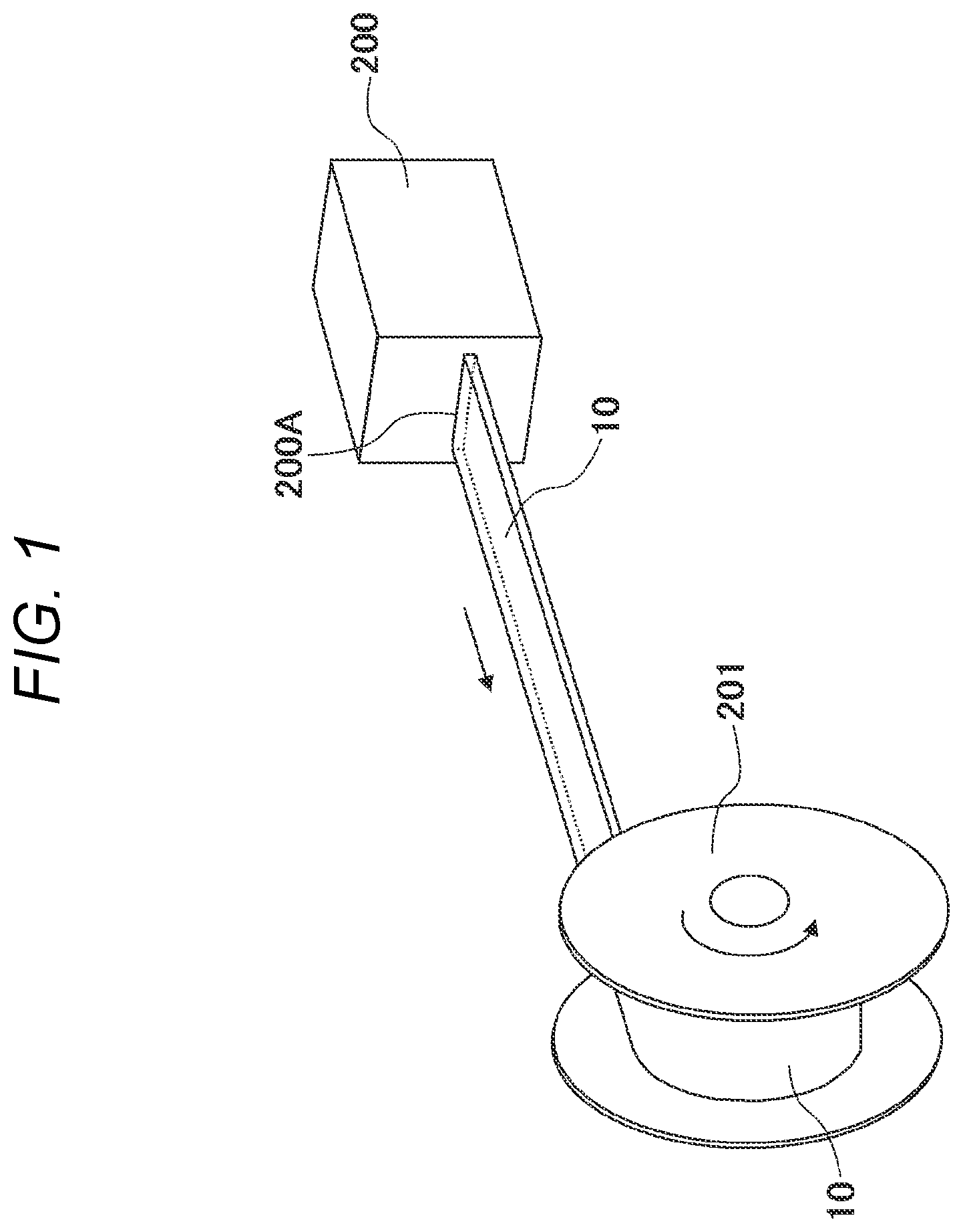
schematically shows the extrusion molding process. Such a process corresponds to a process of manufacturing a tube 100 A shown in A in a manufacturing method in related art. Here, a heated and melted resin material is pressurized by an extrusion molding machine 200 , and is extruded from an opening portion 200 A to be cooled, so that a tube material 10 which serves as an original form of the spiral tube is manufactured. Since a cross-sectional shape, which is perpendicular to a longitudinal direction of the tube material 10 is the same as a shape of the opening portion 200 A and is formed continuously, the tube material 10 can be wound and accommodated around a reel 201 in a long state.
Here, a cross-sectional shape along an injection direction (longitudinal direction) of the tube material 10 is the same as the shape of the opening portion 200 A. Here, as a simplest example, such a shape is assumed to be a simple rectangular shape as shown in . Therefore, the tube material 10 has a tape shape.
A and 2 B schematically show the mounting process. As shown in A , the tube material 10 is unwound and drawn from the reel 201 , where the tube material 10 is wound, by a member feeding roller 202 as indicated by arrow A. The drawn tube material 10 is heated to a temperature equal to or higher than a softening temperature thereof by a shape changing portion 210 and is then taken out as indicated by arrow B.
Thereafter, the tube material 10 drawn from the shape changing portion 210 is wound around a harness bundle HA as shown in B . At this time, the shape changing portion 210 is formed in an arc shape as shown in the drawing. Therefore, the tube material 10 drawn from the shape changing portion 210 has a curved shape so as to be wound around the harness bundle HA. When the harness bundle HA is moved as indicated by arrow C, the tube material 10 is cooled after being wound, and is thereby cured to form a spiral tube 20 . At this time, a flat plate-shaped protective cover 220 extending in a vertical direction is provided between the harness bundle HA and the shape changing portion 210 . A cutting blade 230 moves up and down along a surface of the protective cover 220 on the side of the harness bundle HA. A length of the spiral tube 20 can be set by cutting the tube material 10 when the cutting blade 230 moves from an upper side to a lower side. The harness bundle HA may also be moved as indicated by arrow C and rotated in such a manner that the tube material 10 is wound around the harness bundle HA in a shown direction.
In this manufacturing method, as shown in B , the spiral tube 20 is cut to a predetermined length after being mounted on the harness bundle HA. Therefore, it is not necessary to mount the spiral tube on the harness bundle HA by an operator or another device. Moreover, since the tube material 10 is wound around the harness bundle HA in the state of being heated and softened by the shape changing portion 210 , the spiral tube 20 can be reliably and easily mounted.
Since the tube material 10 is stored in the state of being wound around the reel 201 after the extrusion molding process and is cut to a desired length in the mounting process ( B ) so as to be used, it is not necessary to manage the spiral tube after cutting for each length as shown in B .
A shows the shape of the opening portion 200 A of the extrusion molding machine 200 shown in . Here, the opening portion 200 A has a rectangular shape that is thin in the vertical direction. Therefore, the tube material 10 obtained in this manner has the tape shape, and is easy to be wound around the reel 201 . It is also easy to wind the tube material 10 spirally around the harness bundle HA after passing through the shape changing portion 210 , as shown in B . B schematically shows a cross section along a central axis of the harness bundle HA in this case. The shape of each tube material 10 shown in B corresponds to the shape of the opening portion 200 A shown in A . Here, an interval between adjacent tube materials 10 of the spiral tube 20 after the mounting is H (H>0). H corresponds to a width of the cutout portion S shown in B .
A form of the spiral tube 20 is the same as that of the spiral tube 100 in the related art in a state where the spiral tube 20 is mounted on the harness bundle HA as shown in B . However, according to the above-described manufacturing method, various forms, which are difficult to be achieved by the manufacturing method in the related art as shown in A to 10 C , can be easily achieved for the spiral tube. Hereinafter, such modifications will be described.
According to the manufacturing method in the related art shown in A to 10 C , the shape of the spiral tube 100 does not change before mounting ( B ) and after mounting. In contrast, according to the manufacturing method of the present invention, the shape of the spiral tube after mounting can be set by the extrusion molding process or the mounting process.
First Modification
In a first modification, a shape of the tube material 10 (extrusion molding process) is the same as that in the case of A , and the shape of the spiral tube after mounting is different from that of the spiral tube 20 of B by changing conditions of the mounting process. A shape of a spiral tube 21 is shown in in correspondence with B .
The spiral tube 21 is set in such a manner that the tube materials 10 adjacent to each other on a surface of the harness bundle HA partially overlap with each other, and corresponds to a case where H<0 in B . Such a spiral tube 21 can be obtained by setting a moving speed along arrow C in the mounting process ( B ) to be smaller than that in the case of B .
When the spiral tube 21 shown in B is used, the surface of the harness bundle HA is exposed in a region of the interval H between the adjacent tube materials 10 , whereas the surface of the harness bundle HA is not exposed within a range where the spiral tube 21 is mounted in a case where the spiral tube 21 shown in is used. Therefore, the harness bundle HA can be more reliably protected as compared with the spiral tube 20 described above. In the manufacturing method shown in A to 10 C , since the shape of the spiral tube 100 before mounting and the shape of the spiral tube 100 after mounting are the same, it is obvious that it is extremely difficult to manufacture the spiral tube 21 which has such a shape.
Second Modification
In a second modification, the shape of the tube material 10 (extrusion molding process) is the same as that in the case of A , while contents of the mounting process are different from that in the case of B . A shape of a spiral tube 22 is shown in in correspondence with B . Here, the spiral tube 22 has a two-layer structure including a lower layer spiral tube 22 A and an upper layer spiral tube 22 B. The lower layer spiral tube 22 A and the upper layer spiral tube 22 B use the same tube material 10 , have the same form as the spiral tube 20 of B , and are manufactured in the same manner. Here, the tube material 10 constituting the upper layer spiral tube 22 B is wound so as to be positioned above a gap between the tube materials 10 constituting the lower layer spiral tube 22 A.
In this case, first, the lower layer spiral tube 22 A is manufactured by the same mounting process (first mounting process) as in the case of manufacturing the spiral tube 20 . Thereafter, a mounting process (second mounting process) for manufacturing the upper layer spiral tube 22 B is performed after a position of the harness bundle HA where the lower layer spiral tube 22 A is mounted is adjusted to achieve a structure of .
When the spiral tube 22 is used, the surface of the harness bundle HA is still prevented from being exposed within a range where the spiral tube 22 is mounted, and thus the harness bundle HA can be more reliably protected in the same manner as the spiral tube 21 . Moreover, similarly to the spiral tube 21 , it is difficult to manufacture the spiral tube 22 by the manufacturing method in the related art, whereas the spiral tube 22 can be easily manufactured according to the above-described manufacturing method.
Third Modification
In a third modification, since a tube material having a shape different from that of the tube material 10 , which has the simple flat plate shape, is used, the shape of the opening portion of the extrusion molding machine in the extrusion molding process is different. A shows an opening portion 203 A of an extrusion molding machine 203 used here. B shows in detail a cross-sectional shape of a tube material 11 obtained thereby, and such a shape is the same as a shape of the opening portion 203 A. In B , a first engaging portion (engaging portion) 11 A which locally protrudes downward is formed on a left end portion, while a second engaging portion (engaging portion) 11 B which locally protrudes upward is formed on a right end portion. A curved surface portion (deformation portion) 11 C having a curved surface shape whose upper side has a convex shape is formed between the first engaging portion 11 A and the second engaging portion 11 B. Since the curved surface portion 11 C has such a curved surface shape, the curved surface portion 11 C can expand and contract in a left-right direction in the drawing. A flat first engaging portion support surface 11 D is formed on an upper side between the second engaging portion 11 B located on a right side and the curved surface portion 11 C. Since the curved surface portion 11 C has the convex shape on the upper side, a first engaging portion locking surface 11 E, which is substantially perpendicular to the first engaging portion support surface 11 D, is formed on a left side of the first engaging portion support surface 11 D.
A spiral tube 23 shown in is manufactured through using the tube material 11 by performing the mounting process in such a manner that the adjacent tube materials 11 partially overlap each other on the surface of the harness bundle HA, as in the case of manufacturing the spiral tube 21 shown in . Since the adjacent tube materials 11 of the spiral tube 23 partially overlap with each other, among the two tube materials 11 adjacent to each other in the left-right direction in , the first engaging portion 11 A of the right tube material 11 is located on a left side of the second engaging portion 11 B of the left tube material 11 .
A to 8 C show a state of a shape change according to forces acting on the two adjacent tube materials 11 in a horizontal direction when the two adjacent tube materials 11 partially overlap each other in this way. Here, A shows a situation where no force is applied, B shows a situation where forces are applied in directions separating the two tube materials 11 from each other, and C shows a situation where forces are applied in directions bringing the two tube materials 11 close to each other. In A , the first engaging portion 11 A of the right tube material 11 is located between the second engaging portion 11 B and the first engaging portion locking surface LIE of the left tube material 11 .
In the state of B where the forces in the directions of separating the two tube materials 11 are applied in such a state, since the first engaging portion 11 A of the right tube material 11 is engaged with the second engaging portion 11 B of the left tube material 11 from the left side, the forces of extending each of the two tube materials 11 in the left-right direction act on the two tube materials 11 . As a result, each of the easily deformable curved surface portions 11 C is deformed so as to be stretched in the left-right direction from the state of A .
On the other hand, in the state of C where the forces in the directions of bringing the two tube materials 11 close to each other are applied, the first engaging portion 11 A of the right tube material 11 is locked from the right side by the first engaging portion locking surface 11 E of the left tube material 11 . As a result, the forces that compress each of the two tube materials 11 in the left-right direction act on the two tube materials 11 , and each of the curved surface portions 11 C which are easily deformed is compressed in the left-right direction from the state of A and deformed.
Therefore, in any state of A to 8 C , the tube material 11 moves and deforms in the horizontal direction according to the situations, and a form where the adjacent tube materials 11 partially overlap each other in the horizontal direction and are engaged with each other is maintained.
shows, in correspondence with , a second state where the harness bundle HA is bent in a first state where the spiral tube 23 is mounted on the harness bundle HA as shown in . In , on the upper side of the harness bundle HA, the forces in the directions of separating the two adjacent tube materials 11 are applied, so that the state of B is obtained. The forces in the directions of bringing the two adjacent tube materials 11 close to each other are applied on the lower side of the harness bundle HA, so that the state of C is obtained. Therefore, the adjacent tube materials 11 partially overlap with each other in the horizontal direction on both of the sides, the form where the tube materials 11 are engaged with each other is maintained, the form of the spiral tube 23 is stably maintained, and thus the harness bundle HA is stably protected. Moreover, since each tube material 11 can be easily brought into the state shown in by moving and deforming each tube material 11 in the horizontal direction as described above, the harness bundle HA can be easily deformed into such a state.
The tube material 11 constituting the spiral tube 23 having such a shape can be easily manufactured through using the extrusion molding machine 203 (opening portion 203 A). By using the tube material 11 to perform the mounting process, the spiral tube 23 can be easily manufactured and can be easily mount on the harness bundle HA. On the other hand, according to the manufacturing method in the related art shown in A to 10 C , it is extremely difficult to manufacture the spiral tube 23 which has such a shape.
As for the cross-sectional shape, structures other than the above-described structures can be used as structures of the engaging portions engaging the tube materials which are adjacent to each other in the horizontal direction. At this time, the tube material including such an engaging portion can be easily manufactured to have a shape other than the above-described shape depending on the shape of the opening portion in the extrusion molding process.
The same also applies to the structure of the curved surface portion (deformation portion). Any shape can be used as long as the curved surface portion can be easily expanded and contracted in the horizontal direction and can be easily formed by extrusion molding. Alternatively, as long as the tube material itself is a material that is easily deformed, the curved surface portion (deformation portion) that is particularly easily deformed may not be provided in the structure. Although the spiral tube is mounted to the harness bundle HA that includes the plurality of wire harnesses in the above example, an object to be mounted may also be one single wire harness.
According to one or more embodiments, it is possible to provide a method for manufacturing a spiral tube that can be easily manufactured and mounted.
Figures (8)
Citations
This patent cites (12)
- US5802814
- US20190277447
- USH06-88129
- US2000-244145
- US2001-236839
- US2003-65471
- US2009-117171
- US2010-255671
- US2010255671
- US2016-63584
- US2016063584
- US6088129