Abstract
A wire harness including: a first wire; a ring-shaped first electromagnetic wave absorber having a first through hole through which the first wire passes; a first restricting member that restricts relative movement of the first electromagnetic wave absorber with respect to the first wire in a length direction of the first wire; a second wire; a ring-shaped second electromagnetic wave absorber having a second through hole through which the second wire passes; and a second restricting member that restricts relative movement of the second electromagnetic wave absorber with respect to the second wire in a length direction of the second wire, wherein the first electromagnetic wave absorber is provided so as to overlap with a portion of the second electromagnetic wave absorber in a plan view from a first central axis direction in which a central axis of the first through hole extends.
Claims (4)
1. A wire harness comprising: a first wire; a ring-shaped first electromagnetic wave absorber having a first through hole through which the first wire passes; a first restricting member that restricts relative movement of the first electromagnetic wave absorber with respect to the first wire in a length direction of the first wire; a second wire; a ring-shaped second electromagnetic wave absorber having a second through hole through which the second wire passes; and a second restricting member that restricts relative movement of the second electromagnetic wave absorber with respect to the second wire in a length direction of the second wire, wherein: the first electromagnetic wave absorber is provided so as to overlap with a portion of the second electromagnetic wave absorber in a plan view from a first central axis direction in which a central axis of the first through hole extends; an inner circumferential surface of the first through hole opposes an outer circumference of the first wire; when the first electromagnetic wave absorber is viewed along the central axis of the first through hole, the inner circumferential surface of the first through hole has a first portion and a second portion arranged at a position point-symmetrical to the first portion with respect to the central axis of the first through hole; the first restricting member fixes the first electromagnetic wave absorber to the first wire such that the first wire is in contact with the first portion and is separated from the second portion; and the first portion is a portion arranged at a position spaced apart from the second wire relative to the second portion in a direction intersecting the first central axis direction.
3. A wire harness comprising: a first wire; a ring-shaped first electromagnetic wave absorber having a first through hole through which the first wire passes; a first restricting member that restricts relative movement of the first electromagnetic wave absorber with respect to the first wire in a length direction of the first wire; a second wire; a ring-shaped second electromagnetic wave absorber having a second through hole through which the second wire passes; and a second restricting member that restricts relative movement of the second electromagnetic wave absorber with respect to the second wire in a length direction of the second wire, wherein: the first electromagnetic wave absorber is provided so as to overlap with a portion of the second electromagnetic wave absorber in a plan view from a first central axis direction in which a central axis of the first through hole extends; an inner circumferential surface of the first through hole opposes an outer circumference of the first wire; when the first electromagnetic wave absorber is viewed along the central axis of the first through hole, the inner circumferential surface of the first through hole has a first portion and a second portion arranged at a position point-symmetrical to the first portion with respect to the central axis of the first through hole; the second portion is a portion arranged at a position near the second wire relative to the first portion in a direction intersecting the first central axis direction; and the first restricting member fixes the first electromagnetic wave absorber to the first wire such that the first wire is in contact with the second portion and is separated from the first portion.
Show 2 dependent claims
2. The wire harness according to claim 1 , wherein: an inner circumferential surface of the second through hole opposes an outer circumference of the second wire, when the second electromagnetic wave absorber is viewed along a central axis of the second through hole, the inner circumferential surface of the second through hole has a third portion and a fourth portion arranged at a position point-symmetrical to the third portion with respect to the central axis of the second through hole, the third portion is a portion arranged at a position spaced apart from the first wire relative to the fourth portion in a direction intersecting a second central axis direction in which the central axis of the second through hole extends, and the second restricting member fixes the second electromagnetic wave absorber to the second wire such that the second wire is in contact with the third portion and is separated from the fourth portion.
4. The wire harness according to claim 3 , wherein: an inner circumferential surface of the second through hole opposes an outer circumference of the second wire, when the second electromagnetic wave absorber is viewed along the central axis of the second through hole, the inner circumferential surface of the second through hole has a third portion and a fourth portion arranged at a position point-symmetrical to the third portion with respect to the central axis of the second through hole, the fourth portion is a portion arranged at a position near the first wire relative to the third portion in a direction intersecting a second central axis direction in which the central axis of the second through hole extends, and the second restricting member fixes the second electromagnetic wave absorber to the second wire such that the second wire is in contact with the fourth portion and is separated from the third portion.
Full Description
Show full text →
BACKGROUND
This disclosure relates to a wire harness.
Conventionally, wire harnesses, which are provided with wires that electrically connect a plurality of electrical devices and electromagnetic wave absorbing members that absorb electromagnetic waves (electromagnetic noise) emitted from the wires, are known as wire harnesses that are mounted in vehicles such as hybrid vehicles and electric vehicles. As a result of inserting a plurality of wires into a through hole in an electromagnetic wave absorbing member constituted by a ferrite core, the electromagnetic wave absorbing member is provided on an outer circumference of the wires in a wire harness of this type (see JP 2014-130886A, for example).
SUMMARY
Incidentally, with the above-described wire harness, the larger the electromagnetic waves to be reduced are, the larger the size of the electromagnetic wave absorbing member is. When a plurality of wires are inserted into such a large electromagnetic wave absorbing member, there is a risk that the electromagnetic wave absorbing member may vibrate due to vibration accompanying traveling of the vehicle or the like, for example, and the wires may be shaken by the vibration of the electromagnetic wave absorbing member, and the wires may be damaged.
An exemplary aspect of the disclosure provides a wire harness capable of reducing damage to a wire.
The wire harness of the present disclosure includes: a first wire; a ring-shaped first electromagnetic wave absorber having a first through hole through which the first wire passes; a first restricting member that restricts relative movement of the first electromagnetic wave absorber with respect to the first wire in a length direction of the first wire; a second wire; a ring-shaped second electromagnetic wave absorber having a second through hole through which the second wire passes; and a second restricting member that restricts relative movement of the second electromagnetic wave absorber with respect to the second wire in a length direction of the second wire, wherein the first electromagnetic wave absorber is provided so as to overlap with a portion of the second electromagnetic wave absorber in a plan view from a first central axis direction in which a central axis of the first through hole extends.
According to the wire harness of the present disclosure, an effect of being able to reduce damage to a wire is exhibited.
BRIEF DESCRIPTION OF THE DRAWINGS
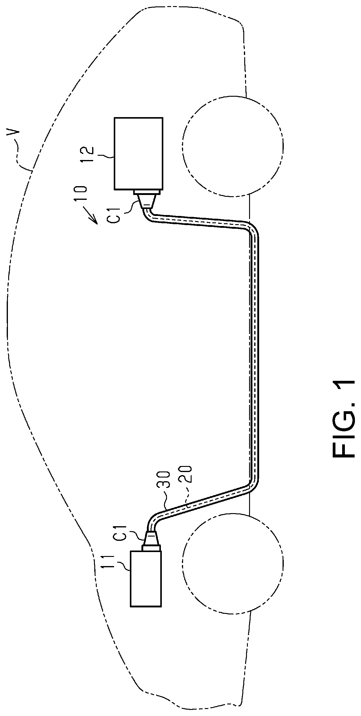
is a schematic configuration diagram showing a wire harness according to an embodiment.
is a schematic cross-sectional view showing a wire harness according to an embodiment.
is a schematic cross-sectional view (a cross-sectional view taken along line 3 - 3 in ) showing a wire harness according to an embodiment.
is a schematic transverse cross-sectional view showing a wire harness according to a modified example.
is a schematic cross-sectional view showing a wire harness according to a modified example.
is a schematic transverse cross-sectional view showing a wire harness according to a modified example.
is a schematic transverse cross-sectional view showing a wire harness according to a modified example.
is a schematic transverse cross-sectional view showing a wire harness according to a modified example.
is a schematic transverse cross-sectional view showing a wire harness according to a modified example.
is a schematic cross-sectional view showing a wire harness according to a modified example.
is a schematic perspective view showing a wire harness according to a modified example.
is a schematic transverse cross-sectional view (a cross-sectional view taken along line 12 - 12 in ) showing a wire harness according to a modified example.
is a schematic cross-sectional view showing a wire harness according to a modified example.
is a schematic configurational diagram showing a wire harness according to a modified example.
DETAILED DESCRIPTION OF EMBODIMENTS
First, embodiments of the present disclosure will be listed and described.
•
• [1] The wire harness of the present disclosure includes: a first wire member including a first wire; a ring-shaped first electromagnetic wave absorbing member having a first through hole through which the first wire member passes; a first restricting member that restricts relative movement of the first electromagnetic wave absorbing member with respect to the first wire member in a length direction of the first wire member; a second wire member including a second wire; a ring-shaped second electromagnetic wave absorbing member having a second through hole through which the second wire member passes; and a second restricting member that restricts relative movement of the second electromagnetic wave absorbing member with respect to the second wire member in a length direction of the second wire member, in which the first electromagnetic wave absorbing member is provided so as to overlap with a portion of the second electromagnetic wave absorbing member in a plan view from a first central axis direction in which a central axis of the first through hole extends.
According to this configuration, the first electromagnetic wave absorbing member is provided on the first wire member, and the second electromagnetic wave absorbing member is provided on the second wire member. That is, the first electromagnetic wave absorbing member and the second electromagnetic wave absorbing member are individually provided for the first wire member and the second wire member, respectively. As a result, the electromagnetic waves to be reduced in each of the first electromagnetic wave absorbing member and the second electromagnetic wave absorbing member can be made smaller compared to the case where one electromagnetic wave absorbing member is provided for a plurality of wire members. For this reason, compared to the case where one electromagnetic wave absorbing member is provided for a plurality of wire members, each of the first electromagnetic wave absorbing member and the second electromagnetic wave absorbing member can be made more compact, and mass of each of the first electromagnetic wave absorbing member and the second electromagnetic wave absorbing member can be reduced. As a result, if the first electromagnetic wave absorbing member and the second electromagnetic wave absorbing member vibrate accompanying the traveling of the vehicle or the like, the loads respectively input to the first wire member and the second wire member from the first electromagnetic wave absorbing member and the second electromagnetic wave absorbing member can be reduced. As a result, it is possible to suppress damage to the first wire member and the second wire member caused by the vibration of the first electromagnetic wave absorbing member and the second electromagnetic wave absorbing member. Consequently, it is possible to suppress damage to the first wire and the second wire.
Also, since the first electromagnetic wave absorbing member is provided so as to overlap with a portion of the second electromagnetic wave absorbing member in a plan view from the first central axis direction, it is possible to suppress an increase in the size of the wire harness.
Here, a “ring” in the present specification includes a circular ring having a circular outer edge shape, a ring having an elliptical or ovoid outer edge shape, a polygonal ring having a polygonal outer edge shape, and a ring having a polygonal outer edge shape with rounded corners, and refers to a ring whose outer shape is composed of any closed shape connected by straight lines or curved lines. A “ring” includes a ring that is a shape having a through hole in a plan view, a shape in which the outer edge shape and the inner circumference shape of the through hole are the same shape, and a shape in which the outer edge shape and the inner circumference shape of the through hole are different from each other. A “ring” includes a ring having a predetermined length extending along the central axis direction in which the central axis passing through the center of the through hole extends, and the length thereof may be large or small. Also, a “ring” in the present specification may be regarded as a ring overall, and includes an object having a notch in a portion thereof, as with a C-shaped object.
•
• [2] It is preferable that an inner circumferential surface of the first through hole opposes an outer circumferential surface of the first wire member, when the first electromagnetic wave absorbing member is viewed along the central axis of the first through hole, the inner circumferential surface of the first through hole has a first portion and a second portion arranged at a position point-symmetrical to the first portion with respect to the central axis of the first through hole, and the first restricting member fixes the first electromagnetic wave absorbing member to the first wire member such that the first wire member is in contact with the first portion and is separated from the second portion.
According to this configuration, inside the first through hole of the first electromagnetic wave absorbing member, the first electromagnetic wave absorbing member and the first wire member are fixed to each other (integrated with each other) in a state in which the first wire member is in contact with the first portion and is arranged offset to the first portion side. For this reason, even if the first electromagnetic wave absorbing member vibrates accompanying traveling of the vehicle or the like, it is possible to suppress shaking of the first wire member in the first through hole caused by vibration of the first electromagnetic wave absorbing member. For example, compared to the case where the first electromagnetic wave absorbing portion and the first wire member are fixed in a state in which the first wire member is not in contact with the inner circumferential surface of the first through hole, it is possible to suppress movement of the first wire member in the first through hole caused by vibration of the first electromagnetic wave absorbing member. As a result, it is possible to suppress wearing of the first wire member caused by contact with the inner circumferential surface of the first through hole, and it is possible to suitably suppress damage to the first wire member caused by vibration of the first electromagnetic wave absorbing member.
Here, “opposing” as used in the present specification means that surfaces or members are in front of each other, and encompasses not only the case where they are completely in front of each other, but also the case where they are partially in front of each other. Also, the term “opposing” in the present specification encompasses both the case where a member different from two portions is interposed between the two portions and the case where nothing is interposed between the two portions.
•
• [3] It is preferable that the first portion is a portion arranged at a position spaced apart from the second wire member relative to the second portion in a direction intersecting the first central axis direction.
According to this configuration, inside the first through hole, the first wire member is arranged offset to the side away from the second wire member. As a result, the first electromagnetic wave absorbing member and the second electromagnetic wave absorbing member can be largely overlapped with each other in a plan view from the first central axis direction. As a result, it is possible to suitably suppress an increase in the size of the wire harness.
•
• [4] It is preferable that an inner circumferential surface of the second through hole opposes an outer circumferential surface of the second wire member, when the second electromagnetic wave absorbing member is viewed along a central axis of the second through hole, the inner circumferential surface of the second through hole has a third portion and a fourth portion arranged at a position point-symmetrical to the third portion with respect to the central axis of the second through hole, the third portion is a portion arranged at a position spaced apart from the first wire member relative to the fourth portion in a direction intersecting a second central axis direction in which the central axis of the second through hole extends, and the second restricting member fixes the second electromagnetic wave absorbing member to the second wire member such that the second wire member is in contact with the third portion and is separated from the fourth portion.
According to this configuration, inside the second through hole of the second electromagnetic wave absorbing member, the second electromagnetic wave absorbing member and the second wire member are fixed to each other (integrated with each other) in a state where the second wire member is in contact with the third portion and is arranged offset to the third portion side. For this reason, even if the second electromagnetic wave absorbing member vibrates accompanying traveling of the vehicle or the like, it is possible to suppress shaking of the second wire member in the second through hole caused by vibration of the second electromagnetic wave absorbing member. For example, compared to the case where the second electromagnetic wave absorbing portion and the second wire member are fixed in a state where the second wire member is not in contact with the inner circumferential surface of the second through hole, it is possible to suppress movement of the second wire member in the second through hole caused by vibration of the second electromagnetic wave absorbing member. As a result, it is possible to suppress wearing of the second wire member caused by contact with the inner circumferential surface of the second through hole, and it is possible to suitably suppress damage to the second wire member caused by vibration of the second electromagnetic wave absorbing member.
Also, inside the second through hole, the second wire member is arranged offset to the side away from the first wire member. As a result, the first electromagnetic wave absorbing member and the second electromagnetic wave absorbing member can be largely overlapped with each other in a plan view from the first central axis direction. As a result, it is possible to suppress an increase in the size of the wire harness.
•
• [5] The inner circumferential surface of the first through hole opposes the outer circumferential surface of the first wire member, when the first electromagnetic wave absorbing member is viewed along the central axis of the first through hole, the inner circumferential surface of the first through hole has a first portion and a second portion arranged at a position point-symmetrical to the first portion with respect to the central axis of the first through hole, the second portion is a portion arranged at a position near the second wire member relative to the first portion in a direction intersecting the first central axis direction, and the first restricting member fixes the first electromagnetic wave absorbing member to the first wire member such that the first wire member is in contact with the second portion and is separated from the first portion.
According to this configuration, inside the first through hole of the first electromagnetic wave absorbing member, the first electromagnetic wave absorbing member and the first wire member are fixed to each other (integrated with each other) in a state where the first wire member is in contact with the second portion and is arranged offset to the second portion side. For this reason, even if the first electromagnetic wave absorbing member vibrates accompanying traveling of the vehicle or the like, it is possible to suppress shaking of the first wire member in the first through hole caused by vibration of the first electromagnetic wave absorbing member. For example, compared to the case where the first electromagnetic wave absorbing portion and the first wire member are fixed in a state in which the first wire member is not in contact with the inner circumferential surface of the first through hole, it is possible to suppress movement of the first wire member in the first through hole caused by vibration of the first electromagnetic wave absorbing member. As a result, it is possible to suppress wearing of the first wire member caused by contact with the inner circumferential surface of the first through hole, and it is possible to suitably suppress damage to the first wire member caused by vibration of the first electromagnetic wave absorbing member.
Also, inside the first through hole, the first wire member is arranged offset to the side near the second wire member. As a result, the first wire member and the second wire member can be provided in close proximity to each other. For this reason, for example, it is possible to reduce the size of the wire harness at the portion where the first electromagnetic wave absorbing member and the second electromagnetic wave absorbing member are not provided.
•
• [6] It is preferable that the inner circumferential surface of the second through hole opposes the outer circumferential surface of the second wire member, when the second electromagnetic wave absorbing member is viewed along the central axis of the second through hole, the inner circumferential surface of the second through hole has a third portion and a fourth portion arranged at a position point-symmetrical to the third portion with respect to the central axis of the second through hole, the fourth portion is a portion arranged at a position near the first wire member relative to the third portion in a direction intersecting a second central axis direction in which the central axis of the second through hole extends, and the second restricting member fixes the second electromagnetic wave absorbing member to the second wire member such that the second wire member is in contact with the fourth portion and is separated from the third portion.
According to this configuration, inside the second through hole of the second electromagnetic wave absorbing member, the second electromagnetic wave absorbing member and the second wire member are fixed to each other (integrated with each other) in a state where the second wire member is in contact with the fourth portion and is arranged offset to the fourth portion side. For this reason, even if the second electromagnetic wave absorbing member vibrates accompanying traveling of the vehicle or the like, it is possible to suppress shaking of the second wire member in the second through hole caused by vibration of the second electromagnetic wave absorbing member. For example, compared to the case where the second electromagnetic wave absorbing portion and the second wire member are fixed in a state where the second wire member is not in contact with the inner circumferential surface of the second through hole, it is possible to suppress movement of the second wire member in the second through hole caused by vibration of the second electromagnetic wave absorbing member. As a result, it is possible to suppress wearing of the second wire member caused by contact with the inner circumferential surface of the second through hole, and it is possible to suitably suppress damage to the second wire member caused by vibration of the second electromagnetic wave absorbing member.
Also, inside the second through hole, the second wire is arranged on the side closer to the first wire. As a result, the first wire and the second wire can be provided in close proximity to each other. For this reason, for example, it is possible to further reduce the size of the wire harness at the portion where the first electromagnetic wave absorbing member and the second electromagnetic wave absorbing member are not provided.
•
• [7] It is preferable to further include an electromagnetic shielding member that collectively surrounds the first wire member, the first electromagnetic wave absorbing member, the second wire member, and the second electromagnetic wave absorbing member.
According to this configuration, the electromagnetic waves emitted from the first wire can be reduced by the first electromagnetic wave absorbing member and the electromagnetic shielding member covering the outer circumference of the first electromagnetic wave absorbing member. Also, the electromagnetic waves emitted from the second wire can be reduced by the second electromagnetic wave absorbing member and the electromagnetic shielding member covering the outer circumference of the second electromagnetic wave absorbing member.
Furthermore, since the electromagnetic shielding member is provided so as to collectively surround the first electromagnetic wave absorbing member and the second electromagnetic wave absorbing member, the number of components can be reduced compared to the case where the electromagnetic shielding member is individually provided for the first electromagnetic wave absorbing member and the second electromagnetic wave absorbing member.
•
• [8] It is preferable to further include a cushioning member that covers a side surface of the first electromagnetic wave absorbing member facing toward the second electromagnetic wave absorbing member.
According to this configuration, a cushioning member can be interposed between the first electromagnetic wave absorbing member and the second electromagnetic wave absorbing member. As a result, it is possible to suppress direct contact between the first electromagnetic wave absorbing member and the second electromagnetic wave absorbing member and it is possible to suppress damage to the first electromagnetic wave absorbing member and the second electromagnetic wave absorbing member caused by contact between the first electromagnetic wave absorbing member and the second electromagnetic wave absorbing member.
•
• [9] It is preferable to further include: a first outer cover member that collectively accommodates the first wire member and the second wire member; and a protective member that covers an outer circumference of the first wire member, the second wire member, the first electromagnetic wave absorbing member, and the second electromagnetic wave absorbing member, which are exposed from the first outer cover member.
According to this configuration, the outer circumference of the first electromagnetic wave absorbing member and the second electromagnetic wave absorbing member is covered by the protective member. For this reason, a protective member can be interposed between the first electromagnetic wave absorbing member and second electromagnetic wave absorbing member and their peripheral components. As a result, it is possible to suppress direct contact between the first electromagnetic wave absorbing member and second electromagnetic wave absorbing member and the peripheral components, and therefore it is possible to suppress damage to the first electromagnetic wave absorbing member and the second electromagnetic wave absorbing member caused by contact with the peripheral components.
•
• [10] It is preferable that the first wire member includes the first wire and a first covering member that covers an outer circumference of the first wire, the second wire member includes the second wire and a second covering member that covers an outer circumference of the second wire, the first covering member passes through the first through hole while covering the outer circumference of the first wire, and the second covering member passes through the second through hole while covering the outer circumference of the second wire.
According to this configuration, the first wire is inserted through the first through hole of the first electromagnetic wave absorbing member while covered by the first covering member, and the second wire is inserted through the second through hole of the second electromagnetic wave absorbing member while covered by the second covering member. For this reason, it is possible to suppress a case in which the inner circumferential surface of the first through hole comes into direct contact with the outer circumferential surface of the first wire, and it is possible to suppress a case in which the inner circumferential surface of the second through hole comes into direct contact with the outer circumferential surface of the second wire. As a result, it is possible to suitably suppress damage to the first wire and the second wire caused by contact with the inner circumferential surfaces of the first through hole and the second through hole.
Detailed Description of Embodiments of the Disclosure
A specific example of a wire harness according to this disclosure will be described with reference to the drawings below. In the drawings, some of the components may be exaggerated or simplified for the sake of description. Also, the dimensional proportions of some parts may differ from their actual proportions. “Parallel” and “orthogonal” in this specification include not only strictly parallel and orthogonal but also generally parallel and orthogonal in a range in which the effects of this embodiment are achieved. Note that the present disclosure is not limited to these examples, but is indicated by the claims, and all changes that fall within the meaning and range of equivalency of the claims are intended to be embraced therein.
Overall Configuration of Wire Harness 10
A wire harness 10 shown in electrically connects two or three or more electric devices (devices). The wire harness 10 electrically connects, for example, an inverter 11 installed at the front of a vehicle V such as a hybrid vehicle or an electric vehicle, and a high-voltage battery 12 installed on the rear side of the vehicle V relative to the inverter 11 . The wire harness 10 is routed, for example, so as to pass under a floor of the vehicle V or the like. For example, an intermediate portion of the wire harness 10 in the length direction is routed so as to pass outside the vehicle interior, such as under the floor of the vehicle V. The inverter 11 is connected to a wheel drive motor (not shown) that is a power source for vehicle travel. The inverter 11 generates AC power from the DC power of the high-voltage battery 12 , and supplies the AC power to the motor. The high-voltage battery 12 is, for example, a battery capable of supplying a voltage of several hundred volts.
The wire harness 10 has one or a plurality of (in the present embodiment, two) wires 20 , a pair of connectors C 1 that are attached to both end portions of the wires 20 , and an outer cover member 30 that collectively surrounds the plurality of wires 20 .
Configuration of Wires 20
One end portion of each wire 20 is connected to the inverter 11 via the connector C 1 , and the other end of each wire 20 is connected to the high-voltage battery 12 via the connector C 1 . Each wire 20 is formed in a long shape so as to extend in the front-rear direction of the vehicle V, for example. Each wire 20 is formed so as to be bent in a two-dimensional shape or a three-dimensional shape, for example, depending on the routing path of the wire harness 10 . Each wire 20 is a high-voltage wire that can handle, for example, a high voltage and a large current. Each wire 20 may be, for example, a shielded wire having an electromagnetic shielding structure, or a non-shielded wire having no electromagnetic shielding structure. Each wire 20 of this embodiment is a non-shielded wire.
As shown in , the wire 20 has a positive-side wire 20 A connected to, for example, a positive terminal of the high-voltage battery 12 (see ) and a negative-side wire 20 B connected to the negative terminal of the high-voltage battery 12 (see ).
The wires 20 A and 20 B are covered wires having a core wire 21 made of a conductor and an insulating covering 22 covering the outer circumference of the core wire 21 . As the core wire 21 , for example, a stranded wire made by twisting together a plurality of metal strands, a columnar conductor made of one columnar metal rod having a solid structure inside, a tubular conductor having a hollow structure inside, or the like can be used. As the core wire 21 , for example, a stranded wire, a columnar conductor, and a tubular conductor may be used in combination. Examples of the columnar conductor include a single core wire and a bus bar. The core wire 21 of the present embodiment is a stranded wire. As the material of the core wire 21 , for example, a metal material that is copper-based, aluminum-based, or the like can be used.
Configuration of Core Wire 21
The cross-sectional shape (i.e., a transverse cross-sectional shape) obtained by cutting the core wire 21 along a plane orthogonal to the length direction of the core wire 21 may be any shape. The transverse cross-sectional shape of each core wire 21 is a circular, semicircular, polygonal, square, or flat shape, for example. The transverse cross-sectional shape of the core wire 21 in this embodiment is a circular shape.
Configuration of Insulating Covering 22
The insulating coverings 22 respectively cover the outer circumferential surfaces of the core wires 21 over the entire circumference in the circumferential direction, for example. The insulating covering 22 is made of an insulating material such as a synthetic resin, for example. It is possible to use a synthetic resin containing polyolefin-based resin as a main component, such as crosslinked polyethylene or crosslinked polypropylene, as the material of the insulating covering 22 , for example. Materials of one or more types can be used alone or in combination of two or more as the material of the insulating covering 22 . The insulating covering 22 can be formed through, for example, extrusion molding (extrusion coating) performed on the core wire 21 .
Configuration of Outer Cover Member 30
The outer cover member 30 shown in has a long cylindrical shape overall. A plurality of wires 20 are accommodated in the internal space of the outer cover member 30 . The outer cover member 30 is formed, for example, so as to surround the outer circumference of the plurality of wires 20 over the entire circumference in the circumferential direction. The outer cover member 30 protects the wires 20 from, for example, flying objects and water droplets. As the outer cover member 30 , for example, a metal or resin pipe, a resin protector, a flexible corrugated tube made of resin, a rubber waterproof cover, or a combination thereof can be used. As the material of the metal pipe, a metal material such as a copper-based metal material or an aluminum-based metal material can be used. As the material of the resin protector and the corrugated tube, for example, a resin material having conductivity or a resin material having no conductivity can be used. As the resin material, for example, synthetic resins such as polyolefin, polyamide, polyester, and ABS resin can be used.
As shown in , the outer cover member 30 has, for example, a corrugated tube 40 , a corrugated tube 50 , and a protective member 60 . As the material of the corrugated tubes 40 and 50 of the present embodiment, a resin material having no conductivity is used. As the resin material, for example, synthetic resins such as polyolefin, polyamide, polyester, and ABS resin can be used.
Configuration of Corrugated Tube 40
The corrugated tube 40 has, for example, a tubular shape that collectively surrounds the outer circumference of a plurality of wires 20 A and 20 B overall. The corrugated tube 40 is provided, for example, so as to surround the outer circumferences of the plurality of wires 20 A and 20 B over the entire circumference in the circumferential direction. The corrugated tube 40 is provided, for example, so as to surround a portion in the length direction (axial direction) of the wires 20 A and 20 B. The corrugated tube 40 has an accordion structure in which ring-shaped protrusions 41 and ring-shaped recesses 42 are arranged alternatingly along the length direction thereof. The corrugated tube 40 is more flexible than the core wire 21 . The corrugated tube 40 of the present embodiment is formed in a cylindrical shape.
Configuration of Corrugated Tube 50
The corrugated tube 50 is provided, for example, spaced apart from the corrugated tube 40 in the length direction of the wires 20 A and 20 B. The corrugated tube 50 has, for example, a tubular shape that collectively surrounds the outer circumferences of the plurality of wires 20 A and 20 B overall. The corrugated tube 50 is provided, for example, so as to surround the outer circumference of the plurality of wires 20 A and 20 B over the entire circumference in the circumferential direction. The corrugated tube 50 is provided, for example, so as to surround a portion in the length direction of the wires 20 A and 20 B. The corrugated tube 50 has an accordion structure in which ring-shaped protrusions 51 and ring-shaped recesses 52 are arranged alternatingly along the length direction thereof. The corrugated tube 50 is more flexible than the core wire 21 . The corrugated tube 50 of the present embodiment is formed in a cylindrical shape.
Configuration of Protective Member 60
The protective member 60 is provided so as to bridge between the outer circumference of the corrugated tube 40 and the outer circumference of the corrugated tube 50 , for example. The protective member 60 has, for example, a tubular shape in which both ends in the length direction of the wires 20 A and 20 B are open. As the material of the protective member 60 , for example, an elastic material having a relatively high hardness can be used. As the elastic material, for example, rubber such as ethylene propylene diene rubber or elastomer can be used.
Configuration of Wire Harness 10
The wire harness 10 has, for example, an electromagnetic wave absorbing member 70 A (electromagnetic wave absorber) provided on a portion in the length direction of the wire 20 A and an electromagnetic wave absorbing member 70 B (electromagnetic wave absorber) provided on a portion in the length direction of the wire 20 B. The wire harness 10 has, for example, a restricting member 80 A that restricts relative movement of the electromagnetic wave absorbing member 70 A with respect to the wire 20 A in the length direction of the wire 20 A, and a restricting member 80 B that restricts relative movement of the electromagnetic wave absorbing member 70 B with respect to the wire 20 B in the length direction of the wire 20 B. The electromagnetic wave absorbing member 70 A is provided for, for example, one wire 20 A. The electromagnetic wave absorbing member 70 B is provided for, for example, one wire 20 B. In other words, the electromagnetic wave absorbing members 70 A and 70 B are individually provided for each of the wires 20 A and 20 B. The electromagnetic wave absorbing member 70 A and the electromagnetic wave absorbing member 70 B are provided, for example, at positions spaced apart from each other in the length direction of the wires 20 A and 20 B.
Here, the electromagnetic wave absorbing member 70 A and the electromagnetic wave absorbing member 70 B have the same structure, and the restricting member 80 A and the restricting member 80 B have the same structure. For this reason, the electromagnetic wave absorbing member 70 B is denoted by the same reference numerals as the electromagnetic wave absorbing member 70 A, the restricting member 80 B is designated by the same reference numerals as the restricting member 80 A, and detailed description of each of these elements is omitted.
Configuration of Electromagnetic Wave Absorbing Member 70 A
The electromagnetic wave absorbing member 70 A is provided on the outer circumference of the wire 20 A located between the corrugated tube 40 and the corrugated tube 50 , for example. For example, in the length direction of the wire 20 A, the corrugated tube 40 is provided on one side of the electromagnetic wave absorbing member 70 A, and the electromagnetic wave absorbing member 70 B and the corrugated tube 50 are provided on the other side of the electromagnetic wave absorbing member 70 A. The electromagnetic wave absorbing member 70 A is provided, for example, spaced apart from the corrugated tube 40 in the length direction of the wire 20 A. The electromagnetic wave absorbing member 70 A is provided, for example, spaced apart from the electromagnetic wave absorbing member 70 B and the corrugated tube 50 in the length direction of the wire 20 A. The electromagnetic wave absorbing member 70 A is exposed from, for example, the corrugated tubes 40 and 50 . The electromagnetic wave absorbing member 70 A is provided so as to surround the outer circumference of one wire 20 A, for example. The electromagnetic wave absorbing member 70 A absorbs some of the electromagnetic waves (electromagnetic noise) emitted from the wire 20 A, for example.
The electromagnetic wave absorbing member 70 A has, for example, a through hole 71 X through which one wire 20 A passes. The electromagnetic wave absorbing member 70 A has a ring shape, for example, due to having the through hole 71 X. The electromagnetic wave absorbing member 70 A has, for example, the through hole 71 X in a plan view from the length direction of the wire 20 A, and is formed in a ring shape having a predetermined length extending along a first central axis direction in which the central axis passing through the center of the through hole 71 X extends. In the present embodiment, the first central axis direction of the electromagnetic wave absorbing member 70 A is set to a direction extending parallel to the length direction of the wire 20 A.
The through hole 71 X is formed, for example, so as to pass through the electromagnetic wave absorbing member 70 A in the length direction of the wire 20 A. The wire 20 A is provided so as to pass through the through hole 71 X, for example. The inner circumferential surface of the through hole 71 X opposes the outer circumferential surface of the wire 20 A.
The electromagnetic wave absorbing member 70 A of the present embodiment is composed of only a ring-shaped magnetic core 72 . The magnetic core 72 of the present embodiment is formed in a circular ring shape. The magnetic core 72 has a function of reducing electromagnetic waves emitted from the wire 20 A by being arranged so as to oppose the wire 20 A over the entire circumference in the circumferential direction of the wire 20 A, for example. The magnetic core 72 absorbs electromagnetic waves emitted from, for example, the wire 20 A, and converts the energy of the electromagnetic waves into mechanical energy such as vibration, or thermal energy. As a result, adverse effects that the electromagnetic waves emitted from the wire 20 A have on peripheral devices and the like are reduced.
The magnetic core 72 is, for example, a molded product containing a soft magnetic material. Examples of the soft magnetic material include iron (Fe), iron alloys and ferrites. Examples of the iron alloy include a Fe-silicon (Si) alloy and a Fe-nickel (Ni) alloy. As the magnetic core 72 , for example, a ferrite core, an amorphous core, or a permalloy core can be used. The ferrite core is made of, for example, soft ferrite exhibiting soft magnetism. Examples of the soft ferrite include a ferrite containing nickel (Ni) and zinc (Zn) and a ferrite containing manganese (Mn) and zinc (Zn). The material of the magnetic core 72 can be appropriately selected, for example, according to the frequency band of the electromagnetic noise to be reduced.
As shown in , the magnetic core 72 of the present embodiment is formed continuously over the entire circumference in the circumferential direction, and is formed in a closed ring shape. That is, the magnetic core 72 of the present embodiment is formed in a structure in which the entirety is connected to form a continuous ring, that is, an endless structure in which the start point and the end point coincide with each other. In other words, no slit extending along the first central axis direction is formed in the magnetic core 72 of the present embodiment. The magnetic core 72 of this embodiment is constituted by one component. Note that in the present embodiment, the magnetic core 72 was constituted by one component, but a plurality of core materials may be combined to form a ring-shaped magnetic core 72 . For example, the magnetic core 72 may be formed into a circular ring shape by combining a pair of core materials having a semicircular transverse cross section.
As shown in , the magnetic core 72 has, for example, an outer circumferential surface 72 A extending along the circumferential direction of the magnetic core 72 , a side surface 72 B that extends along the radial direction of the magnetic core 72 and faces the corrugated tube 40 side, and a side surface 72 C that extends along the radial direction of the magnetic core 72 and faces the corrugated tube 50 side. The side surfaces 72 B and 72 C are provided, for example, between the outer circumferential surface 72 A and the inner circumferential surface of the through hole 71 X. The outer circumferential dimension of the magnetic core 72 is set to be larger than the outer circumferential dimension of the corrugated tubes 40 and 50 , for example. For this reason, the outer circumferential surface 72 A of the magnetic core 72 is provided at a position protruding outward in the radial direction relative to the outer circumferential surfaces of the corrugated tubes 40 and 50 .
Configuration of Restricting Member 80 A
The restricting member 80 A is provided, for example, so as to fix the electromagnetic wave absorbing member 70 A to the outer circumference of the wire 20 A.
The restricting member 80 A is formed, for example, by winding a tape member 81 around the electromagnetic wave absorbing member 70 A and the wire 20 A. The tape member 81 has, for example, a pressure-sensitive adhesive layer on one surface. The tape member 81 is wound around the electromagnetic wave absorbing member 70 A and the wire 20 A, for example, with the pressure-sensitive adhesive layer facing inward in the radial direction. The tape member 81 is wound around, for example, the outer circumferential surface 72 A of the electromagnetic wave absorbing member 70 A and the outer circumferential surface of the wire 20 A.
The tape member 81 is continuously wound around the range from the outer circumferential surface 72 A of the magnetic core 72 to the outer circumferential surface of the wire 20 A, for example. Although not shown in the drawings, the tape member 81 has, for example, an overlap winding structure. Here, the overlap winding structure is a structure in which the tape member 81 is spirally wound such that predetermined portions in the width direction of the tape member 81 overlap each other. Note that the width direction of the tape member 81 is a direction extending along the length direction of the wire 20 . As the overlap winding structure, for example, a half-wrap winding structure is preferable. Here, the half-wrap winding structure is a structure in which the tape member 81 is spirally wound so that portions that are substantially halfway in the width direction of the tape member 81 overlap each other.
The tape member 81 covers the outer circumferential surface 72 A of the electromagnetic wave absorbing member 70 A, for example, so as to fasten it inward in the radial direction. The tape member 81 covers, for example, the outer circumferential surface 72 A of the electromagnetic wave absorbing member 70 A over the entire circumference in the circumferential direction. The electromagnetic wave absorbing member 70 A is fixed to the wire 20 A by being fastened inward in the radial direction by, for example, the tape member 81 .
The tape member 81 covers the outer circumferential surface of the wire 20 A, for example, so as to fasten it inward in the radial direction. The tape member 81 covers, for example, the outer circumferential surface of the wire 20 A over the entire circumference in the circumferential direction.
As shown in , the tape member 81 is wound around the outer circumferential surfaces of the electromagnetic wave absorbing member 70 A and the wire 20 A such that, for example, the wire 20 A is arranged offset to a portion in the circumferential direction of the through hole 71 X inside the through hole 71 X of the electromagnetic wave absorbing member 70 A. When the electromagnetic wave absorbing member 70 A is viewed along the central axis of the through hole 71 X, the inner circumferential surface of the through hole 71 X has a first portion 71 A and a second portion 71 B that is arranged at a position point-symmetrical to the first portion 71 A with respect to the central axis of the through hole 71 X. At this time, the wire 20 A is in contact with the first portion 71 A and is separated from the second portion 71 B inside the through hole 71 X. The first portion 71 A of the present embodiment is a portion provided at a position farther from the wire 20 B than the second portion 71 B in the direction intersecting the first central axis direction of the electromagnetic wave absorbing member 70 A. The tape member 81 fixes the electromagnetic wave absorbing member 70 A to the outer circumference of the wire 20 A such that, for example, the wire 20 A is in contact with the first portion 71 A and is separated from the second portion 71 B. In other words, the electromagnetic wave absorbing member 70 A is fixed to the outer circumferential surface of the wire 20 A by the tape member 81 in a state where the wire 20 A is in contact with the first portion 71 A inside the through hole 71 X and is offset to the first portion 71 A side (in this embodiment, the side away from the wire 20 B).
As shown in , for example, the wire 20 A is arranged offset in the same direction, that is, to the first portion 71 A side (here, the upper side in the drawing) over the entire length in the first central axis direction of the through hole 71 X. The wire 20 A of the present embodiment is arranged offset to the side away from the wire 20 B over the entire length in the first central axis direction of the through hole 71 X. In other words, the tape member 81 of the restricting member 80 A is wound around the outer circumferential surfaces of the electromagnetic wave absorbing member 70 A and the wire 20 A such that the wire 20 A is arranged offset in the same direction over the entire length in the first central axis direction of the through hole 71 X.
Configuration of Electromagnetic Wave Absorbing Member 70 B
The electromagnetic wave absorbing member 70 B is provided, for example, on the outer circumference of the wire 20 B located between the corrugated tube 40 and the corrugated tube 50 . For example, in the length direction of the wire 20 B, the electromagnetic wave absorbing member 70 A and the corrugated tube 40 are provided on one side of the electromagnetic wave absorbing member 70 B, and the corrugated tube 50 is provided on the other side of the electromagnetic wave absorbing member 70 B.
The electromagnetic wave absorbing member 70 B is provided, for example, at a position away from the electromagnetic wave absorbing member 70 A in the length direction of the wires 20 A and 20 B. The electromagnetic wave absorbing member 70 B is provided at a position separated from the electromagnetic wave absorbing member 70 A by at least a length that is twice the length dimension along the first central axis direction of the electromagnetic wave absorbing member 70 A in the length direction of the wires 20 A and 20 B.
The electromagnetic wave absorbing member 70 B has, for example, a through hole 71 Y in a plan view from the length direction of the wire 20 B, and is formed in a ring shape having a predetermined length extending along a second central axis direction in which a central axis passing through the center of the through hole 71 Y extends. The electromagnetic wave absorbing member 70 B of the present embodiment is constituted by only a ring-shaped magnetic core 72 . The magnetic core 72 of the electromagnetic wave absorbing member 70 B has, for example, a function of reducing electromagnetic waves emitted from the wire 20 B by being arranged so as to oppose the wire 20 B over the entire circumference in the circumferential direction of the wire 20 B. The wire 20 B is provided so as to pass through the through hole 71 Y, for example. The inner circumferential surface of the through hole 71 Y opposes the outer circumferential surface of the wire 20 B.
Configuration of Restricting Member 80 B
The restricting member 80 B is provided so as to fix the electromagnetic wave absorbing member 70 B to the wire 20 B, for example.
The restricting member 80 B is formed, for example, by winding the tape member 81 around the electromagnetic wave absorbing member 70 B and the wire 20 B. The tape member 81 is continuously wound around, for example, the range from the outer circumferential surface 72 A of the magnetic core 72 of the electromagnetic wave absorbing member 70 B to the outer circumferential surface of the wire 20 B. Although not shown in the drawings, the tape member 81 has, for example, an overlap winding structure.
As shown in , the tape member 81 of the restricting member 80 B is wound around the outer circumferential surfaces of the electromagnetic wave absorbing member 70 B and the wire 20 B such that, for example, the wire 20 B is arranged offset to a portion in the circumferential direction of the through hole 71 Y inside the through hole 71 Y of the electromagnetic wave absorbing member 70 B. When the electromagnetic wave absorbing member 70 B is viewed along the central axis of the through hole 71 Y, the inner circumferential surface of the through hole 71 Y has a third portion 71 C and a fourth portion 71 D arranged at a position point-symmetrical to third portion 71 C with respect to the central axis of the through hole 71 Y. At this time, the wire 20 B is in contact with the third portion 71 C and is separated from the fourth portion 71 D inside the through hole 71 Y. The third portion 71 C of the present embodiment is a portion provided at a position farther from the wire 20 A than the fourth portion 71 D in the direction intersecting the second central axis direction of the electromagnetic wave absorbing member 70 B. The tape member 81 of the restricting member 80 B fixes the electromagnetic wave absorbing member 70 B to the outer circumference of the wire 20 B such that, for example, the wire 20 B comes into contact with the third portion 71 C and is separated from the fourth portion 71 D. In other words, the electromagnetic wave absorbing member 70 B is fixed to the outer circumferential surface of the wire 20 B by the tape member 81 of the restricting member 80 B in a state where the wire 20 B is in contact with the third portion 71 C inside the through hole 71 Y and is offset to the third portion 71 C side (in this embodiment, the side away from the wire 20 A).
As shown in , for example, the wire 20 B is arranged offset in the same direction, that is, to the third portion 71 C side (here, the lower side in the drawing) over the entire length in the second central axis direction of the through hole 71 Y. The wire 20 B of the present embodiment is arranged offset to the side away from the wire 20 A over the entire length in the second central axis direction of the through hole 71 Y. In other words, the tape member 81 of the restricting member 80 B is wound around the outer circumferential surfaces of the electromagnetic wave absorbing member 70 B and the wire 20 B such that the wire 20 B is arranged offset in the same direction over the entire length in the second central axis direction of the through hole 71 Y.
As shown in , the electromagnetic wave absorbing member 70 A is provided, for example, so as to overlap with a portion of the electromagnetic wave absorbing member 70 B in a plan view from the first central axis direction of the electromagnetic wave absorbing member 70 A. For example, the lower portion of the electromagnetic wave absorbing member 70 A is provided so as to overlap with the upper portion of the electromagnetic wave absorbing member 70 B in a plan view from the first central axis direction. For example, the lower portion of the electromagnetic wave absorbing member 70 A is provided so as to partially overlap with the through hole 71 Y of the electromagnetic wave absorbing member 70 B in a plan view from the first central axis direction.
Configuration of Braided Member 90
As shown in , the braided member 90 has, for example, a tubular shape that collectively surrounds the outer circumference of the plurality of wires 20 A and 20 B overall. The braided member 90 is provided, for example, so as to surround the outer circumference of the wires 20 over substantially the entire length in the length direction of the wires 20 A and 20 B. The braided member 90 is formed, for example, so as to collectively surround the outer circumference of the plurality of wires 20 A and 20 B in each of the internal spaces of the corrugated tubes 40 and 50 , for example. In other words, the corrugated tubes 40 and 50 are provided so as to respectively surround the outer circumferences of the wires 20 A and 20 B and the braided member 90 . The braided member 90 is formed, for example, so as to surround the outer circumferences of the electromagnetic wave absorbing members 70 A and 70 B between the corrugated tube 40 and the corrugated tube 50 . The braided member 90 is formed such that, for example, the outer shape of the portions covering the electromagnetic wave absorbing members 70 A and 70 B is larger than the outer shape of the other portions. The braided member 90 is provided, for example, so as to surround the outer circumferences of the wires 20 A and 20 B, the electromagnetic wave absorbing members 70 A and 70 B, and the restricting members 80 A and 80 B in the internal space of the protective member 60 .
As the braided member 90 , a braided member in which a plurality of metal strands are braided or a braided member in which a metal strand and a resin strand are braided in combination with each other can be used. As the material of the metal wire, for example, a metal material that is copper-based, aluminum-based, or the like can be used. As the resin strand, for example, reinforcing fibers having excellent insulating properties and shear resistance such as para-aramid fibers can be used. Note that, although not shown in the drawings, both end portions of the braided member 90 are connected to ground (grounded) at, for example, a connector C 1 (see ) or the like.
Configuration of Protective Member 60
The protective member 60 is provided so as to surround the outer circumferences of the electromagnetic wave absorbing members 70 A and 70 B, for example. The protective member 60 functions as, for example, a waterproof cover for waterproofing various members arranged inside the protective member 60 .
The protective member 60 has, for example, a tubular connection tube portion 61 connected to the outer circumference of the corrugated tube 40 , a tubular connection tube portion 62 connected to the outer circumference of the corrugated tube 50 , and a main body tube portion 63 provided between the connection tube portion 61 and the connection tube portion 62 . The main body tube portion 63 is formed so as to protrude outward in the radial direction relative to the outer circumference of the other portions, that is, the connection tube portions 61 and 62 . The main body tube portion 63 is formed, for example, so as to protrude outward in the radial direction relative to the connection tube portions 61 and 62 over the entire circumference in the circumferential direction of the connection tube portions 61 and 62 . The outer circumferential dimension of the main body tube portion 63 is formed to be larger than the outer circumferential dimension of the connection tube portions 61 and 62 , for example. The protective member 60 is, for example, a single component in which the connection tube portion 61 , the main body tube portion 63 , and the connection tube portion 62 are formed continuously in one piece. The connection tube portions 61 and 62 and the main body tube portion 63 of the present embodiment are formed continuously over the entire circumference in the circumferential direction, and are formed in an endless structure in which the start point and the end point coincide with each other. In other words, no slit extending along the length direction of the wires 20 is formed in the connection tube portions 61 and 62 and the main body tube portion 63 of the present embodiment.
In the protective member 60 , for example, the connection tube portion 61 is fitted to the outer circumference of the corrugated tube 40 , and the connection tube portion 62 is fitted to the outer circumference of the corrugated tube 50 .
The connection tube portion 61 is formed in a cylindrical shape having a size that can be fitted to the outer circumference of the corrugated tube 40 , for example. The connection tube portion 61 of the present embodiment is formed in a cylindrical shape. On the inner circumferential surface of the end portion of the connection tube portion 61 , for example, one or a plurality of (here, four) lips 61 A that are locked to the corrugated tube 40 are formed. Each lip 61 A is formed continuously over the entire circumference of the inner circumferential surface of the connection tube portion 61 , for example, and is formed in an endless structure. Each lip 61 A is formed so as to enter, for example, a ring-shaped recess 42 of the corrugated tube 40 when the connection tube portion 61 is fitted to the outer circumference of the corrugated tube 40 .
For example, a coupling member 65 is provided on the outer circumferential surface of the connection tube portion 61 . As the coupling member 65 , for example, a cable tie made of resin or metal, a caulking ring, a tape member, or the like can be used. The connection tube portion 61 is fastened from the outer circumferential side by the coupling member 65 and is fixed to the corrugated tube 40 . For example, the connection tube portion 61 is fastened from the outer circumferential side by the coupling member 65 until it is in close contact with the corrugated tube 40 in a liquid-tight manner. As a result, it is possible to prevent water from entering the inside of the protective member 60 from between the connection tube portion 61 and the corrugated tube 40 .
The connection tube portion 62 is formed in a cylindrical shape having a size that can be fitted to the outer circumference of the corrugated tube 50 , for example. The connection tube portion 62 of the present embodiment is formed in a cylindrical shape. On the inner circumferential surface of the end portion of the connection tube portion 62 , for example, one or a plurality of (here, four) lips 62 A that are locked to the corrugated tube 50 are formed. Each lip 62 A is formed continuously over the entire circumference of the inner circumferential surface of the connection tube portion 62 , for example, and is formed in an endless structure. Each lip 62 A is formed so as to enter, for example, a ring-shaped recess 52 of the corrugated tube 50 when the connection tube portion 62 is fitted to the outer circumference of the corrugated tube 50 .
For example, a coupling member 66 is provided on the outer circumferential surface of the connection tube portion 62 . As the coupling member 66 , for example, a cable tie made of resin or metal, a caulking ring, a tape member, or the like can be used. The connection tube portion 62 is fastened from the outer circumferential side by the coupling member 66 and is fixed to the corrugated tube 50 . For example, the connection tube portion 62 is fastened from the outer circumferential side by the coupling member 66 until it is in close contact with the corrugated tube 50 in a liquid-tight manner. As a result, it is possible to suppress the entry of water into the inside of the protective member 60 from between the connection tube portion 62 and the corrugated tube 50 .
For example, one end portion of the main body tube portion 63 is formed continuously in one piece with the connection tube portion 61 , and the other end is formed continuously in one piece with the connection tube portion 62 . The main body tube portion 63 is formed in a tubular shape having a size capable of accommodating, for example, the electromagnetic wave absorbing members 70 A and 70 B. The main body tubular portion 63 of the present embodiment is formed in a cylindrical shape. The main body tube portion 63 is formed so as to surround the electromagnetic wave absorbing members 70 A and 70 B over the entire circumference in the circumferential direction. The main body tube portion 63 is formed, for example, so as to surround the wires 20 A and 20 B, the electromagnetic wave absorbing members 70 A and 70 B, the restricting members 80 A and 80 B, and the braided member 90 , which are exposed from the corrugated tubes 40 and 50 , over the entire circumference in the circumferential direction.
Next, the actions and effects of this embodiment will be described.
•
• (1) The wire harness 10 has the wire 20 A, the ring-shaped electromagnetic wave absorbing member 70 A including the through hole 71 X through which the wire 20 A passes, and the restricting member 80 A that restricts relative movement of the electromagnetic wave absorbing member 70 A with respect to the wire 20 A in the length direction of the wire 20 A. The wire harness 10 has the wire 20 B, the ring-shaped electromagnetic wave absorbing member 70 B including the through hole 71 Y through which the wire 20 B passes, and the restricting member 80 B that restricts relative movement of the electromagnetic wave absorbing member 70 B with respect to the wire 20 B in the length direction of the wire 20 B.
According to this configuration, the electromagnetic wave absorbing member 70 A is provided on the wire 20 A, and the electromagnetic wave absorbing member 70 B is provided on the wire 20 B. That is, the electromagnetic wave absorbing members 70 A and 70 B are individually provided for the wires 20 A and 20 B, respectively. As a result, the electromagnetic waves to be reduced in each of the electromagnetic wave absorbing members 70 A and 70 B can be reduced compared to the case where one electromagnetic wave absorbing member is provided for a plurality of wires. For this reason, each of the electromagnetic wave absorbing members 70 A and 70 B can be made compact, and the mass of each of the electromagnetic wave absorbing members 70 A and 70 B can be reduced compared to the case where one electromagnetic wave absorbing member is provided for a plurality of wires. As a result, if the electromagnetic wave absorbing members 70 A and 70 B vibrate accompanying traveling of the vehicle or the like, the loads respectively input from the electromagnetic wave absorbing members 70 A and 70 B to the wires 20 A and 20 B can be reduced. As a result, it is possible to suppress damage to the wires 20 A and 20 B caused by vibration of the electromagnetic wave absorbing members 70 A and 70 B.
•
• (2) The electromagnetic wave absorbing member 70 A was provided so as to overlap with a portion of the electromagnetic wave absorbing member 70 B in a plan view from the first central axis direction in which the central axis of the through hole 71 X extends. For this reason, it is possible to suppress an increase in the size of the wire harness 10 . • (3) Also, the electromagnetic wave absorbing members 70 A and 70 B are individually provided for the wires 20 A and 20 B, respectively. For this reason, the shapes and installation positions of the electromagnetic wave absorbing members 70 A and 70 B can be individually set. As a result, the degree of freedom in the design of the wire harness 10 can be improved compared to the case where one electromagnetic wave absorbing member is provided for a plurality of wires. • (4) Inside the through hole 71 X, the electromagnetic wave absorbing member 70 A and the wire 20 A are fixed to each other (integrated with each other) with the wire 20 A in contact with the first portion 71 A and arranged offset to the first portion 71 A side. For this reason, even if the electromagnetic wave absorbing member 70 A vibrates accompanying the traveling of the vehicle or the like, it is possible to suppress shaking of the wire 20 A in the through hole 71 X caused by vibration of the electromagnetic wave absorbing member 70 A. For example, compared to the case where the electromagnetic wave absorbing member 70 A and the wire 20 A are fixed in a state where the wire 20 A is not in contact with the inner circumferential surface of the through hole 71 X, it is possible to suppress movement of the wire 20 A in the through hole 71 X caused by vibration of the electromagnetic wave absorbing member 70 A. As a result, it is possible to suppress wearing of the wire 20 A caused by contact with the inner circumferential surface of the through hole 71 X, and it is possible to suitably suppress damage to the wire 20 A caused by vibration of the electromagnetic wave absorbing member 70 A. Also, since it is possible to suppress shaking of the wire 20 A in the through hole 71 X, it is possible to suppress the generation of abnormal noise between the electromagnetic wave absorbing member 70 A and the wire 20 A. • (5) Inside the through hole 71 Y, the electromagnetic wave absorbing member 70 B and the wire 20 B are fixed to each other (integrated with each other) with the wire 20 B arranged in contact with the third portion 71 C and offset to the third portion 71 C side. For this reason, even if the electromagnetic wave absorbing member 70 B vibrates accompanying the traveling of the vehicle or the like, it is possible to suppress shaking of the wire 20 B in the through hole 71 Y caused by vibration of the electromagnetic wave absorbing member 70 B. As a result, it is possible to suppress wearing of the wire 20 B caused by contact with the inner circumferential surface of the through hole 71 Y, and it is possible to suitably suppress damage to the wire 20 B caused by vibration of the electromagnetic wave absorbing member 70 B. Also, since it is possible to suppress shaking of the wire 20 B in the through hole 71 Y, it is possible to suppress the generation of abnormal noise between the electromagnetic wave absorbing member 70 B and the wire 20 B. • (6) The wire 20 A was arranged offset to the first portion 71 A side away from the wire 20 B inside of the through hole 71 X of the electromagnetic wave absorbing member 70 A. Also, the wire 20 B was arranged offset to the third portion 71 C side away from the wire 20 A inside the through hole 71 Y of the electromagnetic wave absorbing member 70 B. According to this configuration, the wire 20 A and the wire 20 B are arranged offset in directions away from each other inside the through holes 71 X and 71 Y. As a result, the electromagnetic wave absorbing member 70 A and the electromagnetic wave absorbing member 70 B can be largely overlapped with each other in a plan view from the first central axis direction. As a result, it is possible to suitably suppress an increase in the size of the wire harness 10 . • (7) The braided member 90 that collectively surrounds the wire 20 A, the electromagnetic wave absorbing member 70 A, the wire 20 B, and the electromagnetic wave absorbing member 70 B was provided. According to this configuration, the electromagnetic waves emitted from the wire 20 A can be reduced by the electromagnetic wave absorbing member 70 A and the braided member 90 covering the outer circumference of the electromagnetic wave absorbing member 70 A. Also, the electromagnetic waves emitted from the wire 20 B can be reduced by the electromagnetic wave absorbing member 70 B and the braided member 90 covering the outer circumference of the electromagnetic wave absorbing member 70 B. • (8) Furthermore, since the braided member 90 is provided so as to collectively surround the electromagnetic wave absorbing member 70 A and the electromagnetic wave absorbing member 70 B, it is possible to reduce the number of components compared to the case where the braided member is individually provided for the electromagnetic wave absorbing members 70 A and 70 B. • (9) The protective member 60 covering the outer circumferences of the electromagnetic wave absorbing members 70 A and 70 B was provided. For this reason, the protective member 60 can be interposed between the electromagnetic wave absorbing members 70 A and 70 B and their peripheral components. As a result, it is possible to suppress direct contact between the electromagnetic wave absorbing members 70 A and 70 B and the peripheral components, and therefore it is possible to suppress damage to the electromagnetic wave absorbing members 70 A and 70 B caused by contact between the electromagnetic wave absorbing members 70 A and 70 B and the peripheral components.
Other Embodiments
The above-described embodiment can be modified and implemented as follows. The above-described embodiment and the following modified examples can be implemented in combination with each other as long as there is no technical contradiction.
•
• In the above-described embodiment, the wire 20 A was arranged in contact with the first portion 71 A away from the wire 20 B, and offset to the first portion 71 A side inside the through hole 71 X of the electromagnetic wave absorbing member 70 A. Also, the wire 20 B was arranged in contact with the third portion 71 C away from the wire 20 A, and offset to the third portion 71 C side inside the through hole 71 Y of the electromagnetic wave absorbing member 70 B. However, the arrangement of the wires 20 A and 20 B is not limited to this. • For example, as shown in , the wire 20 B may also not be brought into contact with the third portion 71 C inside the through hole 71 Y of the electromagnetic wave absorbing member 70 B. For example, the wire 20 B may also not be offset to the third portion 71 C side inside the through hole 71 Y. For example, the wire 20 B may also be arranged inside the through hole 71 Y near the center of the through hole 71 Y. • For example, as shown in , the wire 20 A may also be arranged in contact with the second portion 71 B and offset to the second portion 71 B side inside the through hole 71 X. Here, the second portion 71 B is a portion provided at a position closer to the wire 20 B than the first portion 71 A in the direction intersecting the first central axis direction of the electromagnetic wave absorbing member 70 A. That is, the wire 20 A may be arranged offset toward the second portion 71 B, which is closer to the wire 20 B than the first portion 71 A, inside the through hole 71 X.
Furthermore, the wire 20 B may be arranged in contact with the fourth portion 71 D and offset to the fourth portion 71 D side inside the through hole 71 Y. Here, the fourth portion 71 D is a portion provided at a position closer to the wire 20 A than the third portion 71 C in the direction intersecting the second central axis direction of the electromagnetic wave absorbing member 70 B. That is, the wire 20 B may be arranged offset toward the fourth portion 71 D, which is closer to the wire 20 A than the third portion 71 C, inside the through hole 71 Y.
According to this configuration, the wire 20 A and the wire 20 B can be brought close to each other. For this reason, for example, it is possible to reduce the size of the wire harness 10 at the portion where the electromagnetic wave absorbing members 70 A and 70 B are not provided. For example, the inner circumferential dimension and the outer circumferential dimension of the corrugated tubes 40 and 50 shown in can be reduced.
•
• For example, as shown in , inside the through hole 71 X, the wire 20 A may be arranged offset toward the second portion 71 B, which is closer to the wire 20 B, and the wire 20 B may also not be brought into contact with the fourth portion 71 D inside the through hole 71 Y. For example, the wire 20 B may also not be offset toward the fourth portion 71 D inside the through hole 71 Y. For example, the wire 20 B may also be arranged near the center of the through hole 71 Y inside the through hole 71 Y. • For example, in the modified example shown in , for example, the wire 20 A may be arranged so as not to come into contact with the inner circumferential surface of the through hole 71 X, inside the through hole 71 X. For example, the wire 20 A may not be offset toward the second portion 71 B inside the through hole 71 X. For example, the wire 20 A may be arranged near the center of the through hole 71 X inside the through hole 71 X. • In the above-described embodiment, the protective member 60 was embodied in an endless structure, but there is no limitation to this. That is, in the above-described embodiment, the protective member 60 was embodied as already being formed as a cylinder in the state before the electromagnetic wave absorbing members 70 A and 70 B are arranged inside, but there is no limitation to this.
For example, as shown in , the protective member 60 may be embodied in a sheet-like structure having a slit 67 extending along the length direction of the wires 20 A and 20 B. The protective member 60 of this modified example is formed so as to have a tubular shape, for example, by winding a single flexible sheet in the circumferential direction of the wires 20 A and 20 B. For example, the protective member 60 has an end portion 68 in the first direction (in , the circumferential direction of the wires 20 A and 20 B) intersecting the length direction of the wires 20 A and 20 B, and an end portion 69 on the side opposite to the end portion 68 in the first direction. The protective member 60 is formed so as to have a tubular shape, for example, by overlapping the end portion 68 and the end portion 69 in the radial direction of the electromagnetic wave absorbing members 70 A and 70 B. The inner circumferential dimension of the protective member 60 can be adjusted to match the outer circumferential dimension of the electromagnetic wave absorbing members 70 A and 70 B by, for example, adjusting the overlapping width between the end portion 68 and the end portion 69 . The protective member 60 has elasticity capable of returning from, for example, a tubular state of being able to surround the outer circumferences of the electromagnetic wave absorbing members 70 A and 70 B to a sheet state of not surrounding the outer circumference of the electromagnetic wave absorbing members 70 A and 70 B.
The protective member 60 is fixed to the outer circumference of the corrugated tubes 40 and 50 by, for example, the coupling members 65 and 66 shown in , whereby the tubular state is maintained. As the coupling members 65 and 66 , for example, tape members, cable ties, caulking bands, or the like can be used.
Next, a configuration used when tape members 65 A and 66 A are used as the connecting members 65 and 66 will be described with reference to .
The tape member 65 A is formed, for example, so as to fix the end portion of the protective member 60 in the length direction to the outer circumferential surface of the corrugated tube 40 . The tape member 66 A is formed, for example, so as to fix the end portion in the length direction of the protective member 60 to the outer circumferential surface of the corrugated tube 50 .
The tape member 65 A is wound, for example, over the outer circumferential surface of the end portion in the length direction of the protective member 60 and the outer circumferential surface of the corrugated tube 40 exposed from the protective member 60 . The tape member 65 A is continuously wound around the range from the outer circumferential surface of the protective member 60 to the outer circumferential surface of the corrugated tube 40 , for example. The tape member 65 A has, for example, an overlap winding structure. The tape member 65 A is wound around the outer circumference of the end portion of the protective member 60 such that the tubular state of the protective member 60 is maintained, for example.
The tape member 66 A is wound, for example, over the outer circumferential surface of the end portion in the length direction of the protective member 60 and the outer circumferential surface of the corrugated tube 50 exposed from the protective member 60 . The tape member 66 A is continuously wound around the range from the outer circumferential surface of the protective member 60 to the outer circumferential surface of the corrugated tube 50 , for example. The tape member 66 A has, for example, an overlap winding structure. The tape member 66 A is wound around the outer circumference of the end portion of the protective member 60 such that the tubular state of the protective member 60 is maintained, for example.
•
• An adhesive layer or a pressure-sensitive adhesive layer may be provided on one surface of the protective member 60 shown in . For example, an adhesive layer or a pressure-sensitive adhesive layer may be provided on one surface of the end portion 69 of the protective member 60 . According to this configuration, if the end portion 69 is overlapped with the end portion 68 of the protective member 60 , the end portion 69 can be adhered to the end portion 68 by the adhesive layer or the pressure-sensitive adhesive layer. As a result, it is possible to suitably suppress a case in which the protective member 60 returns to the sheet state in a stage prior to being fixed by the tape members 65 A and 66 A (see ). • For example, a material with more excellent impact resistance and a more excellent cushioning property than the corrugated tubes 40 and 50 can also be used as the material of the protective member 60 of the above-described embodiment. For example, as the material of the protective member 60 , for example, a material having more excellent sound absorption than the corrugated tubes 40 and 50 can be used. As the material of such a protective member 60 , for example, a porous material can be used. As the material of the protective member 60 , for example, a foamed resin can be used. The bubble structure in the foamed resin may be an open cell structure or a closed cell structure. As the material of the protective member 60 , for example, urethane foam, polyethylene foam, ethylene-propylene-diene rubber foam, or the like can be used. By using the material as described above as the material of the protective member 60 , the protective member 60 can function as a cushioning member.
According to this configuration, the protective member 60 serving as a cushioning member (cushion) can be interposed between the electromagnetic wave absorbing members 70 A and 70 B and their peripheral components. As a result, it is possible to suppress the generation of abnormal noise caused by contact between the electromagnetic wave absorbing members 70 A and 70 B and their peripheral components.
•
• For example, as shown in , a cushioning member 100 A that covers the outer circumference of the electromagnetic wave absorbing member 70 A may be provided. Also, a cushioning member 100 B that covers the outer circumference of the electromagnetic wave absorbing member 70 B may be provided. As the material of the cushioning members 100 A and 100 B, for example, a material having more excellent impact resistance and a more excellent cushioning property than the corrugated tubes 40 and 50 can be used. For example, as the material of the cushioning members 100 A and 100 B, for example, a material having more excellent sound absorption than the corrugated tubes 40 and 50 can be used. As the material of such cushioning members 100 A and 100 B, for example, a porous material can be used. As the material of the cushioning members 100 A and 100 B, for example, foamed resin can be used. The bubble structure in the foamed resin may be an open cell structure or a closed cell structure. As the material of the cushioning members 100 A and 100 B, for example, urethane foam, polyethylene foam, ethylene-propylene-diene rubber foam, or the like can be used.
The cushioning member 100 A of this modified example is formed so as to cover the entire outer surface of the electromagnetic wave absorbing member 70 A, that is, the entire outer circumferential surface 72 A and the entire side surfaces 72 B and 72 C. The cushioning member 100 B of this modified example is formed so as to cover the entire outer surface of the electromagnetic wave absorbing member 70 B, that is, the entire outer circumferential surface 72 A and the entire side surfaces 72 B and 72 C. At this time, the restricting member 80 A is continuously wound around the range from the outer circumferential surface of the cushioning member 100 A to the outer circumferential surface of the wire 20 A, for example. The restricting member 80 B is continuously wound around the range from the outer circumferential surface of the cushioning member 100 B to the outer circumferential surface of the wire 20 B, for example.
According to this configuration, the cushioning members 100 A and 100 B can be interposed between the electromagnetic wave absorbing member 70 A and the electromagnetic wave absorbing member 70 B in the length direction of the wires 20 A and 20 B. As a result, it is possible to suppress direct contact between the electromagnetic wave absorbing member 70 A and the electromagnetic wave absorbing member 70 B, and therefore it is possible to suppress damage to the electromagnetic wave absorbing members 70 A and 70 B caused by contact between the electromagnetic wave absorbing member 70 A and the electromagnetic wave absorbing member 70 B. For this reason, the electromagnetic wave absorbing member 70 A and the electromagnetic wave absorbing member 70 B can be arranged close to each other in the length direction of the wires 20 A and 20 B. For example, in the illustrated example, the distance between the electromagnetic wave absorbing member 70 A and the electromagnetic wave absorbing member 70 B is set to be shorter than the length dimension of the electromagnetic wave absorbing member 70 A.
•
• In the modified example shown in , the cushioning member 100 A may be formed so as to cover only the side surface 72 C facing the electromagnetic wave absorbing member 70 B in the outer surface of the electromagnetic wave absorbing member 70 A.
In the modified example shown in , the cushioning member 100 B may be formed so as to cover only the side surface 72 B facing the electromagnetic wave absorbing member 70 A side of the outer surface of the electromagnetic wave absorbing member 70 B.
•
• In the modified example shown in , the cushioning member 100 B may be omitted. • In the above-described embodiment, the first wire member is constituted by only the wire 20 A, and the second wire member is constituted by only the wire 20 B. There is no limitation to this, and for example, as shown in , the wire member 25 A may also be constituted by the wire 20 A and the covering member 110 A surrounding the outer circumference of the wire 20 A. Also, the wire member 25 B may be constituted by the wire 20 B and the covering member 110 B surrounding the outer circumference of the wire 20 B.
The covering member 110 A is formed so as to cover the outer circumference of the wire 20 A at the portion passing through the through hole 71 X of the electromagnetic wave absorbing member 70 A, for example. The covering member 110 B is formed so as to cover the outer circumference of the wire 20 B at a portion passing through the through hole 71 Y of the electromagnetic wave absorbing member 70 B, for example. The covering members 110 A and 110 B are provided so as to surround the outer circumferences of the wires 20 A and 20 B located between the corrugated tube 40 and the corrugated tube 50 , respectively, for example. The covering members 110 A and 110 B are provided so as to surround the outer circumference of each of the wires 20 A and 20 B over the entire circumference in the circumferential direction, for example. The covering members 110 A and 110 B are exposed from both of the corrugated tubes 40 and 50 , for example.
The covering member 110 A is provided so as to pass through the through hole 71 X of the electromagnetic wave absorbing member 70 A while surrounding the outer circumference of the wire 20 A, for example. The covering member 110 B is provided so as to pass through the through hole 71 Y of the electromagnetic wave absorbing member 70 B while surrounding the outer circumference of the wire 20 B, for example.
The outer circumferential dimensions of the covering members 110 A and 110 B are set smaller than, for example, the inner circumferential dimensions of the through holes 71 X and 71 Y of the electromagnetic wave absorbing members 70 A and 70 B. The outer circumferential dimensions of the covering members 110 A and 110 B are set smaller than, for example, the inner circumferential dimensions of the corrugated tubes 40 and 50 . Note that one end portion in the length direction of the covering members 110 A and 110 B may be accommodated in, for example, the internal space of the corrugated tube 40 , and the other end in the length direction may be accommodated in the internal space of the corrugated tube 50 .
The covering members 110 A and 110 B are not particularly limited as long as they are outer cover members capable of covering the outer circumference of the wires 20 A and 20 B. For example, as the covering members 110 A and 110 B, corrugated tubes, twist tubes and tape members can be used. The corrugated tube in this case may have a slit extending along the length direction of the wires 20 A and 20 B, or may have no slit.
The restricting member 80 A of this modified example is, for example, continuously wound over a range from the outer circumferential surface 72 A of the electromagnetic wave absorbing member 70 A to the outer circumferential surface of the wire 20 A via the outer circumferential surface of the covering member 110 A. The restricting member 80 B of this modified example is, for example, continuously wound over a range from the outer circumferential surface 72 A of the electromagnetic wave absorbing member 70 B to the outer circumferential surface of the wire 20 B via the outer circumferential surface of the covering member 110 B.
According to the configuration described above, the covering members 110 A and 110 B that cover the outer circumferences of the wires 20 A and 20 B are provided, and the wires 20 A and 20 B are passed through the through holes 71 X and 71 Y in a state of being covered by the covering members 110 A and 110 B, respectively. For this reason, it is possible to suppress direct contact between the inner circumferential surfaces of the through holes 71 X and 71 Y and the outer circumferential surfaces of the wires 20 A and 20 B. As a result, it is possible to suitably suppress damage to the wires 20 A and 20 B caused by contact with the inner circumferential surfaces of the through holes 71 X and 71 Y.
•
• In the modified example shown in , the tape member 81 of the restricting member 80 A was wound so as to cover the end portion in the length direction of the covering member 110 A, but there is no limitation to this. That is, in the above-described modification, the tape member 81 of the restricting member 80 A was formed so as to be continuously wound around the range from the outer circumferential surface of the electromagnetic wave absorbing member 70 A to the outer circumferential surface of the wire 20 A, but there is no limitation to this. For example, the tape member 81 of the restricting member 80 A may be wound so as to expose the end portion in the length direction of the covering member 110 A. That is, the tape member 81 of the restricting member 80 A may be formed so as to be continuously wound around the range from the outer circumferential surface of the electromagnetic wave absorbing member 70 A to the outer circumferential surface of the covering member 110 A. Note that the tape member 81 of the restricting member 80 B can be changed in the same manner. • As shown in to 12 , the covering member 110 A may be formed into a sheet shape having a slit 111 that extends along the length direction of the wire 20 A. The covering member 110 A of this modified example is formed so as to have a cylindrical shape, for example, by winding a flexible resin sheet in the circumferential direction of the wire 20 A.
As shown in , the covering member 110 A has, for example, an end portion 112 in a second direction (in , the circumferential direction of the wire 20 A) intersecting the length direction of the wire 20 A, and the end portion 113 on the side opposite to the end portion 112 in the second direction. The covering member 110 A is formed so as to have a tubular shape, for example, by overlapping the end portion 112 and the end portion 113 in the radial direction of the wire 20 A. The inner circumferential dimension of the covering member 110 A can be adjusted to match the outer circumferential dimension of the wire 20 A by, for example, adjusting the overlapping width between the end portion 112 and the end portion 113 . The covering member 110 A has elasticity according to which it is possible to return from a tubular state of being able to surround the outer circumference of the wire 20 A to a sheet state of not surrounding the outer circumference of the wire 20 A, for example.
As the material of the covering member 110 A, a resin material having no conductivity is used. As the resin material, for example, synthetic resins such as polyethylene terephthalate, polyolefin, polyamide, polyester, and ABS resin can be used. As the covering member 110 A, for example, a twist tube can be used. The twist tube is made of, for example, a woven fabric made of polyethylene terephthalate or polyester. The twist tube is formed by, for example, weaving resin fibers, and has a mesh.
Similarly, the covering member 110 B may be formed in a sheet shape having a slit 111 extending along the length direction of the wire 20 B.
According to this configuration, by overlapping the end portion 113 on the end portion 112 of the sheet-shaped covering member 110 A, the covering member 110 A can be formed so as to have a tubular shape that surrounds the outer circumference of the wire 20 A over the entire circumference in the circumferential direction. For this reason, the covering member 110 A can be easily attached to the wire 20 A later. As a result, the assembly workability of the wire harness 10 can be improved.
•
• In the above-described embodiment, the restricting member 80 A was formed by winding the tape member 81 so as to cover the entire outer circumferential surface of the electromagnetic wave absorbing member 70 A. For example, the restricting member 80 A may also be formed by winding the tape member 81 so as to cover only a portion of the outer circumferential surface of the electromagnetic wave absorbing member 70 A.
For example, as shown in , the restricting member 80 A of this modified example integrally includes, for example, eight regions A 1 to A 8 . The region A 1 is a region in which the tape member 81 is wound around the wire member 25 A at the portion led out from the through hole 71 X of the electromagnetic wave absorbing member 70 A to the corrugated tube 50 side. In the region A 1 , for example, the tape member 81 is wound a plurality of times around the entire circumference in the circumferential direction of the covering member 110 A surrounding the outer circumference of the wire 20 A. The tape member 81 in the region A 1 has, for example, a function of suppressing the return of the covering member 110 A to the sheet state, that is, a function of keeping the covering member 110 A in a tubular state. The tape member 81 in the region A 1 has, for example, an overlap winding structure.
As shown in , the region A 2 is a region connected to the region A 1 . The region A 2 is, for example, a region in which the tape member 81 extends, in state of being tensioned with a tensile force, from the outer circumferential surface of the covering member 110 A toward the outer circumferential surface 72 A of the magnetic core 72 of the electromagnetic wave absorbing member 70 A. The tape member 81 in the region A 2 is provided so as to bridge between the outer circumferential surface of the covering member 110 A and the outer circumferential surface 72 A of the magnetic core 72 . The tape member 81 in the region A 2 is provided, for example, so as to oppose the side surface 72 C of the magnetic core 72 .
The region A 3 is a region connected to the region A 2 . The region A 3 is, for example, a region in which the tape member 81 is wound around the outer circumferential surface 72 A of the magnetic core 72 . The tape member 81 in the region A 3 covers, for example, a portion of the outer circumferential surface 72 A of the magnetic core 72 . The tape member 81 in the region A 3 is adhered to, for example, a portion of the outer circumferential surface 72 A of the magnetic core 72 .
As shown in , the region A 4 is a region connected to the region A 3 . The region A 4 is, for example, a region in which the tape member 81 extends, in a state of being tensioned with a tensile force, from the outer circumferential surface 72 A of the magnetic core 72 toward the outer circumferential surface of the covering member 110 A at the portion led out from the through hole 71 X of the electromagnetic wave absorbing member 70 A to the corrugated tube 40 side. The tape member 81 in the region A 4 is provided so as to bridge between the outer circumferential surface 72 A of the magnetic core 72 and the outer circumferential surface of the covering member 110 A. The tape member 81 in the region A 4 is provided, for example, so as to oppose the side surface 72 B of the magnetic core 72 .
The tape member 81 in the regions A 2 to A 4 is formed, for example, so as to intersect in the circumferential direction of the magnetic core 72 and to extend in an inclined manner so as to intersect in the length direction of the wire 20 A. In the tape member 81 shown in , the starting end of the region A 2 is located on the upper side in the drawing, and extends so as to incline downward in the drawing from the starting end of the region A 2 toward the terminal end of the region A 4 .
The region A 5 is a region connected to the region A 4 . The region A 5 is a region in which the tape member 81 is wound around the wire member 25 A at the portion led out from the through hole 71 X of the electromagnetic wave absorbing member 70 A to the corrugated tube 40 side. In the region A 5 , for example, the tape member 81 is wound a plurality of times around the entire circumference in the circumferential direction with respect to the covering member 110 A surrounding the outer circumference of the wire 20 A. The tape member 81 in the region A 5 has, for example, a function of maintaining the covering member 110 A in a tubular state. The tape member 81 in the region A 5 has, for example, an overlap winding structure.
The region A 6 is a region connected to the region A 5 . The region A 6 is, for example, a region in which the tape member 81 extends, in a state of being tensioned with a tensile force, from the outer circumferential surface of the covering member 110 A toward the outer circumferential surface 72 A of the magnetic core 72 . The tape member 81 in the region A 6 is provided so as to bridge between the outer circumferential surface of the covering member 110 A and the outer circumferential surface 72 A of the magnetic core 72 . The tape member 81 in the region A 6 is provided, for example, so as to oppose the side surface 72 B of the magnetic core 72 .
The region A 7 is a region connected to the region A 6 . The region A 7 is, for example, a region in which the tape member 81 is wound around the outer circumferential surface 72 A of the magnetic core 72 . The tape member 81 in the region A 7 is formed so as to intersect the tape member 81 in the region A 3 , for example. The tape member 81 in the region A 7 covers, for example, a portion of the outer circumferential surface 72 A of the magnetic core 72 . The tape member 81 in the region A 7 adheres to, for example, a portion of the outer circumferential surface 72 A of the magnetic core 72 and adheres to a portion of the tape member 81 in the region A 3 .
The region A 8 is a region connected to the region A 7 . The region A 8 is, for example, a region in which the tape member 81 extends, in a state of being tensioned with a tensile force, from the outer circumferential surface 72 A of the magnetic core 72 toward the region A 1 . The tape member 81 in the region A 8 is provided so as to bridge between the outer circumferential surface 72 A of the magnetic core 72 and the outer circumferential surface of the covering member 110 A. The tape member 81 in the region A 8 is provided, for example, so as to oppose the side surface 72 C of the magnetic core 72 .
The tape member 81 in the regions A 6 to A 8 is formed, for example, so as to intersect in the circumferential direction of the magnetic core 72 and to extend in an inclined manner so as to intersect in the length direction of the wire 20 A. The tape member 81 in the regions A 6 to A 8 is formed so as to intersect the tape member 81 in the regions A 2 to A 4 , for example. The tape member 81 in the regions A 6 to A 8 is formed so as to overlap with portions of the tape member 81 in the regions A 2 to A 4 , for example. In the tape member 81 shown in , the starting end of the region A 6 is located on the upper side in the drawing, and the tape member 81 extends toward the lower portion in the drawing from the starting end of the region A 6 toward the terminal end of the region A 8 .
As shown in , the tape member 81 is formed so as to adhere to, for example, the outer circumferential surface 72 A of the magnetic core 72 in only a partial region 74 of the outer circumferential surface 72 A. The tape member 81 is formed, for example, so as to adhere to only a region 74 that is smaller than half of the entire outer circumferential surface 72 A of the magnetic core 72 . The tape member 81 is formed, for example, so as to adhere to only a region 74 that is smaller than one-fourth of the entire outer circumferential surface 72 A of the magnetic core 72 . The tape member 81 is formed, for example, so as to adhere to only a region 74 that is smaller than one-fourth of the entire circumference in the circumferential direction of the outer circumferential surface 72 A of the magnetic core 72 .
At this time, as shown in , the tape member 81 may also be wound around the outer circumferential surfaces of the electromagnetic wave absorbing member 70 A and the wire member 25 A such that that the wire member 25 A is arranged inside of the through hole 71 X of the electromagnetic wave absorbing member 70 A so as to be offset to a portion in the circumferential direction of the through hole 71 X. For example, the wire member 25 A is in contact with the first portion 71 A and is separated from the second portion 71 B inside the through hole 71 X. For example, a portion of the covering member 110 A is in contact with the first portion 71 A and is separated from the second portion 71 B inside of the through hole 71 X. Here, the first portion 71 A with which the wire member 25 A is brought into contact is provided at a position closer to the region 74 , which is the outer circumferential surface of the electromagnetic wave absorbing member 70 A covered by the tape member 81 , than the second portion 71 B in the direction intersecting the first central axis direction of the electromagnetic wave absorbing member 70 A. The first portion 71 A is, for example, the inner circumferential surface of the through hole 71 X of the portion corresponding to the region 74 in the circumferential direction of the electromagnetic wave absorbing member 70 A. For example, the first portion 71 A is a portion located at the same angle as the region 74 of the outer circumferential surface 72 A of the magnetic core 72 in the circumferential direction of the magnetic core 72 . For example, the first portion 71 A is a portion of the inner circumferential surface of the through hole 71 X that is located on the underside of the region 74 . The tape member 81 of this modification, for example, fixes the electromagnetic wave absorbing member 70 A to the outer circumference of the wire member 25 A such that the covering member 110 A of the wire member 25 A is arranged inside the through hole 71 X so as to be in contact with the first portion 71 A and offset to the first portion 71 A side (region 74 side). Note that the wire member 25 A is arranged, for example, offset in the same direction, that is, offset to the region 74 side, over the entire length in the first central axis direction of the through hole 71 X. In other words, the tape member 81 is wound around the outer circumferential surfaces of the electromagnetic wave absorbing member 70 A and the wire member 25 A such that the wire member 25 A is arranged offset in the same direction over the entire length in the first central axis direction of the through hole 71 X.
According to this configuration, the tape member 81 is formed so as to cover only a portion in the circumferential direction of the outer circumferential surface 72 A of the electromagnetic wave absorbing member 70 A. This makes it possible to, for example, shorten the length of the tape member 81 compared to the case where the tape member 81 is formed so as to cover the outer circumferential surface 72 A of the electromagnetic wave absorbing member 70 A over the entire circumference in the circumferential direction. As a result, the manufacturing cost of the wire harness 10 can be reduced. Note that the restricting member 80 B can also be modified in the same manner as the restricting member 80 A.
•
• In the above-described embodiment, the restricting members 80 A and 80 B were constituted by the tape member 81 , but there is no limitation to this. For example, metal bands or resin cable ties may be used as the restricting members 80 A and 80 B. • In the above-described embodiment, the restricting member 80 A was provided so as to fix the electromagnetic wave absorbing member 70 A to the wire 20 A, but there is no limitation to this. For example, the shape and installation position of the restricting member 80 A are not particularly limited as long as the configuration can restrict relative movement of the electromagnetic wave absorbing member 70 A with respect to the wire 20 A in the length direction of the wire 20 A. In the above-described embodiment, the restricting member 80 A was formed so as to cover the outer circumferential surface of the electromagnetic wave absorbing member 70 A, but the restricting member 80 A may be formed so as not to surround the outer circumferential surface of the electromagnetic wave absorbing member 70 A. For example, the restricting member 80 A may be provided so as to be adjacent to the electromagnetic wave absorbing member 70 A in the length direction of the wire 20 A.
Note that the restricting member 80 B can also be changed in the same manner as the restricting member 80 A.
•
• In the above-described embodiment, the first outer cover was embodied in the corrugated tube 40 , and the second outer cover was embodied in the corrugated tube 50 , but there is no limitation to this. For example, as the first outer cover member (first outer cover) and the second outer cover member (second outer cover), a hard resin pipe, a metal pipe, or a rubber waterproof cover can be used. For example, the first outer cover member and the second outer cover member may be embodied in mutually different types of outer cover members. • In the above-described embodiment, the outer cover member 30 was embodied in a configuration including the corrugated tubes 40 and 50 and the protective member 60 , but there is no limitation to this.
For example, as shown in , the corrugated tube 50 may be omitted from the outer cover member 30 , and the outer cover member 30 may be embodied in a configuration including the corrugated tube 40 and the protective member 60 . In this modified example, the electromagnetic wave absorbing members 70 A and 70 B are provided between the corrugated tube 40 and the connector C 1 . The protective member 60 is provided so as to cover the outer circumferences of the wires 20 A and 20 B exposed from the corrugated tube 40 and the electromagnetic wave absorbing members 70 A and 70 B, for example. The protective member 60 is provided so as to bridge between the outer circumference of the corrugated tube 40 and the outer circumference of the connector C 1 , for example. For example, the protective member 60 is fitted to the outer circumference of the connector housing (not shown) included in the connector C 1 .
•
• Instead of the braided member 90 of the above-described embodiment, another electromagnetic shielding member (electromagnetic shield) such as metal foil may be used. • The braided member 90 in the above-described embodiment may also be omitted. • The wires 20 A and 20 B of the above-described embodiment may also be changed to shielded wires. • The wires 20 A and 20 B of the above-described embodiment may also be changed to low-voltage wires. • In the above-described embodiment, the electromagnetic wave absorbing members 70 A and 70 B were constituted by only the magnetic cores 72 , but there is no limitation to this. For example, the electromagnetic wave absorbing members 70 A and 70 B may also be configured to include a magnetic core 72 and a case for accommodating the magnetic core 72 . • There is no particular limitation to the number and installation positions of the electromagnetic wave absorbing members 70 A and 70 B in the above-described embodiment. For example, two or more electromagnetic wave absorbing members 70 A and 70 B may also be provided for one of the wires 20 A and 20 B. For example, the electromagnetic wave absorbing members 70 A and 70 B may be provided outside the vehicle interior, which is a waterproof region, or the electromagnetic wave absorbing members 70 A and 70 B may be provided inside the vehicle interior, which is a non-waterproof region. • In the above-described embodiment, there were two wires 20 accommodated inside the outer cover member 30 , but there is no particular limitation thereto, and the number of wires 20 can be changed according to the specification of the vehicle V. For example, there may be one or three or more wires 20 accommodated inside the outer cover member 30 . For example, as the wire accommodated in the outer cover member 30 , a low-voltage wire for connecting a low-voltage battery and various low-voltage devices (e.g., a lamp, car audio, etc.) may be added. • The arrangement relationship between the inverter 11 and the high-voltage battery 12 in the vehicle V is not limited to the above-described embodiment, and may be appropriately changed according to the vehicle configuration.
For example, as shown in , the high-voltage battery 12 may be arranged on approximately the entirety of the floor of the vehicle V and may be embodied in a wire harness 10 that electrically connects the high-voltage battery 12 and the inverter 11 .
•
• In the above-described embodiment, the inverter 11 and the high-voltage battery 12 were adopted as the electric devices connected by the wire harness 10 , but there is no limitation to this. For example, the present disclosure may be adopted in a wire connecting the inverter 11 and the motor for driving the wheels. That is, the present disclosure is applicable as long as it electrically connects electric devices mounted in the vehicle V. • For example, as in the embodiments of , 4 , 6 , and 7 , when the electromagnetic wave absorbing members 70 A and 70 B are viewed from the length direction of the wire harness 10 , the central axis of one of the wires 20 A may be fixed eccentrically with respect to the central axis of the corresponding electromagnetic wave absorbing member 70 A. In one example, the central axis of the other wire 20 B may be fixed eccentrically with respect to the central axis of the corresponding electromagnetic wave absorbing member 70 B ( , 6 , 8 to 10 , 13 ), and in another example, the central axis of the other wire 20 B may be substantially concentric with the central axis of the corresponding electromagnetic wave absorbing member 70 B ( ). • As in the embodiments shown in , when the electromagnetic wave absorbing members 70 A and 70 B are viewed from the length direction of the wire harness 10 , the distance between the central axis of one electromagnetic wave absorbing member 70 A and the central axis of the other electromagnetic wave absorbing member 70 B may be smaller than the distance between the central axis of one wire 20 A and the central axis of the other wire 20 B. • As in the embodiments shown in , when the electromagnetic wave absorbing members 70 A and 70 B are viewed from the length direction of the wire harness 10 , the distance between the central axis of one electromagnetic wave absorbing member 70 A and the central axis of the other electromagnetic wave absorbing member 70 B may be greater than the distance between the central axis of one wire 20 A and the central axis of the other wire 20 B. • As shown in the illustrated embodiment, the electromagnetic wave absorbing member 70 A does not need to overlap with the electromagnetic wave absorbing member 70 B in the axial direction of the wire harness 10 , and the electromagnetic wave absorbing member 70 A may be spaced apart from the electromagnetic wave absorbing member 70 B by a space in the axial direction of the wire harness 10 . For example, as shown in , 5 , 8 to 10 , and 13 , the wire harness 10 can have a wire multiplexing length portion, which is a length range in which the wire 20 A and the wire 20 B are fixed side by side. The electromagnetic wave absorbing member 70 A and the electromagnetic wave absorbing member 70 B may be partially overlapped with each other in the radial direction such that the maximum thickness (maximum diameter) of the wire harness 10 in the wire multiplexing length portion is smaller than the total of the maximum thickness of the electromagnetic wave absorbing member 70 A and the maximum thickness of the electromagnetic wave absorbing member 70 B. • As in the embodiment shown in , 5 , and 8 to 10 , the opening terminal end portion of the first outer cover member 40 may be separated with a space from the opening terminal end portion of the second outer cover member 50 , and a predetermined axial-direction position of the wire 20 A may be positioned in an axial-direction gap formed between the opening terminal end portion of the first outer cover member 40 and the opening terminal end portion of the second outer cover member 50 . The opening terminal end portion of the first outer cover member 40 may face the side surfaces 72 B of both electromagnetic wave absorbing members 70 A and 70 B, and the opening terminal end portion of the second outer cover member 50 may face the side surface 72 C of both electromagnetic wave absorbing members 70 A and 70 B. • As in the embodiment shown in , the opening end portion of the first outer cover member 40 may be separated with a space from the end portion of the connector C 1 , and the predetermined axial-direction position of the wire 20 A may be positioned in an axial-direction gap formed between the opening terminal end portion of the first outer cover member 40 and the end portion of the connector C 1 . The opening terminal end portion of the first outer cover member 40 may face the side surface 72 B of both electromagnetic wave absorbing members 70 A and 70 B, and the end portion of the connector C 1 may face the side surface 72 C of both electromagnetic wave absorbing members 70 A and 70 B. • As shown in the drawing, the protective member 60 may be formed as a continuous tubular body that couples the opening terminal end portion of the first outer cover member 40 and the opening terminal end portion of the second outer cover member 50 ( , 5 , 8 to 10 ) or the end portion of the connector C 1 ( ) such that the opening terminal end portion of the first outer cover member 40 and the opening terminal end portion of the second outer cover member 50 ( , 5 , 8 to 10 ) or the end portion of the connector C 1 ( ) are spaced apart from each other with a gap in the axial direction. The protective member 60 may have a first tubular end portion configured to be attached to the outer surface in the radial direction of the opening terminal end portion of the first outer cover member 40 , a second tubular end portion configured to be attached to the outer surface in the radial direction ( , 5 , 8 to 10 ) of the opening terminal end portion of the second outer cover member 50 or the outer surface in the radial direction ( ) of the end portion of the connector C 1 , and a tubular intermediate portion extending between the first tubular end portion and the second tubular end portion. In one example, the tubular intermediate portion may be configured such that the axial-direction gap is not exposed to the outside of the wire harness 10 . In the illustrated embodiment, the tubular intermediate portion of the protective member 60 may be configured to cover the entireties of the electromagnetic wave absorbing members 70 A and 70 B sandwiched between the opening terminal end portion of the first outer cover member 40 and the opening terminal end portion of the second outer cover member 50 ( , 5 , 8 to 10 ) or the end portion of the connector C 1 ( ), and the exposed portion of the braided member 90 that is not covered by the first outer cover member 40 and the second outer cover member 50 or the connector C 1 . • The embodiments disclosed herein are to be considered exemplary in all respects and not restrictive. The scope of the present disclosure is indicated by the scope of claims, not the above-mentioned meaning, and is intended to encompass all modifications within the meaning and range of equivalency to the claims.
Figures (11)
Citations
This patent cites (6)
- US2932805
- US20140182922
- US20170174152
- US20180233263
- USH11-298184
- US2014-239145